WO2014196298A1 - リニアアクチュエータ - Google Patents
リニアアクチュエータ Download PDFInfo
- Publication number
- WO2014196298A1 WO2014196298A1 PCT/JP2014/062150 JP2014062150W WO2014196298A1 WO 2014196298 A1 WO2014196298 A1 WO 2014196298A1 JP 2014062150 W JP2014062150 W JP 2014062150W WO 2014196298 A1 WO2014196298 A1 WO 2014196298A1
- Authority
- WO
- WIPO (PCT)
- Prior art keywords
- magnet
- coil
- drive magnet
- return
- axial direction
- Prior art date
- Legal status (The legal status is an assumption and is not a legal conclusion. Google has not performed a legal analysis and makes no representation as to the accuracy of the status listed.)
- Ceased
Links
Images


Classifications
-
- H—ELECTRICITY
- H02—GENERATION; CONVERSION OR DISTRIBUTION OF ELECTRIC POWER
- H02K—DYNAMO-ELECTRIC MACHINES
- H02K41/00—Propulsion systems in which a rigid body is moved along a path due to dynamo-electric interaction between the body and a magnetic field travelling along the path
- H02K41/02—Linear motors; Sectional motors
- H02K41/035—DC motors; Unipolar motors
- H02K41/0352—Unipolar motors
-
- H—ELECTRICITY
- H02—GENERATION; CONVERSION OR DISTRIBUTION OF ELECTRIC POWER
- H02K—DYNAMO-ELECTRIC MACHINES
- H02K33/00—Motors with reciprocating, oscillating or vibrating magnet, armature or coil system
- H02K33/16—Motors with reciprocating, oscillating or vibrating magnet, armature or coil system with polarised armatures moving in alternate directions by reversal or energisation of a single coil system
-
- H—ELECTRICITY
- H02—GENERATION; CONVERSION OR DISTRIBUTION OF ELECTRIC POWER
- H02K—DYNAMO-ELECTRIC MACHINES
- H02K41/00—Propulsion systems in which a rigid body is moved along a path due to dynamo-electric interaction between the body and a magnetic field travelling along the path
- H02K41/02—Linear motors; Sectional motors
- H02K41/035—DC motors; Unipolar motors
- H02K41/0352—Unipolar motors
- H02K41/0354—Lorentz force motors, e.g. voice coil motors
- H02K41/0356—Lorentz force motors, e.g. voice coil motors moving along a straight path
-
- H—ELECTRICITY
- H02—GENERATION; CONVERSION OR DISTRIBUTION OF ELECTRIC POWER
- H02K—DYNAMO-ELECTRIC MACHINES
- H02K7/00—Arrangements for handling mechanical energy structurally associated with dynamo-electric machines, e.g. structural association with mechanical driving motors or auxiliary dynamo-electric machines
- H02K7/08—Structural association with bearings
Definitions
- the present invention relates to a linear actuator that includes a coil and a driving magnet that generates a magnetic flux interlinking with the coil, and when the coil is energized, either the coil or the driving magnet moves in the axial direction.
- the linear actuator includes a coil and a driving magnet that generates a magnetic flux interlinking with the coil.
- the applicant has proposed a linear vibration actuator described in Patent Document 1 as this type of linear actuator.
- This linear vibration actuator includes a cylindrical drive magnet magnetized in the axial direction, and a coil that is arranged concentrically with the drive magnet and surrounds the periphery of the drive magnet.
- the magnetic flux generated by the drive magnet links the coils.
- a pair of return magnets for returning the mover to the origin is provided at both ends in the axial direction of the coil.
- the pair of return magnets repels the drive magnet of the mover and returns the mover to the origin by the repulsive force.
- the mover can be returned to the origin without using an elastic body such as a spring.
- an object of the present invention is to provide a linear actuator that can shorten the overall length while increasing the thrust.
- the present invention provides a hollow drive magnet, a coil disposed on either the outside or the inside of the drive magnet, and the other on the outside or the inside of the drive magnet. And a return magnet connected to the coil and returning the drive magnet to the origin, and the drive magnet or the coil and the return magnet are driven for driving by energizing the coil. It is a linear actuator that moves in the axial direction of the magnet.
- the coil is arranged on either the outer side or the inner side of the hollow drive magnet, and the return magnet is arranged on the other side of the hollow drive magnet, so that the thrust is increased.
- the total length of the linear actuator in the axial direction can be shortened.
- the hollow drive magnet is disposed between the coil and the return magnet, it is easy to apply force to the drive magnet from the coil and the return magnet. This is also a factor that can increase the thrust.
- FIG. 1 is an external perspective view of a linear actuator according to an embodiment of the present invention.
- Sectional drawing along the axis line of the linear actuator of this embodiment Schematic diagram of the linear actuator of FIG. 2 (showing first and second magnetic circuits formed by a drive magnet and a return magnet) The figure which shows transition of the interlinkage magnetic flux of the 1st and 2nd coil when a needle
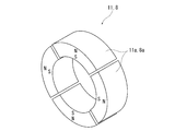
- a perspective view showing another example of a drive magnet and a return magnet The perspective view which shows the example which comprised the drive magnet and the return magnet from the segment magnet
- FIG. 1 is an external perspective view of a linear actuator.
- the linear actuator includes a cylindrical stator 1 and a cylindrical movable element 2 disposed inside the stator 1.
- the axis of the cylindrical stator 1 and the cylindrical movable element 2 coincide.
- the stator 1 is provided with a coil.
- the mover 2 is provided with a driving magnet. When a current is passed through the coil of the stator 1, the mover 2 moves in the axial direction.
- a flange 1a for attaching the stator 1 to an apparatus is provided at one end of the stator 1.
- a flange 2 a for attaching the mover 2 to the device is also provided at one end of the mover 2.
- Fig. 2 shows a cross-sectional view of the linear actuator.
- the first and second coils 4 a and 4 b are arranged as the coil 4 in the axial direction in a state in which the axes are aligned with each other.
- a cylindrical yoke 5 is provided outside the first and second coils 4a and 4b.
- the yoke 5 is made of a soft magnetic material such as iron, steel, silicon steel, and permalloy.
- a cylindrical resin case 6 is provided outside the yoke 5.
- One end portions of the yoke 5 and the case 6 in the axial direction are attached to the flange 1a. If the yoke 5 is rust-proofed, the resin case 6 is unnecessary.
- the coil 4 is supported by a bobbin or the like (not shown) and is integrated with the yoke 5 and the case 6.
- a hollow pipe 7 passing through the insides of the first and second coils 4a and 4b is fixed to the flange 1a.
- the pipe 7 is made of a nonmagnetic material such as resin.
- a cylindrical return magnet 8 is attached to the outer peripheral surface of the pipe 7. That is, the return magnet 8 is connected to the first and second coils 4a and 4b via the pipe 7, the flange 1a, and the yoke 5.
- the return magnet 8 is magnetized in the axial direction so that one end in the axial direction becomes the S pole and the other end becomes the N pole.
- the return magnet 8 is arranged at the center in the axial direction of the coil 4 composed of the first and second coils 4a and 4b.
- the length in the axial direction of the return magnet 8 is shorter than the length in the axial direction of the coil 4 composed of the first and second coils 4a and 4b.
- Cylindrical magnet support portions 9a and 9b made of a non-magnetic material such as resin are provided at both ends of the return magnet 8 in the axial direction.
- the configuration of the mover 2 is as follows.
- the mover 2 includes a cylindrical driving magnet 11.
- the drive magnet 11 is magnetized in the axial direction so that one end in the axial direction is an N pole and the other end is an S pole.
- the drive magnet 11 is disposed at the center of the return magnet 8 in the axial direction.
- the length L1 of the return magnet 8 in the axial direction is not less than the length L2 of the driving magnet 11 in the axial direction, preferably not less than 1 and not more than 1.2 times.
- the first and second yokes 12a and 12b made of a soft magnetic material such as iron, steel, silicon steel, and permalloy are provided at both ends of the drive magnet 11 in the axial direction. Both the first and second yokes 12a and 12b are formed in a cylindrical shape.
- a cylindrical slide bearing 14 made of a nonmagnetic material (for example, resin) is provided inside the drive magnet 11 and the first and second yokes 12a and 12b.
- the plain bearing 14 is made of a bush or a spline.
- the inner peripheral surface of the slide bearing 14 is in contact with the outer peripheral surfaces of the magnet support portions 9 a and 9 b of the stator 1.
- the linear movement of the mover 2 relative to the stator 1 in the axial direction is guided by the slide bearing 14.
- the sliding bearing 14 can be made of a magnetic material.
- the arrangement of the first and second coils 4a and 4b, the drive magnet 11, the first and second yokes 12a and 12b, and the return magnet 8 is as follows.
- the first and second coils 4 a and 4 b are arranged outside the hollow drive magnet 11.
- the first and second coils 4a and 4b and the drive magnet 11 are arranged concentrically, and the axis of the first and second coils 4a and 4b and the axis of the drive magnet 11 coincide.
- the return magnet 8 is disposed inside the hollow drive magnet 11.
- the return magnet 8 and the drive magnet 11 are arranged concentrically, and the axis of the return magnet 8 and the axis of the drive magnet 11 coincide.
- the first and second coils 4a and 4b face the first and second yokes 12a and 12b, respectively.
- the center-to-center pitch P1 of the first and second coils 4a, 4b (the length from the axial center of the first coil 4a to the axial center of the second coil 4b) and the first and second yokes
- the pitch P2 between the centers of 12a and 12b (the length from the center in the axial direction of the first yoke 12a to the center in the axial direction of the second coil 12b) is equal.
- the axial length of the first coil 4a is equal to the axial length of the second coil 4b
- the axial length of the first yoke 12a is equal to the axial length of the second yoke 12b.
- the length of the first and second yokes 12a and 12b in the axial direction is equal to or shorter than the length of the first and second coils 4a and 4b in the axial direction.
- the return magnet 8 causes the mover 2 to return to the origin shown in FIG.
- the center of the drive magnet 11 in the axial direction coincides with the center of the return magnet 8 in the axial direction.
- FIG. 3 shows first and second magnetic circuits formed by the drive magnet 11 and the return magnet 8.
- the magnetic flux generated at the north pole of the drive magnet 11 passes through the first yoke 12a, bends 90 °, passes through the first coil 4a, and passes through the yoke 5 outside the first coil 4a. Then, after passing through the yoke 5 in the axial direction, it bends by 90 °, passes through the second coil 4 b through the second yoke 12 b, and returns from the second yoke 12 b to the S pole of the driving magnet 11.
- the driving magnet 11 forms the first magnetic field circuit m1 that links the first and second coils 4a and 4b.
- the principle that the mover 2 returns to the origin is as follows.
- a part of the magnetic flux generated at the north pole of the drive magnet 11 changes its direction by 180 ° and enters the south pole of the return magnet 8.
- the magnetic flux generated at the north pole of the return magnet 8 changes direction by 180 ° and enters the south pole of the drive magnet 11.
- the drive magnet 11 and the return magnet 8 form a second magnetic circuit m2.
- the N pole of the drive magnet 11 and the S pole of the return magnet 8 attract each other, and the S pole of the drive magnet 11 and the N pole of the return magnet 8 attract each other, so that the mover 2 returns to the origin.
- FIG. 4 is a diagram showing the transition of the interlinkage magnetic flux of the first and second coils 4a and 4b when the mover 2 moves from the origin position to the right end of the stroke.
- the left column in FIG. 4 shows the position of the mover 2
- the right column in FIG. 4 shows the interlinkage magnetic flux of the first and second coils 4a and 4b.
- S1 shows a state where the mover 2 is located at the origin
- S2 ⁇ S4 shows a state where the mover 2 gradually moves rightward in FIG. 4
- S5 shows a state where the mover 2 is located at the right end of the stroke. Show.
- the right column in FIG. 4 is a graph showing the interlinkage magnetic flux of the first and second coils 4a and 4b.
- the first coil exists between 0 mm and 10 mm in the graph, and the second coil exists between 10 mm and 20 mm.
- the axial center of the first coil is 5 mm, and the axial center of the second coil is 15 mm.
- the radial component of the magnetic flux interlinking with the first and second coils 4a and 4b generates thrust in the first and second coils 4a and 4b. For this reason, the radial component of the flux linkage is shown in the graph of FIG.
- the first yoke 12a is located at the center of the first coil 4a
- the second yoke 12b is located at the center of the second coil 4b.
- the interlinkage magnetic flux of the first coil 4a and the interlinkage magnetic flux of the second coil 4b are both maximized.
- thrusts f1 and f2 in the same direction indicated by arrows in the graph of FIG. 4 are generated in the first and second coils 4a and 4b.
- the interlinkage magnetic flux of the first coil 4a is represented by plus the interlinkage magnetic flux facing outward in the radial direction
- the interlinkage magnetic flux of the second coil 4b is plus of the interlinkage magnetic flux pointing inward in the radial direction. It is represented.
- the linkage flux in the minus direction is indicated by R1
- the linkage flux in the plus direction is indicated by R2.
- the interlinkage magnetic flux includes a magnetic flux caused by the drive magnet 11 and a magnetic flux caused by the return magnet 8. Due to the interaction of these magnets, it is assumed that the closer the mover 2 is to the right end of the stroke, the more the linkage flux in the negative direction is generated.
- This minus direction linkage magnetic flux applies a braking force to the mover 2 that is about to move to the end of the stroke.
- the mover 2 By applying a braking force to the mover 2, the mover 2 can be prevented from jumping out of the stator 1 even when vibrated at high speed. Further, the closer the mover 2 is to the right end of the stroke, the smaller the total amount of interlinkage magnetic flux of the first and second coils 4a and 4b. This is also presumed to be a factor that can prevent the mover 2 from jumping out of the stator 1.
- the linear actuator according to this embodiment has the following effects. Since the coil 4 is arranged outside the hollow drive magnet 11 and the return magnet 8 is arranged inside the hollow drive magnet 11, the total length in the axial direction of the linear actuator can be shortened while the thrust is increased. it can. Further, since the hollow drive magnet 11 is disposed between the coil and the return magnet 8, it is easy to apply force to the drive magnet 11 from the coil 4 and the return magnet 8. This is also a factor that can increase the thrust of the linear actuator.
- the first and second coils 4a, 4b and the first The facing area between the first and second yokes 12a and 12b can be increased, and the magnetic flux generated by the drive magnet 11 can be efficiently linked to the first and second coils 4a and 4b.
- the drive magnet 11 is magnetized in the axial direction, and the first and second yokes 12 a and 12 b are disposed at both ends of the drive magnet 11 in the axial direction, so that the plain bearing 14 is provided inside the drive magnet 11. Can be arranged. Therefore, the radial dimension of the linear actuator can be suppressed.
- the length L1 of the return magnet 8 in the axial direction is set to 1 to 1.2 times the length L2 of the driving magnet 11 in the axial direction.
- the brake force can be applied.
- the sliding bearing 14 By arranging the sliding bearing 14 between the return magnet 8 and the drive magnet 11, it is possible to guide the drive magnet 11 to move in the axial direction with respect to the return magnet 8. Further, when the sliding bearing 14 is disposed between the driving magnet 11 and the coil 4, there is a possibility that the magnetic flux generated by the driving magnet 11 may be prevented from interlinking with the coil 4, but the return magnet 8 and the driving magnet By disposing the slide bearing 14 between the first and second bearings 11, the magnetic flux generated by the drive magnet 11 can be prevented from being adversely affected. Furthermore, by making the slide bearing 14 a nonmagnetic material, it is possible to further prevent adverse effects on the magnetic flux generated by the drive magnet 11.
- the radius of the coil 4 can be increased and the thrust of the linear actuator can be increased.
- the drive magnet 11 does not jump out of the return magnet 8.
- the restoring force for restoring the origin from the return magnet 8 to the drive magnet 11 can be reliably applied.
- the inside of the return magnet 8 can be effectively used as a space for wiring.
- a linear actuator is used as a vibration actuator, and the drive magnet is vibrated in the axial direction by energizing the coil.
- the position of the drive magnet in the axial direction is not caused to vibrate.
- the linear actuator can be used as a linear actuator that drives a shutter mechanism of the camera.
- the coil is arranged outside the hollow drive magnet and the return magnet is arranged inside the hollow drive magnet.
- the return magnet is arranged outside the hollow drive magnet.
- a coil can also be arranged inside the hollow drive magnet.
- the drive magnet and the return magnet are magnetized in the axial direction, but can be magnetized in the radial direction.
- half of the outer peripheral surfaces of the drive magnet 11 and the return magnet 8 in the axial direction are formed in the N pole, and the other half are formed in the S pole.
- the drive magnet 11 and the return magnet 8 may be configured by combining a plurality of segment magnets 11a and 8a divided in an arc shape.
- the driving magnet 11 is magnetized in the radial direction, it is necessary to dispose a yoke of a soft magnetic material inside the driving magnet 11, so that there is a problem that the radial dimension becomes large.
Landscapes
- Engineering & Computer Science (AREA)
- Power Engineering (AREA)
- Physics & Mathematics (AREA)
- Chemical & Material Sciences (AREA)
- Combustion & Propulsion (AREA)
- Electromagnetism (AREA)
- Reciprocating, Oscillating Or Vibrating Motors (AREA)
- Linear Motors (AREA)
Abstract
Description
Claims (6)
- 中空の駆動用磁石と、
前記駆動用磁石の外側及び内側のいずれか一方に配置されるコイルと、
前記駆動用磁石の外側及び内側の他方に配置されると共に前記コイルに連結され、前記駆動用磁石を原点に復帰させる復帰用磁石と、を備え、
前記コイルに通電することによって、前記駆動用磁石又は前記コイル及び前記復帰用磁石が前記駆動用磁石の軸線方向に移動するリニアアクチュエータ。 - 前記駆動用磁石は、前記駆動用磁石の前記軸線方向の一端部がN極に他端部がS極になるように前記軸線方向に磁化されており、
前記駆動用磁石の軸線方向の両端部には、軟質磁性材料の第一及び第二のヨークが設けられ、
前記コイルは、前記第一のヨークに対向する第一のコイル、及び前記第二のヨークに対向する第二のコイルを有することを特徴とする請求項1に記載のリニアアクチュエータ。 - 前記復帰用磁石の前記軸線方向の長さは、前記駆動用磁石の前記軸線方向の長さ以上であることを特徴とする請求項1又は2に記載のリニアアクチュエータ。
- 前記復帰用磁石と前記駆動用磁石との間には、前記駆動用磁石が前記復帰用磁石に対して相対的に前記軸線方向に移動するのを案内するすべり軸受が配置されることを特徴とする請求項2に記載のリニアアクチュエータ。
- 前記駆動用磁石の外側に前記コイルが配置され、前記駆動用磁石の内側に前記復帰用磁石が配置されることを特徴とする請求項1又は2に記載のリニアアクチュエータ。
- 前記復帰用磁石は中空に形成されることを特徴とする請求項5に記載のリニアアクチュエータ。
Priority Applications (3)
| Application Number | Priority Date | Filing Date | Title |
|---|---|---|---|
| US14/896,083 US9906113B2 (en) | 2013-06-05 | 2014-05-02 | Linear actuator |
| CN201480031855.9A CN105264756B (zh) | 2013-06-05 | 2014-05-02 | 线性致动器 |
| DE112014002719.7T DE112014002719B4 (de) | 2013-06-05 | 2014-05-02 | Linearaktuator |
Applications Claiming Priority (2)
| Application Number | Priority Date | Filing Date | Title |
|---|---|---|---|
| JP2013-118492 | 2013-06-05 | ||
| JP2013118492A JP5766748B2 (ja) | 2013-06-05 | 2013-06-05 | リニアアクチュエータ |
Publications (1)
| Publication Number | Publication Date |
|---|---|
| WO2014196298A1 true WO2014196298A1 (ja) | 2014-12-11 |
Family
ID=52007951
Family Applications (1)
| Application Number | Title | Priority Date | Filing Date |
|---|---|---|---|
| PCT/JP2014/062150 Ceased WO2014196298A1 (ja) | 2013-06-05 | 2014-05-02 | リニアアクチュエータ |
Country Status (6)
| Country | Link |
|---|---|
| US (1) | US9906113B2 (ja) |
| JP (1) | JP5766748B2 (ja) |
| CN (1) | CN105264756B (ja) |
| DE (1) | DE112014002719B4 (ja) |
| TW (1) | TWI600256B (ja) |
| WO (1) | WO2014196298A1 (ja) |
Families Citing this family (32)
| Publication number | Priority date | Publication date | Assignee | Title |
|---|---|---|---|---|
| JP5766748B2 (ja) * | 2013-06-05 | 2015-08-19 | Thk株式会社 | リニアアクチュエータ |
| JP6715101B2 (ja) * | 2016-06-20 | 2020-07-01 | 株式会社東芝 | 振動発電機、振動発電ユニット、振動発電モジュールおよび電気機器 |
| KR102034761B1 (ko) * | 2016-07-15 | 2019-10-22 | 주식회사 엠플러스 | 선형 진동 발생장치. |
| US10404149B2 (en) | 2016-11-03 | 2019-09-03 | Immersion Corporation | Electromagnetic haptic actuator with high definition capability |
| DE102017103090B4 (de) * | 2017-02-15 | 2020-06-04 | Kolektor Group D.O.O. | Elektromagnetischer Linearaktuator |
| WO2019097307A1 (en) * | 2017-11-15 | 2019-05-23 | Rakesh Goel | Electro-dynamic vibration generating apparatus |
| CN108081246B (zh) * | 2017-12-29 | 2021-01-15 | 南通市一家人大药房有限公司 | 一种人工肌肉装置及其驱动方法 |
| CN107979259A (zh) * | 2018-01-12 | 2018-05-01 | 河南省皓泽电子有限公司 | 一种记忆合金驱动的微型电机 |
| JP7034745B2 (ja) * | 2018-01-31 | 2022-03-14 | 日本電産サンキョー株式会社 | アクチュエータ |
| KR101889458B1 (ko) | 2018-02-21 | 2018-09-20 | (주)신호엔지니어링 | 수배전반용 마그넷 면진장치 |
| GB2572350B (en) * | 2018-03-27 | 2023-01-25 | Hitachi Rail Ltd | An electromechanical generator for converting mechanical vibrational energy into electrical energy |
| GB2572349B (en) * | 2018-03-27 | 2021-08-11 | Perpetuum Ltd | An electromechanical generator for converting mechanical vibrational energy into electrical energy |
| JP7063691B2 (ja) * | 2018-04-06 | 2022-05-09 | フォスター電機株式会社 | 振動アクチュエータ |
| JP6750825B2 (ja) * | 2018-08-28 | 2020-09-02 | ミネベアミツミ株式会社 | 振動アクチュエータ及び電子機器 |
| KR102177140B1 (ko) * | 2019-01-18 | 2020-11-10 | 효성중공업 주식회사 | 액츄에이터 |
| US11499536B2 (en) * | 2019-01-25 | 2022-11-15 | Rensselaer Polytechnic Institute | Cylindrical magnetic coupling with alternating polarity |
| EP3954133B1 (de) | 2019-04-11 | 2024-02-21 | Continental Engineering Services GmbH | Schwingungsaktuator für steife strukturen zur hochleistungs-basswiedergabe im automobilbereich |
| US20210013786A1 (en) * | 2019-07-08 | 2021-01-14 | West Virginia University | High frequency resonant linear machines |
| US20210067023A1 (en) * | 2019-08-30 | 2021-03-04 | Apple Inc. | Haptic actuator including shaft coupled field member and related methods |
| KR20210047576A (ko) * | 2019-10-22 | 2021-04-30 | 주식회사 씨케이머티리얼즈랩 | 래디얼 마그넷 액추에이터 |
| KR102230962B1 (ko) * | 2020-01-09 | 2021-03-23 | 한밭대학교 산학협력단 | 액츄에이터 |
| JP7410791B2 (ja) * | 2020-04-28 | 2024-01-10 | ニデックインスツルメンツ株式会社 | アクチュエータ |
| CN113572333B (zh) * | 2020-04-28 | 2024-03-29 | 日本电产三协株式会社 | 致动器 |
| JP2022049071A (ja) * | 2020-09-16 | 2022-03-29 | 株式会社東芝 | 振動発電機 |
| DE102020213768A1 (de) * | 2020-11-02 | 2022-05-05 | Continental Engineering Services Gmbh | Aktuator zur Anregung von Schwingungen umfassend einen Antrieb mit verbesserter Dämpfung |
| JP7827258B2 (ja) * | 2021-06-30 | 2026-03-10 | ミネベアミツミ株式会社 | 振動アクチュエータ及び電気機器 |
| FR3130091B1 (fr) * | 2021-12-02 | 2025-02-14 | Commissariat Energie Atomique | Transducteur électromagnétique pour la récupération d’énergie vibratoire |
| US12205761B2 (en) | 2022-01-25 | 2025-01-21 | Robert Bosch Gmbh | Methods, materials and structures for manufacturing a magnetically actuated exciter device using 3D printing |
| US11781941B2 (en) | 2022-01-25 | 2023-10-10 | Robert Bosch Gmbh | Multi-degree-of-freedom impedance fixture for automated frequency response function measurements |
| US12255512B2 (en) | 2022-01-25 | 2025-03-18 | Robert Bosch Gmbh | Axial and radial suspension for a magnetically actuated exciter device |
| US12104987B2 (en) | 2022-01-25 | 2024-10-01 | Robert Bosch Gmbh | Analyzing quality of sensed force-response data during testing and mitigation poor quality output |
| US12105060B2 (en) | 2022-01-25 | 2024-10-01 | Robert Bosch Gmbh | Magnetically actuated exciter device with impact function |
Citations (5)
| Publication number | Priority date | Publication date | Assignee | Title |
|---|---|---|---|---|
| JPS61106058A (ja) * | 1984-10-30 | 1986-05-24 | Yaskawa Electric Mfg Co Ltd | 微少変位リニア電磁アクチユエ−タ |
| JPH0739268U (ja) * | 1993-12-27 | 1995-07-14 | フオスター電機株式会社 | 振動アクチュエータ |
| JPH11197601A (ja) * | 1998-01-09 | 1999-07-27 | Star Micronics Co Ltd | 携帯電子機器 |
| JPH11313476A (ja) * | 1998-04-28 | 1999-11-09 | Matsushita Refrig Co Ltd | リニアモータ |
| JP2010268672A (ja) * | 2009-04-15 | 2010-11-25 | Thk Co Ltd | リニアモータアクチュエータ |
Family Cites Families (15)
| Publication number | Priority date | Publication date | Assignee | Title |
|---|---|---|---|---|
| CN1074788A (zh) * | 1992-01-25 | 1993-07-28 | 辉光系统有限公司 | 电磁致动器 |
| EP0580117A3 (en) * | 1992-07-20 | 1994-08-24 | Tdk Corp | Moving magnet-type actuator |
| AU8877398A (en) * | 1997-10-04 | 1999-04-27 | Wei-Min Zhang | Linear motor compressor |
| KR100295178B1 (ko) | 1998-04-28 | 2001-09-07 | 구보다 다다시 | 선형모터 및 선형압축기 |
| US6501357B2 (en) * | 2000-03-16 | 2002-12-31 | Quizix, Inc. | Permanent magnet actuator mechanism |
| US7768160B1 (en) * | 2005-03-21 | 2010-08-03 | Sahyoun Joseph Y | Electromagnetic motor to create a desired low frequency vibration or to cancel an undesired low frequency vibration |
| EP1705785B1 (en) * | 2005-03-21 | 2008-06-25 | Sony Ericsson Mobile Communications AB | Vibrator tube |
| US7449803B2 (en) * | 2005-03-21 | 2008-11-11 | Sahyoun Joseph Y | Electromagnetic motor to create a desired low frequency vibration or to cancel an undesired low frequency vibration |
| US7859144B1 (en) * | 2006-08-31 | 2010-12-28 | Joseph Y Sahyoun | Low frequency electromagnetic motor to create or cancel a low frequency vibration |
| CN102362093B (zh) * | 2009-04-08 | 2014-01-15 | 东海橡塑工业株式会社 | 能动型减振器及能动型减振器的制造方法 |
| EP2456982A4 (en) * | 2009-07-22 | 2017-06-14 | Vbox Incorporated | Gaseous fluid pump |
| DE102010000582A1 (de) * | 2010-02-26 | 2011-09-01 | Karl Storz Gmbh & Co. Kg | Linearmotor mit permanentmagnetischer Selbsthaltung |
| US20130169071A1 (en) | 2010-06-30 | 2013-07-04 | Nidec Copal Corporation | Oscillating actuator |
| JP5929241B2 (ja) * | 2012-01-30 | 2016-06-01 | ミツミ電機株式会社 | アクチュエーター及び電動理美容器具 |
| JP5766748B2 (ja) * | 2013-06-05 | 2015-08-19 | Thk株式会社 | リニアアクチュエータ |
-
2013
- 2013-06-05 JP JP2013118492A patent/JP5766748B2/ja active Active
-
2014
- 2014-05-02 WO PCT/JP2014/062150 patent/WO2014196298A1/ja not_active Ceased
- 2014-05-02 US US14/896,083 patent/US9906113B2/en active Active
- 2014-05-02 DE DE112014002719.7T patent/DE112014002719B4/de active Active
- 2014-05-02 CN CN201480031855.9A patent/CN105264756B/zh active Active
- 2014-05-22 TW TW103117896A patent/TWI600256B/zh active
Patent Citations (5)
| Publication number | Priority date | Publication date | Assignee | Title |
|---|---|---|---|---|
| JPS61106058A (ja) * | 1984-10-30 | 1986-05-24 | Yaskawa Electric Mfg Co Ltd | 微少変位リニア電磁アクチユエ−タ |
| JPH0739268U (ja) * | 1993-12-27 | 1995-07-14 | フオスター電機株式会社 | 振動アクチュエータ |
| JPH11197601A (ja) * | 1998-01-09 | 1999-07-27 | Star Micronics Co Ltd | 携帯電子機器 |
| JPH11313476A (ja) * | 1998-04-28 | 1999-11-09 | Matsushita Refrig Co Ltd | リニアモータ |
| JP2010268672A (ja) * | 2009-04-15 | 2010-11-25 | Thk Co Ltd | リニアモータアクチュエータ |
Also Published As
| Publication number | Publication date |
|---|---|
| DE112014002719T5 (de) | 2016-03-17 |
| DE112014002719B4 (de) | 2021-05-06 |
| US20160126821A1 (en) | 2016-05-05 |
| US9906113B2 (en) | 2018-02-27 |
| CN105264756B (zh) | 2018-04-03 |
| TWI600256B (zh) | 2017-09-21 |
| JP2014236642A (ja) | 2014-12-15 |
| JP5766748B2 (ja) | 2015-08-19 |
| TW201507327A (zh) | 2015-02-16 |
| CN105264756A (zh) | 2016-01-20 |
Similar Documents
| Publication | Publication Date | Title |
|---|---|---|
| JP5766748B2 (ja) | リニアアクチュエータ | |
| JP5604097B2 (ja) | リニアモータアクチュエータ | |
| US10399122B2 (en) | Vibration motor | |
| JP7591770B2 (ja) | レンズ鏡筒、撮像装置 | |
| JP2010041761A (ja) | リニアモータ | |
| JP5116317B2 (ja) | 円筒型リニアモータ | |
| JP2007282475A (ja) | リニアモータとアクチュエータ | |
| JP5792847B2 (ja) | リニアモータアクチュエータ | |
| JP5662095B2 (ja) | リニアモータアクチュエータ | |
| KR930007591B1 (ko) | 스텝선형 구동장치 | |
| JPWO2011055427A1 (ja) | 駆動装置 | |
| WO2008143492A1 (en) | Linear motion device | |
| JP6587472B2 (ja) | アクチュエータ | |
| JP6110165B2 (ja) | リニアモータ | |
| JP2013021779A (ja) | 慣性駆動アクチュエータ | |
| JP5452090B2 (ja) | リニアアクチュエータ | |
| JP2009194991A (ja) | リニアモータとアクチュエータ | |
| JP5696403B2 (ja) | リニアアクチュエータ | |
| JP3669393B2 (ja) | ディスク装置用リニアアクチュエータ | |
| CN103460575B (zh) | 直线电动机 | |
| JP2008178219A (ja) | 駆動装置およびレンズ駆動装置 | |
| JP2016019315A (ja) | リニアモータ、及びそれを用いた駆動システム | |
| JP2024006584A (ja) | リニアモータ | |
| JP2020188576A (ja) | ボイスコイルモータおよびステージ装置 | |
| JP2013219998A (ja) | モータ装置及びステージ装置 |
Legal Events
| Date | Code | Title | Description |
|---|---|---|---|
| WWE | Wipo information: entry into national phase |
Ref document number: 201480031855.9 Country of ref document: CN |
|
| 121 | Ep: the epo has been informed by wipo that ep was designated in this application |
Ref document number: 14807703 Country of ref document: EP Kind code of ref document: A1 |
|
| WWE | Wipo information: entry into national phase |
Ref document number: 14896083 Country of ref document: US |
|
| WWE | Wipo information: entry into national phase |
Ref document number: 112014002719 Country of ref document: DE |
|
| 122 | Ep: pct application non-entry in european phase |
Ref document number: 14807703 Country of ref document: EP Kind code of ref document: A1 |