WO2014196244A1 - ハイブリッド車両の制御装置 - Google Patents
ハイブリッド車両の制御装置 Download PDFInfo
- Publication number
- WO2014196244A1 WO2014196244A1 PCT/JP2014/058510 JP2014058510W WO2014196244A1 WO 2014196244 A1 WO2014196244 A1 WO 2014196244A1 JP 2014058510 W JP2014058510 W JP 2014058510W WO 2014196244 A1 WO2014196244 A1 WO 2014196244A1
- Authority
- WO
- WIPO (PCT)
- Prior art keywords
- capacitor
- voltage
- starter
- motor
- engine
- Prior art date
Links
Images


Classifications
-
- B—PERFORMING OPERATIONS; TRANSPORTING
- B60—VEHICLES IN GENERAL
- B60W—CONJOINT CONTROL OF VEHICLE SUB-UNITS OF DIFFERENT TYPE OR DIFFERENT FUNCTION; CONTROL SYSTEMS SPECIALLY ADAPTED FOR HYBRID VEHICLES; ROAD VEHICLE DRIVE CONTROL SYSTEMS FOR PURPOSES NOT RELATED TO THE CONTROL OF A PARTICULAR SUB-UNIT
- B60W20/00—Control systems specially adapted for hybrid vehicles
- B60W20/40—Controlling the engagement or disengagement of prime movers, e.g. for transition between prime movers
-
- B—PERFORMING OPERATIONS; TRANSPORTING
- B60—VEHICLES IN GENERAL
- B60K—ARRANGEMENT OR MOUNTING OF PROPULSION UNITS OR OF TRANSMISSIONS IN VEHICLES; ARRANGEMENT OR MOUNTING OF PLURAL DIVERSE PRIME-MOVERS IN VEHICLES; AUXILIARY DRIVES FOR VEHICLES; INSTRUMENTATION OR DASHBOARDS FOR VEHICLES; ARRANGEMENTS IN CONNECTION WITH COOLING, AIR INTAKE, GAS EXHAUST OR FUEL SUPPLY OF PROPULSION UNITS IN VEHICLES
- B60K6/00—Arrangement or mounting of plural diverse prime-movers for mutual or common propulsion, e.g. hybrid propulsion systems comprising electric motors and internal combustion engines ; Control systems therefor, i.e. systems controlling two or more prime movers, or controlling one of these prime movers and any of the transmission, drive or drive units Informative references: mechanical gearings with secondary electric drive F16H3/72; arrangements for handling mechanical energy structurally associated with the dynamo-electric machine H02K7/00; machines comprising structurally interrelated motor and generator parts H02K51/00; dynamo-electric machines not otherwise provided for in H02K see H02K99/00
- B60K6/20—Arrangement or mounting of plural diverse prime-movers for mutual or common propulsion, e.g. hybrid propulsion systems comprising electric motors and internal combustion engines ; Control systems therefor, i.e. systems controlling two or more prime movers, or controlling one of these prime movers and any of the transmission, drive or drive units Informative references: mechanical gearings with secondary electric drive F16H3/72; arrangements for handling mechanical energy structurally associated with the dynamo-electric machine H02K7/00; machines comprising structurally interrelated motor and generator parts H02K51/00; dynamo-electric machines not otherwise provided for in H02K see H02K99/00 the prime-movers consisting of electric motors and internal combustion engines, e.g. HEVs
- B60K6/22—Arrangement or mounting of plural diverse prime-movers for mutual or common propulsion, e.g. hybrid propulsion systems comprising electric motors and internal combustion engines ; Control systems therefor, i.e. systems controlling two or more prime movers, or controlling one of these prime movers and any of the transmission, drive or drive units Informative references: mechanical gearings with secondary electric drive F16H3/72; arrangements for handling mechanical energy structurally associated with the dynamo-electric machine H02K7/00; machines comprising structurally interrelated motor and generator parts H02K51/00; dynamo-electric machines not otherwise provided for in H02K see H02K99/00 the prime-movers consisting of electric motors and internal combustion engines, e.g. HEVs characterised by apparatus, components or means specially adapted for HEVs
- B60K6/28—Arrangement or mounting of plural diverse prime-movers for mutual or common propulsion, e.g. hybrid propulsion systems comprising electric motors and internal combustion engines ; Control systems therefor, i.e. systems controlling two or more prime movers, or controlling one of these prime movers and any of the transmission, drive or drive units Informative references: mechanical gearings with secondary electric drive F16H3/72; arrangements for handling mechanical energy structurally associated with the dynamo-electric machine H02K7/00; machines comprising structurally interrelated motor and generator parts H02K51/00; dynamo-electric machines not otherwise provided for in H02K see H02K99/00 the prime-movers consisting of electric motors and internal combustion engines, e.g. HEVs characterised by apparatus, components or means specially adapted for HEVs characterised by the electric energy storing means, e.g. batteries or capacitors
-
- B—PERFORMING OPERATIONS; TRANSPORTING
- B60—VEHICLES IN GENERAL
- B60K—ARRANGEMENT OR MOUNTING OF PROPULSION UNITS OR OF TRANSMISSIONS IN VEHICLES; ARRANGEMENT OR MOUNTING OF PLURAL DIVERSE PRIME-MOVERS IN VEHICLES; AUXILIARY DRIVES FOR VEHICLES; INSTRUMENTATION OR DASHBOARDS FOR VEHICLES; ARRANGEMENTS IN CONNECTION WITH COOLING, AIR INTAKE, GAS EXHAUST OR FUEL SUPPLY OF PROPULSION UNITS IN VEHICLES
- B60K6/00—Arrangement or mounting of plural diverse prime-movers for mutual or common propulsion, e.g. hybrid propulsion systems comprising electric motors and internal combustion engines ; Control systems therefor, i.e. systems controlling two or more prime movers, or controlling one of these prime movers and any of the transmission, drive or drive units Informative references: mechanical gearings with secondary electric drive F16H3/72; arrangements for handling mechanical energy structurally associated with the dynamo-electric machine H02K7/00; machines comprising structurally interrelated motor and generator parts H02K51/00; dynamo-electric machines not otherwise provided for in H02K see H02K99/00
- B60K6/20—Arrangement or mounting of plural diverse prime-movers for mutual or common propulsion, e.g. hybrid propulsion systems comprising electric motors and internal combustion engines ; Control systems therefor, i.e. systems controlling two or more prime movers, or controlling one of these prime movers and any of the transmission, drive or drive units Informative references: mechanical gearings with secondary electric drive F16H3/72; arrangements for handling mechanical energy structurally associated with the dynamo-electric machine H02K7/00; machines comprising structurally interrelated motor and generator parts H02K51/00; dynamo-electric machines not otherwise provided for in H02K see H02K99/00 the prime-movers consisting of electric motors and internal combustion engines, e.g. HEVs
- B60K6/42—Arrangement or mounting of plural diverse prime-movers for mutual or common propulsion, e.g. hybrid propulsion systems comprising electric motors and internal combustion engines ; Control systems therefor, i.e. systems controlling two or more prime movers, or controlling one of these prime movers and any of the transmission, drive or drive units Informative references: mechanical gearings with secondary electric drive F16H3/72; arrangements for handling mechanical energy structurally associated with the dynamo-electric machine H02K7/00; machines comprising structurally interrelated motor and generator parts H02K51/00; dynamo-electric machines not otherwise provided for in H02K see H02K99/00 the prime-movers consisting of electric motors and internal combustion engines, e.g. HEVs characterised by the architecture of the hybrid electric vehicle
- B60K6/48—Parallel type
-
- B—PERFORMING OPERATIONS; TRANSPORTING
- B60—VEHICLES IN GENERAL
- B60K—ARRANGEMENT OR MOUNTING OF PROPULSION UNITS OR OF TRANSMISSIONS IN VEHICLES; ARRANGEMENT OR MOUNTING OF PLURAL DIVERSE PRIME-MOVERS IN VEHICLES; AUXILIARY DRIVES FOR VEHICLES; INSTRUMENTATION OR DASHBOARDS FOR VEHICLES; ARRANGEMENTS IN CONNECTION WITH COOLING, AIR INTAKE, GAS EXHAUST OR FUEL SUPPLY OF PROPULSION UNITS IN VEHICLES
- B60K6/00—Arrangement or mounting of plural diverse prime-movers for mutual or common propulsion, e.g. hybrid propulsion systems comprising electric motors and internal combustion engines ; Control systems therefor, i.e. systems controlling two or more prime movers, or controlling one of these prime movers and any of the transmission, drive or drive units Informative references: mechanical gearings with secondary electric drive F16H3/72; arrangements for handling mechanical energy structurally associated with the dynamo-electric machine H02K7/00; machines comprising structurally interrelated motor and generator parts H02K51/00; dynamo-electric machines not otherwise provided for in H02K see H02K99/00
- B60K6/20—Arrangement or mounting of plural diverse prime-movers for mutual or common propulsion, e.g. hybrid propulsion systems comprising electric motors and internal combustion engines ; Control systems therefor, i.e. systems controlling two or more prime movers, or controlling one of these prime movers and any of the transmission, drive or drive units Informative references: mechanical gearings with secondary electric drive F16H3/72; arrangements for handling mechanical energy structurally associated with the dynamo-electric machine H02K7/00; machines comprising structurally interrelated motor and generator parts H02K51/00; dynamo-electric machines not otherwise provided for in H02K see H02K99/00 the prime-movers consisting of electric motors and internal combustion engines, e.g. HEVs
- B60K6/50—Architecture of the driveline characterised by arrangement or kind of transmission units
- B60K6/54—Transmission for changing ratio
- B60K6/543—Transmission for changing ratio the transmission being a continuously variable transmission
-
- B—PERFORMING OPERATIONS; TRANSPORTING
- B60—VEHICLES IN GENERAL
- B60L—PROPULSION OF ELECTRICALLY-PROPELLED VEHICLES; SUPPLYING ELECTRIC POWER FOR AUXILIARY EQUIPMENT OF ELECTRICALLY-PROPELLED VEHICLES; ELECTRODYNAMIC BRAKE SYSTEMS FOR VEHICLES IN GENERAL; MAGNETIC SUSPENSION OR LEVITATION FOR VEHICLES; MONITORING OPERATING VARIABLES OF ELECTRICALLY-PROPELLED VEHICLES; ELECTRIC SAFETY DEVICES FOR ELECTRICALLY-PROPELLED VEHICLES
- B60L1/00—Supplying electric power to auxiliary equipment of vehicles
- B60L1/003—Supplying electric power to auxiliary equipment of vehicles to auxiliary motors, e.g. for pumps, compressors
-
- B—PERFORMING OPERATIONS; TRANSPORTING
- B60—VEHICLES IN GENERAL
- B60L—PROPULSION OF ELECTRICALLY-PROPELLED VEHICLES; SUPPLYING ELECTRIC POWER FOR AUXILIARY EQUIPMENT OF ELECTRICALLY-PROPELLED VEHICLES; ELECTRODYNAMIC BRAKE SYSTEMS FOR VEHICLES IN GENERAL; MAGNETIC SUSPENSION OR LEVITATION FOR VEHICLES; MONITORING OPERATING VARIABLES OF ELECTRICALLY-PROPELLED VEHICLES; ELECTRIC SAFETY DEVICES FOR ELECTRICALLY-PROPELLED VEHICLES
- B60L15/00—Methods, circuits, or devices for controlling the traction-motor speed of electrically-propelled vehicles
- B60L15/20—Methods, circuits, or devices for controlling the traction-motor speed of electrically-propelled vehicles for control of the vehicle or its driving motor to achieve a desired performance, e.g. speed, torque, programmed variation of speed
- B60L15/2009—Methods, circuits, or devices for controlling the traction-motor speed of electrically-propelled vehicles for control of the vehicle or its driving motor to achieve a desired performance, e.g. speed, torque, programmed variation of speed for braking
-
- B—PERFORMING OPERATIONS; TRANSPORTING
- B60—VEHICLES IN GENERAL
- B60L—PROPULSION OF ELECTRICALLY-PROPELLED VEHICLES; SUPPLYING ELECTRIC POWER FOR AUXILIARY EQUIPMENT OF ELECTRICALLY-PROPELLED VEHICLES; ELECTRODYNAMIC BRAKE SYSTEMS FOR VEHICLES IN GENERAL; MAGNETIC SUSPENSION OR LEVITATION FOR VEHICLES; MONITORING OPERATING VARIABLES OF ELECTRICALLY-PROPELLED VEHICLES; ELECTRIC SAFETY DEVICES FOR ELECTRICALLY-PROPELLED VEHICLES
- B60L3/00—Electric devices on electrically-propelled vehicles for safety purposes; Monitoring operating variables, e.g. speed, deceleration or energy consumption
- B60L3/0023—Detecting, eliminating, remedying or compensating for drive train abnormalities, e.g. failures within the drive train
-
- B—PERFORMING OPERATIONS; TRANSPORTING
- B60—VEHICLES IN GENERAL
- B60L—PROPULSION OF ELECTRICALLY-PROPELLED VEHICLES; SUPPLYING ELECTRIC POWER FOR AUXILIARY EQUIPMENT OF ELECTRICALLY-PROPELLED VEHICLES; ELECTRODYNAMIC BRAKE SYSTEMS FOR VEHICLES IN GENERAL; MAGNETIC SUSPENSION OR LEVITATION FOR VEHICLES; MONITORING OPERATING VARIABLES OF ELECTRICALLY-PROPELLED VEHICLES; ELECTRIC SAFETY DEVICES FOR ELECTRICALLY-PROPELLED VEHICLES
- B60L50/00—Electric propulsion with power supplied within the vehicle
- B60L50/10—Electric propulsion with power supplied within the vehicle using propulsion power supplied by engine-driven generators, e.g. generators driven by combustion engines
- B60L50/16—Electric propulsion with power supplied within the vehicle using propulsion power supplied by engine-driven generators, e.g. generators driven by combustion engines with provision for separate direct mechanical propulsion
-
- B—PERFORMING OPERATIONS; TRANSPORTING
- B60—VEHICLES IN GENERAL
- B60L—PROPULSION OF ELECTRICALLY-PROPELLED VEHICLES; SUPPLYING ELECTRIC POWER FOR AUXILIARY EQUIPMENT OF ELECTRICALLY-PROPELLED VEHICLES; ELECTRODYNAMIC BRAKE SYSTEMS FOR VEHICLES IN GENERAL; MAGNETIC SUSPENSION OR LEVITATION FOR VEHICLES; MONITORING OPERATING VARIABLES OF ELECTRICALLY-PROPELLED VEHICLES; ELECTRIC SAFETY DEVICES FOR ELECTRICALLY-PROPELLED VEHICLES
- B60L50/00—Electric propulsion with power supplied within the vehicle
- B60L50/40—Electric propulsion with power supplied within the vehicle using propulsion power supplied by capacitors
-
- B—PERFORMING OPERATIONS; TRANSPORTING
- B60—VEHICLES IN GENERAL
- B60L—PROPULSION OF ELECTRICALLY-PROPELLED VEHICLES; SUPPLYING ELECTRIC POWER FOR AUXILIARY EQUIPMENT OF ELECTRICALLY-PROPELLED VEHICLES; ELECTRODYNAMIC BRAKE SYSTEMS FOR VEHICLES IN GENERAL; MAGNETIC SUSPENSION OR LEVITATION FOR VEHICLES; MONITORING OPERATING VARIABLES OF ELECTRICALLY-PROPELLED VEHICLES; ELECTRIC SAFETY DEVICES FOR ELECTRICALLY-PROPELLED VEHICLES
- B60L53/00—Methods of charging batteries, specially adapted for electric vehicles; Charging stations or on-board charging equipment therefor; Exchange of energy storage elements in electric vehicles
- B60L53/10—Methods of charging batteries, specially adapted for electric vehicles; Charging stations or on-board charging equipment therefor; Exchange of energy storage elements in electric vehicles characterised by the energy transfer between the charging station and the vehicle
- B60L53/14—Conductive energy transfer
-
- B—PERFORMING OPERATIONS; TRANSPORTING
- B60—VEHICLES IN GENERAL
- B60L—PROPULSION OF ELECTRICALLY-PROPELLED VEHICLES; SUPPLYING ELECTRIC POWER FOR AUXILIARY EQUIPMENT OF ELECTRICALLY-PROPELLED VEHICLES; ELECTRODYNAMIC BRAKE SYSTEMS FOR VEHICLES IN GENERAL; MAGNETIC SUSPENSION OR LEVITATION FOR VEHICLES; MONITORING OPERATING VARIABLES OF ELECTRICALLY-PROPELLED VEHICLES; ELECTRIC SAFETY DEVICES FOR ELECTRICALLY-PROPELLED VEHICLES
- B60L58/00—Methods or circuit arrangements for monitoring or controlling batteries or fuel cells, specially adapted for electric vehicles
- B60L58/10—Methods or circuit arrangements for monitoring or controlling batteries or fuel cells, specially adapted for electric vehicles for monitoring or controlling batteries
- B60L58/18—Methods or circuit arrangements for monitoring or controlling batteries or fuel cells, specially adapted for electric vehicles for monitoring or controlling batteries of two or more battery modules
- B60L58/20—Methods or circuit arrangements for monitoring or controlling batteries or fuel cells, specially adapted for electric vehicles for monitoring or controlling batteries of two or more battery modules having different nominal voltages
-
- B—PERFORMING OPERATIONS; TRANSPORTING
- B60—VEHICLES IN GENERAL
- B60L—PROPULSION OF ELECTRICALLY-PROPELLED VEHICLES; SUPPLYING ELECTRIC POWER FOR AUXILIARY EQUIPMENT OF ELECTRICALLY-PROPELLED VEHICLES; ELECTRODYNAMIC BRAKE SYSTEMS FOR VEHICLES IN GENERAL; MAGNETIC SUSPENSION OR LEVITATION FOR VEHICLES; MONITORING OPERATING VARIABLES OF ELECTRICALLY-PROPELLED VEHICLES; ELECTRIC SAFETY DEVICES FOR ELECTRICALLY-PROPELLED VEHICLES
- B60L7/00—Electrodynamic brake systems for vehicles in general
- B60L7/10—Dynamic electric regenerative braking
- B60L7/14—Dynamic electric regenerative braking for vehicles propelled by ac motors
-
- B—PERFORMING OPERATIONS; TRANSPORTING
- B60—VEHICLES IN GENERAL
- B60W—CONJOINT CONTROL OF VEHICLE SUB-UNITS OF DIFFERENT TYPE OR DIFFERENT FUNCTION; CONTROL SYSTEMS SPECIALLY ADAPTED FOR HYBRID VEHICLES; ROAD VEHICLE DRIVE CONTROL SYSTEMS FOR PURPOSES NOT RELATED TO THE CONTROL OF A PARTICULAR SUB-UNIT
- B60W10/00—Conjoint control of vehicle sub-units of different type or different function
- B60W10/04—Conjoint control of vehicle sub-units of different type or different function including control of propulsion units
- B60W10/06—Conjoint control of vehicle sub-units of different type or different function including control of propulsion units including control of combustion engines
-
- B—PERFORMING OPERATIONS; TRANSPORTING
- B60—VEHICLES IN GENERAL
- B60W—CONJOINT CONTROL OF VEHICLE SUB-UNITS OF DIFFERENT TYPE OR DIFFERENT FUNCTION; CONTROL SYSTEMS SPECIALLY ADAPTED FOR HYBRID VEHICLES; ROAD VEHICLE DRIVE CONTROL SYSTEMS FOR PURPOSES NOT RELATED TO THE CONTROL OF A PARTICULAR SUB-UNIT
- B60W10/00—Conjoint control of vehicle sub-units of different type or different function
- B60W10/04—Conjoint control of vehicle sub-units of different type or different function including control of propulsion units
- B60W10/08—Conjoint control of vehicle sub-units of different type or different function including control of propulsion units including control of electric propulsion units, e.g. motors or generators
-
- B—PERFORMING OPERATIONS; TRANSPORTING
- B60—VEHICLES IN GENERAL
- B60W—CONJOINT CONTROL OF VEHICLE SUB-UNITS OF DIFFERENT TYPE OR DIFFERENT FUNCTION; CONTROL SYSTEMS SPECIALLY ADAPTED FOR HYBRID VEHICLES; ROAD VEHICLE DRIVE CONTROL SYSTEMS FOR PURPOSES NOT RELATED TO THE CONTROL OF A PARTICULAR SUB-UNIT
- B60W10/00—Conjoint control of vehicle sub-units of different type or different function
- B60W10/24—Conjoint control of vehicle sub-units of different type or different function including control of energy storage means
- B60W10/26—Conjoint control of vehicle sub-units of different type or different function including control of energy storage means for electrical energy, e.g. batteries or capacitors
-
- B—PERFORMING OPERATIONS; TRANSPORTING
- B60—VEHICLES IN GENERAL
- B60L—PROPULSION OF ELECTRICALLY-PROPELLED VEHICLES; SUPPLYING ELECTRIC POWER FOR AUXILIARY EQUIPMENT OF ELECTRICALLY-PROPELLED VEHICLES; ELECTRODYNAMIC BRAKE SYSTEMS FOR VEHICLES IN GENERAL; MAGNETIC SUSPENSION OR LEVITATION FOR VEHICLES; MONITORING OPERATING VARIABLES OF ELECTRICALLY-PROPELLED VEHICLES; ELECTRIC SAFETY DEVICES FOR ELECTRICALLY-PROPELLED VEHICLES
- B60L2210/00—Converter types
- B60L2210/10—DC to DC converters
-
- B—PERFORMING OPERATIONS; TRANSPORTING
- B60—VEHICLES IN GENERAL
- B60L—PROPULSION OF ELECTRICALLY-PROPELLED VEHICLES; SUPPLYING ELECTRIC POWER FOR AUXILIARY EQUIPMENT OF ELECTRICALLY-PROPELLED VEHICLES; ELECTRODYNAMIC BRAKE SYSTEMS FOR VEHICLES IN GENERAL; MAGNETIC SUSPENSION OR LEVITATION FOR VEHICLES; MONITORING OPERATING VARIABLES OF ELECTRICALLY-PROPELLED VEHICLES; ELECTRIC SAFETY DEVICES FOR ELECTRICALLY-PROPELLED VEHICLES
- B60L2210/00—Converter types
- B60L2210/20—AC to AC converters
-
- B—PERFORMING OPERATIONS; TRANSPORTING
- B60—VEHICLES IN GENERAL
- B60L—PROPULSION OF ELECTRICALLY-PROPELLED VEHICLES; SUPPLYING ELECTRIC POWER FOR AUXILIARY EQUIPMENT OF ELECTRICALLY-PROPELLED VEHICLES; ELECTRODYNAMIC BRAKE SYSTEMS FOR VEHICLES IN GENERAL; MAGNETIC SUSPENSION OR LEVITATION FOR VEHICLES; MONITORING OPERATING VARIABLES OF ELECTRICALLY-PROPELLED VEHICLES; ELECTRIC SAFETY DEVICES FOR ELECTRICALLY-PROPELLED VEHICLES
- B60L2210/00—Converter types
- B60L2210/30—AC to DC converters
-
- B—PERFORMING OPERATIONS; TRANSPORTING
- B60—VEHICLES IN GENERAL
- B60L—PROPULSION OF ELECTRICALLY-PROPELLED VEHICLES; SUPPLYING ELECTRIC POWER FOR AUXILIARY EQUIPMENT OF ELECTRICALLY-PROPELLED VEHICLES; ELECTRODYNAMIC BRAKE SYSTEMS FOR VEHICLES IN GENERAL; MAGNETIC SUSPENSION OR LEVITATION FOR VEHICLES; MONITORING OPERATING VARIABLES OF ELECTRICALLY-PROPELLED VEHICLES; ELECTRIC SAFETY DEVICES FOR ELECTRICALLY-PROPELLED VEHICLES
- B60L2220/00—Electrical machine types; Structures or applications thereof
- B60L2220/10—Electrical machine types
- B60L2220/14—Synchronous machines
-
- B—PERFORMING OPERATIONS; TRANSPORTING
- B60—VEHICLES IN GENERAL
- B60L—PROPULSION OF ELECTRICALLY-PROPELLED VEHICLES; SUPPLYING ELECTRIC POWER FOR AUXILIARY EQUIPMENT OF ELECTRICALLY-PROPELLED VEHICLES; ELECTRODYNAMIC BRAKE SYSTEMS FOR VEHICLES IN GENERAL; MAGNETIC SUSPENSION OR LEVITATION FOR VEHICLES; MONITORING OPERATING VARIABLES OF ELECTRICALLY-PROPELLED VEHICLES; ELECTRIC SAFETY DEVICES FOR ELECTRICALLY-PROPELLED VEHICLES
- B60L2240/00—Control parameters of input or output; Target parameters
- B60L2240/10—Vehicle control parameters
- B60L2240/12—Speed
-
- B—PERFORMING OPERATIONS; TRANSPORTING
- B60—VEHICLES IN GENERAL
- B60L—PROPULSION OF ELECTRICALLY-PROPELLED VEHICLES; SUPPLYING ELECTRIC POWER FOR AUXILIARY EQUIPMENT OF ELECTRICALLY-PROPELLED VEHICLES; ELECTRODYNAMIC BRAKE SYSTEMS FOR VEHICLES IN GENERAL; MAGNETIC SUSPENSION OR LEVITATION FOR VEHICLES; MONITORING OPERATING VARIABLES OF ELECTRICALLY-PROPELLED VEHICLES; ELECTRIC SAFETY DEVICES FOR ELECTRICALLY-PROPELLED VEHICLES
- B60L2240/00—Control parameters of input or output; Target parameters
- B60L2240/10—Vehicle control parameters
- B60L2240/36—Temperature of vehicle components or parts
-
- B—PERFORMING OPERATIONS; TRANSPORTING
- B60—VEHICLES IN GENERAL
- B60L—PROPULSION OF ELECTRICALLY-PROPELLED VEHICLES; SUPPLYING ELECTRIC POWER FOR AUXILIARY EQUIPMENT OF ELECTRICALLY-PROPELLED VEHICLES; ELECTRODYNAMIC BRAKE SYSTEMS FOR VEHICLES IN GENERAL; MAGNETIC SUSPENSION OR LEVITATION FOR VEHICLES; MONITORING OPERATING VARIABLES OF ELECTRICALLY-PROPELLED VEHICLES; ELECTRIC SAFETY DEVICES FOR ELECTRICALLY-PROPELLED VEHICLES
- B60L2240/00—Control parameters of input or output; Target parameters
- B60L2240/40—Drive Train control parameters
- B60L2240/42—Drive Train control parameters related to electric machines
- B60L2240/423—Torque
-
- B—PERFORMING OPERATIONS; TRANSPORTING
- B60—VEHICLES IN GENERAL
- B60L—PROPULSION OF ELECTRICALLY-PROPELLED VEHICLES; SUPPLYING ELECTRIC POWER FOR AUXILIARY EQUIPMENT OF ELECTRICALLY-PROPELLED VEHICLES; ELECTRODYNAMIC BRAKE SYSTEMS FOR VEHICLES IN GENERAL; MAGNETIC SUSPENSION OR LEVITATION FOR VEHICLES; MONITORING OPERATING VARIABLES OF ELECTRICALLY-PROPELLED VEHICLES; ELECTRIC SAFETY DEVICES FOR ELECTRICALLY-PROPELLED VEHICLES
- B60L2240/00—Control parameters of input or output; Target parameters
- B60L2240/40—Drive Train control parameters
- B60L2240/54—Drive Train control parameters related to batteries
- B60L2240/545—Temperature
-
- B—PERFORMING OPERATIONS; TRANSPORTING
- B60—VEHICLES IN GENERAL
- B60W—CONJOINT CONTROL OF VEHICLE SUB-UNITS OF DIFFERENT TYPE OR DIFFERENT FUNCTION; CONTROL SYSTEMS SPECIALLY ADAPTED FOR HYBRID VEHICLES; ROAD VEHICLE DRIVE CONTROL SYSTEMS FOR PURPOSES NOT RELATED TO THE CONTROL OF A PARTICULAR SUB-UNIT
- B60W2530/00—Input parameters relating to vehicle conditions or values, not covered by groups B60W2510/00 or B60W2520/00
-
- B—PERFORMING OPERATIONS; TRANSPORTING
- B60—VEHICLES IN GENERAL
- B60W—CONJOINT CONTROL OF VEHICLE SUB-UNITS OF DIFFERENT TYPE OR DIFFERENT FUNCTION; CONTROL SYSTEMS SPECIALLY ADAPTED FOR HYBRID VEHICLES; ROAD VEHICLE DRIVE CONTROL SYSTEMS FOR PURPOSES NOT RELATED TO THE CONTROL OF A PARTICULAR SUB-UNIT
- B60W2710/00—Output or target parameters relating to a particular sub-units
- B60W2710/06—Combustion engines, Gas turbines
-
- B—PERFORMING OPERATIONS; TRANSPORTING
- B60—VEHICLES IN GENERAL
- B60W—CONJOINT CONTROL OF VEHICLE SUB-UNITS OF DIFFERENT TYPE OR DIFFERENT FUNCTION; CONTROL SYSTEMS SPECIALLY ADAPTED FOR HYBRID VEHICLES; ROAD VEHICLE DRIVE CONTROL SYSTEMS FOR PURPOSES NOT RELATED TO THE CONTROL OF A PARTICULAR SUB-UNIT
- B60W2710/00—Output or target parameters relating to a particular sub-units
- B60W2710/08—Electric propulsion units
- B60W2710/083—Torque
-
- B—PERFORMING OPERATIONS; TRANSPORTING
- B60—VEHICLES IN GENERAL
- B60Y—INDEXING SCHEME RELATING TO ASPECTS CROSS-CUTTING VEHICLE TECHNOLOGY
- B60Y2400/00—Special features of vehicle units
- B60Y2400/11—Electric energy storages
- B60Y2400/114—Super-capacities
-
- B—PERFORMING OPERATIONS; TRANSPORTING
- B60—VEHICLES IN GENERAL
- B60Y—INDEXING SCHEME RELATING TO ASPECTS CROSS-CUTTING VEHICLE TECHNOLOGY
- B60Y2400/00—Special features of vehicle units
- B60Y2400/21—External power supplies
- B60Y2400/214—External power supplies by power from domestic supply, e.g. plug in supplies
-
- H—ELECTRICITY
- H02—GENERATION; CONVERSION OR DISTRIBUTION OF ELECTRIC POWER
- H02J—CIRCUIT ARRANGEMENTS OR SYSTEMS FOR SUPPLYING OR DISTRIBUTING ELECTRIC POWER; SYSTEMS FOR STORING ELECTRIC ENERGY
- H02J2310/00—The network for supplying or distributing electric power characterised by its spatial reach or by the load
- H02J2310/40—The network being an on-board power network, i.e. within a vehicle
- H02J2310/48—The network being an on-board power network, i.e. within a vehicle for electric vehicles [EV] or hybrid vehicles [HEV]
-
- Y—GENERAL TAGGING OF NEW TECHNOLOGICAL DEVELOPMENTS; GENERAL TAGGING OF CROSS-SECTIONAL TECHNOLOGIES SPANNING OVER SEVERAL SECTIONS OF THE IPC; TECHNICAL SUBJECTS COVERED BY FORMER USPC CROSS-REFERENCE ART COLLECTIONS [XRACs] AND DIGESTS
- Y02—TECHNOLOGIES OR APPLICATIONS FOR MITIGATION OR ADAPTATION AGAINST CLIMATE CHANGE
- Y02T—CLIMATE CHANGE MITIGATION TECHNOLOGIES RELATED TO TRANSPORTATION
- Y02T10/00—Road transport of goods or passengers
- Y02T10/60—Other road transportation technologies with climate change mitigation effect
- Y02T10/62—Hybrid vehicles
-
- Y—GENERAL TAGGING OF NEW TECHNOLOGICAL DEVELOPMENTS; GENERAL TAGGING OF CROSS-SECTIONAL TECHNOLOGIES SPANNING OVER SEVERAL SECTIONS OF THE IPC; TECHNICAL SUBJECTS COVERED BY FORMER USPC CROSS-REFERENCE ART COLLECTIONS [XRACs] AND DIGESTS
- Y02—TECHNOLOGIES OR APPLICATIONS FOR MITIGATION OR ADAPTATION AGAINST CLIMATE CHANGE
- Y02T—CLIMATE CHANGE MITIGATION TECHNOLOGIES RELATED TO TRANSPORTATION
- Y02T10/00—Road transport of goods or passengers
- Y02T10/60—Other road transportation technologies with climate change mitigation effect
- Y02T10/64—Electric machine technologies in electromobility
-
- Y—GENERAL TAGGING OF NEW TECHNOLOGICAL DEVELOPMENTS; GENERAL TAGGING OF CROSS-SECTIONAL TECHNOLOGIES SPANNING OVER SEVERAL SECTIONS OF THE IPC; TECHNICAL SUBJECTS COVERED BY FORMER USPC CROSS-REFERENCE ART COLLECTIONS [XRACs] AND DIGESTS
- Y02—TECHNOLOGIES OR APPLICATIONS FOR MITIGATION OR ADAPTATION AGAINST CLIMATE CHANGE
- Y02T—CLIMATE CHANGE MITIGATION TECHNOLOGIES RELATED TO TRANSPORTATION
- Y02T10/00—Road transport of goods or passengers
- Y02T10/60—Other road transportation technologies with climate change mitigation effect
- Y02T10/70—Energy storage systems for electromobility, e.g. batteries
-
- Y—GENERAL TAGGING OF NEW TECHNOLOGICAL DEVELOPMENTS; GENERAL TAGGING OF CROSS-SECTIONAL TECHNOLOGIES SPANNING OVER SEVERAL SECTIONS OF THE IPC; TECHNICAL SUBJECTS COVERED BY FORMER USPC CROSS-REFERENCE ART COLLECTIONS [XRACs] AND DIGESTS
- Y02—TECHNOLOGIES OR APPLICATIONS FOR MITIGATION OR ADAPTATION AGAINST CLIMATE CHANGE
- Y02T—CLIMATE CHANGE MITIGATION TECHNOLOGIES RELATED TO TRANSPORTATION
- Y02T10/00—Road transport of goods or passengers
- Y02T10/60—Other road transportation technologies with climate change mitigation effect
- Y02T10/7072—Electromobility specific charging systems or methods for batteries, ultracapacitors, supercapacitors or double-layer capacitors
-
- Y—GENERAL TAGGING OF NEW TECHNOLOGICAL DEVELOPMENTS; GENERAL TAGGING OF CROSS-SECTIONAL TECHNOLOGIES SPANNING OVER SEVERAL SECTIONS OF THE IPC; TECHNICAL SUBJECTS COVERED BY FORMER USPC CROSS-REFERENCE ART COLLECTIONS [XRACs] AND DIGESTS
- Y02—TECHNOLOGIES OR APPLICATIONS FOR MITIGATION OR ADAPTATION AGAINST CLIMATE CHANGE
- Y02T—CLIMATE CHANGE MITIGATION TECHNOLOGIES RELATED TO TRANSPORTATION
- Y02T10/00—Road transport of goods or passengers
- Y02T10/60—Other road transportation technologies with climate change mitigation effect
- Y02T10/72—Electric energy management in electromobility
-
- Y—GENERAL TAGGING OF NEW TECHNOLOGICAL DEVELOPMENTS; GENERAL TAGGING OF CROSS-SECTIONAL TECHNOLOGIES SPANNING OVER SEVERAL SECTIONS OF THE IPC; TECHNICAL SUBJECTS COVERED BY FORMER USPC CROSS-REFERENCE ART COLLECTIONS [XRACs] AND DIGESTS
- Y02—TECHNOLOGIES OR APPLICATIONS FOR MITIGATION OR ADAPTATION AGAINST CLIMATE CHANGE
- Y02T—CLIMATE CHANGE MITIGATION TECHNOLOGIES RELATED TO TRANSPORTATION
- Y02T90/00—Enabling technologies or technologies with a potential or indirect contribution to GHG emissions mitigation
- Y02T90/10—Technologies relating to charging of electric vehicles
- Y02T90/12—Electric charging stations
-
- Y—GENERAL TAGGING OF NEW TECHNOLOGICAL DEVELOPMENTS; GENERAL TAGGING OF CROSS-SECTIONAL TECHNOLOGIES SPANNING OVER SEVERAL SECTIONS OF THE IPC; TECHNICAL SUBJECTS COVERED BY FORMER USPC CROSS-REFERENCE ART COLLECTIONS [XRACs] AND DIGESTS
- Y02—TECHNOLOGIES OR APPLICATIONS FOR MITIGATION OR ADAPTATION AGAINST CLIMATE CHANGE
- Y02T—CLIMATE CHANGE MITIGATION TECHNOLOGIES RELATED TO TRANSPORTATION
- Y02T90/00—Enabling technologies or technologies with a potential or indirect contribution to GHG emissions mitigation
- Y02T90/10—Technologies relating to charging of electric vehicles
- Y02T90/14—Plug-in electric vehicles
-
- Y—GENERAL TAGGING OF NEW TECHNOLOGICAL DEVELOPMENTS; GENERAL TAGGING OF CROSS-SECTIONAL TECHNOLOGIES SPANNING OVER SEVERAL SECTIONS OF THE IPC; TECHNICAL SUBJECTS COVERED BY FORMER USPC CROSS-REFERENCE ART COLLECTIONS [XRACs] AND DIGESTS
- Y10—TECHNICAL SUBJECTS COVERED BY FORMER USPC
- Y10S—TECHNICAL SUBJECTS COVERED BY FORMER USPC CROSS-REFERENCE ART COLLECTIONS [XRACs] AND DIGESTS
- Y10S903/00—Hybrid electric vehicles, HEVS
- Y10S903/902—Prime movers comprising electrical and internal combustion motors
- Y10S903/903—Prime movers comprising electrical and internal combustion motors having energy storing means, e.g. battery, capacitor
- Y10S903/93—Conjoint control of different elements
Definitions
- the present invention relates to a control apparatus for a hybrid vehicle that includes a starter motor that uses a capacitor as a power source and is capable of starter start and M / G start as an engine start method.
- the voltage of the power storage unit is always controlled to be between the predetermined lower limit voltage and the predetermined holding voltage, and if the vehicle recognizes the driver by the driver authentication means, the power storage unit is fully charged.
- a power storage device having a configuration is known (see, for example, Patent Document 1).
- the present invention has been made paying attention to the above problems, and an object of the present invention is to provide a control device for a hybrid vehicle that can suppress the progress of deterioration of a capacitor while ensuring engine start when selecting an EV mode. To do.
- the present invention includes a starter motor, an engine, and a motor / generator in a drive system.
- the power supply system includes a high-power battery that is a power source of the motor / generator, a capacitor that is a power source of the starter motor, and capacitor charge / discharge control means that controls charge / discharge of the capacitor.
- a starter start control means In this hybrid vehicle control device, a starter start control means, an M / G start control means, and an engine start area map setting means are provided.
- the starter start control means starts a starter by cranking the engine using a starter motor using the capacitor as a power source.
- the M / G start control means uses a motor / generator powered by the high-power battery and cranks the engine to start M / G.
- the engine start area map setting means performs M / G start by subtracting the engine cranking required torque from the EV area based on the maximum motor output torque characteristic with respect to the vehicle speed when selecting the EV mode using the motor / generator as a drive source. Set the engine start area map as the area.
- the capacitor charge / discharge control means maintains the capacitor voltage below a voltage at which deterioration does not proceed when the operating point based on the vehicle speed and the required driving force is present in the M / G start region.
- the capacitor voltage is recharged to a starter start permission voltage or higher.
- the capacitor voltage is maintained below the voltage at which the deterioration does not proceed. Then, when the operating point based on the vehicle speed and the required driving force deviates from the M / G start region, the capacitor voltage is recharged to the starter start permission voltage or higher. In other words, all the M / G torque can be directed to EV driving by starting the starter using the capacitor as a power source. However, in the M / G start region, since the engine can be cranked using a motor / generator, there is no need to use starter start.
- the capacitor voltage is kept below the voltage at which the deterioration does not proceed, and the capacitor progresses. Priority can be given to restraining. Therefore, when the EV mode is selected, when the operating point is in the M / G starting region, the capacitor voltage is kept below a voltage at which deterioration does not proceed, and when the operating point is out of the M / G starting region, the capacitor voltage is decreased. Recharge to above the starter start permission voltage. As a result, when the EV mode is selected, the deterioration of the capacitor can be suppressed while ensuring the engine start.
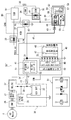
- FIG. 1 is an overall system diagram illustrating an FF plug-in hybrid vehicle to which a control device according to a first embodiment is applied. It is a power supply circuit diagram which shows the power supply system structure centering on the starter power supply of FF plug-in hybrid vehicle to which the control apparatus of Example 1 was applied. It is a block diagram which shows the control system structure of FF plug-in hybrid vehicle to which the control apparatus of Example 1 was applied. It is a flowchart which shows the flow of the capacitor charging / discharging control process performed with the hybrid control module of Example 1.
- FIG. 1 is an overall system diagram illustrating an FF plug-in hybrid vehicle to which a control device according to a first embodiment is applied. It is a power supply circuit diagram which shows the power supply system structure centering on the starter power supply of FF plug-in hybrid vehicle to which the control apparatus of Example 1 was applied. It is a block diagram which shows the control system structure of FF plug-in hybrid vehicle to which the control apparatus of Example 1 was applied. It is a flowchart which shows the flow
- the configuration of the FF plug-in hybrid vehicle (an example of a hybrid vehicle) to which the control device of the first embodiment is applied is described in detail as “drive system configuration”, “power supply system configuration”, “control system configuration”, and “capacitor charge / discharge control details”. The description will be divided into “configuration”.
- FIG. 1 shows the entire FF plug-in hybrid vehicle.
- the drive system configuration of the FF plug-in hybrid vehicle will be described with reference to FIG.
- the drive system includes a starter motor 1 (abbreviated as “M”), a horizontal engine 2 (abbreviated as “ICE”), a first clutch 3 (abbreviated as “CL1”), and a motor / generator. 4 (abbreviation “M / G”), a second clutch 5 (abbreviation “CL2”), and a belt type continuously variable transmission 6 (abbreviation “CVT”).
- M starter motor 1
- ICE horizontal engine 2
- CL1 first clutch 3
- CVT motor / generator. 4
- the output shaft of the belt type continuously variable transmission 6 is drivingly connected to the left and right front wheels 10R and 10L via a final reduction gear train 7, a differential gear 8, and left and right drive shafts 9R and 9L.
- the left and right rear wheels 11R and 11L are driven wheels.
- the starter motor 1 is a cranking motor that has a gear that meshes with an engine starting gear provided on a crankshaft of the horizontally placed engine 2 and that uses a capacitor 23 described later as a power source to rotate the crankshaft when the engine is started.
- the horizontal engine 2 is an engine disposed in the front room with the crankshaft direction as the vehicle width direction, and includes an electric water pump 12 and a crankshaft rotation sensor 13 that detects reverse rotation of the horizontal engine 2.
- the first clutch 3 is a hydraulic multi-plate friction clutch that is interposed between the horizontally mounted engine 2 and the motor / generator 4, and is fully engaged / slip engaged / released by the first clutch oil pressure.
- the motor / generator 4 is a three-phase AC permanent magnet type synchronous motor connected to the transverse engine 2 via the first clutch 3.
- the motor / generator 4 uses a high-power battery 21 described later as a power source, and an inverter 26 that converts direct current into three-phase alternating current during power running and converts three-phase alternating current into direct current during regeneration is connected to the stator coil. Connected through.
- the second clutch 5 is a wet-type multi-plate friction clutch by hydraulic operation that is interposed between the motor / generator 4 and the left and right front wheels 10R and 10L that are driving wheels. Slip fastening / release is controlled.
- the second clutch 5 of the first embodiment uses the forward clutch 5a and the reverse brake 5b provided in the forward / reverse switching mechanism of the belt-type continuously variable transmission 6 using planetary gears. That is, the forward clutch 5 a is the second clutch 5 during forward travel, and the reverse brake 5 b is the second clutch 5 during reverse travel.
- the belt type continuously variable transmission 6 is a transmission that obtains a continuously variable transmission ratio by changing the belt winding diameter by the transmission hydraulic pressure to the primary oil chamber and the secondary oil chamber.
- the belt-type continuously variable transmission 6 includes a main oil pump 14 (mechanical drive), a sub-oil pump 15 (motor drive), and a first pressure using a line pressure generated by adjusting pump discharge pressure as a primary pressure.
- a control valve unit (not shown) for generating the second clutch hydraulic pressure and the transmission hydraulic pressure.
- the first clutch 3, the motor / generator 4 and the second clutch 5 constitute a one-motor / two-clutch drive system, and there are “EV mode” and “HEV mode” as main drive modes by this drive system.
- the “EV mode” is an electric vehicle mode in which the first clutch 3 is disengaged and the second clutch 5 is engaged and only the motor / generator 4 is used as a drive source. Driving in the “EV mode” is referred to as “EV driving”. .
- the “HEV mode” is a hybrid vehicle mode in which both the clutches 3 and 5 are engaged and the horizontal engine 2 and the motor / generator 4 are used as driving sources, and traveling in the “HEV mode” is referred to as “HEV traveling”.
- the motor / generator 4 basically includes a regenerative cooperative brake unit 16 that controls the total braking torque when the brake is operated in accordance with the regenerative operation when the brake is operated.
- the regenerative cooperative brake unit 16 includes a brake pedal, an electric booster, and a master cylinder, and the electric booster shares a hydraulic braking force by subtracting the regenerative braking force from the required braking force that appears in the pedal operation amount when the brake is operated. In this way, cooperative control for regenerative / hydraulic pressure is performed.
- FIG. 1 shows an entire system of an FF plug-in hybrid vehicle
- FIG. 2 shows a power supply system configuration centering on a starter power supply.
- FIG.1 and FIG.2 the power supply system structure of FF plug-in hybrid vehicle is demonstrated.
- the power supply system includes a high-power battery 21 as a motor / generator power supply, a 12V battery 22 as a 12V system load power supply, and a capacitor 23 as a starter power supply.
- the high-power battery 21 is a secondary battery mounted as a power source for the motor / generator 4.
- a lithium ion battery in which a cell module in which a large number of cells are stacked is set in a battery pack case is used.
- the high-power battery 21 has a built-in junction box in which relay circuits for supplying / cutting off / distributing high-power are integrated, and further includes a battery temperature adjustment unit 24 having an air conditioner function, a battery charge capacity (battery SOC) and a battery. And a lithium battery controller 86 for monitoring the temperature.
- the high-power battery 21 and the motor / generator 4 are connected through a DC harness 25, an inverter 26, and an AC harness 27.
- the inverter 26 has a built-in junction box 28 in which relay circuits for supplying / cutting off / distributing strong power are integrated, and further includes a heating circuit 29, an electric air conditioner 30, and a motor controller 83 for performing power running / regenerative control. It is attached. That is, the inverter 26 converts a direct current from the DC harness 25 into a three-phase alternating current to the AC harness 27 during power running for driving the motor / generator 4 by discharging the high-power battery 21. Further, the three-phase alternating current from the AC harness 27 is converted into a direct current to the DC harness 25 during regeneration in which the high-power battery 21 is charged by power generation by the motor / generator 4.
- a rapid external charging port 32 is connected to the high-power battery 21 via a DC harness 31, and a normal external charging port 35 is connected via a DC branch harness 25 ′, a charger 33, and an AC harness 34. .
- the charger 33 performs AC / DC conversion and voltage conversion.
- the external charging is performed by connecting the connector plug of the charging stand installed in the place of going out to the rapid external charging port 32 (rapid external charging).
- rapid external charging external charging is performed by connecting a connector plug from a household power supply to the normal external charging port 35 (normal external charging), for example.
- the 12V battery 22 is a secondary battery mounted as a power source for a 12V system load 36, which is another auxiliary machine except the starter motor 1, for example, a lead battery generally mounted in an engine vehicle or the like. Is used.
- the high voltage battery 21 and the 12V battery 22 are connected via a DC branch harness 25 ′′, a DC / DC converter 37, and a battery harness 38.
- the DC / DC converter 37 changes the voltage of several hundred volts from the high voltage battery 21 to 12V.
- the DC / DC converter 37 is controlled by the hybrid control module 81 to manage the charge amount of the 12V battery 22.
- the capacitor 23 is an electricity storage device mounted as a dedicated power source for the starter motor 1 and has a large capacitance and an electric double layer capacitor (eDLC: electric Double Layer Capacitor) having excellent rapid charge / discharge performance. What is called is used.
- eDLC electric Double Layer Capacitor
- the auxiliary load power supply system 39 and the capacitor 23 are connected via a battery branch harness 38 ′ provided with a fuse 40 and a capacitor charging circuit 41.
- the capacitor 23 and the starter motor 1 are connected via a capacitor harness 42, a resistor 43, and a relay switch 44.
- the capacitor 23 and the capacitor charging circuit 41 constitute a DLC unit 45
- the starter motor 1 and the relay switch 44 constitute a starter unit 46.
- detailed configurations of the DLC unit 45 and the starter unit 46 will be described.
- the DLC unit 45 includes a capacitor 23, a capacitor charging circuit 41, a spontaneous discharge switch 47, a forced discharge switch 48, a cell voltage monitor 49, and a capacitor temperature sensor 50. I have.
- the capacitor 23 is configured by connecting a plurality of DLC cells in series / parallel.
- the spontaneous discharge switch 47, the forced discharge switch 48, and the capacitor temperature sensor 50 are provided at both ends of the plurality of DLC cells.
- the capacitor charging circuit 41 is constituted by a DC / DC converter circuit (a combination circuit of a switching element, a choke coil, a capacitor and a diode) with a built-in semiconductor relay by a switching method.
- the capacitor charging circuit 41 includes a semiconductor relay 51 and a DC / DC converter 52 that are controlled by a hybrid control module 81.
- the semiconductor relay 51 is a non-contact relay using a semiconductor switching element. For example, as schematically shown in the lower left part of FIG. 2, a light called a photocoupler that transmits an isolated input / output space with a light signal.
- the configuration uses a semiconductor.
- the semiconductor relay 51 has a switch function for disconnecting or connecting the capacitor 23 from the auxiliary load power supply system 38.
- the DC / DC converter 52 subdivides the input direct current into pulse currents by a switching element and connects them to obtain a direct current output of a necessary voltage, thereby converting a 12V direct current to a 13.5V direct current and a capacitor. Has a function to switch the charging current.
- the starter unit 46 includes a starter motor 1, a relay switch 43, an electromagnetic actuator 53, and a pinion shift mechanism 54.
- the electromagnetic actuator 53 turns on the relay switch 44 and shifts the pinion 57 of the pinion shift mechanism 54 to a position where it meshes with the ring gear 58 by electromagnetic force generated by energization of the two coils 55 and 56.
- the relay switch 44 is turned off and the pinion 57 is shifted to a position where the engagement with the ring gear 58 is released.
- the ring gear 58 is provided on the crankshaft of the horizontal engine 2.
- the auxiliary load power supply system 39 and the two coils 55 and 56 are connected via a battery branch harness 38 ′′ provided with a starter cut-off relay 59, a HEV / IS / relay 60, and a starter relay 61.
- Energization / cutoff of the off relay 59 is performed by a body control module 87.
- Energization / cutoff of the HEV / IS / relay 60 is performed by a hybrid control module 81.
- Energization / cutoff of the starter relay 61 is performed by an underhood switching module.
- the voltage sensor 62 for relay diagnosis is provided at a position where the battery branch harness 38 "intersects.
- the pinion shift mechanism 54 has a pinion 57 provided so as to be movable in the axial direction with respect to the motor shaft of the starter motor 1, one end connected to the electromagnetic actuator 53, and the other end fitted into the shift groove of the pinion 57. Shift lever 63.
- Control system configuration 1 shows an overall system of an FF plug-in hybrid vehicle
- FIG. 2 shows a power supply system configuration centering on a starter power supply
- FIG. 3 shows a control system configuration.
- the control system configuration of the FF plug-in hybrid vehicle will be described with reference to FIGS.
- the control system includes a hybrid control module 81 (abbreviation: “HCM”) as an integrated control means for properly managing the energy consumption of the entire vehicle.
- Control means connected to the hybrid control module 81 include an engine control module 82 (abbreviation: “ECM”), a motor controller 83 (abbreviation: “MC”), and a CVT control unit 84 (abbreviation: “CVTCU”).
- ECM engine control module
- MC motor controller
- CVT control unit 84 abbreviation: “CVTCU”.
- the data communication module 85 abbreviation: “DCM”
- the lithium battery controller 86 abbreviation: “LBC”
- BCM body control module
- USB underhood switching module
- CAN communication lines 90 CAN is an abbreviation of “Controller Area Network” except for a LIN communication line 89 (LIN: abbreviation of “Local Interconnection Network”) that connects the hybrid control module 81 and the DLC unit 45. Is connected so that bidirectional information can be exchanged.
- LIN abbreviation of “Local Interconnection Network”
- the hybrid control module 81 performs various controls based on input information from each control means, an ignition switch 91, an accelerator opening sensor 92, a vehicle speed sensor 93, and the like. Among these, the control performed for the purpose of driving the FF plug-in hybrid vehicle capable of external charging with high fuel efficiency is a travel mode based on the battery SOC of the high-power battery 21 (“CD mode”, “CS mode”). Selection control.
- the “CD mode (Charge Depleting mode)” is a mode in which priority is given to EV running that consumes the power of the high-power battery 21 in principle. For example, while the battery SOC of the high-power battery 21 decreases from full SOC to set SOC. Is selected. However, HEV traveling is exceptionally performed in high-load traveling where driving force is insufficient in EV traveling.
- the start of the horizontal engine 2 during the selection of the “CD mode” is based on the start by the starter motor 1 (starter start), with the exception of the start by the motor / generator 4 (M / G start).
- the “CS mode (Charge Sustain mode)” is a mode in which priority is given to HEV traveling that maintains the power of the high-power battery 21 in principle, and is selected when the battery SOC of the high-power battery 21 is equal to or lower than the set SOC. That is, when it is necessary to maintain the battery SOC of the high-power battery 21 within a predetermined range, HEV traveling is performed by engine power generation that causes the motor / generator 4 to generate electric power by driving the lateral engine 2.
- the start of the horizontal engine 2 during the selection of the “CS mode” is based on the start by the motor / generator 4 (M / G start), with the exception of the start by the starter motor 1 (starter start).
- the “set SOC” that is the mode switching threshold value has hysteresis between the threshold value in the CD mode ⁇ CS mode and the threshold value in the CS mode ⁇ CD mode.
- the hybrid control module 81 performs engine start control by the starter motor 1, charge control to the capacitor 23, and discharge control from the capacitor 23 in addition to the selection control of “CD mode” and “CS mode”. Furthermore, the following starter start related control is performed.
- A Time-saving control from engine start to starter start permission.
- B Time shortening control from ignition on to starter start permission.
- C Deterioration progress suppression control of the capacitor 23 (Example 1).
- D Control of countermeasures for high / low temperature of capacitor 23.
- E Prevention of voltage sag of auxiliary equipment for vehicles.
- the engine control module 82 performs fuel injection control, ignition control, fuel cut control, and the like of the horizontally placed engine 2.
- the motor controller 83 performs power running control, regeneration control, and the like of the motor generator 4 by the inverter 26.
- the CVT control unit 84 performs engagement hydraulic pressure control of the first clutch 3, engagement hydraulic pressure control of the second clutch 5, shift hydraulic pressure control of the belt type continuously variable transmission 6, and the like.
- the data communication module 85 controls, for example, lock / unlock of the charging port lid and the connector lock mechanism.
- the lithium battery controller 86 manages the battery SOC, battery temperature, and the like of the high-power battery 21.
- the body control module 87 performs energization / cutoff control of the starter cut-off relay 59.
- the under hood switching module 87 performs energization / cut-off control of the built-in starter relay 61 based on the range position signal from the inhibitor switch 94.
- FIG. 4 shows a capacitor charge / discharge control processing flow executed by the hybrid control module 81 (capacitor charge / discharge control means).
- the hybrid control module 81 capacitor charge / discharge control means
- step S1 it is determined whether or not the EV mode is selected in which the EV mode using the motor / generator 4 as a drive source is selected. If Yes (EV traveling), the process proceeds to step S2, and if No (HEV traveling), the process proceeds to the end.
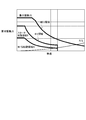
- step S2 following the determination that the vehicle is traveling in EV in step S1, the engine start region map shown in FIG. 5 is searched, and the operating point based on the vehicle speed and the required driving force (for example, accelerator opening) is determined as the engine start region. It is determined whether or not it exists in the M / G start area A on the map. If Yes (exists in the M / G start area A), the process proceeds to step S3. If No (exists in the starter start area B), the process proceeds to step S6.
- the engine start area map as shown in FIG. 5, an area obtained by subtracting the engine cranking necessary torque from the EV area based on the maximum motor output torque characteristic with respect to the vehicle speed is set as the M / G start area A.
- the EV range based on the maximum motor output torque characteristic with respect to the vehicle speed is originally the starter start region, but the region obtained by subtracting the M / G start region A from the EV region in accordance with the setting of the M / G start region.
- the starter start area B is set (engine start area map setting means).
- step S3 it is determined whether or not the capacitor voltage is equal to or lower than the voltage b at which the deterioration does not proceed, following the determination that the capacitor is present in the M / G start region A in step S2. If Yes (capacitor voltage ⁇ voltage b), the process proceeds to the end. If No (capacitor voltage> voltage b), the process proceeds to step S4.
- the “voltage b at which the deterioration does not proceed” it has been found that the deterioration does not proceed if the voltage is 1 V or less per cell of the capacitor 23. For example, when six cells are connected in series, the deterioration due to the increase in the internal resistance. Is set to 6.0V, which suppresses the progress of.
- step S4 following the determination that capacitor voltage> voltage b in step S3 or step S5, the forced discharge switch 48 is closed to forcibly discharge the capacitor 23, and the process proceeds to step S5.
- the capacitor forced discharge is performed by, for example, a current 3 that is a normal discharge current.
- step S5 following the capacitor forced discharge in step S4, it is determined whether or not the capacitor voltage is equal to or lower than a voltage b at which deterioration does not proceed. If Yes (capacitor voltage ⁇ voltage b), the process proceeds to the end. If No (capacitor voltage> voltage b), the process returns to step S4.
- the same voltage value as in step S3 is used for “voltage b at which deterioration does not proceed”.
- step S6 it is determined whether or not the capacitor voltage is equal to or higher than the starter start permission voltage a following the determination that the starter start region B exists in step S2. If Yes (capacitor voltage ⁇ starter start permission voltage a), the process proceeds to the end. If No (capacitor voltage ⁇ starter start permission voltage a), the process proceeds to step S7.
- the “starter start permission voltage a” is set to about 12.5 V within which the required starter start time is within the target time in the case of the capacitor 23 having a full charge and a capacitor voltage of 13.5 V in the first embodiment, for example. .
- step S7 following the determination that capacitor voltage ⁇ starter start permission voltage a in step S6 or step S8, normal current 1 (for example, 15 A) that suppresses capacitor deterioration is selected as the charging current, and current 1
- normal current 1 for example, 15 A
- step S8 following the capacitor recharge in step S7, it is determined whether or not the capacitor voltage is equal to or higher than the starter start permission voltage a. If Yes (capacitor voltage ⁇ starter start permission voltage a), the process proceeds to the end. If No (capacitor voltage ⁇ starter start permission voltage a), the process returns to step S7.
- the “starter start permission voltage a” uses the same value as in step S6.
- the operation of the control device for the FF plug-in hybrid vehicle of the first embodiment is divided into [characteristic operation by the capacitor power circuit configuration], [charge / discharge operation by the capacitor power supply], and [capacitor charge / discharge control operation during EV travel]. To do.
- the power supply circuit configuration is a configuration in which the DLC unit 45 and the fuse 40 are removed from the capacitor power supply circuit configuration of the first embodiment. To do.
- the power supply of the starter motor and the vehicle auxiliary machines is shared by one 12V battery. For this reason, if the starter motor is used to start the engine when the required amount of power in the vehicle auxiliaries is high, the supply power is insufficient, and the voltage of the vehicle auxiliaries decreases suddenly at the moment of starting the engine. Low occurs.
- the auxiliary load power supply system 39 is configured by connecting the high voltage battery 21 and the 12V battery 22 via the DC / DC converter 37.
- the DLC unit 45 includes a capacitor charging circuit 41 that is branched and connected from the DC / DC converter 37 and a capacitor 23 that is connected to the capacitor charging circuit 41.
- a capacitor power supply circuit is configured by providing a semiconductor relay 51 as a switch built in the capacitor charging circuit 41 between the auxiliary load power supply system 39 and the DLC unit 45.
- the 12V battery 22 and the capacitor 23 are charged with the electric power from the high-power battery 21, and the necessary power is supplied from the 12V battery 22 to the 12V system load 36, which is a vehicle auxiliary device.
- the starter motor 1 and the 12V system load 36 do not share the power source, and the two power sources including the 12V battery 22 and the capacitor 23 receive a charge backup by the high-power battery 21.
- the capacitor power supply circuit is configured by adding the DLC unit 45 (capacitor charging circuit 41 + capacitor 23) without changing the power supply circuit configuration of the idle stop vehicle which is the comparative example.
- the DLC unit 45 can be added in the same manner as the addition of auxiliary equipment, the control of the high-power battery 21 and the DC / DC converter 37 does not need to be changed from the control of the comparative example.
- the DLC unit 45 (capacitor charging circuit 41 + capacitor 23) can control the charging current and the auxiliary relay load by the semiconductor relay 51 as a switch.
- the power supply system 39 can be disconnected. For this reason, by opening the semiconductor relay 51 at the start of the starter, it is possible to prevent a voltage sag in which the voltage of the vehicle auxiliary machinery suddenly decreases.
- the engine start by the starter motor 1 is based on the output of the starter start command from the hybrid control module 81.
- the relay switch 44 is turned on and the pinion 57 is shifted to a position where it engages with the ring gear 58. To do.
- the starter motor 1 using the capacitor 23 as a power source rotates the crankshaft of the horizontal engine 2 to start the starter, and the HEV / IS / relay 60 is cut off after a predetermined time from energization.
- the starter cut-off relay 59 is energized by the body control module 87 except when a vehicle condition prohibiting engine start is satisfied.
- the starter relay 61 built in the underhood switching module 88 is energized only when the P range is selected, and is in a cut-off state when a D range other than the P range is selected. Therefore, in principle, the engine start control by the starter motor 1 is performed by using the power of the capacitor 23 while the HEV / IS / relay 60 is energized by the starter start command under the starter start permission condition. Then, the horizontal engine 2 is started (starter start control means).
- the horizontal engine 2 can be started by using a motor / generator 4 that uses a high-power battery 21 as a power source and cranking the horizontal engine 2 to start M / G.
- the second clutch 5 is brought into a slip engagement state, and the first clutch 3 is gradually engaged, whereby the motor / generator 4 is used as a starter motor and the transverse engine 2 is cranked ( M / G start control means).
- the semiconductor relay 51 of the capacitor charging circuit 41 is closed based on the output of the charging command from the hybrid control module 81, and the capacitor charging current is selected.
- the electric power from the high-power battery 21 is introduced into the capacitor 23 through the DC / DC converter 37 ⁇ the fuse 40 ⁇ the semiconductor relay 51 ⁇ the DC / DC converter 52, so that the short-time charging according to the capacitor charging current can be performed.
- the capacitor charging current has a current 1 (for example, 15 A) as a basic current, and has a current 2 (for example, 20 A) that can be selected by changing from the current 1 as an exception. Therefore, the charging control to the capacitor 23 uses the power from the high-power battery 21 and charges the capacitor 23 with the selected capacitor charging current while the charging command is output.
- the discharge from the capacitor 23 causes the natural discharge from the capacitor 23 by closing the natural discharge switch 47 of the DLC unit 45. Further, the forced discharge from the capacitor 23 is performed by closing the forced discharge switch 48 of the DLC unit 45 based on the output of the forced discharge command from the hybrid control module 81.
- the discharge amount per unit time is set larger than that in the case of natural discharge. Therefore, in the forced discharge control to the capacitor 23, while the forced discharge switch 48 is closed based on the forced discharge command, the power of the capacitor 23 is converted into resistance heat, and discharge is performed in a shorter time than natural discharge.
- the capacitor discharge current the current 3 is a basic current, and the current 4 is larger than the current 3 as an exception. Therefore, the forced discharge control to the capacitor 23 is discharged from the high-power battery 21 by the selected capacitor discharge current while the discharge command is output.
- EV mode is an electric vehicle mode in which the first clutch 3 is released, the second clutch 5 is engaged, and only the motor / generator 4 is used as a drive source.
- HEV mode is a hybrid vehicle mode in which both the clutches 3 and 5 are engaged and the transverse engine 2 and the motor / generator 4 are used as drive sources.
- starter start in which the horizontal engine 2 is started by the starter motor 1
- M / G start in which the horizontal engine 2 is started by the motor / generator 4.
- the M / G torque of the motor / generator 4 can be all directed to EV travel.
- the motor / generator 4 can be used and the horizontally mounted engine 2 can be started by cranking, so there is no need to use starter start.
- starter start is used, if the capacitor 23 is kept fully charged in preparation for a starter start request, the internal resistance increases and capacitor deterioration progresses.
- the capacitor voltage is maintained at a voltage b or less at which deterioration does not proceed, thereby allowing the capacitor 23 Priority can be given to suppressing the progress of deterioration. Therefore, when the EV mode is selected, priority is given to prevention of capacitor deterioration when the operating point is in the M / G starting area A, and priority is given to starter starting only when the operating point is out of the M / G starting area A. .
- the capacitor charge / discharge control action during EV travel reflecting this will be described.
- step S1 ⁇ step S2 in the flowchart of FIG. Step S3 ⁇ End is repeated. Further, when the operating point enters the M / G start area A from the starter start area B and the capacitor voltage is higher than the voltage b at which deterioration does not proceed, step S1 ⁇ step S2 ⁇ step S3 ⁇ The process proceeds from step S4 to step S5.
- step S5 while it is determined in step S5 that the capacitor voltage is higher than the voltage b at which the deterioration does not proceed, the flow from step S4 to step S5 is repeated, and the capacitor forced discharge is performed in step S4. That is, when the operating point enters the M / G starting region A, the capacitor is forcibly discharged. When the operating point exists in the M / G starting region A, the capacitor voltage is maintained at a voltage b or less at which deterioration does not proceed.
- step S1 when the EV is running and the operating point exists in the starter start region B and the capacitor voltage is equal to or higher than the starter start permission voltage a, step S1 ⁇ step S2 ⁇ step S6 ⁇ The flow to the end is repeated.
- step S1, step S2, step S6, step The process proceeds from S7 to step S8.
- step S8 while it is determined in step S8 that the capacitor voltage is less than the starter start permission voltage a, the flow from step S7 to step S8 is repeated, and the capacitor is recharged in step S7. That is, when the operating point enters the starter start region B, the capacitor is recharged.
- the capacitor voltage is maintained at the starter start permission voltage a or higher.
- the capacitor voltage is maintained at a voltage b or less at which deterioration does not proceed.
- a configuration is adopted in which the capacitor voltage is recharged to a starter start permission voltage a or higher (steps S1 to S8 in FIG. 4).
- the capacitor voltage that is equal to or higher than the starter start permission voltage a is maintained. That is, when it exists in the starter start region B, the capacitor voltage (starter start permission voltage a or higher) giving priority to starter start is maintained. Therefore, when the vehicle is present in the starter start region B during EV travel, the horizontally placed engine 2 can be started in response to the starter start request with good response.
- the capacitor voltage is forcibly discharged until the starter start permission voltage a becomes higher than the voltage b where deterioration does not proceed. Is adopted (steps S3 to S5 in FIG. 4). That is, from the starter start permission voltage a to the voltage b where the deterioration does not proceed, the gap between the capacitor voltages increases, and it takes a long time to wait until the capacitor voltage decreases due to natural discharge.
- the capacitor voltage is quickly lowered to a voltage b or less at which the deterioration does not proceed, and the progress of the capacitor deterioration can be further suppressed.
- the drive system has a starter motor 1, an engine (horizontal engine 2), and a motor / generator 4.
- a high-power battery 21 as a power source of the motor / generator 4
- a capacitor 23 as a power source of the starter motor 1
- capacitor charge / discharge control means for controlling charge / discharge of the capacitor 23.
- a control device for a hybrid vehicle comprising: Starter start control means (hybrid control module 81) for starting the starter by cranking the engine (horizontal engine 2) using the starter motor 1 using the capacitor 23 as a power source; M / G start control means (hybrid control module 81) for cranking the engine (horizontal engine 2) and starting M / G using the motor / generator 4 powered by the high-power battery 21; Engine start area map where M / G start area A is the area obtained by subtracting the engine cranking required torque from the EV area based on the maximum motor output torque characteristics with respect to the vehicle speed when the EV mode using motor / generator 4 as the drive source is selected.
- Engine starting area map setting means FIG.
- the capacitor charge / discharge control means (hybrid control module 81), when the operating point due to the vehicle speed and the required driving force exists in the M / G start area A, the voltage b at which the deterioration of the capacitor voltage does not proceed.
- the capacitor voltage is recharged to a starter start permission voltage a or higher (FIG. 4).
- a starter start permission voltage a or higher FOG. 4
- the capacitor charge / discharge control means (hybrid control module 81) has a starter start permission voltage a when the operating point based on the vehicle speed and the required driving force exists in the starter start region B that is out of the M / G start region A.
- the above capacitor voltage is maintained (FIG. 4). For this reason, in addition to the effect of (1), the horizontal engine 2 can be started in response to the starter start request with good response when it exists in the starter start region B during EV traveling.
- the capacitor charge / discharge control means (hybrid control module 81) deteriorates the capacitor voltage from the starter start permission voltage a or higher when the operating point by the vehicle speed and the required driving force enters the M / G start area A. Is forcibly discharged until the voltage b becomes lower than the voltage b (FIG. 4). For this reason, in addition to the effect of (1) or (2), when the operating point enters the M / G start region A, the capacitor voltage quickly decreases to a voltage b or less at which deterioration does not proceed, and the capacitor deterioration proceeds. Can be further suppressed.
- the hybrid vehicle control device of the present invention has been described based on the first embodiment. However, the specific configuration is not limited to the first embodiment, and the invention according to each claim of the claims is described. Design changes and additions are allowed without departing from the gist.
- the capacitor charge / discharge control means when the EV mode is selected, when the operating point exists in the M / G start region A, the capacitor voltage is maintained below the voltage b at which deterioration does not proceed, and the operating point is M In the example, the capacitor voltage is recharged up to the starter start permission voltage a or higher when it is out of the / G start region A.
- the capacitor charge / discharge control means may be an example of maintaining the capacitor voltage of 0V when the operating point is in the M / G start area A when the EV mode is selected. Further, when the operating point deviates from the M / G start area A, the capacitor voltage may be recharged to full charge.
- Example 1 as an example of the capacitor charge / discharge control means, recharge or forced discharge control is performed using travel mode information and capacitor voltage information.
- Example 1 shows an example in which the hybrid control module 81 is used as the capacitor charge / discharge control means.
- the capacitor charge / discharge control means an independent power supply system controller may be used, or an example in which a power supply system capacitor charge / discharge control unit is provided in a controller other than the hybrid control module may be used. .
- Example 1 shows an example in which the control device of the present invention is applied to an FF plug-in hybrid vehicle.
- the control device of the present invention can be applied not only to FF plug-in hybrid vehicles but also to FF hybrid vehicles, FR hybrid vehicles, and 4WD hybrid vehicles that do not have a function of externally charging a high-power battery.
- it can be applied to any hybrid vehicle that includes a capacitor as a starter power source and is capable of starter start and M / G start as an engine start method.
Abstract
Description
このハイブリッド車両の制御装置において、スタータ始動制御手段と、M/G始動制御手段と、エンジン始動領域マップ設定手段と、を設ける。
前記スタータ始動制御手段は、前記キャパシタを電源とするスタータモータを用い、前記エンジンをクランキングしてスタータ始動する。
前記M/G始動制御手段は、前記強電バッテリを電源とするモータ/ジェネレータを用い、前記エンジンをクランキングしてM/G始動する。
前記エンジン始動領域マップ設定手段は、前記モータ/ジェネレータを駆動源とするEVモードの選択時、車速に対する最大モータ出力トルク特性によるEV領域からエンジンクランキング必要分トルクを差し引いた領域をM/G始動領域とするエンジン始動領域マップを設定する。
前記キャパシタ充放電制御手段は、EVモードの選択時、車速と要求駆動力による動作点が前記M/G始動領域に存在するとき、キャパシタ電圧を劣化が進行しない電圧以下に維持し、車速と要求駆動力による動作点が前記M/G始動領域から外れたとき、キャパシタ電圧をスタータ始動許可電圧以上まで再充電する。
すなわち、キャパシタを電源とするスタータ始動によって、M/Gトルクを全てEV走行に振り向けることができる。しかし、M/G始動領域では、モータ/ジェネレータを用い、エンジンをクランキングできるので、スタータ始動を用いる必要が無い。このため、車速と要求駆動力による動作点がM/G始動領域から外れてスタータ始動領域に入らない限り、キャパシタ電圧を、劣化が進行しない電圧以下に維持しておくことで、キャパシタの劣化進行を抑えることを優先できる。
よって、EVモードの選択時、動作点がM/G始動領域に存在するとき、キャパシタ電圧を劣化が進行しない電圧以下に維持し、動作点がM/G始動領域から外れたとき、キャパシタ電圧をスタータ始動許可電圧以上まで再充電する。
この結果、EVモードの選択時、エンジン始動を確保しながら、キャパシタの劣化進行を抑制することができる。
実施例1の制御装置が適用されたFFプラグインハイブリッド車両(ハイブリッド車両の一例)の構成を、「駆動システム構成」、「電源システム構成」、「制御システム構成」、「キャパシタ充放電制御の詳細構成」に分けて説明する。
図1はFFプラグインハイブリッド車両の全体を示す。以下、図1に基づいて、FFプラグインハイブリッド車両の駆動システム構成を説明する。
図1はFFプラグインハイブリッド車両の全体システムを示し、図2はスタータ電源を中心とする電源システム構成を示す。以下、図1及び図2に基づいて、FFプラグインハイブリッド車両の電源システム構成を説明する。
図1はFFプラグインハイブリッド車両の全体システムを示し、図2はスタータ電源を中心とする電源システム構成を示し、図3は制御システム構成を示す。以下、図1~図3に基づいて、FFプラグインハイブリッド車両の制御システム構成を説明する。
(A)エンジン始動後からスタータ始動許可までの時間短縮制御。
(B)イグニッションオンからスタータ始動許可までの時間短縮制御。
(C)キャパシタ23の劣化進行抑制制御(実施例1)。
(D)キャパシタ23の高温/低温時対策制御。
(E)車両用補機の電圧瞬低防止制御。
図4はハイブリッドコントロールモジュール81にて実行されるキャパシタ充放電制御処理流れを示す(キャパシタ充放電制御手段)。以下、キャパシタ充放電制御処理構成をあらわす図4の各ステップについて説明する。
ここで、エンジン始動領域マップは、図5に示すように、車速に対する最大モータ出力トルク特性によるEV領域からエンジンクランキング必要分トルクを差し引いた領域をM/G始動領域Aとして設定している。そして、車速に対する最大モータ出力トルク特性によるEV領域は、本来、全域がスタータ始動領域であるが、M/G始動領域を設定したことに伴いEV領域からM/G始動領域Aを差し引いた領域を、スタータ始動領域Bとして設定している(エンジン始動領域マップ設定手段)。
ここで、「劣化が進行しない電圧b」としては、キャパシタ23の1セルあたり1V以下であれば劣化が進行しないことがわかったので、例えば、6セルを直列した場合、内部抵抗の増加による劣化の進行が抑えられる6.0Vに設定される。
ここで、キャパシタ強制放電は、例えば、通常の放電電流である電流3により行われる。
ここで、「劣化が進行しない電圧b」は、ステップS3と同じ電圧値が用いられる。
ここで、「スタータ始動許可電圧a」は、例えば、実施例1の満充電でキャパシタ電圧が13.5Vのキャパシタ23の場合、スタータ始動の所要時間が目標時間内になる12.5V程度に設定される。
ここで、「スタータ始動許可電圧a」は、ステップS6と同じ値を用いる。
実施例1のFFプラグインハイブリッド車両の制御装置における作用を、[キャパシタ電源回路構成による特徴作用]、[キャパシタ電源による充放電作用]、[EV走行時のキャパシタ充放電制御作用]に分けて説明する。
例えば、アイドルストップ車において、スタータモータの電源を12Vバッテリとする場合、電源回路構成は、実施例1のキャパシタ電源回路構成からDLCユニット45とヒューズ40を除いた構成とされ、これを比較例とする。
上記キャパシタ電源回路に対しハイブリッドコントロールモジュール81により行われる「スタータモータ1によるエンジン始動制御作用」、「キャパシタ23への充電制御作用」、「キャパシタ23からの放電制御作用」を説明する。
したがって、スタータモータ1によるエンジン始動制御は、原則として、スタータ始動許可条件下でのスタータ始動指令によりHEV/IS/リレー60が通電されている間、キャパシタ23の電力を用いてスタータモータ1が駆動し、横置きエンジン2を始動させる(スタータ始動制御手段)。
なお、横置きエンジン2の始動には、強電バッテリ21を電源とするモータ/ジェネレータ4を用い、横置きエンジン2をクランキングしてM/G始動する制御がある。このM/G始動制御では、第2クラッチ5をスリップ締結状態とし、第1クラッチ3を徐々に締結していくことで、モータ/ジェネレータ4をスタータモータとし、横置きエンジン2をクランキングする(M/G始動制御手段)。
したがって、キャパシタ23への充電制御は、充電指令が出力されている間、強電バッテリ21からの電力を用い、選択されているキャパシタ充電電流によりキャパシタ23を充電する。
したがって、キャパシタ23への強制放電制御は、強制放電指令に基づいて強制放電用スイッチ48を閉としている間、キャパシタ23の電力を抵抗熱に変換し、自然放電よりも短時間にて放電を行う。なお、キャパシタ放電電流としては、電流3を基本電流とし、例外として、電流3より大きい電流4を有する。
したがって、キャパシタ23への強制放電制御は、放電指令が出力されている間、強電バッテリ21から、選択されているキャパシタ放電電流により放電する。
上記のように、1モータ・2クラッチの駆動システムの場合、駆動モードとして「EVモード」と「HEVモード」の何れかが選択される。「EVモード」は、第1クラッチ3を開放し、第2クラッチ5を締結してモータ/ジェネレータ4のみを駆動源に有する電気自動車モードである。一方、「HEVモード」は、両クラッチ3,5を締結して横置きエンジン2とモータ/ジェネレータ4を駆動源に有するハイブリッド車モードである。
すなわち、EVモードの選択時、動作点がM/G始動領域Aに存在するとき、劣化防止を優先し、動作点がM/G始動領域から外れたとき、素早くスタータ始動に備えるスタータ始動を優先するようにしている。
この結果、EVモードの選択時、M/G始動又はスタータ始動によるエンジン始動を確保しながら、キャパシタ23の劣化進行を抑制することができる。
すなわち、スタータ始動領域Bに存在するときには、スタータ始動を優先するキャパシタ電圧(スタータ始動許可電圧a以上)を維持している。
したがって、EV走行中にスタータ始動領域Bに存在するとき、スタータ始動要求に応答良く対応して横置きエンジン2を始動することができる。
すなわち、スタータ始動許可電圧a以上から劣化が進行しない電圧b以下までは、キャパシタ電圧の乖離幅が大きくなり、自然放電によりキャパシタ電圧が低下するまで待つと長時間を要する。
これに対し、動作点がM/G始動領域Aへ入ったことで、キャパシタ電圧を、スタータ始動許可電圧a以上から劣化が進行しない電圧b以下まで低下させる際、強制放電を用いた。このため、キャパシタ電圧が、劣化が進行しない電圧b以下まで早期に低下し、キャパシタ劣化の進行をより抑えることができる。
実施例1のFFプラグインハイブリッド車両の制御装置にあっては、下記に列挙する効果を得ることができる。
電源システムとして、前記モータ/ジェネレータ4の電源である強電バッテリ21と、前記スタータモータ1の電源であるキャパシタ23と、前記キャパシタ23の充放電を制御するキャパシタ充放電制御手段(ハイブリッドコントロールモジュール81)と、を備えたハイブリッド車両(FFプラグインハイブリッド車両)の制御装置において、
前記キャパシタ23を電源とするスタータモータ1を用い、前記エンジン(横置きエンジン2)をクランキングしてスタータ始動するスタータ始動制御手段(ハイブリッドコントロールモジュール81)と、
前記強電バッテリ21を電源とするモータ/ジェネレータ4を用い、前記エンジン(横置きエンジン2)をクランキングしてM/G始動するM/G始動制御手段(ハイブリッドコントロールモジュール81)と、
前記モータ/ジェネレータ4を駆動源とするEVモードの選択時、車速に対する最大モータ出力トルク特性によるEV領域からエンジンクランキング必要分トルクを差し引いた領域をM/G始動領域Aとするエンジン始動領域マップを設定するエンジン始動領域マップ設定手段(図5)と、を設け、
前記キャパシタ充放電制御手段(ハイブリッドコントロールモジュール81)は、EVモードの選択時、車速と要求駆動力による動作点が前記M/G始動領域Aに存在するとき、キャパシタ電圧を劣化が進行しない電圧b以下に維持し、車速と要求駆動力による動作点が前記M/G始動領域Aから外れたとき、キャパシタ電圧をスタータ始動許可電圧a以上まで再充電する(図4)。
このため、EVモードの選択時、横置きエンジン2のエンジン始動を確保しながら、キャパシタ23の劣化進行を抑制することができる。加えて、必要なときにだけキャパシタ23を充電するため、12V系電源の充放電バランスに余裕ができる。
このため、(1)の効果に加え、EV走行中にスタータ始動領域Bに存在するとき、スタータ始動要求に応答良く対応して横置きエンジン2を始動することができる。
このため、(1)又は(2)の効果に加え、動作点がM/G始動領域Aへ入ったとき、キャパシタ電圧が、劣化が進行しない電圧b以下まで早期に低下し、キャパシタ劣化の進行をより抑えることができる。
Claims (3)
- 駆動系にスタータモータとエンジンとモータ/ジェネレータを有し、
電源システムとして、前記モータ/ジェネレータの電源である強電バッテリと、前記スタータモータの電源であるキャパシタと、前記キャパシタの充放電を制御するキャパシタ充放電制御手段と、を備えるハイブリッド車両の制御装置において、
前記キャパシタを電源とするスタータモータを用い、前記エンジンをクランキングしてスタータ始動するスタータ始動制御手段と、
前記強電バッテリを電源とするモータ/ジェネレータを用い、前記エンジンをクランキングしてM/G始動するM/G始動制御手段と、
前記モータ/ジェネレータを駆動源とするEVモードの選択時、車速に対する最大モータ出力トルク特性によるEV領域からエンジンクランキング必要分トルクを差し引いた領域をM/G始動領域とするエンジン始動領域マップを設定するエンジン始動領域マップ設定手段と、を設け、
前記キャパシタ充放電制御手段は、EVモードの選択時、車速と要求駆動力による動作点が前記M/G始動領域に存在するとき、キャパシタ電圧を劣化が進行しない電圧以下に維持し、車速と要求駆動力による動作点が前記M/G始動領域から外れたとき、キャパシタ電圧をスタータ始動許可電圧以上まで再充電する
ことを特徴とするハイブリッド車両の制御装置。 - 請求項1に記載されたハイブリッド車両の制御装置において、
前記キャパシタ充放電制御手段は、車速と要求駆動力による動作点が前記M/G始動領域から外れたスタータ始動領域に存在するとき、スタータ始動許可電圧以上のキャパシタ電圧を維持する
ことを特徴とするハイブリッド車両の制御装置。 - 請求項1又は2に記載されたハイブリッド車両の制御装置において、
前記キャパシタ充放電制御手段は、車速と要求駆動力による動作点が前記M/G始動領域へ入ったとき、キャパシタ電圧を、スタータ始動許可電圧以上から劣化が進行しない電圧以下になるまで強制放電する
ことを特徴とするハイブリッド車両の制御装置。
Priority Applications (4)
| Application Number | Priority Date | Filing Date | Title |
|---|---|---|---|
| EP14807276.2A EP3006293B1 (en) | 2013-06-03 | 2014-03-26 | Hybrid vehicle control device |
| JP2015521323A JP5979316B2 (ja) | 2013-06-03 | 2014-03-26 | ハイブリッド車両の制御装置 |
| US14/787,929 US9452753B2 (en) | 2013-06-03 | 2014-03-26 | Control system for a plug-in hybrid vehicle |
| CN201480031916.1A CN105263774B (zh) | 2013-06-03 | 2014-03-26 | 混合动力车辆的控制装置 |
Applications Claiming Priority (2)
| Application Number | Priority Date | Filing Date | Title |
|---|---|---|---|
| JP2013117183 | 2013-06-03 | ||
| JP2013-117183 | 2013-06-03 |
Publications (1)
| Publication Number | Publication Date |
|---|---|
| WO2014196244A1 true WO2014196244A1 (ja) | 2014-12-11 |
Family
ID=52007900
Family Applications (1)
| Application Number | Title | Priority Date | Filing Date |
|---|---|---|---|
| PCT/JP2014/058510 WO2014196244A1 (ja) | 2013-06-03 | 2014-03-26 | ハイブリッド車両の制御装置 |
Country Status (5)
| Country | Link |
|---|---|
| US (1) | US9452753B2 (ja) |
| EP (1) | EP3006293B1 (ja) |
| JP (1) | JP5979316B2 (ja) |
| CN (1) | CN105263774B (ja) |
| WO (1) | WO2014196244A1 (ja) |
Cited By (4)
| Publication number | Priority date | Publication date | Assignee | Title |
|---|---|---|---|---|
| CN106080448A (zh) * | 2016-07-29 | 2016-11-09 | 深圳市品川能源电气有限公司 | 一种封装有dc模块和充电模块的电动车高压配电控制箱 |
| CN106394273A (zh) * | 2015-07-30 | 2017-02-15 | 丰田自动车株式会社 | 用于车辆的电源系统 |
| US11059472B2 (en) | 2017-12-22 | 2021-07-13 | Subaru Corporation | Control device of vehicle and control method of vehicle |
| US11065974B2 (en) * | 2018-04-12 | 2021-07-20 | Toyota Jidosha Kabushiki Kaisha | Control system for autonomous vehicle |
Families Citing this family (8)
| Publication number | Priority date | Publication date | Assignee | Title |
|---|---|---|---|---|
| CN105246751B (zh) * | 2013-05-29 | 2017-05-10 | 日产自动车株式会社 | 插电混合动力车辆的控制装置 |
| EP3006293B1 (en) * | 2013-06-03 | 2017-05-24 | Nissan Motor Company, Limited | Hybrid vehicle control device |
| KR101526432B1 (ko) * | 2014-07-31 | 2015-06-05 | 현대자동차 주식회사 | 하이브리드 차량의 회생 제동량 연산 장치 및 방법 |
| CN106541943B (zh) * | 2016-11-08 | 2019-07-05 | 潍柴动力股份有限公司 | 一种混联式新能源动力总成、汽车动力系统及控制方法 |
| US10479220B2 (en) * | 2017-04-11 | 2019-11-19 | GM Global Technology Operations LLC | Hybrid powertrain with dual energy storage devices |
| US11117484B2 (en) * | 2018-05-09 | 2021-09-14 | Byton Limited | Safe and secure charging of a vehicle |
| CN110329076B (zh) * | 2019-08-08 | 2024-02-27 | 河南职业技术学院 | 一种混合动力工程机械车辆电能控制系统的控制方法 |
| JP7268626B2 (ja) * | 2020-03-12 | 2023-05-08 | トヨタ自動車株式会社 | ハイブリッド車両の駆動システム |
Citations (6)
| Publication number | Priority date | Publication date | Assignee | Title |
|---|---|---|---|---|
| JPH05328530A (ja) * | 1992-03-16 | 1993-12-10 | Toyota Motor Corp | ハイブリッド車用電源装置 |
| JP2007098977A (ja) * | 2005-09-30 | 2007-04-19 | Panasonic Ev Energy Co Ltd | 二次電池用の制御装置及び二次電池の出力制御方法 |
| JP2008141855A (ja) | 2006-12-01 | 2008-06-19 | Matsushita Electric Ind Co Ltd | 蓄電装置 |
| JP2012167627A (ja) * | 2011-02-16 | 2012-09-06 | Nissan Motor Co Ltd | エンジンの始動装置 |
| JP2012250676A (ja) * | 2011-06-07 | 2012-12-20 | Nissan Motor Co Ltd | ハイブリッド車両のエンジン始動制御装置 |
| WO2013038857A1 (ja) * | 2011-09-14 | 2013-03-21 | 日産自動車株式会社 | ハイブリッド車両の制御装置 |
Family Cites Families (15)
| Publication number | Priority date | Publication date | Assignee | Title |
|---|---|---|---|---|
| US7290627B1 (en) * | 1992-04-13 | 2007-11-06 | Conrad Oliver Gardner | Extended range motor vehicle having ambient pollutant processing |
| JP3097482B2 (ja) * | 1995-01-13 | 2000-10-10 | トヨタ自動車株式会社 | リターダ装置 |
| JP3706736B2 (ja) * | 1998-03-17 | 2005-10-19 | 本田技研工業株式会社 | 車両のエンジン自動停止・始動制御装置 |
| JP3812459B2 (ja) * | 2002-02-26 | 2006-08-23 | トヨタ自動車株式会社 | 車両の電源制御装置 |
| JP4385664B2 (ja) * | 2003-07-08 | 2009-12-16 | パナソニック株式会社 | 車両用電源装置 |
| JP4012885B2 (ja) * | 2004-02-02 | 2007-11-21 | コベルコ建機株式会社 | 作業機械の動力源装置 |
| JP2006050779A (ja) * | 2004-08-04 | 2006-02-16 | Toyota Motor Corp | モータ駆動装置 |
| JP2008007003A (ja) * | 2006-06-30 | 2008-01-17 | Fuji Heavy Ind Ltd | ハイブリッド車両の制御装置 |
| JP4179352B2 (ja) * | 2006-07-10 | 2008-11-12 | トヨタ自動車株式会社 | 車両の電力制御装置 |
| JP5182576B2 (ja) * | 2008-09-29 | 2013-04-17 | マツダ株式会社 | 車両用電源制御装置 |
| JP2010188800A (ja) * | 2009-02-17 | 2010-09-02 | Nissan Motor Co Ltd | ハイブリッド車両の制御装置 |
| EP2639129B1 (en) * | 2010-11-08 | 2019-10-09 | Toyota Jidosha Kabushiki Kaisha | Hybrid automobile |
| CN105246751B (zh) * | 2013-05-29 | 2017-05-10 | 日产自动车株式会社 | 插电混合动力车辆的控制装置 |
| JP5967304B2 (ja) * | 2013-05-29 | 2016-08-10 | 日産自動車株式会社 | プラグインハイブリッド車両の制御装置 |
| EP3006293B1 (en) * | 2013-06-03 | 2017-05-24 | Nissan Motor Company, Limited | Hybrid vehicle control device |
-
2014
- 2014-03-26 EP EP14807276.2A patent/EP3006293B1/en not_active Not-in-force
- 2014-03-26 US US14/787,929 patent/US9452753B2/en not_active Expired - Fee Related
- 2014-03-26 WO PCT/JP2014/058510 patent/WO2014196244A1/ja active Application Filing
- 2014-03-26 CN CN201480031916.1A patent/CN105263774B/zh not_active Expired - Fee Related
- 2014-03-26 JP JP2015521323A patent/JP5979316B2/ja not_active Expired - Fee Related
Patent Citations (6)
| Publication number | Priority date | Publication date | Assignee | Title |
|---|---|---|---|---|
| JPH05328530A (ja) * | 1992-03-16 | 1993-12-10 | Toyota Motor Corp | ハイブリッド車用電源装置 |
| JP2007098977A (ja) * | 2005-09-30 | 2007-04-19 | Panasonic Ev Energy Co Ltd | 二次電池用の制御装置及び二次電池の出力制御方法 |
| JP2008141855A (ja) | 2006-12-01 | 2008-06-19 | Matsushita Electric Ind Co Ltd | 蓄電装置 |
| JP2012167627A (ja) * | 2011-02-16 | 2012-09-06 | Nissan Motor Co Ltd | エンジンの始動装置 |
| JP2012250676A (ja) * | 2011-06-07 | 2012-12-20 | Nissan Motor Co Ltd | ハイブリッド車両のエンジン始動制御装置 |
| WO2013038857A1 (ja) * | 2011-09-14 | 2013-03-21 | 日産自動車株式会社 | ハイブリッド車両の制御装置 |
Non-Patent Citations (1)
| Title |
|---|
| See also references of EP3006293A4 |
Cited By (4)
| Publication number | Priority date | Publication date | Assignee | Title |
|---|---|---|---|---|
| CN106394273A (zh) * | 2015-07-30 | 2017-02-15 | 丰田自动车株式会社 | 用于车辆的电源系统 |
| CN106080448A (zh) * | 2016-07-29 | 2016-11-09 | 深圳市品川能源电气有限公司 | 一种封装有dc模块和充电模块的电动车高压配电控制箱 |
| US11059472B2 (en) | 2017-12-22 | 2021-07-13 | Subaru Corporation | Control device of vehicle and control method of vehicle |
| US11065974B2 (en) * | 2018-04-12 | 2021-07-20 | Toyota Jidosha Kabushiki Kaisha | Control system for autonomous vehicle |
Also Published As
| Publication number | Publication date |
|---|---|
| JP5979316B2 (ja) | 2016-08-24 |
| US20160090080A1 (en) | 2016-03-31 |
| EP3006293A4 (en) | 2016-06-15 |
| CN105263774B (zh) | 2017-04-26 |
| JPWO2014196244A1 (ja) | 2017-02-23 |
| CN105263774A (zh) | 2016-01-20 |
| EP3006293B1 (en) | 2017-05-24 |
| EP3006293A1 (en) | 2016-04-13 |
| US9452753B2 (en) | 2016-09-27 |
Similar Documents
| Publication | Publication Date | Title |
|---|---|---|
| JP5999261B2 (ja) | プラグインハイブリッド車両の制御装置 | |
| JP5967304B2 (ja) | プラグインハイブリッド車両の制御装置 | |
| JP5979316B2 (ja) | ハイブリッド車両の制御装置 | |
| WO2014196242A1 (ja) | ハイブリッド車両の制御装置 | |
| JP6172273B2 (ja) | プラグインハイブリッド車両の制御装置 | |
| JP6179193B2 (ja) | プラグインハイブリッド車両の制御装置 | |
| JP6070855B2 (ja) | ハイブリッド車両の制御装置 | |
| JP2014231292A (ja) | 車両の制御装置 | |
| JP6197373B2 (ja) | プラグインハイブリッド車両の制御装置 | |
| JP6160249B2 (ja) | 車両の制御装置 | |
| JP6167688B2 (ja) | ハイブリッド車両の制御装置 | |
| JP6191247B2 (ja) | ハイブリッド車両の制御装置 | |
| JP6115333B2 (ja) | 車両の制御装置 | |
| JP2015203323A (ja) | 車両用電源装置 | |
| JP2015003681A (ja) | プラグインハイブリッド車両の制御装置 |
Legal Events
| Date | Code | Title | Description |
|---|---|---|---|
| WWE | Wipo information: entry into national phase |
Ref document number: 201480031916.1 Country of ref document: CN |
|
| 121 | Ep: the epo has been informed by wipo that ep was designated in this application |
Ref document number: 14807276 Country of ref document: EP Kind code of ref document: A1 |
|
| ENP | Entry into the national phase |
Ref document number: 2015521323 Country of ref document: JP Kind code of ref document: A |
|
| WWE | Wipo information: entry into national phase |
Ref document number: 14787929 Country of ref document: US |
|
| REEP | Request for entry into the european phase |
Ref document number: 2014807276 Country of ref document: EP |
|
| WWE | Wipo information: entry into national phase |
Ref document number: 2014807276 Country of ref document: EP |
|
| NENP | Non-entry into the national phase |
Ref country code: DE |