WO2014192843A1 - 薄型表示装置 - Google Patents
薄型表示装置 Download PDFInfo
- Publication number
- WO2014192843A1 WO2014192843A1 PCT/JP2014/064207 JP2014064207W WO2014192843A1 WO 2014192843 A1 WO2014192843 A1 WO 2014192843A1 JP 2014064207 W JP2014064207 W JP 2014064207W WO 2014192843 A1 WO2014192843 A1 WO 2014192843A1
- Authority
- WO
- WIPO (PCT)
- Prior art keywords
- attachment
- cabinet
- unit
- speaker box
- cover
- Prior art date
- Legal status (The legal status is an assumption and is not a legal conclusion. Google has not performed a legal analysis and makes no representation as to the accuracy of the status listed.)
- Ceased
Links
Images






Classifications
-
- H—ELECTRICITY
- H04—ELECTRIC COMMUNICATION TECHNIQUE
- H04N—PICTORIAL COMMUNICATION, e.g. TELEVISION
- H04N5/00—Details of television systems
- H04N5/64—Constructional details of receivers, e.g. cabinets or dust covers
-
- H—ELECTRICITY
- H04—ELECTRIC COMMUNICATION TECHNIQUE
- H04R—LOUDSPEAKERS, MICROPHONES, GRAMOPHONE PICK-UPS OR LIKE ACOUSTIC ELECTROMECHANICAL TRANSDUCERS; ELECTRIC HEARING AIDS; PUBLIC ADDRESS SYSTEMS
- H04R1/00—Details of transducers, loudspeakers or microphones
- H04R1/02—Casings; Cabinets ; Supports therefor; Mountings therein
- H04R1/025—Arrangements for fixing loudspeaker transducers, e.g. in a box, furniture
-
- H—ELECTRICITY
- H04—ELECTRIC COMMUNICATION TECHNIQUE
- H04R—LOUDSPEAKERS, MICROPHONES, GRAMOPHONE PICK-UPS OR LIKE ACOUSTIC ELECTROMECHANICAL TRANSDUCERS; ELECTRIC HEARING AIDS; PUBLIC ADDRESS SYSTEMS
- H04R1/00—Details of transducers, loudspeakers or microphones
- H04R1/02—Casings; Cabinets ; Supports therefor; Mountings therein
- H04R1/028—Casings; Cabinets ; Supports therefor; Mountings therein associated with devices performing functions other than acoustics, e.g. electric candles
Definitions
- the present invention relates to a technique for fixing a wireless communication unit in a thin display device.
- a wireless communication unit used for wireless communication such as remote control communication is often arranged in a resin frame under the front cabinet in front of the display device body.
- a light receiving device that receives a light beam of a signal source is built in a speaker box and the directivity is expanded (see, for example, Patent Document 1). More specifically, a knob is provided at one end of an operation lever formed in an L shape, and a long hole is provided at the other end, and is pivotally supported on the front plate of the fixed chassis.
- a rotating chassis to which a light receiving unit is attached is provided. The rotating chassis is rotatably held on the front plate of the fixed chassis via a rotating shaft.
- the drive piece engaged with the long hole is tilted, and the rotating chassis is rotated up and down.
- the optical axis of the light receiving unit is inclined upward or downward, and the light receiving range of the light beam can be arbitrarily set.
- the present invention has been made in view of the above situation, and an object thereof is to provide a technique for solving the above problems.
- the thin display device of the present invention includes a cabinet at the outer edge of the display unit, a speaker box disposed so as to cover the back of the cabinet, and wireless communication disposed within an area surrounded by the cabinet and the speaker box.
- a unit and an attachment for fixing the wireless communication unit, and the attachment is a part of an enclosure including the speaker box and the cabinet, and ensures the sealing of the enclosure is doing.
- the attachment may include an attachment base portion fixed to the cabinet, and a fixing rib that extends from the attachment base portion and fixes the wireless communication unit to an end portion.
- the thin display device of the present invention includes a cabinet at the outer edge of the display unit, a speaker box disposed so as to cover the back of the cabinet, and wireless communication disposed within an area surrounded by the cabinet and the speaker box.
- An attachment placement portion formed so as to surround a predetermined region with a wall shape to be placed, and a boss extending from a region surrounded by the attachment placement portion, and the attachment has a tip of the boss contacted
- the attachment placement part and screwed That has a stationary part, before the said placement section and the attachment is fixed screws, spaced apart from the distal end and the fixing portion of the boss.
- the attachment may include an attachment base portion fixed to the cabinet, and a rib extending from the attachment base portion at an end portion, and the wireless communication unit may be fixed by the rib.
- the present invention it is possible to provide a technology capable of attaching a wireless communication unit using a space in which a speaker is arranged in a thin display device including a speaker.
- FIG. 3 is a cross-sectional view (X1-X1 cross-sectional view of FIG. 2) of the front cover with the speaker box cover attached to the back surface according to the first embodiment.
- FIG. 3 is a cross-sectional view of the front cover with the speaker box cover attached to the back surface according to the first embodiment (X3-X3 cross-sectional view of FIG. 2). It is a figure which shows the front cover of the state which removed the speaker box cover of the back based on 1st Embodiment.
- FIG. 3 is a cross-sectional view (X1-X1 cross-sectional view of FIG. 2) of the front cover with the speaker box cover attached to the back surface according to the first embodiment.
- FIG. 3 is a cross-sectional view of the front cover with the speaker box cover attached to the back surface according to the first embodiment (X3-X3 cross-sectional view of FIG. 2).
- FIG. 2 shows the front cover of the state which removed the speaker box cover of the back based on 1st Embodiment
- FIG. 6 is a cross-sectional view (a Y1-Y1 cross-sectional view of FIG. 5) of the front cover in a state in which the speaker box cover on the back surface is removed according to the first embodiment.
- FIG. 6 is a cross-sectional view (a cross-sectional view taken along Y3-Y3 in FIG. 5) of the front cover in a state where the speaker box cover on the back surface is removed according to the first embodiment.
- It is a perspective view of the attachment in the state where IR unit was attached concerning a 1st embodiment. It is a figure which shows the attachment of the state in which the IR unit was attached based on 1st Embodiment.
- FIG. 1 is a diagram showing a liquid crystal television 10. As illustrated, the liquid crystal television 10 includes a front cover 20 in a lower region of the display panel 12. The front cover 20 includes a cover main body 21 and a cover mounting portion 22.
- a speaker cover 30 and a trim 33 are disposed on the cover body 21.
- a speaker unit to be described later is disposed inside the speaker cover 30.
- an IR cover 75 is attached in the vicinity of the left end portion (region A) of the speaker cover 30, and an IR unit 70 (see FIG. 2 and the like) to be described later is disposed on the back inner side.
- the IR unit 70 is used for infrared communication with a remote controller, 3D glasses, or the like.
- the liquid crystal television 10 is illustrated as a thin display device, but the present invention can also be applied to an organic EL television or the like.
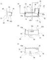
- FIG. 2 is a diagram showing the front cover 20 with the speaker box cover 40 attached to the back surface.
- 2A is a front view
- FIG. 2B is a rear view
- FIG. 2C is a bottom view
- FIG. 2D is a cross-sectional view taken along line X2-X2 of FIG. 2A.
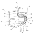
- FIG. 3 is a cross-sectional view of the front cover 20 with the speaker box cover 40 attached to the back surface, and is a cross-sectional view taken along the line X1-X1 of FIG.
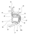
- FIG. 4 is a cross-sectional view of the front cover 20 with the speaker box cover 40 attached to the back surface, and is a cross-sectional view taken along the line X3-X3 of FIG.
- FIG. 5 is a view showing the front cover 20 with the rear speaker box cover 40 removed.
- 5 (a) is a front view
- FIG. 5 (b) is a rear view
- FIG. 5 (c) is a bottom view
- FIG. 5 (d) is a Y2-Y2 cross-sectional view of FIG. 5 (a).
- 5A to 5D correspond to FIGS. 2A to 2D described above.
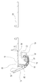
- FIG. 6 is a cross-sectional view of the front cover 20 with the speaker box cover 40 on the back surface removed, and is a cross-sectional view along Y1-Y1 in FIG. It is a figure of the state which removed the speaker box cover 40 from the state of FIG.
- FIG. 7 is a cross-sectional view of the front cover 20 with the rear speaker box cover 40 removed, and is a Y3-Y3 cross-sectional view of FIG. It is a figure of the state which removed the speaker box cover 40 from the state of FIG.
- two left and right speaker box covers 40 and a back cover 50 between them are arranged and attached to the back of the front cover 20.
- the front cover 20, the speaker box cover 40, and the back cover 50 are resin molded products.
- the first speaker body 47 and the second speaker body 48 are arranged inside the speaker box cover 40, more specifically, inside the space covered with the front cover 20 and the speaker box cover 40.
- the region where the first speaker main body 47 is arranged and the region where the second speaker main body 48 is arranged are formed as independent spaces. That is, in the region where the first speaker body 47 is arranged, the front cover 20 and the speaker box cover 40 form a first speaker box 45 (enclosure) of the speaker system. Similarly, in the region where the second speaker main body 48 is disposed, the front cover 20 and the speaker box cover 40 form a second speaker box 46.
- the IR unit 70 is arranged inside one first speaker box 45 (here, the first speaker box 45 on the left side of FIG. 2A or FIG. 2D). Specifically, a rib-shaped attachment arrangement portion 25 is formed in a predetermined region on the back surface of the cover main body 21. An attachment 60 to which the IR unit 70 is attached is fixed to the attachment placement unit 25. As a result, in the first speaker box 45 on the left side of the figure, the attachment placement unit 25 functions as a partial structure of the enclosure.
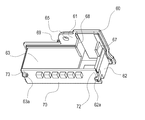
- FIG. 8 is a perspective view of the attachment 60 with the IR unit 70 attached thereto.
- FIG. 9 is a diagram showing the attachment 60 with the IR unit 70 attached thereto.
- 9 (a) is a front view
- FIG. 9 (b) is a bottom view
- FIG. 9 (c) is a Z1-Z1 sectional view of FIG. 9 (a)
- FIG. 9 (d) is Z2- It is Z2 sectional drawing.
- FIG. 10 shows the attachment 60 with the IR unit 70 removed.
- 10 (a) is a front view
- FIG. 10 (b) is a rear view
- FIG. 10 (c) is a plan view
- FIG. 10 (d) is a bottom view
- FIG. 10 (e) is a right side view
- FIG. ) Is a left side view
- FIG. 10G is a cross-sectional view taken along the line W1-W1 of FIG.
- FIG. 11 is an enlarged view showing a region where the substantially L-shaped attachment placement portion 25 in which the attachment 60 for the IR unit 70 is placed is formed.
- the attachment 60 is a resin molded product, and includes a plate-like attachment base portion 61, first and second fixing ribs 62, 63, and first and second rib structures extending vertically from the attachment base portion 61 to the front. Second guide walls 67 and 68 are provided.
- the attachment base portion 61 has a substantially L shape (inverted L shape in FIG. 9 and the like), and a fixing opening 65 is formed in the inner region of the bent portion.
- First and second fixing ribs 62 and 63 are vertically formed on the front surface side of the attachment base portion 61. More specifically, first fixing ribs 62 are formed in the vicinity of the right and lower outer edges of the region corresponding to the L-shaped laterally extending portion. Moreover, the 2nd fixing rib 63 is formed in the left side and upper part of the L-shaped part extended horizontally.
- the first and second fixing ribs 62 and 63 are formed at the same height, and the substrate surface of the IR unit 70 is disposed in contact with the tip portion thereof. Further, in order to fix the substrate of the IR unit 70, the first and second fixing ribs 62 and 63 are formed with claw-shaped locking portions 62a and 63a, respectively.
- the substrate of the IR unit 70 has locking recesses 72 and 73 for locking the locking portions 62a and 63a.
- a positioning piece 62b is formed on the first fixing rib.
- a first guide wall 67 is formed in the right region of the L-shaped vertically extending region, and a second guide wall 68 is formed in the left region.
- the first guide wall 67 is formed continuously with the first fixing rib 62, but is formed lower than the height of the first fixing rib 62.
- the second guide wall 68 is formed continuously with the second fixing rib 63, but is formed lower than the height of the second fixing rib 63.
- the first and second guide walls 67 and 68 have a line shaping structure for wiring, and guide the wiring of the IR unit 70 to the wiring opening 28 shown in FIGS. 4 and 7.
- the left portion of the first fixing rib 62 is formed to be separated from the second fixing rib 63 by a predetermined distance. That is, the first fixing rib 62 is not formed in the vicinity of the left end portion of the L-shaped side extending portion.
- a communication path from the upper right to the lower left of the attachment 60 is formed.
- the upper right portion of the communication path communicates with the wiring opening 28 described above.
- a box cover fixing boss 69 is formed on the back side of the attachment base 61, and screws (screws) are fastened to fix the speaker box cover 40.
- the sealed state of the first speaker box 45 is secured in a state where the attachment base portion 61 of the attachment 60 is attached to the attachment placement portion 25. That is, the IR unit 70 is disposed in the front portion of the attachment placement unit 25. Further, an IR opening 27 is formed on the front side, and an IR cover 75 is attached. Further, several openings are formed in the front cover 20 for wiring the IR unit 70. Therefore, if sealing such as the absence of the attachment base 61 is not taken into consideration, the function of the first speaker box 45 as an enclosure becomes inappropriate. However, in this embodiment, the sealed state of the first speaker box 45 can be ensured.
- an infrared transmitting / receiving element is arranged on a substrate on which a predetermined circuit is formed. Since the IR unit 70 is disposed at the tip portions of the first and second fixing ribs 62 and 63, the infrared transmitting / receiving element of the IR unit 70 can be positioned to the immediate vicinity of the IR cover 75.
- the IR unit 70 When the IR unit 70 is disposed at the left and right ends of the liquid crystal television 10 as in the present embodiment instead of the center in the left-right direction, it is brought close to the surface of the front cover 20 from the viewpoint of communication characteristics such as directivity. Is preferred. Also in this respect, the present embodiment can achieve good performance. Further, even when the shape of the IR unit 70 is changed due to the change of the infrared transmitting / receiving element or the like, it is possible to cope to some extent by changing only the first and second fixing ribs 62 and 63. Therefore, the design change of the front cover 20 can be avoided, and only the design change of the attachment 60, that is, the small part design change can be dealt with.
- the IR unit 70 is arranged in the attachment arrangement portion 25 using an attachment 60 that functions as a seal cover (SEAL cover).
- SEAL cover a seal cover
- the volume in the speaker box is a factor that determines the characteristics of the speaker box (the first and second speaker boxes 45 and 46). Since the frequency characteristics and output of the speaker change depending on the movement of air in the speaker box, the left and right speaker characteristics need to be the same as much as possible in the stereo speaker.
- the IR unit 70 that is a wireless communication unit is arranged in the speaker box, it is necessary to consider that the volume and the internal shape of the speaker box are not different from each other depending on the installation of the wireless communication unit. That is, it is necessary to make the speaker box have the same volume and the same internal shape regardless of whether or not the IR unit 70 is arranged.
- the shape of the ends of both the left and right speakers (here, both the left and right)
- the internal shape of the first speaker box 45 is the same.
- the volume and internal shape of the left and right speaker boxes are the same, and the sound quality of the speakers can be maintained appropriately.
- the shape of the front cover 20 on the side where the IR unit 70 is not disposed is formed in accordance with the structure on the side where the IR unit 70 is disposed, that is, the structure of the attachment 60 (attachment base portion 61). May be.
- the same structure as that on the side where the IR unit 70 is arranged may be adopted on the side where the IR unit 70 is not arranged.
- the back structure (speaker box portion) of the front cover 20 is the same on the left and right, and one has the attachment 60 with the IR unit 70 attached, and the other has only the attachment 60 without the IR unit 70 attached. Also good.
- the attachment 60 to which the IR unit 70 is attached can be arranged up to a desired position, that is, the front cover 20 (the IR cover 75) just by placing and fixing the attachment 60 to the attachment placement unit 25. The workability is improved.
- the IR unit 70 is disposed on the attachment 60, so-called chattering (vibration / noise) due to substrate resonance during sound output can be avoided.
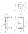
- FIG. 12A and 12B are three views of the attachment 160 according to this embodiment.
- FIG. 12A is a front view
- FIG. 12B is a bottom view
- FIG. 12C is a side view.
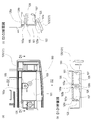
- 13A and 13B are diagrams showing a state in which the attachment 160 is attached to the attachment placement portion 125.
- FIG. 13A is a plan view
- FIG. 13B is a cross-sectional view taken along line D1-D1 of FIG. 13 (c) is a sectional view taken along the line D2-D2 of FIG. 13 (a).
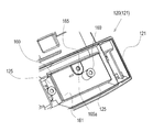
- FIG. 14 is a perspective view showing a state in which the attachment 160 is attached to the attachment placement portion 125, and corresponds to FIG. 13 (a).
- the description of the configuration and function similar to those of the first embodiment will be omitted as appropriate, and the description will be focused on the fixing structure between the attachment 160 and the cover main body 121 that is characteristic of the present embodiment. .
- a rib-shaped attachment arrangement portion 125 is formed in a predetermined area on the back surface of the cover main body 121 of the front cover 120 so as to surround the predetermined area in a frame shape.
- the attachment 160 is fixed to the attachment placement unit 125.
- a region surrounded by the attachment placement portion 125 is referred to as a cover-side enclosure surface 129 for convenience.
- the attachment 160 is a resin molded product, and includes a rectangular plate-shaped attachment base portion 161, a plate-shaped guide wall 167 that extends vertically forward from the attachment base portion 161, and the first and first attachments.
- Two fixing ribs 162 and 163 are provided.
- the guide wall 167 is formed in a substantially U shape in a bottom view at a position slightly inside the outer edge of the rectangular attachment base surface 161.
- the U-shape is inverted, and the guide wall 167 is not formed on the upper side portion.
- the region from the outer edge to the guide wall 167 and the region of the upper side corresponding to the region are the outer edge arrangement surface 161a.
- the IR unit 70 (not shown) is attached to the locking portions 162a and 163a at the tips of the first and second fixing ribs 162 and 163 as in the first embodiment.
- a box cover fixing boss 169 extending upward (in the direction of the back surface of the liquid crystal television 10) is provided at substantially the center of the attachment base surface 161.
- a boss mounting portion 165 is provided near the box cover fixing boss 169. The boss mounting portion 165 is used for fixing to the attachment base surface 161 with a screw (not shown).
- the boss mounting portion 165 has a fixing opening that penetrates the attachment base surface 161 in the vicinity of the center of the shape slightly convex on the upper surface side of the attachment base surface 161 (the side opposite to the cover main body 121). 165a is formed.
- a circular concave-shaped boss tip contact portion 165b is formed on the bottom surface side of the attachment base surface 161 so as to surround the periphery of the fixing opening 165a.
- a substantially cylindrical attachment fixing boss 126 is provided to extend from the cover side enclosure surface 129 at a position corresponding to the boss mounting portion 165 inside the attachment placement portion 125.
- the boss leading end portion 126 a that is the leading end surface of the attachment fixing boss 126 faces the attachment placement portion 125.
- a fixing opening 126b used for screw fixing is formed in the boss tip 126a.
- the boss tip portion 126a and the boss tip contact portion 165b come into contact with each other.
- the attachment base surface 161 is relatively close to the direction of the cover main body 121 and the attachment base surface 161 is pulled, so that the attachment base surface 161 and the attachment placement portion 125 have good sealing performance. Maintained. As a result, no sealing material is required for sealing the attachment base surface 161 and the attachment placement portion 125. Further, since the boss mounting portion 165 and the box cover fixing boss 169 are formed on the attachment base surface 161, the work of mounting the attachment 160 to the cover body 121 is reduced.
- the guide wall 167 is formed on three sides (left and right sides and lower side) of the attachment base surface 161.
- the adhesion between the guide wall 167 and the attachment placement portion 125 contributes to the sealing performance.
- the guide wall 167 is not formed on the upper side. Therefore, in this region, it is necessary to ensure good sealing performance only by joining the outer edge arrangement surface 161a and the arrangement portion front end surface 125a. From this point of view, the boss mounting portion 165 is formed not on the center of the attachment base surface 161 but on the upper side.
- the guide wall 167 may be omitted, and in that case, the boss mounting portion 165 is preferably located at the center of the attachment base surface 161. Further, from the viewpoint of improving the sealing performance, a slight build-up shape (such as a convex shape) may be formed on the outer portion of the guide wall 167 and at a certain distance from the attachment base surface 161.
- the IR unit 70 is exemplified as the wireless communication unit, but the present invention can also be applied to other types of wireless communication units such as a wireless LAN and Bluetooth (registered trademark).
- an adhesive rubber material may be provided at the attachment portion of various structural members.
- this embodiment is applied to the front cover from which the lower part of the front cabinet is separated, it is naturally applicable to a type of cabinet in which the front cover is not separated.
Landscapes
- Engineering & Computer Science (AREA)
- Multimedia (AREA)
- Signal Processing (AREA)
- Details Of Audible-Bandwidth Transducers (AREA)
Abstract
スピーカーを備える薄型表示装置において、スピーカーが配置されるスペースを利用して無線通信ユニットを取り付けることができる技術を提供する。 一方の第1のスピーカーボックス45の内部にはIRユニット70が配置される。具体的には、カバー本体21の裏面の所定の領域にリブ状のアタッチメント配置部25が形成されている。アタッチメント配置部25にIRユニット70が取り付けられたアタッチメント60が固定される。アタッチメント60は、アタッチメントベース部61から延出する第1及び第2の固定用リブ62の先端にIRユニット70を取り付けている。その結果、IRユニット70の送受信素子は、IR用カバー75の近傍ぎりぎりに配置されている。
Description
本発明は、薄型表示装置において無線通信ユニットを固定する技術に関する。
液晶テレビに代表される薄型表示装置において、リモコン通信等の無線通信に用いられる無線通信ユニットは、表示装置本体正面のフロントキャビ下部の樹脂製の額縁内に配置されることが多い。
しかしながら、近年、表示装置の薄型化・軽量化・狭額縁化の進展が一層進む状況にある。そのような状況にあっては、無線通信ユニットが従来配置されていた空間が狭くなり、取り付けスペースの確保が困難になってきていた。また、近年では、リモコン通信の他に3D映像用の同期信号の送受信や無線LAN、ブルートゥース通信(登録商標)が行われるようになっており、それらの無線通信ユニットの配置スペースの確保が重要になってきている。
無線通信ユニット等の配置に関して、スペースの有効活用の観点で各種の技術が提案されている。例えば、信号源の光ビームを受光する受光装置をスピーカーボックスに内蔵し、その指向性を広げることを目的として技術がある(例えば、特許文献1参照)。より具体的には、L型に形成した操作レバーの一端につまみと、他端に長孔を設け、固定シャーシの前面板に回動自在に軸支する。一方、受光ユニットを取付けた回転シャーシが設けられる。回転シャーシは回転軸を介し固定シャーシの前面板に回動自在に保持する。つまみを左右に回すと、長孔に係合した駆動片が傾き、回転シャーシが上下に回動する。このような構成によって、受光ユニットの光軸は上方又は下方に傾斜し、光ビームの受光範囲を任意に設定することができる。
ところで、上述のような狭額縁化に加え、筐体(特にフロントキャビネット)のデザインの制約の観点から、赤外線等の無線通信ユニットを本体前面に専用スペースを確保して配置することが困難になるケースがあった。
特許文献1に開示の技術では、スピーカーボックス内に、受光部を配置しているが、この技術をそのまま適用することは、密閉性の確保や製造時の作用性等の観点から、また近年のように狭額縁化や薄型化の進展が著しい状況においては、現実的ではなく別の技術が必要とされていた。
本発明は以上のような状況に鑑みなされたものであって、上記課題を解決する技術を提供することを目的とする。
本発明の薄型表示装置は、表示部の外縁のキャビネットと、前記キャビネットの背面を覆うように配置されるスピーカーボックスと、前記キャビネットと前記スピーカーボックスとに囲まれる領域の内部に配置される無線通信ユニットと、前記無線通信ユニットを固定するためのアタッチメントと、を有し、前記アタッチメントが、前記スピーカーボックス及び前記キャビネットを備えて構成するエンクロージャーの一部の構成となって、前記エンクロージャーの密閉を確保している。
また、前記アタッチメントは、前記キャビネットに固定されるアタッチメントベース部と、前記アタッチメントベース部から延出し端部に前記無線通信ユニットを固定する固定用リブとを有してもよい。
本発明の薄型表示装置は、表示部の外縁のキャビネットと、前記キャビネットの背面を覆うように配置されるスピーカーボックスと、前記キャビネットと前記スピーカーボックスとに囲まれる領域の内部に配置される無線通信ユニットと、前記スピーカーボックス及び前記キャビネットを備えて構成するエンクロージャーの一部の構成となるアタッチメントと、を有し、前記キャビネットは、前記エンクロージャーの一部を構成するとともに、その先端部に前記アタッチメントが配置される壁面状で所定領域を囲むように形成されたアタッチメント配置部と、前記アタッチメント配置部が囲む領域から延出したボスとを有し、前記アタッチメントは、前記ボスの先端を当接させて配置させるとともに、前記アタッチメント配置部とネジ止めされる固定部を有し、前記アタッチメントと前記配置部がネジ固定される前の状態では、前記ボスの先端と前記固定部とは離間している。
前記アタッチメントは、前記キャビネットに固定されるアタッチメントベース部と、前記アタッチメントベース部から延出し端部にリブとを有し、前記リブにより前記無線通信ユニットが固定されてもよい。
また、前記アタッチメントは、前記キャビネットに固定されるアタッチメントベース部と、前記アタッチメントベース部から延出し端部に前記無線通信ユニットを固定する固定用リブとを有してもよい。
本発明の薄型表示装置は、表示部の外縁のキャビネットと、前記キャビネットの背面を覆うように配置されるスピーカーボックスと、前記キャビネットと前記スピーカーボックスとに囲まれる領域の内部に配置される無線通信ユニットと、前記スピーカーボックス及び前記キャビネットを備えて構成するエンクロージャーの一部の構成となるアタッチメントと、を有し、前記キャビネットは、前記エンクロージャーの一部を構成するとともに、その先端部に前記アタッチメントが配置される壁面状で所定領域を囲むように形成されたアタッチメント配置部と、前記アタッチメント配置部が囲む領域から延出したボスとを有し、前記アタッチメントは、前記ボスの先端を当接させて配置させるとともに、前記アタッチメント配置部とネジ止めされる固定部を有し、前記アタッチメントと前記配置部がネジ固定される前の状態では、前記ボスの先端と前記固定部とは離間している。
前記アタッチメントは、前記キャビネットに固定されるアタッチメントベース部と、前記アタッチメントベース部から延出し端部にリブとを有し、前記リブにより前記無線通信ユニットが固定されてもよい。
本発明によれば、スピーカーを備える薄型表示装置において、スピーカーが配置されるスペースを利用して無線通信ユニットを取り付けることができる技術を提供することができる。
次に、本発明を実施するための形態(以下、単に「実施形態」という)を、図面を参照して具体的に説明する。
<第1の実施形態>
図1は液晶テレビ10を示す図である。図示のように、液晶テレビ10は、表示パネル12の下側領域にフロントカバー20を備えている。また、フロントカバー20は、カバー本体21とカバー取付部22とを備える。
図1は液晶テレビ10を示す図である。図示のように、液晶テレビ10は、表示パネル12の下側領域にフロントカバー20を備えている。また、フロントカバー20は、カバー本体21とカバー取付部22とを備える。
カバー本体21にはスピーカーカバー30及びトリム33が配置されている。スピーカーカバー30の内部には後述するスピーカーユニットが配置される。また、スピーカーカバー30の図示で左側端部近傍(領域A)には、IR用カバー75が取り付けられ、その背面内部側には後述するIRユニット70(図2等を参照)が配置される。IRユニット70は、リモコンや3Dメガネ等との赤外線通信に用いられる。なお、本実施形態では、薄型表示装置として液晶テレビ10について例示するが、他に有機ELテレビ等についても適用可能である。
図2は背面にスピーカーボックスカバー40が取り付けられた状態のフロントカバー20を示す図である。図2(a)は正面図、図2(b)は背面図、図2(c)は底面図、図2(d)は図2(a)のX2-X2断面図である。
図3は背面にスピーカーボックスカバー40が取り付けられた状態のフロントカバー20の断面図であって、図2(a)のX1-X1断面図である。図4は背面にスピーカーボックスカバー40が取り付けられた状態のフロントカバー20の断面図であって、図2(b)のX3-X3断面図である。
図5は背面のスピーカーボックスカバー40が取り外された状態のフロントカバー20を示す図である。図5(a)は正面図、図5(b)は背面図、図5(c)は底面図、図5(d)は図5(a)のY2-Y2断面図である。なお、図5(a)~(d)は、上述の図2(a)~(d)に対応する。
図6は背面のスピーカーボックスカバー40が取り外された状態のフロントカバー20の断面図であって、図5(a)のY1-Y1断面図である。図3の状態からスピーカーボックスカバー40を取り外した状態の図である。図7は背面のスピーカーボックスカバー40が取り外された状態のフロントカバー20の断面図であって、図5(a)のY3-Y3断面図である。図4の状態からスピーカーボックスカバー40を取り外した状態の図である。
例えば図2に示すように、フロントカバー20の背面には左右の2つのスピーカーボックスカバー40と、それらの間の背面カバー50とが配置され取り付けられている。フロントカバー20、スピーカーボックスカバー40及び背面カバー50は樹脂成形品である。
スピーカーボックスカバー40の内部、より詳細にはフロントカバー20とスピーカーボックスカバー40で覆われた空間の内部に第1のスピーカー本体47及び第2のスピーカー本体48が配置されている。
第1のスピーカー本体47が配置される領域と、第2のスピーカー本体48が配置される領域は独立した空間として形成されている。つまり、第1のスピーカー本体47が配置される領域は、フロントカバー20及びスピーカーボックスカバー40によってスピーカシステムの第1のスピーカーボックス45(エンクロージャー)を形成している。同様に、第2のスピーカー本体48が配置される領域は、フロントカバー20とスピーカーボックスカバー40によって第2のスピーカーボックス46を形成している。
一方の第1のスピーカーボックス45(ここでは図2(a)または図2(d)の図示左側の第1のスピーカーボックス45)の内部にはIRユニット70が配置される。具体的には、カバー本体21の裏面の所定の領域にリブ状のアタッチメント配置部25が形成されている。アタッチメント配置部25に、IRユニット70が取り付けられたアタッチメント60が固定される。その結果、図示左側の第1のスピーカーボックス45では、アタッチメント配置部25がエンクロージャーの一部構造として機能する。
図8はIRユニット70が取り付けられた状態のアタッチメント60の斜視図である。
図9はIRユニット70が取り付けられた状態のアタッチメント60を示す図である。図9(a)は正面図、図9(b)は底面図、図9(c)は図9(a)のZ1-Z1断面図、図9(d)は図9(a)のZ2-Z2断面図である。
図10はIRユニット70が取り外された状態のアタッチメント60を示す図である。図10(a)は正面図、図10(b)は背面図、図10(c)は平面図、図10(d)は底面図、図10(e)は右側面図、図10(f)は左側面図、図10(g)は図10(a)のW1-W1断面図である。
図11はIRユニット70用のアタッチメント60が配置される略L字形状のアタッチメント配置部25が形成される領域を拡大して示す図である。
アタッチメント60は樹脂成形品であって、板状のアタッチメントベース部61と、アタッチメントベース部61から前方に垂直に延出するリブ構造の第1及び第2の固定用リブ62、63及び第1及び第2のガイド壁67、68を有している。
より具体的には、アタッチメントベース部61は略L字形状(図9等では逆L字形状)であって、屈曲部分の内側領域には固定用開口65が形成されている。アタッチメントベース部61の前面側には垂直に第1及び第2の固定用リブ62、63が延出して形成されている。より具体的には、L字形状の横に延びる部分に対応する領域の右側及び下側の外縁付近に第1の固定用リブ62が形成されている。また、L字形状の横に延びる部分の左側及び上側部分に第2の固定用リブ63が形成されている。
第1及び第2の固定用リブ62、63は同じ高さに形成されており、その先端部分にIRユニット70の基板面が当接して配置される。また、IRユニット70の基板を固定するために、第1及び第2の固定用リブ62、63にはそれぞれツメ状の係止部62a、63aが形成されている。なお、IRユニット70の基板には、係止部62a、63aが係止するための係止凹部72、73が形成されている。また、第1の固定用リブには位置決め片62bが形成されている。
また、L字形状の縦に延びる領域の右側の領域に第1のガイド壁67が形成され、左側の領域に第2のガイド壁68が形成されている。第1のガイド壁67は、第1の固定用リブ62と連続して形成されているが、第1の固定用リブ62の高さより低く形成されている。同様に、第2のガイド壁68は、第2の固定用リブ63と連続して形成されているが第2の固定用リブ63の高さより低く形成されている。第1及び第2のガイド壁67、68は、配線用の線整形の構造であって、IRユニット70の配線を図4や図7に示す配線用開口28にガイドする。
また、第1の固定用リブ62の左側部分は、第2の固定用リブ63と所定距離分離するように形成されている。つまり、L字形状の横に延びる部分の左側端部近傍には第1の固定用リブ62が形成されていない。
したがって、IRユニット70が第1及び第2の固定用リブ62、63に配置された状態で、アタッチメント60の右上から左下に向かう連通経路が形成される。連通経路の右上部分は上述の配線用開口28に連絡する。
また、アタッチメントベース部61の裏面側にはボックスカバー固定用ボス69が形成されており、スピーカーボックスカバー40の固定の為にネジ(ビス)が締結される。
アタッチメント60のアタッチメントベース部61がアタッチメント配置部25に取り付けられた状態で、第1のスピーカーボックス45の密閉状態が確保されている。つまり、アタッチメント配置部25の前方部分には、IRユニット70が配置される。そして、さらにその前方には、IR用開口27が形成されIR用カバー75が取り付けられる。また、フロントカバー20にはIRユニット70の配線を行うためにいくつかの開口が形成される。したがって、アタッチメントベース部61が無い等の密閉を考慮されていないと、第1のスピーカーボックス45のエンクロージャーとしての機能が不適切となってしまう。しかし、本実施形態では、第1のスピーカーボックス45の密閉状態が確保できる。
また、IRユニット70には、所定の回路が形成された基板上に赤外線送受信素子が配置されている。第1及び第2の固定用リブ62、63の先端部分にIRユニット70が配置されるので、IR用カバー75のすぐ近くまでIRユニット70の赤外線送受信素子を位置させることができる。
本実施形態の様に、IRユニット70が液晶テレビ10の左右方向中央ではなく左右の端部に配置される場合には、指向性等の通信特性の観点からフロントカバー20の表面ぎりぎりまで近づけることが好ましい。この点でも、本実施形態では良好な性能を実現できる。また、赤外線送受信素子等の変更によってIRユニット70の高さ等の形状に変化があった場合でも、第1及び第2の固定用リブ62、63のみの変更である程度対応可能である。そのため、フロントカバー20の設計変更を避け、アタッチメント60のみの設計変更、つまり、小さな部品設計変更のみで対応可能である。
また、第1のスピーカーボックス45において、アタッチメント配置部25にシールカバー(SEALカバー)として機能するアタッチメント60を用いてIRユニット70を配置している。その結果、スピーカーユニットの性能を所望に確保することができる。つまり、アタッチメント60のアタッチメントベース部61が第1のスピーカーボックス45のエンクロージャーの一部としての構造となることで、IRユニット70の配置構造にともない開口が形成され密閉性が低下してしまうことから回避している。
なお、スピーカーボックス(第1及び第2のスピーカーボックス45、46)の特性を決める要素として、スピーカーボックス内の容積がある。スピーカーの周波数特性及び出力は、スピーカーボックス内の空気の動きによって変化するので、ステレオスピーカーにおいては、左右のスピーカー特性は極力同一にする必要がある。スピーカーボックス内に無線通信ユニットであるIRユニット70を配置する際、無線通信ユニットの設置によって、スピーカーボックスの容積や内部形状が左右で相違しないよう配慮する必要がある。つまり、IRユニット70の配置の有無に拘わらず、スピーカーボックスの容積や内部形状が同一であるようにする必要がある。そこで本実施形態では、一方のスピーカーの端部に上述のようにIRユニット70を配置して、アタッチメント60(シールカバー)を取り付けた後は、左右両方のスピーカーの端部形状(ここでは左右両方の第1のスピーカーボックス45の内部形状)が同一となる構造を採用している。その結果、左右のスピーカーボックスの容積や内部形状が同一となり、スピーカーの音質品位を適正に保つことができる。同一構造とするために、IRユニット70が配置されない側のフロントカバー20の形状が、IRユニット70が配置される側の構造、つまりアタッチメント60(アタッチメントベース部61)の構造に一致されて成形されてもよい。また、IRユニット70が配置されない側にも、IRユニット70が配置される側と同様の構造が採用されてもよい。つまり、フロントカバー20の背面構造(スピーカーボックス部分)は左右同一として、一方はIRユニット70を取り付けたアタッチメント60が配置され、他方にはIRユニット70を取り付けないアタッチメント60のみが配置される構造としてもよい。
また、IRユニット70をフロントカバー20表面ぎりぎりまで配置させる場合、従来の一般的な技術であれば、治具等を用いて慎重に作業する必要があった。しかし、本実施形態では、IRユニット70が取り付けられたアタッチメント60をアタッチメント配置部25に配置・固定するだけで、所望の位置、つまりフロントカバー20(IR用カバー75)ぎりぎりまで配置させることができ、作業性の向上が図られる。
さらに、アタッチメント60にIRユニット70が配置されるので、音声出力時の基板共振によるいわゆるビビリ(振動・騒音)を回避できる。
<第2の実施形態>
図12は本実施形態に係るアタッチメント160の三面図であり、図12(a)は正面図、図12(b)は底面図、図12(c)は側面図である。図13は、アタッチメント160がアタッチメント配置部125に取り付けられた状態を示す図であり、図13(a)は平面図、図13(b)は図13(a)のD1-D1断面図、図13(c)は図13(a)のD2-D2断面図である。また、図14はアタッチメント160がアタッチメント配置部125に取り付けられた状態の斜視図であり、図13(a)に対応する図である。なお、以下の説明では、第1の実施形態と同様の構成・機能については適宜説明を省略し、おもに本実施形態に特徴的なアタッチメント160とカバー本体121との固定構造に着目して説明する。
図12は本実施形態に係るアタッチメント160の三面図であり、図12(a)は正面図、図12(b)は底面図、図12(c)は側面図である。図13は、アタッチメント160がアタッチメント配置部125に取り付けられた状態を示す図であり、図13(a)は平面図、図13(b)は図13(a)のD1-D1断面図、図13(c)は図13(a)のD2-D2断面図である。また、図14はアタッチメント160がアタッチメント配置部125に取り付けられた状態の斜視図であり、図13(a)に対応する図である。なお、以下の説明では、第1の実施形態と同様の構成・機能については適宜説明を省略し、おもに本実施形態に特徴的なアタッチメント160とカバー本体121との固定構造に着目して説明する。
第1の実施形態と同様に、フロントカバー120のカバー本体121裏面の所定の領域にリブ状のアタッチメント配置部125が枠状に所定領域を囲むようにして形成されている。アタッチメント配置部125に、アタッチメント160が固定される。なお、カバー本体121において、アタッチメント配置部125に囲まれる領域を便宜的にカバー側エンクロージャー面129と言う。
具体的には、アタッチメント160は、樹脂成形品であって、長方形の板状のアタッチメントベース部161と、アタッチメントベース部161から前方に垂直に延出する板状のガイド壁167及び第1及び第2の固定用リブ162、163を有している。
ガイド壁167は、長方形のアタッチメントベース面161の外縁より若干内側位置に底面視で略コ字状に形成されている。ここではコ字を倒した形状であり、上辺部分にガイド壁167が形成されていない。なお、アタッチメントベース面161の左右及び下辺において、その外縁からガイド壁167までの領域及びその領域に対応する上辺部分の領域が外縁配置面161aとなっている。そして、アタッチメントベース面161がアタッチメント配置部125に取り付けられるときに、外縁配置面161aにアタッチメント配置部125の先端の平面である配置部先端面125aが当接する。
第1及び第2の固定用リブ162、163の先端の係止部162a、163aには、第1の実施形態と同様にIRユニット70(図示せず)が取り付けられる。
アタッチメントベース面161の略中央には、上方向(液晶テレビ10の背面方向)に延出するボックスカバー固定用ボス169が設けられている。また、ボックスカバー固定用ボス169の近くにはボス取付部165が設けられている。ボス取付部165はアタッチメントベース面161へのネジ(図示せず)による固定に用いられる。
具体的には、ボス取付部165は、アタッチメントベース面161の上面側(カバー本体121とは反対側)に若干凸状になった形状の中央付近に、アタッチメントベース面161を貫通する固定用開口165aが形成されている。
アタッチメントベース面161の底面側には、固定用開口165aの周囲を囲むように円形凹状形状のボス先端当接部165bが形成されている。
一方、カバー本体121において、アタッチメント配置部125内側のボス取付部165に対応する位置には、略筒状のアタッチメント固定ボス126がカバー側エンクロージャー面129から延出して設けられている。カバー本体121にアタッチメント160が取り付けられた状態で、アタッチメント固定ボス126の先端面であるボス先端部126aがアタッチメント配置部125に対向するようになっている。また、ボス先端部126aには、ネジ固定に用いられる固定用開口126bが形成されている。
ネジ留めされていない状態では、図13(b)や図13(c)のように、アタッチメント固定ボス126のボス先端部126aとボス取付部165のボス先端当接部165bとは、僅かに離間している。このとき、外縁配置面161aと配置部先端面125aとは当接した状態にある。
そして、固定用開口165a、126bとでネジ留めがされると、ボス先端部126aとボス先端当接部165bとが当接する。このとき、離間している分だけアタッチメントベース面161がカバー本体121の方向に相対的に近づき、アタッチメントベース面161が引っ張られることで、アタッチメントベース面161とアタッチメント配置部125の密封性が良好に維持される。その結果、アタッチメントベース面161とアタッチメント配置部125の密封にシール材が不要になる。また、ボス取付部165やボックスカバー固定用ボス169がアタッチメントベース面161に形成されているので、アタッチメント160のカバー本体121への取付作業が軽減される。
なお、本実施形態では、アタッチメント160において、ガイド壁167がアタッチメントベース面161の三辺(左右及び下辺)に形成されている。このガイド壁167とアタッチメント配置部125との密着が、上記密封性に貢献する。一方、上辺にはガイド壁167が形成されていない。したがって、この領域では、外縁配置面161aと配置部先端面125aとの接合のみで密封性を良好に確保する必要がある。その観点から、ボス取付部165は、アタッチメントベース面161の中心ではなく、上辺側にずらして形成されている。
なお、ガイド壁167は省いても良く、その場合は、ボス取付部165はアタッチメントベース面161の中心にあることが望ましい。また、密閉性が向上の観点から、ガイド壁167の外側部分であってアタッチメントベース面161から一定距離部分に、僅かな肉盛り形状(凸形状等)が形成されてもよい。
以上、本発明を実施形態をもとに説明した。この実施形態は例示であり、それらの各構成要素の組み合わせ等にいろいろな変形例が可能なこと、またそうした変形例も本発明の範囲にあることは当業者に理解されるところである。
例えば、本実施形態では無線通信ユニットとしてIRユニット70を例示したが、無線LANやブルートゥース(登録商標)等の他のタイプの無線通信ユニットにも適用することができる。また、第1のスピーカーボックス45等の密閉性確保の観点から、各種構造部材の取り付け部分に粘着性ゴム材が設けられてもよい。また、本実施形態は、フロントキャビネットの下側部分が分離したフロントカバーに適用しているが、当然にフロントカバーが分離していないタイプのキャビネットにも適用可能である。
10 液晶テレビ
12 表示パネル
20、120 フロントカバー(キャビネット)
21、121 カバー本体
22 カバー取付部
25、125 アタッチメント配置部
27 IR用開口
28 配線用開口
30 スピーカーカバー
33 トリム
40 スピーカーボックスカバー
45 第1のスピーカーボックス
46 第2のスピーカーボックス
47 第1のスピーカー本体
48 第2のスピーカー本体
50 背面カバー
60、160 アタッチメント
61、161 アタッチメントベース部
62、162 第1の固定用リブ
62a、63a、162a、163a 係止部
62b 位置決め片
63、163 第2の固定用リブ
65 固定用開口
67 第1のガイド壁
68 第2のガイド壁
69、169 ボックスカバー固定用ボス
70 IRユニット
72、73 係止凹部
75 IR用カバー
125a 配置部先端面
126 アタッチメント固定ボス
126a ボス先端部
126b 固定用開口
129 カバー側エンクロージャー面
161a 外縁配置面
165 ボス取付部
165a 固定用開口
165b ボス先端当接部
167 ガイド壁
12 表示パネル
20、120 フロントカバー(キャビネット)
21、121 カバー本体
22 カバー取付部
25、125 アタッチメント配置部
27 IR用開口
28 配線用開口
30 スピーカーカバー
33 トリム
40 スピーカーボックスカバー
45 第1のスピーカーボックス
46 第2のスピーカーボックス
47 第1のスピーカー本体
48 第2のスピーカー本体
50 背面カバー
60、160 アタッチメント
61、161 アタッチメントベース部
62、162 第1の固定用リブ
62a、63a、162a、163a 係止部
62b 位置決め片
63、163 第2の固定用リブ
65 固定用開口
67 第1のガイド壁
68 第2のガイド壁
69、169 ボックスカバー固定用ボス
70 IRユニット
72、73 係止凹部
75 IR用カバー
125a 配置部先端面
126 アタッチメント固定ボス
126a ボス先端部
126b 固定用開口
129 カバー側エンクロージャー面
161a 外縁配置面
165 ボス取付部
165a 固定用開口
165b ボス先端当接部
167 ガイド壁
Claims (4)
- 表示部の外縁のキャビネットと、
前記キャビネットの背面を覆うように配置されるスピーカーボックスと、
前記キャビネットと前記スピーカーボックスとに囲まれる領域の内部に配置される無線通信ユニットと、
前記無線通信ユニットを固定するためのアタッチメントと、
を有し、
前記アタッチメントが、前記スピーカーボックス及び前記キャビネットを備えて構成するエンクロージャーの一部の構成となって、前記エンクロージャーの密閉を確保している
ことを特徴とする薄型表示装置。 - 前記アタッチメントは、前記キャビネットに固定されるアタッチメントベース部と、前記アタッチメントベース部から延出し端部に前記無線通信ユニットを固定する固定用リブとを有することを特徴とする請求項1に記載の薄型表示装置。
- 表示部の外縁のキャビネットと、
前記キャビネットの背面を覆うように配置されるスピーカーボックスと、
前記キャビネットと前記スピーカーボックスとに囲まれる領域の内部に配置される無線通信ユニットと、
前記スピーカーボックス及び前記キャビネットを備えて構成するエンクロージャーの一部の構成となるアタッチメントと、
を有し、
前記キャビネットは、前記エンクロージャーの一部を構成するとともに、その先端部に前記アタッチメントが配置される壁面状で所定領域を囲むように形成されたアタッチメント配置部と、前記アタッチメント配置部が囲む領域から延出したボスとを有し、
前記アタッチメントは、前記ボスの先端を当接させて配置させるとともに、前記アタッチメント配置部とネジ止めされる固定部を有し、
前記アタッチメントと前記配置部がネジ固定される前の状態では、前記ボスの先端と前記固定部とは離間している
ことを特徴とする薄型表示装置。 - 前記アタッチメントは、前記キャビネットに固定されるアタッチメントベース部と、前記アタッチメントベース部から延出し端部にリブとを有し、
前記リブにより前記無線通信ユニットが固定されている
ことを特徴とする請求項3に記載の薄型表示装置。
Applications Claiming Priority (4)
| Application Number | Priority Date | Filing Date | Title |
|---|---|---|---|
| JP2013-113963 | 2013-05-30 | ||
| JP2013113963A JP5650279B2 (ja) | 2013-05-30 | 2013-05-30 | 薄型表示装置 |
| JP2013-230109 | 2013-11-06 | ||
| JP2013230109A JP5650307B1 (ja) | 2013-11-06 | 2013-11-06 | 薄型表示装置 |
Publications (1)
| Publication Number | Publication Date |
|---|---|
| WO2014192843A1 true WO2014192843A1 (ja) | 2014-12-04 |
Family
ID=51988866
Family Applications (1)
| Application Number | Title | Priority Date | Filing Date |
|---|---|---|---|
| PCT/JP2014/064207 Ceased WO2014192843A1 (ja) | 2013-05-30 | 2014-05-29 | 薄型表示装置 |
Country Status (1)
| Country | Link |
|---|---|
| WO (1) | WO2014192843A1 (ja) |
Citations (5)
| Publication number | Priority date | Publication date | Assignee | Title |
|---|---|---|---|---|
| JPH0787424A (ja) * | 1993-09-10 | 1995-03-31 | Sony Corp | 映像機器 |
| JP2004022663A (ja) * | 2002-06-13 | 2004-01-22 | Sanyo Electric Co Ltd | 受光装置 |
| JP2006345294A (ja) * | 2005-06-09 | 2006-12-21 | Toshiba Corp | 映像表示装置 |
| JP2007329829A (ja) * | 2006-06-09 | 2007-12-20 | Canon Inc | 薄型ディスプレイ装置 |
| JP2009159084A (ja) * | 2007-12-25 | 2009-07-16 | Orion Denki Kk | 表示装置 |
-
2014
- 2014-05-29 WO PCT/JP2014/064207 patent/WO2014192843A1/ja not_active Ceased
Patent Citations (5)
| Publication number | Priority date | Publication date | Assignee | Title |
|---|---|---|---|---|
| JPH0787424A (ja) * | 1993-09-10 | 1995-03-31 | Sony Corp | 映像機器 |
| JP2004022663A (ja) * | 2002-06-13 | 2004-01-22 | Sanyo Electric Co Ltd | 受光装置 |
| JP2006345294A (ja) * | 2005-06-09 | 2006-12-21 | Toshiba Corp | 映像表示装置 |
| JP2007329829A (ja) * | 2006-06-09 | 2007-12-20 | Canon Inc | 薄型ディスプレイ装置 |
| JP2009159084A (ja) * | 2007-12-25 | 2009-07-16 | Orion Denki Kk | 表示装置 |
Similar Documents
| Publication | Publication Date | Title |
|---|---|---|
| US9844153B2 (en) | Display device | |
| JP5496542B2 (ja) | 画像表示装置 | |
| JP7104104B2 (ja) | 表示装置 | |
| JP7552590B2 (ja) | スピーカ装置、スピーカ、及び構造体 | |
| US20200166966A1 (en) | Display apparatus | |
| JP2011182035A (ja) | テレビジョン受像機 | |
| JP2012004983A (ja) | 電子機器 | |
| EP3908008B1 (en) | Display device and speaker | |
| JP2011160319A (ja) | 音響装置、表示装置 | |
| KR101000015B1 (ko) | 스피커 구조 | |
| JP5650307B1 (ja) | 薄型表示装置 | |
| JP5650279B2 (ja) | 薄型表示装置 | |
| JP2009159084A (ja) | 表示装置 | |
| JP5865887B2 (ja) | 表示装置 | |
| WO2014192843A1 (ja) | 薄型表示装置 | |
| JP3958763B2 (ja) | プラズマディスプレイ装置用シャーシベースユニット及びプラズマディスプレイ装置 | |
| JP2011035577A (ja) | スピーカ装置及びスピーカ取付構造 | |
| JP2006237826A (ja) | 平面表示機器用スピーカ装置及び平面表示装置 | |
| TWI743697B (zh) | 顯示器及其出音裝置 | |
| JP6579891B2 (ja) | 表示装置およびテレビジョン受信機 | |
| WO2015093445A1 (ja) | 表示装置及びテレビジョン受信機 | |
| JP2014225773A (ja) | 薄型表示装置 | |
| JP2014182326A (ja) | 薄型表示装置 | |
| JP2014195166A (ja) | 表示装置およびテレビジョン受像機 | |
| JP3179027U (ja) | 表示装置 |
Legal Events
| Date | Code | Title | Description |
|---|---|---|---|
| 121 | Ep: the epo has been informed by wipo that ep was designated in this application |
Ref document number: 14803893 Country of ref document: EP Kind code of ref document: A1 |
|
| NENP | Non-entry into the national phase |
Ref country code: DE |
|
| 122 | Ep: pct application non-entry in european phase |
Ref document number: 14803893 Country of ref document: EP Kind code of ref document: A1 |