WO2014189129A1 - Appareil de communication sans fil et procede de communication sans fil - Google Patents
Appareil de communication sans fil et procede de communication sans fil Download PDFInfo
- Publication number
- WO2014189129A1 WO2014189129A1 PCT/JP2014/063701 JP2014063701W WO2014189129A1 WO 2014189129 A1 WO2014189129 A1 WO 2014189129A1 JP 2014063701 W JP2014063701 W JP 2014063701W WO 2014189129 A1 WO2014189129 A1 WO 2014189129A1
- Authority
- WO
- WIPO (PCT)
- Prior art keywords
- propagation channel
- wireless communication
- channel information
- unit
- transmission
- Prior art date
Links
Images


Classifications
-
- H—ELECTRICITY
- H04—ELECTRIC COMMUNICATION TECHNIQUE
- H04W—WIRELESS COMMUNICATION NETWORKS
- H04W72/00—Local resource management
- H04W72/04—Wireless resource allocation
- H04W72/044—Wireless resource allocation based on the type of the allocated resource
- H04W72/046—Wireless resource allocation based on the type of the allocated resource the resource being in the space domain, e.g. beams
-
- H—ELECTRICITY
- H04—ELECTRIC COMMUNICATION TECHNIQUE
- H04B—TRANSMISSION
- H04B17/00—Monitoring; Testing
- H04B17/10—Monitoring; Testing of transmitters
- H04B17/11—Monitoring; Testing of transmitters for calibration
-
- H—ELECTRICITY
- H04—ELECTRIC COMMUNICATION TECHNIQUE
- H04B—TRANSMISSION
- H04B17/00—Monitoring; Testing
- H04B17/30—Monitoring; Testing of propagation channels
- H04B17/309—Measuring or estimating channel quality parameters
- H04B17/318—Received signal strength
-
- H—ELECTRICITY
- H04—ELECTRIC COMMUNICATION TECHNIQUE
- H04B—TRANSMISSION
- H04B7/00—Radio transmission systems, i.e. using radiation field
- H04B7/02—Diversity systems; Multi-antenna system, i.e. transmission or reception using multiple antennas
- H04B7/04—Diversity systems; Multi-antenna system, i.e. transmission or reception using multiple antennas using two or more spaced independent antennas
- H04B7/0413—MIMO systems
- H04B7/0417—Feedback systems
- H04B7/0421—Feedback systems utilizing implicit feedback, e.g. steered pilot signals
-
- H—ELECTRICITY
- H04—ELECTRIC COMMUNICATION TECHNIQUE
- H04B—TRANSMISSION
- H04B7/00—Radio transmission systems, i.e. using radiation field
- H04B7/02—Diversity systems; Multi-antenna system, i.e. transmission or reception using multiple antennas
- H04B7/04—Diversity systems; Multi-antenna system, i.e. transmission or reception using multiple antennas using two or more spaced independent antennas
- H04B7/0413—MIMO systems
- H04B7/0452—Multi-user MIMO systems
-
- H—ELECTRICITY
- H04—ELECTRIC COMMUNICATION TECHNIQUE
- H04B—TRANSMISSION
- H04B7/00—Radio transmission systems, i.e. using radiation field
- H04B7/02—Diversity systems; Multi-antenna system, i.e. transmission or reception using multiple antennas
- H04B7/04—Diversity systems; Multi-antenna system, i.e. transmission or reception using multiple antennas using two or more spaced independent antennas
- H04B7/06—Diversity systems; Multi-antenna system, i.e. transmission or reception using multiple antennas using two or more spaced independent antennas at the transmitting station
- H04B7/0613—Diversity systems; Multi-antenna system, i.e. transmission or reception using multiple antennas using two or more spaced independent antennas at the transmitting station using simultaneous transmission
- H04B7/0615—Diversity systems; Multi-antenna system, i.e. transmission or reception using multiple antennas using two or more spaced independent antennas at the transmitting station using simultaneous transmission of weighted versions of same signal
- H04B7/0617—Diversity systems; Multi-antenna system, i.e. transmission or reception using multiple antennas using two or more spaced independent antennas at the transmitting station using simultaneous transmission of weighted versions of same signal for beam forming
-
- H—ELECTRICITY
- H04—ELECTRIC COMMUNICATION TECHNIQUE
- H04L—TRANSMISSION OF DIGITAL INFORMATION, e.g. TELEGRAPHIC COMMUNICATION
- H04L25/00—Baseband systems
- H04L25/02—Details ; arrangements for supplying electrical power along data transmission lines
- H04L25/0202—Channel estimation
- H04L25/0224—Channel estimation using sounding signals
-
- H—ELECTRICITY
- H04—ELECTRIC COMMUNICATION TECHNIQUE
- H04L—TRANSMISSION OF DIGITAL INFORMATION, e.g. TELEGRAPHIC COMMUNICATION
- H04L5/00—Arrangements affording multiple use of the transmission path
- H04L5/0091—Signaling for the administration of the divided path
- H04L5/0096—Indication of changes in allocation
- H04L5/0098—Signalling of the activation or deactivation of component carriers, subcarriers or frequency bands
-
- H—ELECTRICITY
- H04—ELECTRIC COMMUNICATION TECHNIQUE
- H04W—WIRELESS COMMUNICATION NETWORKS
- H04W16/00—Network planning, e.g. coverage or traffic planning tools; Network deployment, e.g. resource partitioning or cells structures
- H04W16/24—Cell structures
- H04W16/28—Cell structures using beam steering
-
- H—ELECTRICITY
- H04—ELECTRIC COMMUNICATION TECHNIQUE
- H04W—WIRELESS COMMUNICATION NETWORKS
- H04W72/00—Local resource management
- H04W72/04—Wireless resource allocation
- H04W72/044—Wireless resource allocation based on the type of the allocated resource
- H04W72/0453—Resources in frequency domain, e.g. a carrier in FDMA
-
- H—ELECTRICITY
- H04—ELECTRIC COMMUNICATION TECHNIQUE
- H04B—TRANSMISSION
- H04B7/00—Radio transmission systems, i.e. using radiation field
- H04B7/02—Diversity systems; Multi-antenna system, i.e. transmission or reception using multiple antennas
- H04B7/04—Diversity systems; Multi-antenna system, i.e. transmission or reception using multiple antennas using two or more spaced independent antennas
- H04B7/06—Diversity systems; Multi-antenna system, i.e. transmission or reception using multiple antennas using two or more spaced independent antennas at the transmitting station
Definitions
- the present invention relates to a wireless communication apparatus and a wireless communication method.
- OFDM orthogonal frequency division multiplexing
- the throughput here is the throughput on the physical layer. Actually, since the transmission efficiency in the MAC (Medium Access Control) layer is about 50 to 70 [%], the upper limit of the actual throughput is about 30 [Mbps].
- a SU-MIMO Single User-Multi-Input-Multiple-Output
- a technology that simultaneously uses two 20 [MHz (megahertz)] frequency channels that have been used individually as 40 [MHz] frequency channels at the same time allows a maximum of 600 Mbps. It is possible to realize a transmission rate (see, for example, Non-Patent Document 1).
- a frame aggregation technique that bundles and transmits a plurality of frames is known.
- a technique for improving data transmission efficiency by reducing a control signal overhead using a block ACK (Block ACKnowledge) signal In IEEE802.11n, it is possible to realize a maximum transmission rate of 600 [Mbps] with the aim of realizing high-speed communication using these technologies (see Non-Patent Document 1).
- the IEEE 802.11ac standard which is currently being developed, is capable of wireless communication at a speed higher than that of IEEE 802.11n by using a communication technology that simultaneously uses four 20 [MHz] frequency channels as 80 [MHz] frequency channels. Realization is aimed at.
- the IEEE 802.11ac standard realizes wireless communication at a speed higher than that of IEEE 802.11n by MU-MIMO (Multi-User-MIMO) technology that performs communication with a plurality of wireless stations at the same time using the same frequency channel. Is aimed at.
- the direction from the data transmitting station (base station apparatus) to the data receiving station (terminal station apparatus) is referred to as “downlink”.
- the direction from the data receiving station to the data transmitting station is referred to as “uplink”.
- transmission weight values that can suppress interference between data receiving stations are calculated using downlink propagation channel information acquired in advance, and transmission is performed using the transmission weight values.
- Communication can be realized (Non-patent Document 2).
- the downlink indicates a line from the data transmitting station to the data receiving station
- the uplink indicates a line from the data receiving station to the data transmitting station.
- a method in which a data transmission station acquires downlink propagation channel information is a method in which a data reception station estimates downlink propagation channel information and notifies the data transmission station of the estimated downlink propagation channel information (terminal station). Estimation method).
- Another method for acquiring downlink propagation channel information is that the data receiving station transmits a signal to the data transmitting station, and the data transmitting station receives the downlink propagation channel information based on the signal received from the data receiving station.
- the terminal station estimation method includes a step of transmitting a known signal for estimating propagation channel information from a data transmitting station to a desired data receiving station, and a data receiving station propagating a downlink from a difference between the received signal and the known signal. It comprises a step of estimating channel information and a step of the data receiving station notifying the data transmitting station of the propagation channel information of the downlink.
- a known signal used for estimating propagation channel information is referred to as a “known signal”.
- the base station estimation method a known signal for estimating propagation channel information is transmitted from the data receiving station to the data transmitting station, and the data transmitting station estimates uplink propagation channel information from the difference between the received signal and the known signal. And a step in which the data transmission station calibrates the uplink propagation channel information and estimates the downlink propagation channel information.
- the base station estimation method is an efficient estimation method because it does not require notification of downlink propagation channel information.
- the former acquisition method (terminal station estimation method) is called explicit feedback (EFB: Explicit Feedback) beamforming (see Non-Patent Document 3, Clause. 20.3.12.3).
- EFB Explicit Feedback
- the explicit feedback beamforming is adopted in the IEEE802.11ac standard (see Non-Patent Document 4).
- the data receiving station notifies the propagation channel information. Accordingly, there is a problem that an extra communication time for notification is required and the effective throughput is reduced.
- the propagation channel information changes as the data transmitting station and the data receiving station move and the surrounding environment changes. Therefore, when the communication time is equal to or longer than the predetermined time, the time at which the estimated propagation channel information is used is different from the time at which data is actually transmitted through the propagation channel, so that interference between data receiving stations is suppressed. It is difficult to form transmission weight values that can be transmitted, and as a result, it becomes a problem that MU-MIMO transmission becomes difficult.
- a transmission weight value for downlink data transmission is calculated based on propagation channel information for uplink data transmission.
- an implicit feedback beamforming (IFB) technique (Non-patent Document 3, Clause. 20.3.1.2.2) in which the calculated transmission weighting value is used for downlink data transmission.
- the difference between uplink propagation channel information indicating propagation channel information for uplink data transmission and downlink propagation channel information indicating propagation channel information for downlink data transmission is calibrated with high accuracy. It is necessary to When the accuracy of this calibration is low, there is a problem that throughput is lowered and communication quality is significantly deteriorated.
- one of the terminal station estimation method and the base station estimation method is used to acquire downlink propagation channel information.
- downlink propagation channel information is estimated from the signal from the data transmission station, so that the known signal generated by the data transmission station can be generated by the data transmission station itself. Therefore, by transmitting known signals corresponding to all subcarriers necessary for MU-MIMO, it is possible to acquire downlink propagation channel information corresponding to all subcarriers.
- a known signal is transmitted by a data receiving station. Therefore, when a known signal is generated in subcarriers corresponding to all transmission weight values necessary for transmission by MU-MIMO. Is not limited.
- a control signal such as a response confirmation signal is transmitted in a form compatible with the subcarrier arrangement (20 MHz) of the conventional standard by arranging four 20 MHz bands for the purpose of backward compatibility. There is.
- FIG. 39 is a diagram illustrating an example of subcarrier arrangement when using the 80 MHz band and an example of subcarrier arrangement when using the 20 MHz ⁇ 4 band.
- the rows of each table are “subcarrier number”, “20 MHz ⁇ 4 arrangement”, and “80 MHz arrangement”, and the presence or absence of a known signal in each subcarrier is “20 MHz ⁇ 4 arrangement” and “80 MHz The case of “arrangement” is shown.
- the arrangement of the subcarriers where the known signal is generated and the subcarriers where the known signal is not generated are different between the case where the 80 MHz band is used and the case where the 20 MHz ⁇ 4 band is used. Yes.
- the data receiving station transmits using a band of 20 MHz ⁇ 4, there is a problem that the data transmitting station may not obtain the propagation channel information necessary for transmission by MU-MIMO. .
- Uplink propagation channel information indicating propagation channel information for uplink data transmission and downlink propagation channel information indicating propagation channel information for downlink data transmission differ depending on circuit characteristics of the data transmission station and the data reception station. For this reason, in the implicit feedback beamforming technique, as described above, a calibration process for multiplying the uplink propagation channel information by the calibration coefficient is necessary. It is known that the calibration coefficient may be a value proportional to the ratio of the circuit characteristics of the transmitting antenna and the receiving antenna in the data transmission station (see Non-Patent Document 5).
- the calibration factor does not depend on the data receiving station with which the data transmitting station communicates. Further, the procedure for obtaining the calibration coefficient does not have to be executed again unless the circuit characteristics of each antenna of the data transmission station are changed. In addition, the formation of a transmission beam by the data transmission station largely depends on an estimation error of transmission-side propagation channel information (CSIT: CSI at the transmitter).
- CSIT transmission-side propagation channel information
- the propagation channel information of the data transmission station includes two estimation errors: an estimation error of the uplink propagation channel information and an estimation error of the calibration coefficient.
- the estimation error of the calibration coefficient is large, there is a problem that the communication quality is remarkably deteriorated.
- Second problem Estimation of uplink propagation channel information based on a confirmation signal (BA: Block ACKnowledgement) of previous communication.
- the estimation of the uplink propagation channel information indicating the propagation channel information of the uplink data transmission can be performed by the training preamble of the confirmation signal of the previous communication.
- control frames such as confirmation signals are transmitted using MU-MIMO using multiple frequency channels of 20 [MHz] such as 40 [MHz] and 80 [MHz]
- the sampling frequency is reduced and signal processing is consumed.
- it is often copied and transmitted every 20 [MHz]. That is, control frames such as confirmation signals are often transmitted in the “non-HT duplicate” mode.
- the data transmitting station cannot acquire necessary uplink propagation channel information.
- a control frame such as a confirmation signal (BA) does not need to perform spatial multiplexing transmission shorter than a data frame, so a single antenna that can obtain stable transmission quality It is common to transmit by transmission (SISO: Single-Input Single-Output or SIMO: Single-Input Multiple-Output).
- Uplink channel information is required for all antennas used in MU-MIMO at the data receiving station.
- the characteristic of MU-MIMO transmission by implicit feedback (IFB) is that if the transmission power of the data receiving station (terminal station device) ⁇ ⁇ ⁇ is increased compared to the data transmitting station (base station device) ⁇ , There is a possibility that the signal-to-noise ratio (SNR :) of the estimation of the propagation channel information becomes low and a sufficient signal-to-noise ratio cannot be obtained.
- SNR signal-to-noise ratio
- As a method of improving the estimation accuracy of propagation channel information there is a method of combining results estimated from a plurality of training symbols (see Non-Patent Document 3, Clause. 18.3.3).
- the ratio of the circuit characteristics between the transmitting antenna and the receiving antenna in the data transmitting station is based on the reciprocity of the propagation channel (communication channel), and the response of the downlink propagation channel information is divided by the response of the uplink propagation channel information. Can be obtained.
- the data transmission station can calculate the calibration coefficient when the response of the uplink propagation channel information and the response of the downlink propagation channel information are obtained.
- the uplink propagation channel information is obtained from the training preamble portion of the propagation channel information feedback (CSI-FB: Channel Information-Feedback) frame.
- CSI-FB Channel Information-Feedback
- downlink propagation channel information is obtained from the data portion of the propagation channel information feedback (CSI-FB) frame.
- the data transmitting station may use an explicit feedback sequence to calculate the calibration coefficient.
- Problem (1) is a case where the data receiving station uses different antennas for transmission and reception. In this case, the data transmitting station cannot calculate the calibration coefficient because the reciprocity of the propagation channel cannot be used.
- Problem (2) is when the data receiving station transmits and receives data with multiple antennas.
- the data receiving station may transmit an implicit feedback (IFB) frame with a single antenna so that packet loss does not occur.
- IOB implicit feedback
- a base station estimation method may be used to achieve high throughput.
- the circuit characteristics of data reception station transmission and data transmission station reception related to uplink propagation are different from the circuit characteristics of data transmission station transmission and data reception station reception related to downlink propagation.
- the uplink propagation channel information and the downlink propagation channel information are different, and a calibration process for multiplying the uplink propagation channel information by a calibration coefficient is necessary.
- the calibration coefficient estimation error increases in accordance with the time variation of the circuit characteristics and the estimation errors of the uplink propagation channel information and the downlink propagation channel information.
- the estimation error of the calibration coefficient is large, there is a problem that the communication quality is remarkably deteriorated.
- the present invention has been made in view of the above points, and an object thereof is to provide a wireless communication apparatus and a wireless communication method with high communication quality by MIMO transmission.
- the present invention also provides MU-MIMO (same time for multiple data reception stations) even when propagation channel information cannot be obtained from signals transmitted from multiple data reception stations to a data transmission station (wireless communication apparatus). It is an object of the present invention to provide a wireless communication apparatus and a wireless communication method capable of acquiring transmission weight values required for spatial multiplexing using the same frequency band.
- Another object of the present invention is to provide a wireless communication apparatus and a wireless communication method that can apply implicit feedback beamforming to a MIMO transmission system.
- One aspect of the present invention includes: a designation unit that generates format designation information that designates a transmission / reception format for another wireless communication device; a first transmission unit that wirelessly transmits the format designation information to the other wireless communication device; An acquisition unit that acquires a packet, a propagation channel estimation unit that estimates uplink propagation channel information indicating a propagation channel from the other wireless communication device to the own wireless communication device based on the packet, and the own wireless communication device from the Based on downlink propagation channel information indicating a propagation channel to another radio communication apparatus and the uplink propagation channel information, a calibration coefficient calculation unit that calculates a calibration coefficient, based on the calibration coefficient, and the uplink propagation channel information A transmission weight value calculation unit that calculates a transmission weight value, and a second transmission unit that wirelessly transmits a predetermined signal to the other wireless communication device based on the transmission weight value Is a wireless communication device comprising a.
- the specifying unit specifies to transmit a known signal corresponding to the estimation of the uplink propagation channel information corresponding to a necessary band.
- the designation unit transmits a known signal corresponding to the estimation of the uplink propagation channel information corresponding to a plurality of antennas using the same antenna as that at the time of reception.
- the designation unit sets a format of a training preamble of a frame of the packet for notifying the downlink propagation channel information to the plurality of antennas.
- the corresponding uplink propagation channel information is specified in a format that can be estimated.
- the designating unit designates a transmission operation so that the downlink radio channel information estimated by the other radio communication device is transmitted without being decomposed by the other radio communication device.
- the designation unit designates an antenna to be used for transmission / reception so as to select an antenna to be commonly used for transmission and reception when the calibration coefficient is calculated.
- the designation unit designates a transmission operation such that a packet including the downlink propagation channel information is transmitted for each antenna.
- One aspect of the present invention is a wireless communication method in a wireless communication device, the step of generating format designation information for designating a transmission / reception format to another wireless communication device, and the format designation information in the other wireless communication device.
- Wirelessly transmitting acquiring a packet, estimating uplink propagation channel information indicating a propagation channel from the other wireless communication device to the own wireless communication device based on the packet, and the own wireless communication
- One aspect of the present invention is based on a predetermined signal received from the other wireless communication device together with downlink propagation channel information indicating a propagation channel from the own wireless communication device to the other wireless communication device.
- Temporary correction based on a propagation channel estimation unit that estimates first uplink propagation channel information indicating a propagation channel to the radio communication apparatus, the downlink propagation channel information, and the first uplink propagation channel information
- a correction value calculation unit for calculating a correction value by calculating a value and multiplying the temporary correction value by weighting based on channel gain and combining the correction value, the first uplink channel information or the first
- a transmission weight value calculating unit that calculates a transmission weight value based on the two uplink propagation channel information, the transmission weight value, and the second uplink propagation channel information.
- the correction value calculation unit calculates a plurality of temporary correction values for each antenna of a plurality of other wireless communication devices.
- the propagation channel estimation unit estimates a plurality of first uplink propagation channel information based on a plurality of predetermined signals
- the correction value calculation unit includes a plurality of downlink propagation channel information and a plurality of pieces of downlink propagation channel information.
- a plurality of temporary correction values are calculated based on the first uplink propagation channel information.
- the transmission unit transmits at least one of the first uplink propagation channel information, the second uplink propagation channel information, and the downlink propagation channel information to the outside of the own radio communication device.
- One aspect of the present invention is a wireless communication method in a wireless communication apparatus, which is received in advance from the other wireless communication apparatus together with downlink propagation channel information indicating a propagation channel from the own wireless communication apparatus to the other wireless communication apparatus.
- calculating a correction value by multiplying the temporary correction value by weighting based on channel gain and combining the temporary correction value, the correction value, and the first uplink value.
- One aspect of the present invention is an acquisition unit that acquires a packet, a propagation channel estimation unit that estimates uplink propagation channel information indicating a propagation channel from another wireless communication device to the own wireless communication device based on the packet, A calibration coefficient calculator that calculates a first calibration coefficient based on downlink propagation channel information indicating a propagation channel from the own wireless communication apparatus to the other wireless communication apparatus and the uplink propagation channel information; and A transmission weight that calculates a transmission weight value based on the correlation processing unit that determines the second calibration coefficient based on the correlation in the frequency direction of the calibration coefficient, the second calibration coefficient, and the uplink propagation channel information.
- a wireless communication device comprising: a value calculation unit; and a transmission unit that wirelessly transmits a predetermined signal to the other wireless communication device based on the transmission weight value.
- the correlation processing unit corresponds to the first corresponding to the neighboring subcarrier based on a weighting corresponding to the correlation of the first calibration coefficient corresponding to the neighboring subcarrier predetermined in the frequency direction. 1 calibration coefficients are combined, and the second calibration coefficient is determined based on the combined result.
- the correlation processing unit calculates the first calibration coefficient having the highest signal-to-noise ratio from among the first calibration coefficients corresponding to neighboring subcarriers predetermined in the frequency direction. Select as the second calibration factor.
- the correlation processing unit relatively increases the number of subcarriers used for calibration when the received signal strength is smaller than a predetermined value.
- One aspect of the present invention is a wireless communication method in a wireless communication device, the step of acquiring a packet, and uplink propagation channel information indicating a propagation channel from another wireless communication device to the own wireless communication device based on the packet Estimating a first calibration coefficient based on downlink propagation channel information indicating a propagation channel from the own wireless communication device to the other wireless communication device, and the uplink propagation channel information; A transmission weighting value is calculated based on the step of determining a second calibration coefficient based on the correlation of the first calibration coefficient in the frequency direction, the second calibration coefficient, and the uplink propagation channel information. And a step of wirelessly transmitting a predetermined signal to the other wireless communication device based on the transmission weighting value.
- One embodiment of the present invention includes a receiver that receives a radio signal, a demodulator that demodulates the radio signal and generates a demodulated signal according to the demodulated result, and another radio communication device based on the demodulated signal.
- a propagation channel estimator for estimating uplink propagation channel information indicating a propagation channel to the own radio communication device; downlink propagation channel information indicating a propagation channel from the own radio communication device to the other radio communication device; and the uplink propagation channel
- a calibration coefficient calculation unit that calculates a new calibration coefficient as the latest calibration coefficient based on the information, a calibration coefficient storage unit that stores a history of the new calibration coefficient as an old calibration coefficient, the new calibration coefficient, and the old calibration coefficient Based on the calibration coefficient, a calibration coefficient update unit that calculates a calibration coefficient for value calculation, the calibration coefficient for value calculation, and the transmission weight value based on the uplink propagation channel information
- a transmission weight value calculation unit that outputs, a modulation unit that generates a modulation signal according
- the wireless communication device includes a first determination unit that determines a timing at which the calibration coefficient calculation unit calculates the new calibration coefficient based on a change in the old calibration coefficient.
- the timing at which the calibration coefficient calculation unit calculates the new calibration coefficient is the other wireless communication device subordinate to the own wireless communication device or the other wireless communication device not subordinate to the own wireless communication device.
- a second determination unit configured to determine based on reception characteristics of the predetermined signal received by the wireless communication device;
- One aspect of the present invention is a wireless communication method in a wireless communication device, the step of receiving a wireless signal, the step of demodulating the wireless signal, and generating a demodulated signal according to the demodulated result, and the demodulated signal Based on the above, a step of estimating uplink propagation channel information indicating a propagation channel from the other radio communication device to the own radio communication device, and a downlink propagation channel information indicating a propagation channel from the own radio communication device to the other radio communication device And calculating a new calibration coefficient as the latest calibration coefficient based on the uplink propagation channel information, storing a history of the new calibration coefficient as an old calibration coefficient, the new calibration coefficient, and the old calibration coefficient Based on the calibration coefficient for calculating the value based on the calibration coefficient, the calibration coefficient for calculating the value, and the uplink propagation channel information A step of calculating a transmission weight value, a step of generating a modulation signal corresponding to a result of modulating the data, and a predetermined signal based on the
- One aspect of the present invention is a wireless communication device that performs spatial multiplexing transmission using the same frequency band at the same time when transmitting data to a plurality of other wireless communication devices, and received from the other wireless communication device
- Propagation channel estimation for estimating propagation channel information between each of the other radio communication apparatuses and the own radio communication apparatus based on a known signal included in the signal, which is propagation channel information of each subcarrier included in the same frequency band
- the propagation channel information estimated by the propagation channel estimation unit A propagation channel interpolation unit for outputting the interpolated propagation channel information, and the propagation channel output by the propagation channel interpolation unit
- a transmission weight value calculation unit for calculating a transmission weight value based on the information, and a transmission for transmitting data multiplexed based on the transmission weight value calculated by the transmission weight value calculation unit to a plurality of other wireless communication devices A part.
- the wireless communication device includes a propagation channel storage unit that stores the propagation channel information estimated by the propagation channel estimation unit, the propagation channel information estimated by the propagation channel estimation unit, and the propagation channel storage unit.
- a propagation channel correlation calculation unit that calculates a correlation value with the stored propagation channel information, and the propagation channel interpolation unit obtains the propagation channel information based on the signal received from the other radio communication device. Whether to perform interpolation using the propagation channel information estimated by the propagation channel estimation unit based on the correlation value calculated by the propagation channel correlation calculation unit when interpolating the propagation channel information of subcarriers that have not been performed The propagation channel information stored in the propagation channel storage unit for the subcarrier and the propagation channel. Selecting whether to perform interpolation using the propagation channel information estimation unit has estimated.
- One aspect of the present invention is a wireless communication device that performs spatial multiplexing transmission using the same frequency band at the same time when transmitting data to a plurality of other wireless communication devices, and received from the other wireless communication device
- Propagation channel estimation for estimating propagation channel information between each of the other radio communication apparatuses and the own radio communication apparatus based on a known signal included in the signal, which is propagation channel information of each subcarrier included in the same frequency band
- a transmission weight value calculation unit that calculates a transmission weight value based on the propagation channel information estimated by the propagation channel estimation unit, and a transmission weight based on the transmission weight value calculated by the transmission weight value calculation unit
- the transmission weight value of the subcarrier whose value was not obtained is interpolated, and the transmission weight value calculated by the transmission weight value calculation unit is interpolated
- a transmission weight interpolation unit that outputs the transmission weight value, and a transmission unit that transmits data multiplexed based on the transmission weight value output from the transmission weight interpolation unit to a plurality
- the wireless communication device includes a transmission weight storage unit that stores the transmission weight value calculated by the transmission weight value calculation unit, the transmission weight value calculated by the transmission weight value calculation unit, and the transmission weight storage unit.
- a transmission weight correlation calculating unit that calculates a correlation value with the stored transmission weight value, and the transmission weight interpolation unit obtains a transmission weight value based on the signal received from the other wireless communication device.
- interpolation is performed using the transmission weight values calculated by the transmission weight value calculation unit based on the correlation values calculated by the transmission weight correlation calculation unit
- the transmission weight value stored in the transmission weight storage unit and the transmission weight value calculation unit for the subcarrier Selecting whether to perform interpolation using the calculated the transmission weight value.
- One aspect of the present invention is a wireless communication method performed by a wireless communication apparatus that performs spatial multiplexing transmission using the same frequency band at the same time when data is transmitted to a plurality of other wireless communication apparatuses.
- the propagation channel information of each subcarrier included in the same frequency band is Based on the known signal included in the signal received from the communication device, the propagation channel information of each subcarrier included in the same frequency band, the propagation channel information between the other wireless communication device and the own wireless communication device is Based on the propagation channel estimation step to be estimated and the propagation channel information estimated in the propagation channel estimation step, the propagation channel information of the subcarrier for which propagation channel information was not obtained was interpolated and estimated in the propagation channel estimation step A propagation channel interpolation step for outputting the propagation channel information and the interpolated propagation channel information.
- a transmission weight value calculation step for calculating a transmission weight value based on the propagation channel information output in the propagation channel interpolation step, and a multiplexing based on the transmission weight value calculated in the transmission weight value calculation step. And a transmission step of transmitting data to the plurality of other wireless communication devices.
- One aspect of the present invention is a wireless communication method performed by a wireless communication apparatus that performs spatial multiplexing transmission using the same frequency band at the same time when data is transmitted to a plurality of other wireless communication apparatuses.
- the propagation channel information of each subcarrier included in the same frequency band, the propagation channel information between the other wireless communication device and the own wireless communication device is A propagation channel estimation step for estimation, a transmission weight value calculation step for calculating a transmission weight value based on the propagation channel information estimated in the propagation channel estimation step, and the transmission weight value calculated in the transmission weight value calculation step.
- Transmission weight value interpolation step for outputting the transmission weight value calculated in the transmission weight value calculation step and the interpolated transmission weight value, and data multiplexed based on the transmission weight value output in the transmission weight value interpolation step Transmitting to a plurality of the other wireless communication devices.
- the designation unit generates format designation information for designating a transmission / reception format to another wireless communication device.
- the first transmitter wirelessly transmits the format designation information to another wireless communication device.
- the wireless communication apparatus and the wireless communication method can apply implicit feedback beamforming to the MIMO transmission system.
- the correction value calculation unit calculates a temporary correction value based on the downlink propagation channel information and the first uplink propagation channel information, and multiplies the temporary correction value by a weight based on the channel gain. Then, the correction value is calculated by combining them.
- the wireless communication apparatus and the wireless communication method have high communication quality by MIMO transmission.
- the correlation processing unit determines the second calibration coefficient based on the correlation in the frequency direction of the first calibration coefficient.
- the calibration coefficient update unit calculates a calibration coefficient for value calculation based on the new calibration coefficient and the old calibration coefficient.
- the transmission weight value calculation unit calculates a transmission weight value based on the calibration coefficient for value calculation and the uplink propagation channel information.
- the propagation channel information or transmission weight value in the subcarriers for which propagation channel information or transmission weight value was not obtained based on the received signal is obtained based on the obtained propagation channel information or transmission weight value.
- Information and transmission weight values can be obtained.
- FIG. 2 is a diagram illustrating a configuration example of a wireless communication system based on SU-MIMO in the first embodiment of the present invention. It is a block diagram which shows the structural example of the data transmission station in 1st Embodiment of this invention. It is a block diagram which shows the structural example of the data receiving station in 1st Embodiment of this invention.
- 5 is a timing chart illustrating an example of an operation procedure of the wireless communication system in the first embodiment of the present invention. It is a figure which shows the structural example of the radio
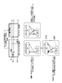
- FIG. 11 is a diagram showing an outline of a radio communication system according to fourth to ninth embodiments of the present invention. It is a block diagram which shows the structural example of the data transmission station 1100 in 4th Embodiment. It is a block diagram which shows the structural example of the data receiving station 1200 in the embodiment. 6 is a time chart showing an example of communication operation of the wireless communication system in the embodiment. It is a block diagram which shows the structural example of the data transmission station 1300 in 5th Embodiment.
- FIG. 1 shows a configuration example of a radio communication system based on SU-MIMO.
- the wireless communication system includes a data transmission station 100 and a data reception station 200.
- the direction from the data transmission station 100 to the data reception station 200 is referred to as “downlink”.
- the direction from the data receiving station 200 to the data transmitting station 100 is referred to as “uplink”.
- the data transmission station 100 generates a wireless packet.
- the generated wireless packet may include an identifier for identifying the data transmitting station 100 and an identifier for identifying the data receiving station 200.
- the data transmission station 100 performs wireless packet communication with the data reception station 200. This wireless packet communication can be divided into (i) calibration step, (ii) uplink channel estimation step, and (iii) downlink data transmission step.
- this wireless packet communication may be a communication using the same frequency channel by a CSMA / CA (Carrier Sense Multiple Access / Collision avoidance) method.
- the data transmission station 100 is, for example, an access point (AP) in a wireless LAN (Local
- the data receiving station 200 (STA: Station) performs wireless packet communication with the data transmitting station 100.
- the data receiving station 200 is a device that is a destination of a wireless packet generated by the data transmitting station 100.
- the data receiving station 200 is, for example, a computer or a portable information electronic device.
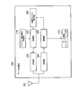
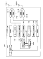
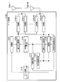
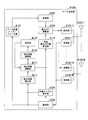
- FIG. 2 is a block diagram illustrating a configuration example of the data transmission station.
- the data transmission station 100 includes an antenna 102, a reception unit 104, a demodulation unit 109, a propagation channel estimation unit 108, a transmission weight value calculation unit 116, a correction value calculation unit 115, a data conversion interface unit 110, a channel
- the estimation signal generation unit 114, the modulation unit 105, the weighting calculation unit 106, and the transmission unit 103 are provided.
- the antenna 102 transmits / receives a signal indicating a wireless packet to / from the data receiving station 200.
- the data transmission station 100 includes a plurality (N) of antennas 102. That is, the data transmission station 100 is provided with an antenna 102-n (n is an arbitrary integer from 1 to N).
- antenna 102-n items common to all of the antennas 102-n are denoted by “antenna 102” with the symbol “ ⁇ n” omitted.
- the transmission unit 103 is provided for each antenna 102 in the data transmission station 100.
- a signal indicating a radio packet to be transmitted downstream is input from the weighting calculation unit 106 to the transmission unit 103-n (n is an arbitrary integer from 1 to N).
- transmission unit 103 items common to all of the transmission units 103-n are referred to as “transmission unit 103” by omitting the symbol “ ⁇ n”.
- the transmission unit 103 converts the frequency of a signal indicating a wireless packet to be transmitted downward into a predetermined frequency defined by the wireless communication system. In addition, the transmission unit 103 adjusts the transmission power of a signal indicating a radio packet to be transmitted in downlink, and outputs a signal indicating the radio packet to be transmitted to the antenna 102-n.
- the receiving unit 104 is provided in the data transmitting station 100 for each antenna 102.
- the receiving unit 104-n (n is an arbitrary integer from 1 to N) converts the frequency of a signal indicating a radio packet received via the antenna 102-n into a predetermined frequency.
- the reception unit 104-n performs adjustment of received power of a signal indicating the uplink received radio packet and outputs a signal indicating the radio packet to the demodulation unit 109.
- reception unit 104 items common to all of the reception units 104-n are denoted by “reception unit 104” by omitting the symbol “ ⁇ n”.
- the demodulator 109 receives a signal indicating an uplink received radio packet from the receiver 104-n.
- Demodulation section 109 performs demodulation processing on the signal indicating the radio packet received upstream.
- Demodulation section 109 outputs a signal indicating the demodulated radio packet to propagation channel estimation section 108, correction value calculation section 115, and data conversion interface section 110.
- the signal indicating the demodulated radio packet is the uplink transmission channel information feedback (CSI-FB: Channel State Information-Feedback)
- the demodulation unit 109 converts the downlink propagation channel information into the correction value calculation unit.
- 115 is output.
- the propagation channel estimation unit 108 receives a signal indicating the demodulated radio packet from the demodulation unit 109.
- a signal indicating a demodulated radio packet is propagation channel information feedback (CSI-FB).
- Propagation channel estimation section 108 estimates uplink propagation channel information based on a preamble (predetermined signal) of propagation channel information feedback, and uses the estimated uplink propagation channel information as correction value calculation section 115 and transmission weighting. It outputs to the value calculation part 116.
- CSI-FB propagation channel information feedback
- the signal indicating the demodulated radio packet includes, for example, an uplink transmitted propagation channel estimation signal (null data packet (NDP)).
- NDP downlink transmitted propagation channel estimation signal
- the propagation channel estimation unit 108 estimates uplink propagation channel information based on the uplink transmission channel estimation signal, and sends the estimated uplink propagation channel information to the correction value calculation unit 115 and the transmission weight value calculation unit 116. Output.
- the estimated downlink propagation channel information is input from the demodulation unit 109 to the correction value calculation unit 115. Further, the estimated uplink propagation channel information is input from the propagation channel estimation unit 108 to the correction value calculation unit 115.
- the correction value calculation unit 115 calculates a correction value for calibrating the difference between the uplink propagation channel information and the downlink propagation channel information based on the uplink propagation channel information and the downlink propagation channel information.
- the correction value calculation unit 115 outputs information indicating the correction value to the transmission weight value calculation unit 116.
- the estimated uplink propagation channel information is input from the propagation channel estimation unit 108 to the transmission weight value calculation unit 116. Further, information indicating the correction value is input from the correction value calculation unit 115 to the transmission weight value calculation unit 116.
- the transmission weight value calculator 116 calculates a transmission weight value (transmission weight) based on the estimated uplink propagation channel information and the information indicating the correction value, and sends the information indicating the transmission weight value to the weight calculator 106. Output.
- a ZF (Zero Forcing) method a MMSE (Minimum Mean Squared Error) method, or the like, which is a linear calculation method
- a THP (TomlinsonasHarashima Precoding) method, a VP (Vector Perturbation) method, or the like which is a method based on a non-linear operation, may be used.
- a signal indicating the demodulated radio packet is input from the demodulation unit 109 to the data conversion interface unit 110.
- the data conversion interface unit 110 is located at the boundary between the physical layer and the medium access control layer.
- the data conversion interface unit 110 converts the demodulated radio packet into a data packet of a predetermined format, and transmits a signal indicating the converted data packet to an external network (not shown).
- the data conversion interface unit 110 receives a signal indicating a data packet of a predetermined format from an external network (not shown).
- the data conversion interface unit 110 converts a signal indicating a data packet received from an external network (not shown) into a predetermined data signal, and outputs the converted data signal to the modulation unit 105.
- the channel estimation signal generation unit 114 generates a propagation channel estimation signal (NDP) for estimating the propagation channel information, and outputs the propagation channel estimation signal to the modulation unit 105.
- NDP propagation channel estimation signal
- the propagation channel estimation signal is a known signal.
- the converted data signal is input from the data conversion interface unit 110 to the modulation unit 105. Further, the propagation channel estimation signal is input from the channel estimation signal generation unit 114 to the modulation unit 105. Modulation section 105 modulates the converted data signal into a signal indicating a radio packet, and outputs a signal indicating the modulated radio packet to weighting calculation section 106. Modulation section 105 may modulate the propagation channel estimation signal into a signal indicating a radio packet, and output the signal indicating the modulated radio packet to weighting calculation section 106.
- a signal indicating a modulated wireless packet is input from the modulation unit 105 to the weighting calculation unit 106.
- information indicating the transmission weight value is input from the transmission weight value calculation unit 116 to the weight calculation unit 106.
- the weighting calculation unit 106 generates a signal indicating a radio packet to be transmitted in the downlink by multiplying a signal indicating the modulated radio packet by a transmission weight value (weighting synthesis).
- the weighting calculation unit 106 outputs a signal indicating a radio packet to be transmitted to the transmission unit 103-n.
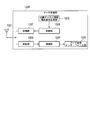
- FIG. 3 is a block diagram illustrating a configuration example of the data receiving station.
- the data reception station 200 includes an antenna 202, a transmission unit 203, a reception unit 204, a modulation unit 205, a propagation channel estimation unit 208, a demodulation unit 209, a data conversion interface unit 210, and a channel estimation signal generation unit 214. And comprising.
- the antenna 202 transmits and receives a signal indicating a wireless packet to and from the data transmission station 100.
- the description will be continued assuming that the data receiving station 200 is provided with one antenna 202.
- a signal indicating a radio packet to be transmitted upstream is input from the modulation unit 205 to the transmission unit 203.
- the transmission unit 203 converts the frequency of a signal indicating a radio packet to be transmitted in uplink to a predetermined frequency defined by the radio communication system.
- the transmission unit 203 performs adjustment of transmission power of a signal indicating a radio packet to be transmitted in uplink, and outputs a signal indicating a radio packet to be transmitted to the antenna 202.
- the receiving unit 204 converts the frequency of the signal indicating the radio packet received via the antenna 202 to a predetermined frequency. In addition, the reception unit 204 performs adjustment of reception power of a signal indicating a downlink received radio packet, and outputs a signal indicating the radio packet to the demodulation unit 209.
- a signal indicating a downlink received radio packet is input from the receiving unit 204 to the demodulating unit 209.
- the demodulation unit 209 performs demodulation processing on the signal indicating the downlink received wireless packet.
- Demodulation section 209 outputs a signal indicating the demodulated radio packet to propagation channel estimation section 208 and data conversion interface section 210.
- a signal indicating the demodulated radio packet is input from the demodulation unit 209 to the data conversion interface unit 210.
- the data conversion interface unit 210 is located at the boundary between the physical layer and the medium access control layer.
- the data conversion interface unit 210 converts the demodulated radio packet into a data packet of a predetermined format, and transmits a signal indicating the converted data packet to an external network (not shown).
- the data conversion interface unit 210 may receive a signal indicating a data packet of a predetermined format from an external network (not shown).
- the data conversion interface unit 210 may convert a signal indicating a data packet received from an external network (not shown) into a predetermined data signal, and output the converted data signal to the modulation unit 205.
- a signal indicating the demodulated radio packet is input to the propagation channel estimation unit 208 from the demodulation unit 209.
- the signal indicating the demodulated radio packet includes, for example, a downlink transmission channel estimation signal (NDP).
- NDP downlink transmission channel estimation signal
- Propagation channel estimation unit 208 compares the propagation channel estimation signal transmitted in the downlink with a predetermined propagation channel estimation signal.
- the propagation channel estimation unit 208 estimates downlink propagation channel information based on the comparison result, and outputs the estimated downlink propagation channel information to the modulation unit 205.
- the channel estimation signal generation unit 214 generates a propagation channel estimation signal and outputs the propagation channel estimation signal to the modulation unit 205. It is assumed that the propagation channel estimation signal is a known signal.
- the propagation channel estimation signal is input from the channel estimation signal generation unit 214 to the modulation unit 205. Also, the estimated downlink propagation channel information is input from the propagation channel estimation unit 208 to the modulation unit 205.
- Modulation section 205 modulates the converted data signal into a signal indicating a radio packet, and outputs a signal indicating the modulated radio packet to transmission section 203.
- the modulation unit 205 modulates the propagation channel estimation signal (NDP) into a signal indicating a radio packet, and outputs a signal indicating the modulated radio packet to the transmission unit 203.
- Modulation section 205 modulates the estimated downlink propagation channel information into a signal indicating a radio packet, and outputs a signal (CSI-FB) indicating the modulated radio packet to transmission section 203.
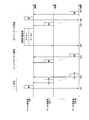
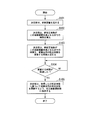
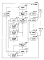
- FIG. 4 is a timing chart illustrating an example of an operation procedure of the wireless communication system.
- the wireless packet communication shown in this timing chart can be divided into (i) calibration step, (ii) uplink channel estimation step, and (iii) downlink data transmission step.
- the operation procedure shown in this timing chart is repeatedly executed.
- the calibration step includes steps S1 and S2.
- the uplink channel estimation step includes step S3.
- the downlink data transmission step includes steps S4 and S5.
- Step S1 The antenna 102-n (see FIG. 2) of the data transmission station 100 transmits a propagation channel estimation signal (NDP) (training signal) to the data reception station 200.
- NDP propagation channel estimation signal
- Step S2 The antenna 202 (see FIG. 3) of the data receiving station 200 transmits propagation channel information feedback (CSI-FB) to the data transmitting station 100.
- Demodulation section 109 estimates downlink propagation channel information based on the demodulated propagation channel information feedback.
- Demodulation section 109 outputs the estimated downlink propagation channel information to correction value calculation section 115.
- the propagation channel estimation unit 108 estimates uplink propagation channel information based on the preamble of propagation channel information feedback (CSI-FB), and the estimated uplink propagation channel information is converted into a correction value calculation unit 115 and It outputs to the transmission weight value calculation part 116.
- CSI-FB propagation channel information feedback
- Downlink propagation channel information is input from the demodulation unit 109 to the correction value calculation unit 115 (see FIG. 2). Further, uplink propagation channel information is input from the propagation channel estimation unit 108 to the correction value calculation unit 115.
- the correction value calculation unit 115 calculates a correction value C for calibrating the difference between the uplink propagation channel information and the downlink propagation channel information based on the uplink propagation channel information and the downlink propagation channel information. .
- Downlink propagation channel information H D is represented by formula (1).
- G RS indicates the characteristics of the receiving unit 204 and the antenna 202 of the data receiving station 200.
- H indicates a response (communication path response) of propagation channel information in the air.
- GTA indicates the characteristics of the transmission unit 103 and the antenna 102 of the data transmission station 100. GTA is represented by Formula (2).
- uplink propagation channel information H U is represented by the formula (3).
- G TS indicates the characteristics of the transmission unit 203 and the antenna 202 of the data receiving station 200.
- GRA indicates the characteristics of the receiving unit 104 and the antenna 102 of the data transmission station 100.
- T on the right shoulder of [G RA HG TS ] shown in Formula (3) represents transposition.
- G RA is expressed by Equation (4).
- the correction value calculation unit 115 calculates the correction value C based on the downlink propagation channel information H D and the uplink propagation channel information H U.
- the correction value C is expressed by equation (5).
- correction value calculation unit 115 also repeatedly transmits (for example, M times) the propagation channel estimation signal (uses time diversity) in wireless packet communication for a predetermined period (for example, the calibration step shown in FIG. 4). A highly accurate correction value C can be obtained.
- the transmission weight value calculation unit 116 the uplink propagation channel information H U is input from the propagation channel estimation unit 108.
- Information indicating the correction value C is input from the correction value calculation unit 115 to the transmission weight value calculation unit 116.
- Transmission weighting value calculating unit 116 as shown in equation (6), the uplink propagation channel information H U, is multiplied by the correction value C from the right.
- the transmission weight value calculation unit 116 calculates a transmission weight value based on the multiplied information H U ′, and outputs information indicating the transmission weight value to the weight calculation unit 106.
- the temporary correction value c n (m) for each antenna 202 of the data reception station 200 is expressed by Expression (7).
- the n 0th antenna 102-n 0 is a reference antenna.
- This component is composed of the n-th transmitter 103-n and the antenna 102-n of the data transmission station 100.
- the transmission weight value calculation unit 116 calculates a transmission weight value (transmission weight) based on the estimated uplink propagation channel information and the correction value C, and weights the information indicating the transmission weight value. The result is output to the calculation unit 106. Since the transmission weight value calculation unit 116 calculates the transmission weight value based on the highly accurate correction value C, the transmission weight value can be calculated with high accuracy.
- the weighting calculation unit 106 (see FIG. 2) generates a signal indicating a radio packet to be transmitted by multiplying a signal indicating the modulated radio packet by a transmission weight value (weighting synthesis).
- CSI-FB propagation channel information feedback
- NDP propagation channel estimation signal
- Component c n of the correction value C is, for example, represented by the formula (8).
- Equation (9) weighting a n (m) represented by is a weighting method that is based on each channel gain. Since this weighting method gives priority to a highly reliable correction value (optimal correction value), the accuracy can be improved.
- weighting a n (m) may be represented by the formula (10). Weighting a n (m) of the formula (10) is a weighting method based on channel gain.
- Step S3 The antenna 202 of the data receiving station 200 transmits a propagation channel estimation signal (NDP) to the data transmitting station 100.
- NDP propagation channel estimation signal
- the propagation channel estimation unit 108 estimates uplink propagation channel information based on the propagation channel estimation signal in order to transmit downlink data.
- the transmission weight value calculation unit 116 calculates a transmission weight value (transmission weight) based on the estimated uplink propagation channel information and information indicating the correction value C, and indicates the transmission weight value Is output to the weighting calculation unit 106.
- the weighting calculation unit 106 multiplies (weights and combines) a transmission weight value by a signal indicating a modulated radio packet.
- the transmission unit 103 adjusts the transmission power of a signal indicating a radio packet to be transmitted in downlink, and outputs a signal indicating the radio packet to be transmitted to the antenna 102-n.
- the antenna 102 transmits a signal indicating a radio packet (data 1 in FIG. 4) to be transmitted to the data receiving station 200 by spatial multiplexing transmission.
- Step S5 When the demodulator 209 (see FIG. 3) decodes the signal indicating the downlink transmitted radio packet (data 1 in FIG. 4) without error, the data receiving station 200 receives a predetermined confirmation signal ( BA: Block Acknowledgement) is transmitted to the data transmission station 100.
- a predetermined confirmation signal BA: Block Acknowledgement
- the data transmission station 100 has received from the data reception station 200 together with the downlink propagation channel information indicating the propagation channel from the data transmission station 100 to the data reception station 200 (other wireless communication apparatus).
- a propagation channel estimation unit for estimating first uplink propagation channel information indicating a propagation channel from the data receiving station 200 to the data transmitting station 100 based on a predetermined signal (for example, a preamble), and downlink propagation channel information
- a first uplink propagation channel information (estimated in the calibration step)
- a temporary correction value c n (m) is calculated, and a weight a n (m) based on the channel gain is set as the temporary correction value c n ( by combining by multiplying m) (e.g., the formula (8) above), the correction value C (e.g., equation (5) correction value calculating unit 115 for calculating a reference to)
- Transmission weighting for calculating a transmission weight value based on the correction value C and the first uplink propag
- the wireless communication system is configured to transmit data from the data receiving station 200 to the data transmitting station 100 based on a predetermined signal received from the data receiving station 200 together with downlink propagation channel information indicating a propagation channel from the data transmitting station 100 to the data receiving station 200.
- the radio communication method of the present embodiment is a radio communication method in a radio communication device, in which the propagation channel estimation unit 108 communicates with other radio communication together with downlink propagation channel information indicating a propagation channel from the own radio communication device to another radio communication device.
- the transmission weight value calculation unit 116 determines the transmission weight value based on the correction value and the first uplink propagation channel information or the second uplink propagation channel information. Calculating, the transmitter 103 has a transmission weighting value, a second uplink propagation channel information, the beam formed on the basis of the steps of wirelessly transmitting a predetermined signal to another wireless communication apparatus.
- the correction value calculation unit 115 calculates the temporary correction value c n (m) based on the downlink propagation channel information and the first uplink propagation channel information (estimated in the calibration step ) , and the channel gain
- the correction value C is calculated by multiplying the temporary correction value c n (m) by the weighting a n (m) based on and synthesizing. Accordingly, the wireless communication device, the wireless communication system, and the wireless communication method according to the first embodiment have high communication quality by SU-MIMO transmission.
- the radio communication system calculates a transmission weight value based on the uplink propagation channel information, and performs SU-MIMO transmission based on the calculated transmission weight value.
- the wireless communication system according to the first embodiment can improve the effective throughput by correcting the propagation channel information based on the characteristic difference information between the data transmitting station 100 and the data receiving station 200.
- the wireless communication system does not simply handle the provisional correction value (for example, the provisional correction value using time diversity) by the data receiving station 200, so that the provisional correction value with low estimation accuracy is low.
- the accuracy of the correction value C is not deteriorated by being dragged by the correction value.
- the wireless communication system according to the first embodiment weights the data receiving station 200 based on the channel gain.
- the radio communication system according to the first embodiment may use time diversity as described above. Thereby, the wireless communication system according to the first embodiment gives priority to the temporary correction value c n (m) with high reliability based on the weighting a n (m) , and calculates the highly accurate correction value C.
- communication quality in SU-MIMO can be improved.
- the propagation channel estimation unit 108 may estimate a plurality of pieces of first uplink propagation channel information based on a plurality of predetermined signals (for example, preambles).
- the correction value calculation unit 115 may calculate a plurality of temporary correction values based on a plurality of downlink propagation channel information and a plurality of first uplink propagation channel information. That is, the wireless communication system may acquire the provisional correction value by repeatedly transmitting a known signal in time (using time diversity).
- the transmission weight value calculation unit 116 may calculate the transmission weight value based on the first uplink propagation channel information before the second uplink propagation channel information is estimated (calibration step). That is, when the data transmission station 100 calculates the correction value, the wireless communication system performs selection of the transmission antenna and the reference antenna for canceling the transmission / reception circuit response component of the data reception station 200 during the calibration step. A correct correction value may be used.
- the transmission weight value calculation unit 116 may calculate the transmission weight value based on the second uplink propagation channel information when the second uplink propagation channel information is estimated (uplink channel estimation step). That is, the radio communication system may perform selection of the optimal transmission antenna and reference antenna during the uplink channel estimation step.
- the second embodiment is different from the first embodiment in that there are a plurality of data receiving stations (multiuser). In the second embodiment, only differences from the first embodiment will be described.
- FIG. 5 is a diagram illustrating a configuration example of a wireless communication system based on MU-MIMO.
- the wireless communication system includes a data transmission station 100 and data reception stations 200-1 to 200-M.
- the description is continued assuming that there are M data reception stations 200.
- items common to all of the data receiving stations 200-m are denoted by “data receiving station 200” by omitting the symbol “ ⁇ m”.
- the data transmission station 100 generates a wireless packet.
- the generated wireless packet may include an identifier for identifying the data transmitting station 100 and an identifier for identifying the data receiving stations 200-1 to 200-M.
- the data transmitting station 100 performs wireless packet communication with the data receiving stations 200-1 to 200-M.
- This wireless packet communication can be divided into (i) calibration step, (ii) uplink channel estimation step, and (iii) downlink data transmission step.
- this wireless packet communication may be communication using the same frequency channel by the CSMA / CA method.
- the data receiving station 200 performs wireless packet communication with the data transmitting station 100.
- the data receiving station 200 is a device that is a destination of a wireless packet generated by the data transmitting station 100.
- the data receiving station 200 is, for example, a computer or a portable information electronic device.
- FIG. 6 is a timing chart showing an operation procedure example of the wireless communication system.
- the wireless packet communication shown in this timing chart can be divided into (i) a calibration step, (ii) an uplink channel estimation step, and (iii) a downlink data transmission step.
- the operation procedure shown in this timing chart is repeatedly executed.
- the calibration step includes steps Sa1 and Sa2.
- the uplink channel estimation step includes step Sa3. Further, the downlink data transmission step includes steps Sa4 to Sa7.
- Step Sa1 The antenna 102-n (see FIG. 2) of the data transmitting station 100 transmits a propagation channel estimation signal (NDP) (training signal) to the data receiving stations 200-1 to 200-M.
- NDP propagation channel estimation signal
- Step Sa2 Each antenna 202 (see FIG. 3) of the data receiving stations 200-1 to 200-M transmits propagation channel information feedback (CSI-FB) to the data transmitting station 100.
- the demodulation unit 109 estimates any or all downlink propagation channel information of the data reception station 200 based on the propagation channel information feedback received and demodulated from any or all of the data reception stations 200. To do.
- Demodulation section 109 outputs any or all estimated downlink propagation channel information of data reception station 200 to correction value calculation section 115.
- the propagation channel estimation unit 108 estimates the uplink propagation channel information based on the preamble of any or all propagation channel information feedback (CSI-FB) of the data reception station 200, and Any or all of the estimated uplink propagation channel information is output to the correction value calculation section 115 and the transmission weight value calculation section 116.
- CSI-FB propagation channel information feedback
- the estimated downlink propagation channel information of any or all of the data reception stations 200 is input from the demodulation unit 109 to the correction value calculation unit 115. Further, the estimated propagation channel information of any or all of the data reception stations 200 is input to the correction value calculation unit 115 from the propagation channel estimation unit 108.
- the correction value calculation unit 115 determines whether the uplink propagation channel information and the downlink propagation channel are based on any or all uplink propagation channel information of the data reception station 200 and any or all downlink propagation channel information of the data reception station 200. A correction value for calibrating the difference in information is calculated. The correction value calculation unit 115 outputs information indicating the correction value to the transmission weight value calculation unit 116.
- the transmission weight value calculation unit 116 receives any or all estimated uplink propagation channel information of the data reception station 200 from the propagation channel estimation unit 108. Further, information indicating the correction value is input from the correction value calculation unit 115 to the transmission weight value calculation unit 116.
- the transmission weight value calculation unit 116 calculates a transmission weight value (transmission weight) based on any or all estimated uplink propagation channel information of the data receiving station 200 and information indicating the correction value, and transmits the transmission weight value. Is output to the weighting calculation unit 106.
- N reference antennas (n 0th antennas) of the data transmission station 100 can be considered.
- component c n of the correction value C shown in Equation (8) it is possible to calculate N Street.
- Correction value calculating unit 115 among the components c n of the correction value C N-way, the most accurate correction value C component c n, selects the calibration step.
- This selection method may be, for example, a method in which the data transmission station 100 executes beam forming that becomes a null signal in the data reception station 200 and selects the one whose power is closest to the value 0.
- Step Sa3 Each antenna 202 of the data receiving stations 200-1 to 200-M transmits a propagation channel estimation signal (NDP) to the data transmitting station 100.
- the correction value calculation unit 115 selects N reference antennas (n 0th antenna) for Expression (7).
- Step Sa4 The transmission unit 103 of the data transmission station 100 performs adjustment of transmission power of a signal indicating a radio packet to be transmitted in downlink, and outputs a signal indicating the radio packet to be transmitted to the antenna 102-n.
- Antenna 102 transmits a signal indicating a radio packet to be transmitted in the downlink (data 1 and data 2 in FIG. 6) to data receiving stations 200-1 to 200-M by spatial multiplexing transmission.
- Step Sa5 When the demodulator 209 (see FIG. 3) decodes a signal indicating a radio packet to be transmitted (data 1 or data 2 in FIG. 6) without error, the data receiving station 200-1
- the confirmation signal (BA) is transmitted to the data transmission station 100.
- Step Sa6 The transmission unit 103 of the data transmission station 100 transmits a signal (BAR: BA request) for requesting a predetermined confirmation signal to the data reception station 200-M.
- BAR BA request
- M-1 the data receiving stations 200-2 to 200- (M-1).
- Step Sa7 The data receiving station 200-M, when the demodulator 209 (see FIG. 3) decodes the signal indicating the radio packet to be transmitted (data 1 or data 2 in FIG. 6) without error,
- the confirmation signal (BA) is transmitted to the data transmission station 100.
- the data transmission station 100 (wireless communication apparatus) is determined in advance from the data reception station 200-m together with the downlink propagation channel information indicating the propagation channel from the data transmission station 100 to the data reception station 200-m.
- the propagation channel estimation unit 108 that estimates the first uplink channel information indicating the propagation channel from the data receiving station 200 to the data transmitting station 100, the downlink channel information,
- the temporary correction value c n (m) is calculated based on the uplink propagation channel information of 1 (estimated in the calibration step), and the weighting a n (m) based on the channel gain is set as the temporary correction value c n (m) .
- the correction value calculation unit 115 that calculates the correction value C, the correction value C, and the first uplink propagation channel information or the second uplink propagation channel.
- Transmission weight value calculation unit 116 that calculates a transmission weight value based on the transmission information (estimated in the calibration step or estimated in the uplink channel estimation step), the transmission weight value, and the second uplink propagation channel information ( And a transmission unit 103 that wirelessly transmits a predetermined signal to the data reception station 200-m using a beam formed based on the uplink channel estimation step.
- the wireless communication system is configured to transmit data from the data receiving station 200 to the data transmitting station 100 based on a predetermined signal received from the data receiving station 200 together with downlink propagation channel information indicating a propagation channel from the data transmitting station 100 to the data receiving station 200.
- the radio communication method of the present embodiment is a radio communication method in a radio communication device, in which the propagation channel estimation unit 108 communicates with other radio communication together with downlink propagation channel information indicating a propagation channel from the own radio communication device to another radio communication device.
- the transmission weight value calculation unit 116 determines the transmission weight value based on the correction value and the first uplink propagation channel information or the second uplink propagation channel information. Calculating, the transmitter 103 has a transmission weighting value, a second uplink propagation channel information, the beam formed on the basis of the steps of wirelessly transmitting a predetermined signal to another wireless communication apparatus.
- the correction value calculation unit 115 calculates the temporary correction value c n (m) based on the downlink propagation channel information and the first uplink propagation channel information (estimated in the calibration step ) , and the channel gain
- the correction value C is calculated by multiplying the temporary correction value c n (m) by the weighting a n (m) based on and synthesizing. Accordingly, the wireless communication device, the wireless communication system, and the wireless communication method according to the second embodiment have high communication quality by MU-MIMO transmission.
- the radio communication system according to the second embodiment calculates a transmission weight value based on the uplink propagation channel information, and executes MU-MIMO transmission based on the calculated transmission weight value.
- the wireless communication system according to the second embodiment can improve the effective throughput by correcting the propagation channel information based on the characteristic difference information between the data transmitting station 100 and the data receiving station 200-m. .
- the wireless communication system according to the second embodiment does not simply handle the provisional correction value by the data receiving station 200-m, so it is dragged to the provisional correction value with low estimation accuracy and the correction value C The accuracy does not deteriorate.
- the radio communication system according to the second embodiment weights the data reception station 200-m based on the channel gain.
- the radio communication system according to the second embodiment may use time diversity as described above.
- the wireless communication system according to the second embodiment gives priority to the temporary correction value c n (m) with high reliability based on the weighting a n (m) , and calculates the high-accuracy correction value C.
- the communication quality in MU-MIMO can be further improved.
- the correction value calculation unit 115 may calculate a plurality of temporary correction values for each antenna of a plurality of other wireless communication devices. That is, in the wireless communication system, the data transmission station may acquire temporary correction values for each of a plurality of antennas on the partner station side.
- the third embodiment is different from the first embodiment and the second embodiment in that the wireless communication system includes a network control server. In the third embodiment, only differences from the first embodiment and the second embodiment will be described.
- FIG. 7 is a block diagram showing a configuration example of a wireless communication system based on network control.
- the wireless communication system includes data transmitting stations 100-1 to 100-2, data receiving stations 200-1 to 200-M, and a network control server 300 (server device).
- the data transmission station 100-1 is fixedly installed, and transmits uplink propagation channel information and downlink propagation channel information to the network control server 300.
- the data transmission station 100-1 receives information indicating the correction value C or information indicating the transmission weight value from the network control server 300.
- the data transmission station 100-2 is fixedly installed and transmits uplink propagation channel information and downlink propagation channel information to the network control server 300.
- the data transmission station 100-2 receives the information indicating the correction value C or the information indicating the transmission weight value from the network control server 300.
- the network control server 300 is connected to the data transmission station 100-1 and the data transmission station 100-2 by wire.
- the network control server 300 relays data communication between the data transmission station 100-1 and the data transmission station 100-2.
- the network control server 300 receives uplink propagation channel information and downlink propagation channel information from the data transmission station 100-1 and the data transmission station 100-2.
- the network control server 300 calculates the correction value C based on the uplink propagation channel information and the downlink propagation channel information, similarly to the correction value calculation unit 115 (see FIG. 2).
- the network control server 300 calculates a transmission weight value (transmission weight). Then, the network control server 300 notifies the data transmission station 100-1 and the data transmission station 100-2 of the information indicating the correction value C or the information indicating the transmission weight value.
- FIG. 8 is a timing chart showing an operation procedure example of the wireless communication system.
- the wireless packet communication shown in this timing chart can be divided into (i) a calibration step, (ii) an uplink channel estimation step, and (iii) a downlink data transmission step.
- the operation procedure shown in this timing chart is repeatedly executed.
- the calibration step includes steps Sb1 to Sb3.
- the uplink channel estimation step includes step Sb4.
- the downlink data transmission step includes steps Sb5 to Sb8.
- Steps Sb1 and Sb2 are the same as steps Sa1 and Sa2 shown in FIG. 6 of the second embodiment. In this case, however, information (propagation channel estimation signal NDP) is notified between data transmission station 100-1 and data transmission station 100-2.
- Step Sb3 The network control server 300 calculates the correction value C and the transmission weight value, and sends the information indicating the correction value C or the information indicating the transmission weight value to the data transmission station 100-1 and the data transmission station 100-2. Notice.
- Steps Sb4 to Sb8 are the same as steps Sa3 to Sa7 shown in FIG. 6 of the second embodiment.
- the transmission unit 103 of the data transmission station 100 transmits at least one of the downlink propagation channel information, the first uplink propagation channel information, and the second uplink propagation channel information to the network control server 300. That is, the wireless communication system transmits and receives known signals between the data transmission station 100-1 and the data transmission station 100-2, and notifies the obtained channel estimation value via the network control server 300. To do.
- the network control server 300 estimates the accuracy of the correction value C due to the compression error associated with reporting the uplink propagation channel information and the downlink propagation channel information. Can be improved.
- a data transmission station as a radio communication apparatus acquires subcarrier propagation channel information or transmission weight values used in uplink transmission from a data reception station.
- the data transmitting station interpolates the propagation channel information or the transmission weight value in subcarriers other than the subcarrier from which the propagation channel information or the transmission weight value is acquired based on the acquired propagation channel information or the transmission weight value.
- the data transmitting station uses the propagation channel information or the transmission weight value obtained by the interpolation in the MU-MIMO transmission in the downlink.
- FIG. 9 is a diagram showing an outline of the radio communication system according to the fourth to ninth embodiments of the present invention.
- the wireless communication system includes a data transmission station 1100, and a data reception station 1200-1 and a data reception station 1200-2 that perform wireless packet communication with the data transmission station 1100.
- the data transmission station 1100, the data reception station 1200-1, and the data reception station 1200-2 use the CSMA / CA (Carrier Sense Multiple Access / Collision Avoidance) method and the same frequency channel.
- Wireless packet communication is performed using When transmitting data to the data receiving station 1200-1 and the data receiving station 1200-2, the data transmitting station 1100 performs spatial multiplexing transmission (MU-MIMO) using the same frequency band at the same time.
- MU-MIMO spatial multiplexing transmission
- the wireless packet transmitted and received in the wireless packet communication includes an identifier indicating the transmission station and the destination station.
- the transmitting station is a device that generates and transmits a wireless packet.
- a destination station is a device that is the destination of a wireless packet.
- the data transmission station 1100 is an access point or the like in a wireless LAN
- the data reception station 1200-1 and the data reception station 1200-2 are computers or portable information electronic devices in the wireless LAN.
- FIG. 9 shows an example in which the wireless communication system includes two data receiving stations 1200 (1200-1 and 1200-2), but the wireless communication system may include three or more data receiving stations 1200.
- One data receiving station 1200 may be provided.
- the propagation channel information in the downlink of the subcarrier number k between the data transmission station 1100 and the data reception station 1200-1 is Hd1 , k , and the data transmission station 1100 and the data reception station 1200-2 are Let Hd2, k be the propagation channel information in the downlink of the subcarrier number k between. Further, the propagation channel information on the uplink of the subcarrier number k between the data transmitting station 1100 and the data receiving station 1200-1 is set to H u1, k , and the data transmission station 1100 and the data receiving station 1200-2 are connected to each other. Let H u2, k be the propagation channel information in the uplink of the subcarrier number k.
- the wireless communication system includes a data transmission station 1100 and a plurality of data reception stations 1200.
- FIG. 10 is a block diagram illustrating a configuration example of the data transmission station 1100 according to the fourth embodiment.
- data transmission station 1100 includes antennas 1101-1 to 1101-N, reception units 1102-1 to 1102-N, demodulation unit 1103, propagation channel estimation unit 1104, and propagation channel calibration unit. 1105, a propagation channel interpolation unit 1106, a transmission weight value calculation unit 1107, a data conversion interface unit 1108, a modulation unit 1109, a weight calculation unit 1110, and transmission units 1111-1 to 1111-N. .
- Each of the reception units 1102-1 to 1102-N converts the frequency of the reception signal received via the connected antennas 1101-1 to 1101-N into a baseband frequency, and adjusts reception power and the like.
- the received signal that has been converted and adjusted is output to demodulation section 1103.
- the demodulator 1103 demodulates the received signals input from the receivers 1102-1 to 1102-N.
- Demodulation section 1103 outputs a propagation channel estimation signal (known signal) among the data signals obtained by demodulation to propagation channel estimation section 1104 and outputs the other data signals to data conversion interface section 1108.
- Propagation channel estimation section 1104 compares each of antennas 1101-1 to 1101-N with a data receiving station by comparing a propagation channel estimation signal input from demodulation section 1103 with a known propagation channel estimation signal. The propagation channel information for each subcarrier in the uplink with 1200 is estimated. The propagation channel estimation unit 1104 outputs the estimated propagation channel information to the propagation channel calibration unit 1105.
- Propagation channel calibration section 1105 calculates propagation channel information in the downlink from propagation channel information in the uplink using a calibration value predetermined for the propagation channel information input from propagation channel estimation section 1104. Propagation channel calibration section 1105 outputs the calculated downlink propagation channel information to propagation channel interpolation section 1106.
- the downlink propagation channel information H d, k is calculated using the following equation (11).
- the matrix H d, k is a matrix having the matrix H d1, k and the matrix H d2, k as elements.
- the matrix C k in equation (11) is a calibration matrix (calibration value) for calibrating the uplink propagation channel information H u, k to the downlink propagation channel information H d, k .
- the matrix H u, k is a matrix having the matrix H u1, k and the matrix H u2, k as elements.
- the propagation channel information is input from the propagation channel calibration unit 1105 to the propagation channel interpolation unit 1106.
- the propagation channel interpolation unit 1106 interpolates the propagation channel information for subcarriers other than the subcarriers of the propagation channel information input from the propagation channel calibration unit 1105 among all subcarriers used in the wireless communication system.
- the interpolation of the propagation channel information is performed by copying or averaging the input propagation channel information, for example.
- the propagation channel interpolation unit 1106 outputs the input propagation channel information and the propagation channel information obtained by the interpolation to the transmission weight value calculation unit 1107.
- the propagation channel information on the subcarriers other than the subcarriers of the propagation channel information input from the propagation channel calibration unit 1105 (hereinafter, subcarriers for which the propagation channel information is insufficient) is copied.
- subcarriers for which the propagation channel information is insufficient A case of interpolation will be described.
- Propagation channel interpolation section 1106 detects a subcarrier number closest to subcarrier number k of a subcarrier for which propagation channel information is insufficient, among subcarrier numbers of subcarriers of input propagation channel information.
- Propagation channel interpolation section 1106 copies the propagation channel information corresponding to the detected subcarrier number to the propagation channel information in the subcarrier of subcarrier number k. That is, the propagation channel interpolation unit 1106 interpolates the propagation channel information by the following equation (12).
- K with “ ⁇ (hat)” in the expression (12) is the subcarrier number closest to the subcarrier number k among the subcarrier numbers of the subcarriers in which the corresponding propagation channel information exists. Show. In the following, in a mathematical expression or the like, a character with “ ⁇ (hat)” attached above is represented by “ ⁇ ” in front of the character. For example, the propagation channel information on the right side of Expression (12) is expressed as “H d, ⁇ k ”.
- Propagation channel interpolation section 1106 calculates the average value of the propagation channel information of subcarriers in which the corresponding propagation channel information exists among the subcarriers near the subcarriers for which propagation channel information is insufficient.
- the propagation channel interpolation unit 1106 interpolates the calculated average value of the propagation channel information into propagation channel information of subcarriers for which the propagation channel information is insufficient.
- a nearby subcarrier is a subcarrier within a predetermined range.
- the propagation channel information corresponding to the subcarrier number k is (H d, k ⁇ 1 + H d, k + 1 ). / 2. Moreover, you may make it calculate the average value of propagation channel information using following Formula (13). N represents an average number.
- the transmission weight value calculation unit 1107 calculates a transmission weight value corresponding to each subcarrier based on the downlink propagation channel information input from the propagation channel interpolation unit 1106.
- the transmission weight value calculation unit 1107 outputs the calculated transmission weight value to the weight calculation unit 1110.
- a linear calculation uses a ZF (Zero Forcing) method or an MMSE (Minimum Mean Squared Error) method
- a non-linear calculation uses a THP (Tomlinson Harashima Precoding) method or VP. (Vector Perturbation) method or the like can be used. Note that the transmission weight value calculation unit 1107 calculates the transmission weight value using any one of the above-described methods or another method.
- the data conversion interface unit 1108 converts the data signal input from the demodulation unit 1103 into a packet used in an external device, and outputs the packet obtained by the conversion to an external device or an external network.
- the data conversion interface unit 1108 converts a packet input from an external device or an external network into a data signal, and outputs the data signal obtained by the conversion to the modulation unit 1109.
- Modulation section 1109 modulates the data signal input from data conversion interface section 1108 to generate a radio packet signal, and outputs the generated radio packet signal to weighting calculation section 1110.
- the weighting calculation unit 1110 receives a radio packet signal from the modulation unit 1109 and a transmission weight value from the transmission weight value calculation unit 1107. Weighting calculation section 1110 multiplies the radio packet signal for each transmission weighting value and outputs a transmission signal indicating the multiplication result to transmission sections 1111-1 to 1111 -N.
- Each of the transmission units 1111-1 to 1111-N converts the frequency of the transmission signal input from the weighting calculation unit 1110 to a radio frequency defined in the wireless communication system, adjusts transmission power, etc.
- the adjusted transmission signal is transmitted from the antennas 1101-1 to 1101-N.
- the data transmission station 1100 can multiplex and transmit data addressed to each data reception station 1200.
- FIG. 11 is a block diagram showing a configuration example of the data receiving station 1200 in the present embodiment.
- the data reception station 1200 includes an antenna 1201, a reception unit 1202, a demodulation unit 1203, a data conversion interface unit 1204, a propagation channel information estimation signal generation unit 1205, a modulation unit 1206, a transmission unit Part 1207.
- the receiving unit 1202 converts the frequency of the received signal received via the connected antenna 1201 into a baseband frequency, adjusts received power, and the like, and converts the received signal that has been converted and adjusted to the demodulating unit 1203. Output.
- the demodulator 1203 demodulates the received signal input from the receiver 1202.
- Demodulation section 1203 outputs the data signal obtained by demodulation to data conversion interface section 1204.
- the data conversion interface unit 1204 converts the data signal input from the demodulation unit 1203 into a packet used in an external device, and outputs the packet obtained by the conversion to an external device or an external network.
- Propagation channel information estimation signal generation section 1205 generates a propagation channel estimation signal (known signal) and outputs the generated signal to modulation section 1206.
- Modulation section 1206 modulates the propagation channel estimation signal input from propagation channel information estimation signal generation section 1205 and the signal transmitted to data transmission station 1100 to generate a radio packet signal. Modulation section 1206 outputs the generated radio packet signal to transmission section 1207.
- the transmission unit 1207 converts the frequency of the radio packet signal input from the modulation unit 1206 into a radio frequency defined in the radio communication system, adjusts transmission power, etc., and performs the conversion and adjustment of the radio packet signal that has been converted and adjusted. Is transmitted from the antenna 1201.
- FIG. 12 is a time chart showing a communication operation example of the wireless communication system in the present embodiment.
- a part of operations when data transmission station 1100 continuously generates packets addressed to data reception station 1200-1 and data reception station 1200-2 and data transmission is performed continuously. It is shown.
- the data receiving station 1200-1 acknowledgment signal to the received data prior to time T 1 to the data transmission station 1100 addressed (Block Acknowledge: BA) and transmits the.
- the response confirmation signal is transmitted in the form of “20 MHz ⁇ 4 arrangement” so that the data transmission station or the data reception station of the conventional standard can receive the response confirmation signal.
- Data transmission station 1100 after receiving an acknowledgment signal from the data receiving station 1200-1, the packet signal containing the data transmitted to the data receiving station 1200-2 prior to time T 1 is the data receiving station 1200-2
- a response confirmation instruction signal (Block Acknowledge Request: BAR) for instructing transmission of a response confirmation signal is transmitted to the data receiving station 1200-2.
- the data reception station 1200-2 When receiving a response confirmation instruction signal from the data transmission station 1100, the data reception station 1200-2 transmits a response confirmation signal according to the instruction.
- the transmission of the response confirmation signal by the data reception station 1200-2 is also performed in the format of “20 MHz ⁇ 4 arrangement”.
- Data transmission station 1100 estimates uplink propagation channel information based on a known signal (propagation channel estimation signal) included in the response confirmation signal received from each data reception station 1200.
- the data transmission station 1100 calculates a transmission weight after performing calibration and interpolation of the propagation channel on the estimated uplink propagation channel information.
- the data transmission station 1100 uses the calculated transmission weight value to transmit a radio packet signal including data (Data 1) addressed to the data reception station 1200-1 and data (Data 2) addressed to the data reception station 1200-2.
- MU-MIMO performs transmission with a wireless packet signal including
- data receiving station 1200-1 decodes the data (Data 1) addressed to its own data receiving station transmitted at time T 2 without error
- data receiving station 1200-1 transmits a response confirmation signal (BA) to data transmitting station 1100.
- BA response confirmation signal
- Data transmission station 1100 after receiving an acknowledgment signal from the data receiving station 1200-1, the data receiving station 1200-2 data (Data2) which was sent to the data receiving station 1200-2 at time T 2, the error-free decoding
- a response confirmation instruction signal (Block Acknowledge Request: BAR) for instructing transmission of a response confirmation signal is transmitted to the data receiving station 1200-2.
- BAR Block Acknowledge Request
- the data reception station 1200-2 transmits a response confirmation signal according to the instruction.
- the data transmitting station 1100 acquires uplink propagation channel information based on the known signal included in the response confirmation signal received from each data receiving station 1200, and the uplink propagation channel.
- the information is calibrated to calculate downlink propagation channel information.
- the data transmission station 1100 obtains the downlink propagation channel information of the subcarrier for which the downlink propagation channel information could not be obtained based on the response confirmation signal by interpolation based on the obtained propagation channel information.
- the data transmitting station 1100 does not propagate in the subcarrier.
- the data reception station 1200 transmits a response confirmation signal in the format of “20 MHz ⁇ 4 arrangement” has been described as an example.
- the present embodiment is not limited to this example, and when there is a subcarrier for which propagation channel information cannot be obtained based on a signal received from the data reception station 1200, the data transmission station 1100 interpolates the propagation channel information of the subcarrier. You may make it do.
- the data transmission station 1100 of this embodiment even when propagation channel information cannot be obtained from the received signals from the data reception station 1200-1 and the data reception station 1200-2 when the base station estimation method is used. , It is possible to acquire a transmission weight value required for MU-MIMO. For example, when the data reception station 1200 transmits a response confirmation signal or the like in the format of “arrangement of 20 MHz ⁇ 4”, even if there is a subcarrier for which a known signal cannot be obtained, a transmission weight value for each subcarrier can be obtained. Therefore, MU-MIMO transmission can be applied, and the applicable range of MU-MIMO transmission can be expanded.
- the wireless communication system according to the fifth embodiment includes a data transmission station described below instead of the data transmission station 1100 included in the wireless communication system according to the fourth embodiment.
- FIG. 13 is a block diagram illustrating a configuration example of the data transmission station 1300 in the fifth embodiment.
- data transmission station 1300 includes antennas 1101-1 to 1101-N, reception units 1102-1 to 1102-N, demodulation unit 1103, propagation channel estimation unit 1104, and propagation channel calibration unit. 1105, a transmission weight value calculation unit 1107, a transmission weight interpolation unit 1312, a data conversion interface unit 1108, a modulation unit 1109, a weight calculation unit 1110, and transmission units 11111-1 to 1111-N. .
- the data transmission station 1300 in this embodiment is different from the data transmission station 1100 (FIG. 10) in the fourth embodiment in that a transmission weight interpolation unit 1312 is provided instead of the propagation channel interpolation unit 1106.
- propagation channel information output from propagation channel calibration section 1105 is input to transmission weight value calculation section 1107, and transmission weight values calculated in transmission weight interpolation section 1312 are input to weight calculation section 1110. .
- the same functional units as the functional units included in the data transmission station 1100 are denoted by the same reference numerals and description thereof is omitted.
- the transmission weighting value calculated by the transmission weighting value calculation unit 1107 is input to the transmission weighting interpolation unit 1312.
- the propagation channel information input from the propagation channel calibration unit 1105 to the transmission weight value calculation unit 1107 is the propagation channel information of the subchannel obtained based on the signal received from each data reception station 1200. .
- the transmission weight value calculated by the transmission weight value calculation unit 1107 lacks the transmission weight value of the subchannel for which propagation channel information was not obtained.
- the transmission weight interpolation unit 1312 interpolates the transmission weight value of the subchannel lacking the transmission weight value based on the transmission weight value input from the transmission weight value calculation unit 1107. Interpolation by the transmission weight interpolation unit 1312 is performed by copying or averaging the input transmission weight values. The transmission weight interpolation unit 1312 outputs the input transmission weight value and the transmission weight value obtained by interpolation to the weight calculation unit 1110.
- Transmission weight interpolation section 1312 detects the subcarrier number closest to subcarrier number k of the subcarrier for which the transmission weight value is insufficient among the subcarrier numbers of the subcarriers of the input transmission weight value. Transmission weight interpolation section 1312 copies the transmission weight value corresponding to the detected subcarrier number to the transmission weight value in the subcarrier of subcarrier number k. That is, the transmission weight interpolation unit 1312 interpolates the transmission weight value according to the following equation (14).
- a matrix W k in equation (14) indicates a transmission weight value in the subcarrier of subcarrier number k.
- Matrix W ⁇ k is a transmission weight value in a subcarrier having a subcarrier number closest to subcarrier number k among the transmission weight values input from transmission weight value calculation section 1107.
- the transmission weight interpolation unit 1312 calculates an average value of the transmission weight values of subcarriers having a corresponding transmission weight value among subcarriers in the vicinity of the subcarrier for which the transmission weight value is insufficient.
- the transmission weight interpolation unit 1312 interpolates the average value of the calculated transmission weight values as the transmission weight value of the subcarrier for which the transmission weight value is insufficient.
- a nearby subcarrier is a subcarrier within a predetermined range.
- the propagation channel information corresponding to the subcarrier number k is (W k ⁇ 1 + W k + 1 ) / 2. Become. Moreover, you may make it calculate the average value of a transmission weight value using following Formula (15). N represents the average number and determines nearby subcarriers.
- the transmission weight value is interpolated instead of interpolating the propagation channel information, so that the transmission weight value is calculated after the propagation channel information of all subcarriers is aligned. Thus, it is possible to reduce the amount of calculation required to calculate the transmission weight values of all subcarriers.
- the wireless communication system according to the sixth embodiment includes a data transmission station described below instead of the data transmission station 1100 included in the wireless communication system according to the fourth embodiment.
- FIG. 14 is a block diagram illustrating a configuration example of the data transmission station 1400 according to the sixth embodiment.
- data transmission station 1400 includes antennas 1101-1 to 1101-N, reception units 1102-1 to 1102-N, demodulation unit 1103, propagation channel estimation unit 1104, and propagation channel calibration unit. 1105, propagation channel storage unit 1413, propagation channel interpolation unit 1414, transmission weight value calculation unit 1107, data conversion interface unit 1108, modulation unit 1109, weighting operation unit 1110, and transmission units 1111-1 to 1111. -N.
- the data transmission station 1400 includes a propagation channel interpolation unit 1414 instead of the propagation channel interpolation unit 1106 and a point further including a propagation channel storage unit 1413. It differs from the transmitting station 1100 (FIG. 10).
- downlink propagation channel information output from propagation channel calibration section 1105 is input to propagation channel storage section 1413 and propagation channel interpolation section 1414.
- the transmission weight value calculation section 1107 receives downlink propagation channel information output from the propagation channel interpolation section 1414.
- the same functional units as the functional units included in the data transmission station 1100 are denoted by the same reference numerals and description thereof is omitted.
- the propagation channel storage unit 1413 stores the downlink propagation channel information input from the propagation channel calibration unit 1105 for each subcarrier. Each time the downlink propagation channel information is obtained based on the signal received from the data receiving station 1200, the obtained downlink propagation channel information is stored in the propagation channel storage unit 1413. For example, when the data reception station 1200 transmits a response confirmation signal or the like in the “80 MHz arrangement” format, downlink propagation channel information is obtained in many subcarriers and stored in the propagation channel storage unit 1413.
- the propagation channel storage unit 1413 When propagation channel information in a subcarrier in which propagation channel information that has already been stored is input from the propagation channel calibration unit 1105, the propagation channel storage unit 1413 newly stores the propagation channel information that has been stored. It may be overwritten with the input propagation channel information. Alternatively, the propagation channel storage unit 1413 may calculate a weighted average based on the forgetting coefficient for the stored propagation channel information and the input propagation channel information, and may overwrite the result with the calculation result.
- the propagation channel interpolation unit 1414 receives downlink propagation channel information from the propagation channel calibration unit 1105.
- the propagation channel interpolation unit 1414 interpolates propagation channel information for subcarriers other than the subcarriers of the propagation channel information input from the propagation channel calibration unit 1105 among all subcarriers used in the wireless communication system.
- the interpolation of the propagation channel information is performed using, for example, the input propagation channel information and the propagation channel information stored in the propagation channel storage unit 1413.
- the propagation channel interpolation unit 1414 outputs the input propagation channel information and the propagation channel information obtained by interpolation to the transmission weight value calculation unit 1107.
- the first method is that the propagation channel information corresponding to the subcarrier number closest to the subcarrier number of the subcarrier for which the propagation channel information is insufficient among the input propagation channel information and the propagation channel information are insufficient.
- the propagation channel information of the subcarrier for which the propagation channel information is insufficient is obtained.
- Interpolate For example, propagation channel interpolation section 1414 interpolates downlink propagation channel information on the subcarrier of subcarrier number k using the following equation (16).
- ⁇ is a weighting factor, and the value of ⁇ is a value in the range from 0 to 1.
- the matrix H d, ⁇ k is propagation channel information on a subcarrier having a subcarrier number closest to the subcarrier number k among the propagation channel information input from the propagation channel calibration unit 1105.
- the matrix ⁇ H d, k is the propagation channel information on the subcarrier of the subcarrier number k stored in the propagation channel storage unit 1413.
- the second method is the average of the propagation channel information corresponding to the subcarrier numbers near the subcarrier number k of the subcarriers for which the propagation channel information is insufficient among the propagation channel information input from the propagation channel calibration unit 1105.
- the propagation channel information of the subcarrier number k is interpolated.
- propagation channel interpolation section 1414 interpolates downlink propagation channel information on the subcarrier of subcarrier number k using the following equation (17).
- Subcarriers in the vicinity that are targets for calculating the average value of propagation channel information are predetermined by N (average number).
- the communication operation of the wireless communication system in the present embodiment is the same as the communication operation of the wireless communication system in the fourth embodiment, description thereof is omitted.
- the wireless communication system according to the seventh embodiment includes a data transmission station described below instead of the data transmission station 1300 included in the wireless communication system according to the fifth embodiment.
- FIG. 15 is a block diagram illustrating a configuration example of the data transmission station 1500 according to the seventh embodiment.
- data transmission station 1500 includes antennas 1101-1 to 1101-N, reception units 1102-1 to 1102-N, demodulation unit 1103, propagation channel estimation unit 1104, and propagation channel calibration unit.
- the data transmission station 1500 in the present embodiment includes a transmission weight interpolation unit 1514 in place of the transmission weight interpolation unit 1312 and a data transmission station 1500 further includes a transmission weight storage unit 1513. Different from the transmitting station 1300 (FIG. 13).
- the transmission weight value output from transmission weight value calculation section 1107 is input to transmission weight storage section 1513 and transmission weight interpolation section 1514, and is output from transmission weight interpolation section 1514 to weight calculation section 1110.
- a transmission weight value is input.
- the same functional units as the functional units included in the data transmission station 1300 are denoted by the same reference numerals and description thereof is omitted.
- the transmission weight storage unit 1513 stores the transmission weight value input from the transmission weight value calculation unit 1107 for each subcarrier. Each time a transmission weight value is obtained based on a signal received from the data receiving station 1200, the obtained transmission weight value information is stored in the transmission weight storage unit 1513. For example, when the data reception station 1200 transmits a response confirmation signal or the like in the format of “80 MHz arrangement”, the transmission weight value can be obtained in many subcarriers, and the obtained transmission weight value information is stored in the transmission weight storage. Stored in the unit 1513.
- transmission weight storage section 1513 When a transmission weight value in a subcarrier having an already stored transmission weight value is input from transmission weight value calculation section 1107, transmission weight storage section 1513 newly stores the stored transmission weight value. It may be overwritten with the transmission weighting value input to. Alternatively, the transmission weight storage unit 1513 may calculate a weighted average based on the forgetting coefficient for the stored transmission weight value and the input transmission weight value, and may overwrite the result with the calculation result.
- the transmission weighting value is input from the transmission weight value calculation unit 1107 to the transmission weight interpolation unit 1514.
- Transmission weight interpolation section 1514 interpolates transmission weight values for subcarriers other than the subcarriers of the transmission weight value input from transmission weight value calculation section 1107 among all subcarriers used in the wireless communication system. The interpolation of the transmission weight value is performed using, for example, the input transmission weight value and the transmission weight value stored in the transmission weight storage unit 1513.
- the transmission weight interpolation unit 1514 outputs the input transmission weight value and the transmission weight value obtained by the interpolation to the weight calculation unit 1110.
- the first method is that the transmission weight value corresponding to the subcarrier number closest to the subcarrier number of the subcarrier whose transmission weight value is insufficient among the input transmission weight values and the transmission weight value are insufficient.
- the transmission weight values of the subcarriers for which the transmission weight values are insufficient are obtained.
- the transmission weight interpolation unit 1514 interpolates the transmission weight value in the subcarrier of the subcarrier number k using the following equation (18).
- a matrix W ⁇ k is a transmission weight value in a subcarrier having a subcarrier number closest to the subcarrier number k among the transmission weight values input from the transmission weight value calculation unit 1107.
- the matrix ⁇ W k is a transmission weight value in the subcarrier of the subcarrier number k stored in the transmission weight storage unit 1513.
- the transmission weight value of the subcarrier number k is interpolated.
- the transmission weight interpolation unit 1514 interpolates the transmission weight value in the subcarrier of the subcarrier number k using the following equation (19).
- the subcarriers that are targets when calculating the average value of the transmission weight values are predetermined by N (average number).
- the wireless communication system according to the eighth embodiment includes a data transmission station described below instead of the data transmission station 1400 included in the wireless communication system according to the sixth embodiment.
- FIG. 16 is a block diagram illustrating a configuration example of a data transmission station 1600 according to the eighth embodiment. As shown in the figure, data transmission station 1600 includes antennas 1101-1 to 1101-N, reception units 1102-1 to 1102-N, demodulation unit 1103, propagation channel estimation unit 1104, and propagation channel calibration unit.
- the data transmission station 1600 is different from the propagation channel interpolation unit 1414 in that a propagation channel interpolation unit 1615 and a propagation channel correlation calculation unit 1614 are further included in the data in the sixth embodiment. It differs from the transmitting station 1400 (FIG. 14).
- downlink propagation channel information output from propagation channel calibration section 1105 is input to propagation channel storage section 1413, propagation channel correlation calculation section 1614, and propagation channel interpolation section 1615.
- Transmission weight value calculation section 1107 receives downlink propagation channel information from propagation channel interpolation section 1615. Note that, in the data transmission station 1600, the same functional units as the functional units included in the data transmission station 1400 are denoted by the same reference numerals and description thereof is omitted.
- the propagation channel correlation calculation unit 1614 receives downlink propagation channel information from the propagation channel calibration unit 1105.
- the propagation channel correlation calculation unit 1614 reads the propagation channel information of the same subcarrier as the subcarrier of the input propagation channel information from the propagation channel storage unit 1413.
- the propagation channel correlation calculation unit 1614 calculates a correlation value for each frequency band based on the input propagation channel information and the read propagation channel information.
- the propagation channel correlation calculation unit 1614 outputs the calculated correlation value of each frequency band to the propagation channel interpolation unit 1615.
- the frequency band for which the correlation value is calculated is a predetermined frequency band among a plurality of frequency bands obtained by dividing the frequency band used in the wireless communication system.
- the propagation channel correlation calculation unit 1614 calculates the correlation value S for each frequency band using, for example, the following equation (20).
- A is the number of rows of the matrix H d, k (downlink propagation channel information of subcarrier number k)
- B is the number of columns of the matrix H d, k
- h d, k, a and b are elements of a rows and b columns in the matrix H d, k
- ⁇ Hd, k, a, b are elements of a rows and b columns in matrix ⁇ Hd, k (propagation channel information of subcarrier number k stored in propagation channel storage unit 1413).
- ⁇ h d, k, a , b H is the complex conjugate of ⁇ h d, k, a, b.
- K in Equation (20) is a subcarrier number k of a subcarrier included in each frequency band.
- the propagation channel interpolation unit 1615 receives the propagation channel information from the propagation channel calibration unit 1105 and receives the correlation value of each frequency band from the propagation channel correlation calculation unit 1614.
- Propagation channel interpolation section 1615 switches the method for interpolating the propagation channel information of subcarriers included in each frequency band based on the correlation value. Specifically, when the correlation value is smaller than a predetermined threshold, the propagation channel interpolation unit 1615 performs copying or averaging of the input propagation channel information as in the propagation channel interpolation unit 1106 in the fourth embodiment. Interpolates propagation channel information.
- the propagation channel interpolation unit 1615 receives the input propagation channel information and the propagation channel information stored in the propagation channel storage unit 1413 in the same manner as the propagation channel interpolation unit 1414 in the sixth embodiment. Interpolate using and.
- a correlation value between the propagation channel information stored in the propagation channel storage unit 1413 and the propagation channel information obtained based on the received signal is calculated, and the propagation is performed based on the correlation value.
- Select a method for interpolating channel information For example, when the difference between the propagation channel information stored in the propagation channel storage unit 1413 and the current propagation channel information is large, the propagation channel information is interpolated without using the stored propagation channel information. By switching the interpolation method based on the correlation value, the accuracy of interpolating the propagation channel information can be further increased, and the quality of MU-MIMO transmission can be improved.
- the wireless communication system according to the ninth embodiment includes a data transmission station described below instead of the data transmission station 1500 included in the wireless communication system according to the seventh embodiment.
- FIG. 17 is a block diagram illustrating a configuration example of the data transmission station 1700 according to the ninth embodiment.
- the data transmission station 1700 includes antennas 1101-1 to 1101-N, reception units 1102-1 to 1102-N, a demodulation unit 1103, a propagation channel estimation unit 1104, and a propagation channel calibration unit.
- the data transmission station 1700 includes a transmission weight interpolation unit 1715 in place of the transmission weight interpolation unit 1514 and a data transmission station 1700 according to the seventh embodiment. This is different from the transmitting station 1500 (FIG. 15).
- the transmission weight value output from transmission weight value calculation section 1107 is input to transmission weight storage section 1513, transmission weight correlation calculation section 1714, and transmission weight interpolation section 1715.
- a transmission weight value is input from the transmission weight interpolation unit 1715 to the weight calculation unit 1110.
- the same functional units as those provided in the data transmission station 1500 are denoted by the same reference numerals, and description thereof is omitted.
- the transmission weight value is input from the transmission weight value calculation unit 1107 to the transmission weight correlation calculation unit 1714.
- the transmission weighting correlation calculation unit 1714 reads from the transmission weight storage unit 1513 the transmission weight value of the same subcarrier as the subcarrier of the input transmission weight value.
- the transmission weight correlation calculation unit 1714 calculates a correlation value for each frequency band based on the input transmission weight value and the read transmission weight value.
- the transmission weighting correlation calculation unit 1714 outputs the calculated correlation value of each frequency to the transmission weighting interpolation unit 1715.
- the transmission weighting correlation calculation unit 1714 calculates the correlation value S for each frequency band using, for example, the following equation (21).
- A is the number of rows of the matrix W k (transmission weight value of the subcarrier number k)
- B is the number of columns of the matrix W k
- w k, a, b are a in the matrix W k . It is an element of row b column.
- ⁇ Circumflex over (w) ⁇ k, a, b are elements of a rows and b columns in a matrix ⁇ circumflex over (W) ⁇ k (transmission weight value of subcarrier number k stored in transmission weight storage unit 1513).
- ⁇ W k, a, b H is a complex conjugate of ⁇ w k, a, b .
- K in equation (21) is a subcarrier number k of a subcarrier included in each frequency band.
- the transmission weighting interpolation unit 1715 receives the transmission weight value from the transmission weight value calculation unit 1107 and the correlation value of each frequency band from the transmission weight correlation calculation unit 1714. Based on the correlation value, transmission weight interpolation section 1715 switches the method for interpolating the transmission weight values of subcarriers included in each frequency band. Specifically, when the correlation value is smaller than the threshold value, the transmission weighting interpolation unit 1715, like the transmission weighting interpolation unit 1312 in the fifth embodiment, determines the transmission weighting value by copying or averaging the input transmission weighting values. Interpolate.
- the transmission weight interpolation unit 1715 receives the input transmission weight value and the transmission weight value stored in the transmission weight storage unit 1513 in the same manner as the transmission weight interpolation unit 1514 in the seventh embodiment. Interpolate using and.
- a correlation value between the transmission weight value stored in the transmission weight storage unit 1513 and the transmission weight value obtained based on the received signal is calculated, and transmission is performed based on the correlation value.
- Select a method for interpolating the weight values For example, when the difference between the transmission weight value stored in the transmission weight storage unit 1513 and the current transmission weight value is large, the transmission weight value is interpolated without using the stored transmission weight value. By switching the interpolation method based on the correlation value, the accuracy of interpolating the transmission weight value can be further increased, and the quality of MU-MIMO transmission can be improved.
- the data transmission station calculates the propagation channel information or the transmission weight value based on the received signal, and regarding the subcarriers for which the propagation channel information or the transmission weight value cannot be obtained, Interpolation is performed based on the calculated propagation channel information or transmission weighting value.
- Interpolation is performed based on the calculated propagation channel information or transmission weighting value.
- MU-MIMO It is possible to acquire a transmission weight value necessary for spatial multiplexing using the same frequency band at the same time.
- FIG. 18 is a diagram illustrating a configuration example of a wireless communication system 2001 based on MU-MIMO in the present embodiment.
- the wireless communication system 2001 includes a data transmission station 2100 (base station apparatus) and data reception stations 2200-1 to 2200-M (M is an integer of 2 or more) (terminal station apparatus).
- data receiving station 2200 the items common to the data receiving stations 2200-1 to 2200-M are referred to as “data receiving station 2200” by omitting a part of the reference numerals.
- data receiving station 2200 the direction from the data transmission station 2100 to the data reception station 2200 is referred to as “downlink”.
- uplink The direction from the data receiving station 2200 to the data transmitting station 2100 is referred to as “uplink”.
- the data transmission station 2100 is a wireless communication device.
- the data transmission station 2100 is, for example, an access point (AP: Access Point) in a wireless LAN (Local Area Network).
- the data transmission station 2100 generates a wireless packet.
- the generated wireless packet includes an identifier for identifying the data transmitting station 2100 and an identifier for identifying the data receiving station 2200.
- the data transmission station 2100 performs wireless packet communication with the data reception station 2200 by communication processing including (i) calibration step, (ii) uplink channel estimation step, and (iii) downlink data transmission step. .
- the data transmitting station 2100 performs radio packet communication with the data receiving station 2200 using the same frequency channel based on the CSMA / CA (Carrier Sense Multiple Access / Collision Avoidance) method.
- CSMA / CA Carrier Sense Multiple Access / Collision Avoidance
- the data receiving station 2200 (STA: Station) performs wireless packet communication with the data transmitting station 2100.
- the data reception station 2200 is a device that is a destination of a wireless packet generated by the data transmission station 2100.
- the data receiving station 2200 is, for example, a computer or a portable information electronic device.
- FIG. 19 is a diagram illustrating a configuration example of the data transmission station 2100 in the present embodiment.
- the data transmission station 2100 includes an antenna 2102, a transmission unit 2103, a reception unit 2104, a modulation unit 2105, a weighting calculation unit 2106, a received signal strength calculation unit 2107, a propagation channel estimation unit 2108, and a demodulation unit 2109. , A data conversion interface unit 2110, a calibration coefficient calculation unit 2111, a correlation processing unit 2112, and a transmission weight value calculation unit 2116.
- the data transmission station 2100 includes antennas 2102-1 to 2102-N (N is an integer of 2 or more).
- N is an integer of 2 or more.
- items common to the antennas 2102-1 to 2102-N are denoted as “antenna 2102” by omitting a part of the reference numerals.
- the data transmission station 2100 includes a transmission unit 2103 for each antenna 2102. That is, the data transmission station 2100 includes transmission units 2103-1 to 2103-N.
- transmission unit 2103 items common to the transmission units 2103-1 to 2103-N are referred to as “transmission unit 2103” by omitting some of the reference numerals.
- the data transmission station 2100 includes a reception unit 2104 (acquisition unit) for each antenna 2102. That is, the data transmission station 2100 includes reception units 2104-1 to 2104-N.
- reception unit 2104 acquisition unit
- items common to the reception units 2104-1 to 2104-N are denoted as “reception unit 2104” while omitting a part of the reference numerals.
- the antenna 2102 transmits and receives a signal indicating a wireless packet to and from the data receiving station 2200.
- transmission through the antenna 2102 of the data transmission station 2100 is referred to as “downlink transmission”.
- reception via the antenna 2102 of the data transmission station 2100 is referred to as “uplink reception”.
- Receiving section 2104-n (n is an arbitrary integer from 1 to N) receives a signal indicating a wireless packet via antenna 2102-n.
- the reception unit 2104-n converts the frequency of the signal indicating the uplink received radio packet into a predetermined frequency.
- the reception unit 2104-n performs adjustment of received power on a signal indicating an uplink received radio packet.
- Receiving section 2104-n outputs a signal indicating the uplink received radio packet to demodulation section 2109 and received signal strength calculation section 2107.
- the signal indicating the radio packet received in uplink may include propagation channel information feedback (CSI-FB: Channel State Information-Feedback). Further, the signal indicating the radio packet received in uplink may include a known signal (hereinafter referred to as “known signal”) used for estimation of propagation channel information.
- the known signal is, for example, a null data packet (NDP: Null Data Packet).
- NDP Null Data Packet
- the signal indicating the radio packet received in uplink may include a predetermined confirmation signal (acknowledgment response signal) (BA: Block Acknowledgement).
- the received signal strength calculation unit 2107 acquires a signal indicating the uplink received radio packet from the reception unit 2104.
- the received signal strength calculation unit 2107 calculates a received signal strength (received power) (RSSI: Received Signal Strength Indicator) based on a signal indicating the uplink received radio packet.
- Received signal strength calculation section 2107 outputs information indicating the received signal strength to demodulation section 2109 and correlation processing section 2112.
- the demodulation unit 2109 acquires a signal indicating the uplink received radio packet from the reception unit 2104.
- the demodulator 2109 performs demodulation processing on the signal indicating the uplink received radio packet.
- a signal indicating an uplink received radio packet may include downlink propagation channel information (for example, CSI-FB) from the data transmission station 2100 to any one of the data reception stations 2200 in the data portion.
- Demodulation section 2109 outputs a signal indicating the demodulated radio packet to propagation channel estimation section 2108, calibration coefficient calculation section 2111, and data conversion interface section 2110.
- the data conversion interface unit 2110 acquires a signal indicating the demodulated radio packet from the demodulation unit 2109.
- the data conversion interface unit 2110 is an interface located at the boundary between the physical layer and the medium access control layer.
- the data conversion interface unit 2110 converts the demodulated radio packet into a data packet of a predetermined format, and transmits a signal indicating the converted data packet to an external network (not shown).
- the data conversion interface unit 2110 receives a signal indicating a data packet in a predetermined format from an external network.
- the data conversion interface unit 2110 converts a signal indicating a data packet received from an external network into a predetermined data signal, and outputs the converted data signal to the modulation unit 2105.
- the propagation channel estimation unit 2108 obtains a signal indicating the uplink received radio packet from the demodulation unit 2109.
- a signal indicating an uplink received radio packet may include downlink propagation channel information (for example, CSI-FB) from the data transmission station 2100 to any one of the data reception stations 2200 in the data portion.
- the propagation channel estimation unit 2108 acquires a signal indicating a radio packet including downlink propagation channel information
- the propagation channel estimation unit 2108 estimates uplink propagation channel information based on the training preamble portion of the packet including the downlink propagation channel information in the data portion.
- the signal indicating the uplink received radio packet may include a known signal (for example, NDP) in the data portion.
- the propagation channel estimation unit 2108 compares the uplink received known signal with a predetermined estimation signal.
- the propagation channel estimation unit 2108 estimates uplink propagation channel information based on the comparison result.
- Propagation channel estimation section 2108 outputs downlink propagation channel information and uplink propagation channel information to calibration coefficient calculation section 2111 and transmission weight value calculation section 2116.
- the calibration coefficient calculation unit 2111 acquires downlink propagation channel information from the propagation channel estimation unit 2108. Further, the calibration coefficient calculation unit 2111 acquires, from the propagation channel estimation unit 2108, uplink propagation channel information from any data reception station 2200 to the data transmission station 2100. The calibration coefficient calculation unit 2111 calculates a calibration coefficient before the high-precision processing (hereinafter referred to as “pre-processing calibration coefficient”) based on the downlink propagation channel information and the uplink propagation channel information. That is, the calibration coefficient calculation unit 2111 calculates the pre-processing calibration coefficient based on the ratio between the circuit characteristic on the transmission side and the circuit characteristic on the reception side in the data transmission station 2100. The calibration coefficient calculation unit 2111 outputs information indicating the pre-processing calibration coefficient to the correlation processing unit 2112.
- pre-processing calibration coefficient a calibration coefficient before the high-precision processing
- the correlation processing unit 2112 acquires information indicating the pre-processing calibration coefficient from the calibration coefficient calculation unit 2111.
- the correlation processing unit 2112 acquires information indicating the received signal strength from the received signal strength calculating unit 2107.
- the calibration coefficient has a correlation in the frequency direction.
- the correlation processing unit 2112 performs a calibration process after the high-precision processing (hereinafter referred to as “post-processing calibration coefficient”) by performing a high-precision process based on the correlation in the frequency direction of the calibration coefficient to the calibration coefficient before the process. calculate.
- the correlation processing unit 2112 calculates a calibration coefficient after the high-precision processing (hereinafter referred to as “post-processing calibration coefficient”) by performing high-precision processing based on the received signal strength on the pre-processing calibration coefficient.
- the correlation processing unit 2112 outputs information indicating the post-processing calibration coefficient to the transmission weight value calculation unit 2116.
- the transmission weight value calculation unit 2116 acquires the uplink propagation channel information from the propagation channel estimation unit 2108.
- the transmission weight value calculation unit 2116 acquires information indicating the post-processing calibration coefficient from the correlation processing unit 2112.
- the transmission weight value calculation unit 2116 calculates a transmission weight value (transmission weight) based on the uplink propagation channel information and the post-processing calibration coefficient.
- the transmission weight value calculation unit 2116 outputs information indicating the transmission weight value to the weight calculation unit 2106.
- the transmission weight value calculation unit 2116 calculates a transmission weight value based on a linear calculation method such as a ZF (Zero (Forcing) method or an MMSE (Minimum Mean Squared Error) method. Further, the transmission weight value calculation unit 2116 may calculate the transmission weight value based on a non-linear calculation method such as a THP (Tomlison Harashima Precoding) method or a VP (Vector Perturbation) method. The method for calculating the transmission weight value may be any method and is not limited to a specific method.
- the modulation unit 2105 acquires the converted data signal from the data conversion interface unit 2110. Modulation section 2105 modulates the converted data signal into a signal indicating a wireless packet. Modulation section 2105 outputs a signal indicating the modulated radio packet to weighting calculation section 2106.
- the weighting calculation unit 2106 acquires a signal indicating the modulated radio packet from the modulation unit 2105.
- the weighting calculation unit 2106 acquires information indicating the transmission weight value from the transmission weight value calculation unit 2116.
- the weighting calculation unit 2106 generates a signal indicating a radio packet to be transmitted in downlink by multiplying a signal indicating the modulated radio packet by a transmission weighting value (weighting synthesis).
- a signal indicating a radio packet to be transmitted in the downlink is a signal used for forming a transmission beam.
- the weighting calculation unit 2106 outputs a signal indicating a radio packet to be transmitted to the transmission unit 2103.
- the transmission unit 2103 obtains a signal indicating a radio packet to be transmitted from the weight calculation unit 2106.
- the transmission unit 2103 converts the frequency of a signal indicating a radio packet to be transmitted to a predetermined frequency defined by the radio communication system 2001.
- Transmitters 2103-n (n is an arbitrary integer from 1 to N) perform transmission power adjustment and the like on a signal indicating a radio packet to be transmitted in downlink.
- Transmitting section 2103-n outputs a signal indicating a radio packet to be transmitted to antenna 2102-n.
- FIG. 20 is a diagram illustrating a configuration example of the data receiving station 2200 in the present embodiment.
- the data reception station 2200 includes an antenna 2202, a transmission unit 2203, a reception unit 2204, a modulation unit 2205, a propagation channel estimation unit 2208, a demodulation unit 2209, and a data conversion interface unit 2210.
- the antenna 2202 transmits and receives a signal indicating a wireless packet to and from the data transmission station 2100.
- transmission through the antenna 2202 of the data reception station 2200 is referred to as “uplink transmission”.
- reception via the antenna 2202 of the data reception station 2200 is referred to as “downlink reception”.
- the receiving unit 2204 receives a signal indicating a wireless packet via the antenna 2202.
- the receiving unit 2204 converts the frequency of the signal indicating the downlink received radio packet into a predetermined frequency.
- the reception unit 2204 performs reception power adjustment and the like on a signal indicating a downlink received radio packet.
- the reception unit 2204 outputs a signal indicating the downlink received radio packet to the demodulation unit 2209.
- the demodulation unit 2209 obtains a signal indicating the downlink received wireless packet from the reception unit 2204.
- the demodulator 2209 performs a demodulation process on a signal indicating the downlink received radio packet.
- Demodulation section 2209 outputs a signal indicating the demodulated radio packet to propagation channel estimation section 2208 and data conversion interface section 2210.
- the data conversion interface unit 2210 acquires a signal indicating the demodulated radio packet from the demodulation unit 2209.
- the data conversion interface unit 2210 is an interface located at the boundary between the physical layer and the medium access control layer.
- the data conversion interface unit 2210 converts the demodulated radio packet into a data packet of a predetermined format, and transmits a signal indicating the converted data packet to an external network (not shown).
- the data conversion interface unit 2210 receives a signal indicating a data packet of a predetermined format from an external network.
- the data conversion interface unit 2210 may convert a signal indicating a data packet received from an external network into a predetermined data signal, and output the converted data signal to the modulation unit 2205.
- the propagation channel estimation unit 2208 acquires a signal indicating the demodulated radio packet from the demodulation unit 2209.
- Propagation channel estimation section 2208 compares the downlink received known signal with a predetermined estimation signal.
- the propagation channel estimation unit 2208 estimates downlink propagation channel information based on the comparison result.
- Propagation channel estimation section 2208 outputs propagation channel information feedback (CSI-FB) indicating downlink propagation channel information to modulation section 2205.
- CSI-FB propagation channel information feedback
- Modulation section 2205 obtains propagation channel information feedback (CSI-FB) from propagation channel estimation section 2208. Modulator 2205 modulates propagation channel information feedback. Modulation section 2205 outputs propagation channel information feedback to transmission section 2203.
- the modulation unit 2205 acquires a known signal (NDP) from the data conversion interface unit 2210. Modulator 2205 modulates a known signal.
- the modulation unit 2205 acquires a predetermined confirmation signal (BA) from the data conversion interface unit 2210. Modulator 2205 modulates a predetermined confirmation signal.
- Modulation section 2205 outputs a signal indicating a radio packet to be transmitted to uplink to transmission section 2203.
- the modulation unit 2205 acquires a data signal from the data conversion interface unit 2210.
- Modulation section 2105 modulates the data signal into a signal indicating a wireless packet.
- Modulation section 2205 outputs a signal indicating the modulated radio packet to transmission section 2203.
- the transmission unit 2203 acquires a signal indicating a radio packet to be transmitted from the modulation unit 2205.
- the transmission unit 2203 converts the frequency of a signal indicating a radio packet to be uplink transmitted into a predetermined frequency defined by the radio communication system.
- the transmission unit 2203 performs adjustment of transmission power and the like on a signal indicating a radio packet to be transmitted in uplink.
- Transmitting section 2203 outputs to antenna 2202 a signal indicating a radio packet for uplink transmission.
- the signal indicating the radio packet to be transmitted may include propagation channel information feedback (CSI-FB). Further, the signal indicating the radio packet to be transmitted in the uplink may include a known signal. Further, the signal indicating the radio packet to be transmitted in uplink may include a predetermined confirmation signal (BA).
- CSI-FB propagation channel information feedback
- BA predetermined confirmation signal
- FIG. 21 is a timing chart showing an operation example of the wireless communication system in the present embodiment.
- the data transmission station 2100 generates transmission data to be transmitted to the data reception station 2200.
- the data transmission station 2100 performs wireless packet communication with the data reception station 2200 by communication processing including (i) calibration step, (ii) uplink channel estimation step, and (iii) downlink data transmission step. .
- the data transmission station 2100 transmits a known signal (NDP) to the data reception station 2200.
- the data receiving station 2200 receives a known signal.
- the data receiving station 2200 estimates downlink propagation channel information based on the received known signal.
- the data reception station 2200 transmits propagation channel information feedback (CSI-FB) including downlink propagation channel information in the data portion to the data transmission station 2100.
- CSI-FB propagation channel information feedback
- the demodulation unit 2109 acquires downlink propagation channel information (for example, CSI-FB) from the data reception station 2200 via the reception unit 2104.
- the propagation channel estimation unit 2108 estimates uplink propagation channel information based on the training preamble part of the propagation channel information feedback.
- the calibration coefficient is written in a notation including no estimation error.
- the calibration coefficient calculation unit 2111 calculates a calibration coefficient C [k] based on the downlink propagation channel information and the estimated uplink propagation channel information.
- the downlink propagation channel information H D [k] is expressed by Expression (22).
- k indicates a subcarrier number.
- N indicates the number of antennas 2102 of the data transmission station 2100.
- M is the number of data receiving stations 2200.
- H [k] indicates a response (communication path response) of propagation channel information in the air.
- G RS [k] indicates a circuit characteristic of the receiving unit 2204 of the data receiving station 2200.
- G TA [k] indicates a circuit characteristic of the transmission unit 2103 of the data transmission station 2100.
- the response H [k] of the propagation channel information in the air, the circuit characteristic G RS [k] of the reception unit 2204 of the data reception station 2200, and the circuit characteristic G TA [k] of the transmission unit 2103 of the data transmission station 2100 are: It is represented by Formula (23).
- the uplink propagation channel information H U [k] is expressed by Expression (24).
- G TS [k] indicates a circuit characteristic of the transmission unit 2203 of the data reception station 2200.
- G RA [k] indicates a circuit characteristic of the reception unit 2104 of the data transmission station 2100.
- circuit characteristic G TS [k] of the transmission unit 2203 of the data reception station 2200 and the circuit characteristic G RA [k] of the reception unit 2104 of the data transmission station 2100 are expressed by Expression (25).
- Downlink propagation channel information and uplink propagation channel information are used to calculate the calibration coefficient C [k] shown in Equation (26).
- Transmission weight value calculation section 2116 multiplies uplink propagation channel information H U [k] and calibration coefficient C [k] as shown in equation (27).
- the transmission weight value calculation unit 2116 calculates a transmission weight value (transmission weight) based on the calibrated uplink propagation channel information H C [k].
- Equation (27) The calibration coefficient C [k] shown in Equation (27) satisfies Equation (28).
- ⁇ [k] shown in Equation (28) is an arbitrary complex number.
- the calibration coefficient c n (m) [k] obtained using the estimated value of the propagation channel information between the data receiving station 2200-m and the antenna 2102-n is expressed by Expression (29).
- the calibration coefficient c n (m) [k] shown in Expression (29) is written in a notation that does not include an estimation error, but actually includes an estimation error when the propagation channel information is estimated.
- the symbol “ ⁇ ” above the variable h in the formula is described in front of the variable h in the text, and is expressed as “( ⁇ h)”. Further, hereinafter, the symbol “ ⁇ ” above the variable c in the expression is described before the variable c in the text, and is expressed as “( ⁇ c)”. In addition, hereinafter, the symbol “ ⁇ ” above the variable c in the formula is described before the variable c in the text, and is expressed as “( ⁇ c)”.
- propagation channel information including an estimation error is represented by ( ⁇ h) D, m, 1 [k], ( ⁇ h) U, m, 1 [k], ( ⁇ h) D, m, n [k], ( ⁇ H) Indicated as U, m, n [k], respectively.
- ( ⁇ h) D, m , 1 [k] among the components of the downlink propagation channel information H D, a receiving unit 2204 and the antenna 2202 of the m-th data reception station 2200-m, the data transmission station 2100 Component of the first transmitter 2103-1 and antenna 2102-1.
- ( ⁇ h) U, m , 1 [k] among the components of the uplink propagation channel information H U, a receiving unit 2204 and the antenna 2202 of the m-th data reception station 2200-m, the data transmission stations 2100 This is a component of the first transmission unit 2103-1 and the antenna 2102-1.
- ( ⁇ h) D, m , n [k] among the components of the downlink propagation channel information H D, a receiving unit 2204 and the antenna 2202 of the m-th data reception station 2200-m, the data transmission stations 2100 This is a component of the n-th transmitter 2103-n and antenna 2102-n.
- ( ⁇ h) U, m , n [k] among the components of the uplink propagation channel information H U, a receiving unit 2204 and the antenna 2202 of the m-th data reception station 2200-m, the data transmission stations 2100 This is a component of the n-th transmitter 2103-n and antenna 2102-n.
- the pre-processing calibration coefficient ( ⁇ c) n (m) [k] is obtained based on the propagation channel information including the estimation error.
- the pre-processing calibration coefficient ( ⁇ c) n (m) [k] is expressed by Expression (30).
- the correlation processing unit 2112 acquires information indicating the pre-processing calibration coefficient ( ⁇ c) n (m) [k] shown in Expression (30) from the calibration coefficient calculation unit 2111.
- the correlation processing unit 2112 performs a high-precision processing using the correlation of the calibration coefficient in the frequency direction on the pre-processing calibration coefficient ( ⁇ c) n (m) [k] shown in Expression (30).
- the correlation processing unit 2112 obtains a post-processing calibration coefficient ( ⁇ c) n (m) [k] by this high accuracy processing.
- the correlation processing unit 2112 outputs the post-processing calibration coefficient ( ⁇ c) n (m) [k] to the transmission weight value calculation unit 2116 as the calibration coefficient C [k] shown in Expression (27).
- the transmission weight value calculation unit 2116 obtains the uplink propagation channel information H U [k] and the post-processing calibration coefficient ( ⁇ c) n (m) [k] as the calibration coefficient C [k] shown in Expression (27).
- the transmission weighting value is calculated by multiplication as shown in Equation (27).
- the weight calculation unit 2106 multiplies the signal indicating the modulated radio packet by the transmission weight value.
- the correlation processing unit 2112 includes a pre-processing calibration coefficient ( ⁇ c) n (m) [k] and neighboring subcarriers (adjacent to R) predetermined in the frequency direction.
- the correlation processing unit 2112 can reduce the influence of noise.
- a 0 , a ⁇ 1 ,..., A ⁇ R is a weighting coefficient corresponding to the correlation in the frequency direction of the calibration coefficient.
- the weighting factor corresponding to the correlation in the frequency direction is determined so as to satisfy the equation (32).
- weighting coefficient a the more the correlation in the frequency direction of the calibration coefficient is low is determined relatively large.
- R indicates the number of neighboring subcarriers to be used.
- the number R of subcarriers may be a predetermined constant or may be determined adaptively. For example, when the amplitude variation of the frequency response of the circuit characteristic is larger than a predetermined threshold, the number R of subcarriers may be adaptively determined to be smaller than the predetermined number.
- the weight coefficients “a 0 , a ⁇ 1 ,..., A ⁇ R ” corresponding to the correlation of the calibration coefficients in the frequency direction are determined so as to satisfy the equation (34).
- the weighting factor a the more the correlation in the frequency direction of the calibration coefficient is low is determined relatively large.
- the correlation processing unit 2112 calculates the pre-processing calibration coefficient ( ⁇ c) n (m) [k] Pre-calibration coefficient ( ⁇ c) n (m) [k ⁇ 1], ..., pre-processing calibration coefficient ( ⁇ c) n (m) [k ⁇ R], signal-to-noise ratio (SNR: Signal- Select the pre-processing calibration factor with the highest to-noise ratio.
- the correlation processing unit 2112 determines the selected pre-processing calibration coefficient as the post-processing calibration coefficient ( ⁇ c) n [k].
- Equation (35) the signal-to-noise ratio is defined as shown in Equation (35), for example.
- the data reception station 2200 transmits a known signal (for example, NDP) to the data transmission station 2100.
- the known signal transmitted by the data receiving station 2200 is used for estimating the uplink propagation channel information H U [k].
- the demodulation unit 2109 acquires a known signal (for example, NDP) from the data reception station 2200 via the reception unit 2104.
- the propagation channel estimation unit 2108 estimates the uplink propagation channel information H U [k] based on the known signal transmitted by the data reception station 2200.
- the transmission weight value calculation unit 2116 includes a post-processing calibration coefficient ( ⁇ c) n [k] and the uplink propagation channel information H U [k] obtained in the above (ii) uplink channel estimation step. And multiply.
- the transmission weight value calculation unit 2116 calculates a transmission weight value based on the calibrated uplink propagation channel information H C [k].
- the transmission weight value is used to form a transmission beam.
- the weighting calculation unit 2106 generates a signal indicating a radio packet to be transmitted in downlink by multiplying a signal indicating the modulated radio packet by a transmission weighting value (weighting synthesis).
- the transmission unit 2103 outputs a signal indicating a wireless packet to be transmitted to the antenna 2102.
- the antenna 2102 performs spatial multiplexing transmission (MIMO transmission) of a signal indicating a radio packet to be transmitted to the data reception station 2200.
- MIMO transmission spatial multiplexing transmission
- the data receiving station 2200 receives a signal indicating a wireless packet.
- the data reception station 2200 determines whether or not the signal indicating the wireless packet has been decoded without error.
- the data reception station 2200 transmits a predetermined confirmation signal (BA) to the data transmission station 2100.
- BA predetermined confirmation signal
- the data transmitting station 2100 transmits an acknowledgment response request signal (BAR: BA Request) to the data receiving station 2200.
- the confirmation response request signal is a signal for requesting transmission of a predetermined confirmation signal (BA).
- BA predetermined confirmation signal
- the data reception station 2200 transmits the confirmation signal to the data transmission station 2100.
- the data transmitting station 2100 receives the confirmation signal transmitted by the data receiving station 2200.
- the data transmitting station 2100 determines whether or not the data receiving station 2200 has successfully decoded the signal indicating the wireless packet based on the confirmation signal transmitted by the data receiving station 2200.
- the data transmission station 2100 (wireless communication apparatus) of the present embodiment includes the receiving unit 2104, the demodulating unit 2109, the propagation channel estimating unit 2108, the calibration coefficient calculating unit 2111, the correlation processing unit 2112, A transmission weight value calculation unit 2116, a weight calculation unit 2106, and a transmission unit 2103 are provided.
- the reception unit 2104 and the demodulation unit 2109 obtain a packet.
- the propagation channel estimation unit 2108 estimates uplink propagation channel information based on the packet. For example, the propagation channel estimation unit 2108 estimates the uplink propagation channel information based on the training preamble portion of the packet including the propagation channel information feedback (CSI-FB). For example, the propagation channel estimation unit 2108 estimates uplink propagation channel information based on the known signal.
- CSI-FB propagation channel information feedback
- the calibration coefficient calculation unit 2111 calculates a pre-processing calibration coefficient based on the downlink propagation channel information and the uplink propagation channel information.
- the correlation processing unit 2112 determines the post-processing calibration coefficient based on the correlation in the frequency direction of the pre-processing calibration coefficient.
- the transmission weight value calculation unit 2116 calculates a transmission weight value based on the post-processing calibration coefficient and the uplink propagation channel information.
- the weight calculation unit 2106 and the transmission unit 2103 wirelessly transmit a predetermined signal to the data reception station 2200 based on the transmission weight value.
- the wireless communication method in the data transmission station 2100 (wireless communication apparatus) of the present embodiment includes a step of acquiring a packet, a step of estimating uplink propagation channel information, a step of calculating a pre-processing calibration coefficient, and a post-processing
- the method includes a step of determining a calibration coefficient, a step of calculating a transmission weight value, and a step of wirelessly transmitting a predetermined signal.
- the reception unit 2104 and the demodulation unit 2109 acquire the packet.
- the propagation channel estimation unit 2108 estimates the uplink propagation channel information based on the packet.
- the calibration coefficient calculating unit 2111 calculates the pre-processing calibration coefficient based on the downlink propagation channel information and the uplink propagation channel information.
- the correlation processing unit 2112 determines the post-processing calibration coefficient based on the correlation in the frequency direction of the pre-processing calibration coefficient.
- the transmission weight value calculation unit 2116 calculates the transmission weight value based on the post-processing calibration coefficient and the uplink propagation channel information.
- the weighting calculation unit 2106 and the transmission unit 2103 wirelessly transmit a predetermined signal to the data reception station 2200 based on the transmission weighting value.
- the correlation processing unit 2112 determines the post-processing calibration coefficient based on the correlation in the frequency direction of the pre-processing calibration coefficient. That is, the correlation processing unit 2112 uses the correlation in the frequency direction of the pre-processing calibration coefficient to improve the calibration accuracy. Thereby, the data transmission station 2100 and the wireless communication method can improve the quality of communication by MIMO transmission.
- the wireless communication system 2001 improves the estimation accuracy of calibration coefficients of adjacent frequencies using the correlation of calibration coefficients in the frequency direction.
- the wireless communication system 2001 can improve the calibration accuracy of uplink propagation channel information in a MIMO-OFDM (Orthogonal Frequency-Division Multiplexing) system.
- the wireless communication system 2001 can improve the accuracy of the transmission weight value.
- the wireless communication system 2001 can improve the transmission characteristics of a wireless communication system that performs transmission beam forming.
- the correlation processing unit 2112 of this embodiment calculates the pre-processing calibration coefficient corresponding to the neighboring subcarrier based on the weighting corresponding to the correlation of the pre-processing calibration coefficient corresponding to the neighboring subcarrier predetermined in the frequency direction. Synthesize.
- the correlation processing unit 2112 of this embodiment determines a post-processing calibration coefficient based on the synthesized result. That is, the correlation processing unit 2112 of the present embodiment executes synthesis with the correlation of the pre-processing calibration coefficient as a weight.
- the calibration coefficient calculation unit 2111 calculates a pre-processing calibration coefficient for each data reception station 2200. That is, the calibration coefficient calculation unit 2111 of this embodiment calculates a plurality of pre-processing calibration coefficients in the spatial direction.
- the correlation processing unit 2112 of this embodiment synthesizes the pre-processing calibration coefficient based on the weighting based on the channel gain and the correlation of neighboring subcarriers predetermined in the frequency direction.
- the calibration coefficient calculation unit 2111 of this embodiment calculates a pre-processing calibration coefficient for each time. That is, the calibration coefficient calculation unit 2111 of this embodiment calculates a plurality of pre-processing calibration coefficients in the time direction.
- the correlation processing unit 2112 of the present embodiment uses a pre-processing calibration coefficient having the highest signal-to-noise ratio (SNR) among the pre-processing calibration coefficients corresponding to neighboring subcarriers predetermined in the frequency direction. Select as calibration factor.
- SNR signal-to-noise ratio
- the correlation processing unit 2112 of this embodiment relatively increases the number of subcarriers used for calibration when the received signal strength (RSSI) is smaller than a predetermined value.
- FIG. 22 is a diagram illustrating a configuration example of a wireless communication system 3001 based on MU-MIMO in the present embodiment.
- the wireless communication system 3001 includes a data transmission station 3100 (base station apparatus) and data reception stations 3200-1 to 3200-M (M is an integer of 2 or more) (terminal station apparatus).
- data receiving station 3200 the items common to the data receiving stations 3200-1 to 3200-M will be referred to as “data receiving station 3200” by omitting a part of the reference numerals.
- data receiving station 3200 the direction from the data transmission station 3100 to the data reception station 3200 is referred to as “downlink”.
- uplink The direction from the data receiving station 3200 to the data transmitting station 3100 is referred to as “uplink”.
- the data transmission station 3100 is a wireless communication device.
- the data transmission station 3100 is, for example, an access point (AP: Access Point) in a wireless LAN (Local Area Network).
- the data transmission station 3100 generates a wireless packet.
- the generated wireless packet includes an identifier for identifying the data transmitting station 3100 and an identifier for identifying the data receiving station 3200.
- the data transmission station 3100 includes (i) a calibration step, (ii) a first downlink data transmission step, (iii) an acknowledgment and an uplink channel estimation step, and (iv) a second downlink data transmission step.
- Wireless packet communication with the data receiving station 3200 is executed by the communication process.
- the data transmitting station 3100 performs radio packet communication with the data receiving station 3200 using the same frequency channel based on the CSMA / CA (Carrier Sense Multiple Access / Collision Avoidance) method.
- CSMA / CA Carrier Sense Multiple Access / Collision Avoidance
- the data receiving station 3200 (STA: Station) performs wireless packet communication with the data transmitting station 3100.
- the data reception station 3200 is a device that is a destination of a wireless packet generated by the data transmission station 3100.
- the data receiving station 3200 is, for example, a computer or a portable information electronic device.
- FIG. 23 is a diagram illustrating a configuration example of the data transmission station 3100 in the present embodiment.
- the data transmission station 3100 includes an antenna 3102, a transmission unit 3103, a reception unit 3104, a modulation unit 3105, a weighting operation unit 3106, a propagation channel estimation unit 3108, a demodulation unit 3109, a data conversion interface unit 3110, A calibration coefficient calculation unit 3111, a designation unit 3113, and a transmission weight value calculation unit 3116 are provided.
- the data transmission station 3100 includes antennas 3102-1 to 3102-N (N is an integer of 2 or more).
- N is an integer of 2 or more.
- items common to the antennas 3102-1 to 3102-N are denoted by “antenna 3102” while omitting a part of the reference numerals.
- the data transmission station 3100 includes a transmission unit 3103 for each antenna 3102. That is, the data transmission station 3100 includes transmission units 3103-1 to 3103-N.
- transmission unit 3103 items common to the transmission units 3103-1 to 3103 -N are referred to as “transmission unit 3103” while omitting some of the reference numerals.
- the data transmission station 3100 includes a reception unit 3104 (acquisition unit) for each antenna 3102. That is, the data transmission station 3100 includes receiving units 3104-1 to 3104-N.
- reception unit 3104 acquisition unit
- items common to the reception units 3104-1 to 3104-N will be referred to as “reception unit 3104” while omitting some of the reference numerals.
- the antenna 3102 transmits and receives a signal indicating a wireless packet to and from the data receiving station 3200.
- transmission from the data transmission station 3100 via the antenna 3102 is referred to as “downlink transmission”.
- reception by the data transmission station 3100 via the antenna 3102 is referred to as “uplink reception”.
- Receiving section 3104-n (n is an arbitrary integer from 1 to N) receives a signal indicating a wireless packet via antenna 3102-n.
- the receiving unit 3104-n converts the frequency of the signal indicating the radio packet received in uplink to a predetermined frequency.
- the reception unit 3104-n performs adjustment of received power on a signal indicating an uplink received radio packet.
- Receiving section 3104-n outputs a signal indicating the uplink received radio packet to demodulation section 3109.
- the signal indicating the radio packet received upstream may include propagation channel information feedback (CSI-FB).
- the signal indicating the radio packet received in uplink may include a known signal (hereinafter referred to as “known signal”) corresponding to the estimation of the propagation channel information.
- the known signal may be included in a training preamble of a frame of a packet including downlink propagation channel information (for example, CSI-FB), for example.
- the signal indicating the radio packet received in uplink may include a predetermined confirmation signal (BA).
- BA predetermined confirmation signal
- the known signal may be included in a training preamble of a frame of a packet including a predetermined confirmation signal (BA), for example.
- the demodulation unit 3109 acquires a signal indicating the uplink received radio packet from the reception unit 3104.
- Demodulation section 3109 performs demodulation processing on the signal indicating the radio packet received upstream.
- a signal indicating an uplink received radio packet may include downlink propagation channel information (for example, CSI-FB) from the data transmission station 3100 to any one of the data reception stations 3200 in the data portion.
- Demodulation section 3109 outputs a signal indicating the demodulated radio packet to propagation channel estimation section 3108, calibration coefficient calculation section 3111, and data conversion interface section 3110.
- the data conversion interface unit 3110 obtains a signal indicating the demodulated radio packet from the demodulation unit 3109.
- the data conversion interface unit 3110 is an interface located at the boundary between the physical layer and the medium access control layer.
- the data conversion interface unit 3110 converts the demodulated radio packet into a data packet of a predetermined format, and transmits a signal indicating the converted data packet to an external network (not shown).
- the data conversion interface unit 3110 receives a signal indicating a data packet of a predetermined format from an external network.
- the data conversion interface unit 3110 converts a signal indicating a data packet received from an external network into a predetermined data signal, and outputs the converted data signal to the modulation unit 3105.
- the propagation channel estimation unit 3108 acquires a signal indicating the uplink received radio packet from the demodulation unit 3109.
- a signal indicating an uplink received radio packet may include downlink propagation channel information (for example, CSI-FB) from the data transmission station 3100 to any one of the data reception stations 3200 in the data portion.
- the propagation channel estimation unit 3108 estimates uplink propagation channel information based on the training preamble portion of the packet including the downlink propagation channel information in the data portion.
- the signal indicating the uplink received radio packet may include a known signal (for example, NDP) in the data portion.
- the propagation channel estimation unit 3108 compares the uplink received known signal with a predetermined estimation signal.
- the propagation channel estimation unit 3108 estimates uplink propagation channel information based on the comparison result.
- Propagation channel estimation section 3108 outputs downlink propagation channel information and uplink propagation channel information to calibration coefficient calculation section 3111 and transmission weight value calculation section 3116.
- the designation unit 3113 generates information for designating the transmission / reception format to the data receiving station 3200 (hereinafter referred to as “format designation information”).
- the format designation information includes, for example, information that designates transmission of a known signal corresponding to estimation of propagation channel information corresponding to a predetermined necessary band.
- the format designation information includes, for example, information for designating the antenna 3202 so that a known signal is transmitted using the same antenna 3202 (described later) as when receiving.
- This known signal is a training signal corresponding to estimation of propagation channel information corresponding to a plurality of antennas 3202.
- the format designation information includes, for example, information for designating the antenna 3202 used for transmission / reception so as to select the antenna 3202 commonly used for transmission and reception when the calibration coefficient is calculated.
- the format designation information includes, for example, information that designates the format of a known signal so that responses of uplink propagation channel information corresponding to a plurality of antennas 3202 used for transmission / reception can be estimated.
- This known signal is included in a preamble portion of a packet including, for example, propagation channel information feedback (CSI-FB: Channel State Information-Feedback).
- CSI-FB propagation channel information feedback
- the format designation information includes, for example, information for designating the transmission operation so that the data receiving station 3200 transmits the estimated downlink propagation channel information without decomposing.
- the format designation information includes, for example, information for designating a transmission operation so that a packet including downlink propagation channel information is transmitted for each antenna 3202.
- the format designation information includes, for example, information that designates a transmission operation so as to transmit a plurality of known signals that improve the estimation of uplink propagation channel information.
- the designation unit 3113 outputs the format designation information to the modulation unit 3105.
- the modulation unit 3105 modulates the format designation information and generates a signal including the modulated format designation information.
- a signal including format designation information modulated by the modulation unit 3105 is transmitted from the antenna 3102 to the data reception station 3200.
- the calibration coefficient calculation unit 3111 acquires downlink propagation channel information from the propagation channel estimation unit 3108. Further, the calibration coefficient calculation unit 3111 acquires uplink propagation channel information from any of the data reception stations 3200 to the data transmission station 3100 from the propagation channel estimation unit 3108. The calibration coefficient calculation unit 3111 calculates a calibration coefficient based on the downlink propagation channel information and the uplink propagation channel information. That is, the calibration coefficient calculation unit 3111 calculates the calibration coefficient based on the ratio between the circuit characteristic on the transmission side and the circuit characteristic on the reception side in the data transmission station 3100. The calibration coefficient calculation unit 3111 outputs information indicating the calibration coefficient to the transmission weight value calculation unit 3116.
- the transmission weight value calculation unit 3116 acquires the uplink propagation channel information from the propagation channel estimation unit 3108.
- the transmission weight value calculation unit 3116 acquires information indicating the calibration coefficient from the calibration coefficient calculation unit 3111.
- the transmission weight value calculation unit 3116 calculates a transmission weight value (transmission weight) based on the uplink propagation channel information and the calibration coefficient.
- the transmission weight value calculation unit 3116 outputs information indicating the transmission weight value to the weight calculation unit 3106.
- the transmission weight value calculation unit 3116 calculates a transmission weight value based on a linear calculation method such as a ZF (Zero Forcing) method or an MMSE (Minimum Mean Squared Error) method. Further, the transmission weight value calculation unit 3116 may calculate the transmission weight value based on a non-linear calculation method such as a THP (Tomlison Harashima Precoding) method or a VP (Vector Perturbation) method.
- the method for calculating the transmission weight value may be any method and is not limited to a specific method.
- the modulation unit 3105 acquires the converted data signal from the data conversion interface unit 3110. Modulation section 3105 modulates the converted data signal into a signal indicating a wireless packet. Modulation section 3105 outputs a signal indicating the modulated radio packet to weighting calculation section 3106.
- the weighting calculation unit 3106 acquires a signal indicating the modulated radio packet from the modulation unit 3105.
- the weight calculation unit 3106 acquires information indicating the transmission weight value from the transmission weight value calculation unit 3116.
- the weighting calculation unit 3106 generates a signal indicating a radio packet to be transmitted by multiplying a signal indicating the modulated radio packet by a transmission weighting value (weighting synthesis).
- a signal indicating a radio packet to be transmitted in the downlink is a signal used for forming a transmission beam.
- Weighting calculation section 3106 outputs a signal indicating a radio packet to be transmitted to downlink transmission section 3103.
- the transmission unit 3103 obtains a signal indicating a radio packet to be transmitted from the weight calculation unit 3106. Transmitting section 3103 converts the frequency of a signal indicating a radio packet to be transmitted down to a predetermined frequency defined by radio communication system 3001. In addition, transmission sections 3103-n (n is an arbitrary integer from 1 to N) adjust transmission power and the like for a signal indicating a radio packet to be transmitted in downlink. Transmitting section 3103-n outputs a signal indicating a radio packet to be transmitted to antenna 3102-n.
- FIG. 24 is a diagram illustrating a configuration example of the data receiving station 3200 in the present embodiment.
- the data reception station 3200 includes an antenna 3202, a transmission unit 3203, a reception unit 3204, a modulation unit 3205, a propagation channel estimation unit 3208, a demodulation unit 3209, a data conversion interface unit 3210, and a determination unit 3211. .
- the data receiving station 3200 includes antennas 3202-1 to 3202-P (P is an integer of 2 or more).
- P is an integer of 2 or more.
- items common to the antennas 3202-1 to 3202-P are referred to as “antenna 3202” with a part of the reference numerals omitted.
- the data reception station 3200 includes a transmission unit 3203 for each antenna 3202. That is, the data receiving station 3200 includes transmission units 3203-1 to 3203-P.
- transmission unit 3203 items common to the transmission units 3203-1 to 3203-P are referred to as “transmission unit 3203” while omitting some of the reference numerals.
- the data reception station 3200 includes a reception unit 3204 (acquisition unit) for each antenna 3202. That is, the data receiving station 3200 includes receiving units 3204-1 to 3204-P.
- reception unit 3204 acquisition unit
- items common to the receiving units 3204-1 to 3204 -P are referred to as “receiving unit 3204” with a part of the reference numerals omitted.
- the antenna 3202 transmits and receives a signal indicating a wireless packet to and from the data transmission station 3100.
- transmission through the antenna 3202 of the data reception station 3200 is referred to as “uplink transmission”.
- receiving via the antenna 3202 of the data receiving station 3200 is referred to as “downlink reception”.
- the receiving unit 3204 receives a signal indicating a wireless packet via the antenna 3202.
- the receiving unit 3204 converts the frequency of the signal indicating the downlink received radio packet into a predetermined frequency.
- the reception unit 3204 performs reception power adjustment and the like on a signal indicating a downlink received radio packet.
- the reception unit 3204 outputs a signal indicating the downlink received radio packet to the demodulation unit 3209.
- the demodulation unit 3209 obtains a signal indicating the downlink received wireless packet from the reception unit 3204.
- the demodulator 3209 performs demodulation processing on the signal indicating the downlink received radio packet.
- Demodulation section 3209 outputs a signal indicating the demodulated radio packet to propagation channel estimation section 3208 and data conversion interface section 3210.
- the data conversion interface unit 3210 acquires a signal indicating the demodulated radio packet from the demodulation unit 3209.
- the data conversion interface unit 3210 is an interface located at the boundary between the physical layer and the medium access control layer.
- the data conversion interface unit 3210 converts the demodulated radio packet into a data packet of a predetermined format, and transmits a signal indicating the converted data packet to an external network (not shown).
- the data conversion interface unit 3210 receives a signal indicating a data packet of a predetermined format from an external network.
- the data conversion interface unit 3210 may convert a signal indicating a data packet received from an external network into a predetermined data signal, and output the converted data signal to the modulation unit 3205.
- the propagation channel estimation unit 3208 acquires a signal indicating the demodulated radio packet from the demodulation unit 3209.
- Propagation channel estimation section 3208 compares the downlink received known signal with a predetermined estimation signal.
- the propagation channel estimation unit 3208 estimates downlink propagation channel information based on the comparison result.
- Propagation channel estimation section 3208 outputs propagation channel information feedback (CSI-FB) indicating downlink propagation channel information to modulation section 3205.
- CSI-FB propagation channel information feedback
- the determination unit 3211 acquires format designation information from the demodulation unit 3209. The determination unit 3211 determines the transmission / reception format of the data reception station 3200 based on the format designation information. Based on the format designation information, the determination unit 3211 causes the antenna 3202 to transmit a known signal corresponding to the estimation of propagation channel information corresponding to a predetermined necessary band. Based on the format designation information, the determination unit 3211 selects the antenna 3202 to be used for transmission so that the known signal is transmitted using the same antenna 3202 as at the time of reception.
- the determination unit 3211 selects an antenna 3202 to be used in common for transmission and reception when the calibration coefficient is calculated based on the format designation information. Based on the format designation information, the determination unit 3211 determines the format of the known signal so that the response of the uplink propagation channel information corresponding to the plurality of antennas 3202 used for transmission / reception can be estimated.
- the determination unit 3211 causes the antenna 3202 to transmit a packet including the downlink propagation channel information without decomposing the estimated downlink propagation channel information based on the format designation information.
- the determination unit 3211 transmits a packet including downlink propagation channel information to each antenna 3202 based on the format designation information.
- the determination unit 3211 causes the antenna 3202 to transmit a plurality of known signals that improve the estimation of the uplink propagation channel information based on the format designation information.
- Modulation section 3205 obtains propagation channel information feedback (CSI-FB) from propagation channel estimation section 3208. Modulator 3205 modulates propagation channel information feedback. Modulation section 3205 outputs propagation channel information feedback to transmission section 3203.
- the modulation unit 3205 acquires a predetermined confirmation signal (BA) from the data conversion interface unit 3210. Modulator 3205 modulates a predetermined confirmation signal. Modulation section 3205 outputs a signal indicating a radio packet to be transmitted to uplink to transmission section 3203.
- BA predetermined confirmation signal
- Modulation section 3205 outputs a signal indicating a radio packet to be transmitted to uplink to transmission section 3203.
- the modulation unit 3205 acquires the data signal from the data conversion interface unit 3210. Modulator 3205 modulates the data signal into a signal indicating a wireless packet. Modulation section 3205 outputs a signal indicating the modulated radio packet to transmission section 3203.
- the transmission unit 3203 acquires a signal indicating a radio packet to be transmitted from the modulation unit 3205. Transmitter 3203 converts the frequency of the signal indicating the radio packet to be transmitted in uplink to a predetermined frequency defined by the radio communication system. The transmission unit 3203 performs adjustment of transmission power on a signal indicating a radio packet to be transmitted in uplink. Transmitting section 3203 outputs a signal indicating a radio packet to be uplink transmitted to antenna 3202.
- the signal indicating the radio packet to be transmitted may include propagation channel information feedback (CSI-FB). Further, the signal indicating the radio packet to be transmitted in uplink may include a predetermined confirmation signal (BA).
- CSI-FB propagation channel information feedback
- BA predetermined confirmation signal
- FIG. 25 is a timing chart showing an operation example of the wireless communication system in the present embodiment.
- the data transmission station 3100 generates transmission data to be transmitted to the data reception station 3200.
- the data transmission station 3100 includes (i) a calibration step, (ii) a first downlink data transmission step, (iii) an acknowledgment and an uplink channel estimation step, and (iv) a second downlink data transmission step.
- Wireless packet communication with the data receiving station 3200 is executed by the communication process.
- the specifying unit 3113 changes the format of the training preamble of the propagation channel information feedback (CSI-FB) frame to the plurality of antennas 3102. And a channel in which the propagation channel information corresponding to the antenna 3202 can be estimated.
- CSI-FB propagation channel information feedback
- the calibration coefficient calculation unit 3111 is in the IEEE802.11.
- the calibration coefficient cannot be calculated based only on the singular value of the singular value decomposition defined in the ac standard and the right singular vector (V matrix). Therefore, the designation unit 3113 generates the format designation information so that the data reception station 3200 transmits the estimated downlink propagation channel information response (communication path response) without being decomposed.
- the data transmission station 3100 stores the format designation information in a predetermined signal.
- This predetermined signal is, for example, a null data packet announcement (NDPA: Null Data Packet Announcement).
- NDPA Null Data Packet Announcement
- the designation unit 3113 determines the format designation information using, for example, bits in the MAC frame of the NDPA frame. IEEE 802.11. When the ac standard is extended, the designation unit 3113 generates a designated bit field in the “reserved” part of “SoundingSdialog token field”, for example.
- the data transmission station 3100 transmits a predetermined signal storing format designation information to the data reception station 3200.
- the data receiving station 3200 receives a predetermined signal in which format designation information is stored.
- the determination unit 3211 selects the antenna 3202 to use the common antenna 3202 for transmission and reception based on the format designation information.
- the data transmission station 3100 transmits a known signal to the data reception station 3200. This known signal is, for example, a null data packet (NDP).
- NDP null data packet
- the data receiving station 3200 estimates downlink propagation channel information based on the received known signal.
- the data reception station 3200 transmits the propagation channel information feedback (CSI-FB) including the downlink propagation channel information in the data portion from the selected antenna 3202 to the data transmission station 3100.
- CSI-FB propagation channel information feedback
- the demodulation unit 3109 obtains downlink propagation channel information (CSI-FB) from the data reception station 3200 via the reception unit 3104.
- the propagation channel estimation unit 3108 estimates uplink propagation channel information based on the training preamble part of the propagation channel information feedback.
- the calibration coefficient calculator 3111 calculates a calibration coefficient based on the downlink propagation channel information and the estimated uplink propagation channel information.
- the transmission weight value calculation unit 3116 acquires the uplink propagation channel information from the propagation channel estimation unit 3108.
- the transmission weight value calculation unit 3116 acquires information indicating the calibration coefficient from the calibration coefficient calculation unit 3111.
- the transmission weight value calculation unit 3116 calculates a transmission weight value (transmission weight) based on the uplink propagation channel information and the calibration coefficient.
- the transmission weight value calculation unit 3116 outputs information indicating the transmission weight value to the weight calculation unit 3106.
- the weighting calculation unit 3106 acquires a signal indicating the modulated radio packet from the modulation unit 3105.
- the weight calculation unit 3106 acquires information indicating the transmission weight value from the transmission weight value calculation unit 3116.
- the weighting calculation unit 3106 generates a signal indicating a radio packet to be transmitted by multiplying a signal indicating the modulated radio packet by a transmission weighting value (weighting synthesis).
- the transmission unit 3103 outputs a signal indicating a wireless packet to be transmitted to the antenna 3102.
- the antenna 3102 performs spatial multiplexing transmission (MIMO transmission) of a signal indicating a radio packet to be downlink transmitted to the data reception station 3200.
- MIMO transmission spatial multiplexing transmission
- the data receiving station 3200 receives a signal indicating a radio packet.
- the data reception station 3200 determines whether or not the signal indicating the wireless packet has been decoded without error.
- the data reception station 3200 transmits a predetermined confirmation signal (BA) to the data transmission station 3100 when the signal indicating the wireless packet can be decoded without error.
- the demodulator 3109 acquires the confirmation signal (BA) via the receiver 3104.
- the propagation channel estimation unit 3108 estimates uplink propagation channel information based on the confirmation signal transmitted by the data reception station 3200.
- the data transmitting station 3100 transmits an acknowledgment response request signal (BAR: BA Request) to the data receiving station 3200.
- the confirmation response request signal is a signal for requesting transmission of a predetermined confirmation signal (BA).
- FIG. 26 is a diagram illustrating a case where MU-MIMO transmission is performed in the 80 [MHz] band in the present embodiment.
- the data reception station 3200 transmits a confirmation signal in the same plurality of frequency bands.
- HT indicates high throughput.
- VHT indicates very high throughput.
- the MU PPDU indicates a multi-user physical layer protocol data unit (multiuser physical layer data protocol unit).
- LTF stands for long training field.
- CBF indicates coordinated beamforming.
- FIG. 27 is a diagram illustrating a case where the data reception station 3200 receives data with a plurality of antennas 3202 in the present embodiment.
- the training preamble of the confirmation signal has a format corresponding to the estimation of propagation channel information corresponding to the plurality of antennas 3202.
- the transmission power of the data reception station 3200 is smaller than the transmission power of the data transmission station 3100, the data transmission station 3100 increases the number of training symbols of the confirmation signal (BA) by 2 n times (this n Specifies a format to the data reception station 3200 so that the data is transmitted as an arbitrary integer of 1 or more.
- the data transmission station 3100 obtains an improvement of 3n [dB] (where n is the exponent n shown in the above 2n times) by combining the results estimated for each training symbol.
- the data transmission station 3100 designates the format using the bits in the control field in the MAC frame of the data frame transmitted in the step (ii). IEEE 802.11.
- the data reception station 3200 When the data reception station 3200 receives the confirmation response request signal, the data reception station 3200 transmits the confirmation signal to the data transmission station 3100.
- the data transmitting station 3100 receives the confirmation signal transmitted by the data receiving station 3200.
- the data transmitting station 3100 determines whether or not the data receiving station 3200 has successfully decoded the signal indicating the wireless packet based on the confirmation signal transmitted by the data receiving station 3200.
- the transmission weight value calculation unit 3116 acquires the uplink propagation channel information obtained in (i) above from the propagation channel estimation unit 3108.
- the transmission weight value calculation unit 3116 acquires information indicating the calibration coefficient obtained in (i) above from the calibration coefficient calculation unit 3111.
- the transmission weight value calculation unit 3116 calculates a transmission weight value (transmission weight) based on the uplink propagation channel information and the calibration coefficient.
- the transmission weight value calculation unit 3116 outputs information indicating the transmission weight value to the weight calculation unit 3106.
- the weighting calculation unit 3106 acquires a signal indicating the modulated radio packet from the modulation unit 3105.
- the weight calculation unit 3106 acquires information indicating the transmission weight value from the transmission weight value calculation unit 3116.
- the weighting calculation unit 3106 generates a signal indicating a radio packet to be transmitted by multiplying a signal indicating the modulated radio packet by a transmission weighting value (weighting synthesis).
- the transmission unit 3103 outputs a signal indicating a wireless packet to be transmitted to the antenna 3102.
- the antenna 3102 performs spatial multiplexing transmission (MIMO transmission) of a signal indicating a radio packet to be downlink transmitted to the data reception station 3200.
- MIMO transmission spatial multiplexing transmission
- the data transmission station 3100 (wireless communication apparatus) according to the present embodiment generates the format designation information for designating the format of transmission / reception to the data reception station 3200 and the format to the data reception station 3200.
- a transmission unit 3103 (first transmission unit) that wirelessly transmits designation information
- a reception unit 3104 and a demodulation unit 3109 acquisition unit
- a data transmission station 3200 to a data transmission station 3100 based on the packets
- the propagation channel estimation unit 3108 for estimating the uplink propagation channel information indicating the propagation channel, the downlink propagation channel information indicating the propagation channel from the data transmitting station 3100 to the data receiving station 3200, and the uplink propagation channel information
- the calibration coefficient Is calculated based on the calibration coefficient calculation unit 3111, the calibration coefficient, and the uplink propagation channel information.
- the transmission part 3103 of this embodiment is provided with the function of both a 1st transmission part and a 2nd transmission part.
- the first transmission unit and the second transmission unit may be provided in the data transmission station 3100 separately from the transmission unit 3103.
- the wireless communication method in the data transmission station 3100 (wireless communication apparatus) of the present embodiment includes a step of generating format designation information for designating a transmission / reception format to the data reception station 3200, and a format designation to the data reception station 3200.
- a step of wirelessly transmitting information a step of obtaining a packet, a step of estimating uplink propagation channel information indicating a propagation channel from the data receiving station 3200 to the data transmitting station 3100 based on the packet, and from the data transmitting station 3100
- the designation unit 3113 generates format designation information for designating the transmission / reception format to the data reception station 3200.
- Transmitting section 3103 wirelessly transmits format designation information to data receiving station 3200. Accordingly, the data transmission station 3100 and the wireless communication method can apply implicit feedback beamforming to the MIMO transmission system.
- the data transmission station 3100 designates a transmission / reception format (antenna to be used, frequency band, training signal format) to the data reception station 3200 and communicates in the designated transmission / reception format.
- the data transmission station 3100 (wireless communication apparatus) of the present embodiment can estimate the uplink propagation channel information even when the implicit feedback beamforming technique is applied to the MIMO transmission.
- the designation unit 3113 designates transmission of a known signal corresponding to estimation of uplink propagation channel information corresponding to a necessary band.
- the designation unit 3113 of the present embodiment designates a known signal corresponding to the estimation of uplink propagation channel information corresponding to a plurality of antennas 3202 to be transmitted using the same antenna 3202 as at the time of reception.
- the designation unit 3113 of this embodiment designates the antenna 3202 used for transmission / reception so as to select the antenna 3202 used in common for transmission and reception when the calibration coefficient is calculated.
- the designation unit 3113 of this embodiment corresponds to the plurality of antennas 3202 in the format of the training preamble of the frame of the packet that notifies the downlink propagation channel information. Specify a format that can estimate the uplink propagation channel information to be transmitted.
- the designation unit 3113 of this embodiment designates a transmission operation so that the data reception station 3200 transmits downlink propagation channel information estimated by the data reception station 3200 without being decomposed.
- the designation unit 3113 of this embodiment designates a transmission operation so that a packet including downlink propagation channel information is transmitted for each antenna 3202. .
- the designation unit 3113 of this embodiment designates a transmission operation so as to transmit a plurality of known signals (for example, BA) corresponding to the estimation of uplink propagation channel information.
- the reception unit 3104 and the demodulation unit 3109 (acquisition unit) of the present embodiment acquire a packet transmitted from the data reception station 3200 in a transmission / reception format based on the format designation information.
- FIG. 28 is a diagram illustrating a configuration example of a wireless communication system 4001 based on MU-MIMO in the present embodiment.
- the wireless communication system 4001 includes a data transmission station 4100 (base station apparatus) and data reception stations 4200-1 to 4200-M (M is an integer of 2 or more) (terminal station apparatus).
- data receiving station 4200 items common to the data receiving stations 4200-1 to 4200-M will be referred to as “data receiving station 4200” while omitting a part of the reference numerals.
- the data transmission station 4100 is, for example, an access point (AP: “Access Point”) in a wireless LAN (Local Area Network).
- the data transmission station 4100 generates a wireless packet.
- the generated wireless packet includes an identifier for identifying the data transmitting station 4100 and an identifier for identifying the data receiving station 4200.
- the data transmission station 4100 performs wireless packet communication with the data reception station 4200 by communication processing including (i) calibration step, (ii) uplink channel estimation step, and (iii) downlink data transmission step. .
- the data transmitting station 4100a performs radio packet communication with the data receiving station 4200 using the same frequency channel based on the CSMA / CA (Carrier Sense Multiple Access / Collision Avoidance) method.
- CSMA / CA Carrier Sense Multiple Access / Collision Avoidance
- the data receiving station 4200 (STA: Station) performs wireless packet communication with the data transmitting station 4100.
- the data reception station 4200 is a device that is a destination of a wireless packet generated by the data transmission station 4100.
- the data receiving station 4200 is, for example, a computer or a portable information electronic device.
- FIG. 29 is a diagram illustrating a configuration example of the data transmission station 4100a according to the twelfth embodiment of the present invention.
- the data transmission station 4100a includes an antenna 4102, a transmission unit 4103, a reception unit 4104, a modulation unit 4105, a weighting calculation unit 4106, a propagation channel estimation unit 4108, a demodulation unit 4109, a data conversion interface unit 4110, A calibration coefficient calculation unit 4111, a calibration coefficient update unit 4117, a calibration coefficient storage unit 4118, and a transmission weight value calculation unit 4116 are provided.
- the data transmission station 4100a includes antennas 4102-1 to 4102-N (N is the total number of a plurality of antennas included in the data transmission station 4100a).
- N is the total number of a plurality of antennas included in the data transmission station 4100a.
- an arbitrary antenna among the antennas 4102-1 to 4102-N is denoted as “antenna 4102-n” (n is an arbitrary integer of 1 to N).
- items common to the antennas 4102-1 to 4102-N will be referred to as “antenna 4102” while omitting a part of the reference numerals.
- the data transmission station 4100 a includes a transmission unit 4103 for each antenna 4102. That is, the data transmission station 4100a includes transmission units 4103-1 to 4103-N.
- transmission unit 4103 items common to the transmission units 4103-1 to 4103-N are referred to as “transmission unit 4103” while omitting some of the reference numerals.
- the data transmission station 4100a includes a reception unit 4104 for each antenna 4102. That is, the data transmission station 4100a includes reception units 4104-1 to 4104-N.
- reception unit 4104 items common to the reception units 4104-1 to 4104-N are denoted as “reception unit 4104” by omitting a part of the reference numerals.
- the antenna 4102 transmits and receives a signal indicating a wireless packet to and from a data receiving station 4200a (described later).
- transmission through the antenna 4102 of the data transmission station 4100a is referred to as “downlink transmission”.
- reception via the antenna 4102 of the data transmission station 4100a is referred to as “uplink reception”.
- the reception unit 4104-n (n is an arbitrary integer from 1 to N) receives a signal (wireless signal) indicating a wireless packet via the antenna 4102-n.
- the reception unit 4104-n converts the frequency of the signal indicating the uplink received radio packet into a predetermined frequency.
- the reception unit 4104-n performs adjustment of received power on a signal indicating an uplink received radio packet.
- Receiving section 4104-n outputs a signal indicating the uplink received radio packet to demodulation section 4109.
- the signal indicating the radio packet received in uplink may include propagation channel information feedback (CSI-FB: Channel State Information-Feedback). Further, the signal indicating the radio packet received upstream may include a known signal. The known signal is, for example, a null data packet (NDP: Null Data Packet). Further, the signal indicating the radio packet received in uplink may include a predetermined confirmation signal (acknowledgment response signal) (BA: Block Acknowledgement).
- CSI-FB Channel State Information-Feedback
- NDP Null Data Packet
- BA Block Acknowledgement
- the demodulation unit 4109 acquires a signal indicating the uplink received radio packet from the reception unit 4104.
- Demodulation section 4109 performs demodulation processing on the signal indicating the radio packet received upstream.
- a signal indicating an uplink received radio packet may include, in the data portion, downlink propagation channel information (for example, CSI-FB) from the data transmission station 4100a to any one of the data reception stations 4200a.
- Demodulation section 4109 outputs a signal indicating the demodulated radio packet to propagation channel estimation section 4108, calibration coefficient calculation section 4111, and data conversion interface section 4110.
- the data conversion interface unit 4110 obtains a signal indicating the demodulated radio packet from the demodulation unit 4109.
- the data conversion interface unit 4110 is an interface located at the boundary between the physical layer and the medium access control layer.
- the data conversion interface unit 4110 converts the demodulated radio packet into a data packet of a predetermined format, and transmits a signal indicating the converted data packet to an external network (not shown).
- the data conversion interface unit 4110 receives a signal indicating a data packet of a predetermined format from an external network.
- the data conversion interface unit 4110 converts a signal indicating a data packet received from an external network into a predetermined data signal, and outputs the converted data signal to the modulation unit 4105.
- the propagation channel estimation unit 4108 obtains a signal indicating the uplink received radio packet from the demodulation unit 4109.
- a signal indicating an uplink received radio packet may include, in the data portion, downlink propagation channel information (for example, CSI-FB) from the data transmission station 4100a to any one of the data reception stations 4200a.
- the propagation channel estimation unit 4108 estimates uplink propagation channel information based on the training preamble portion of the packet including the downlink propagation channel information in the data portion.
- the signal indicating the uplink received radio packet may include a known signal (for example, NDP) in the data portion.
- the propagation channel estimation unit 4108 compares the uplink received known signal with a predetermined estimation signal.
- the propagation channel estimation unit 4108 estimates uplink propagation channel information based on the comparison result.
- Propagation channel estimation section 4108 outputs downlink propagation channel information and uplink propagation channel information to calibration coefficient calculation section 4111 and transmission weight value calculation section 4116.
- the calibration coefficient calculation unit 4111 acquires downlink propagation channel information from the propagation channel estimation unit 4108. Further, the calibration coefficient calculation unit 4111 acquires uplink propagation channel information from any of the data reception stations 4200a to the data transmission station 4100a from the propagation channel estimation unit 4108. The calibration coefficient calculation unit 4111 calculates the latest calibration coefficient (hereinafter referred to as “new calibration coefficient”) based on the downlink propagation channel information and the uplink propagation channel information. That is, the calibration coefficient calculation unit 4111 calculates a new calibration coefficient based on the ratio between the circuit characteristic on the transmission side and the circuit characteristic on the reception side in the data transmission station 4100a. The calibration coefficient calculation unit 4111 outputs information indicating the new calibration coefficient to the calibration coefficient update unit 4117.
- new calibration coefficient the latest calibration coefficient based on the downlink propagation channel information and the uplink propagation channel information. That is, the calibration coefficient calculation unit 4111 calculates a new calibration coefficient based on the ratio between the circuit characteristic on the transmission side and the circuit characteristic on the reception side in the data
- the calibration coefficient update unit 4117 acquires information indicating the new calibration coefficient from the calibration coefficient calculation unit 4111.
- the calibration coefficient update unit 4117 acquires information indicating a history of new calibration coefficients (hereinafter referred to as “old calibration coefficient”) from the calibration coefficient storage unit 4118.
- the calibration coefficient update unit 4117 calculates a calibration coefficient for value calculation based on information indicating the new calibration coefficient and information indicating the old calibration coefficient.
- the calibration coefficient update unit 4117 may calculate the calibration coefficient for value calculation based on the information indicating the new calibration coefficient and the information indicating the old calibration coefficient, and is not limited to a specific calculation method.
- the calibration coefficient update unit 4117 calculates an average value of the new calibration coefficient and the old calibration coefficient as a calibration coefficient for value calculation.
- the calibration coefficient updating unit 4117 may calculate an average value corresponding to the weighting as a calibration coefficient for value calculation by multiplying the new calibration coefficient by the old calibration coefficient according to the weighting.
- the calibration coefficient update unit 4117 outputs information indicating the calibration coefficient for value calculation to the transmission weight value calculation unit 4116. Further, the calibration coefficient update unit 4117 causes the calibration coefficient storage unit 4118 to store information indicating the old calibration coefficient in association with the time when the old calibration coefficient is calculated. The calibration coefficient storage unit 4118 stores information indicating the old calibration coefficient in association with the time when the old calibration coefficient is calculated.
- the transmission weight value calculation unit 4116 acquires the uplink propagation channel information from the propagation channel estimation unit 4108.
- the transmission weight value calculation unit 4116 acquires information indicating the calibration coefficient for value calculation from the calibration coefficient update unit 4117.
- the transmission weight value calculation unit 4116 calculates a transmission weight value (transmission weight) based on the uplink propagation channel information and the calibration coefficient for value calculation.
- the transmission weight value calculation unit 4116 outputs information indicating the transmission weight value to the weight calculation unit 4106.
- the transmission weight value calculation unit 4116 calculates a transmission weight value based on a linear calculation method such as a ZF (Zero (Forcing) method and an MMSE (Minimum Mean Squared Error) method. Further, the transmission weight value calculation unit 4116 may calculate the transmission weight value based on a non-linear calculation method such as a THP (Tomlison Harashima Precoding) method or a VP (Vector Perturbation) method.
- the method for calculating the transmission weight value may be any method and is not limited to a specific method.
- the modulation unit 4105 acquires the converted data signal from the data conversion interface unit 4110. Modulation section 4105 modulates the converted data signal into a signal indicating a wireless packet. Modulation section 4105 outputs a signal indicating the modulated radio packet to weighting calculation section 4106.
- the weighting calculation unit 4106 acquires a signal indicating the modulated radio packet from the modulation unit 4105.
- the weight calculation unit 4106 acquires information indicating the transmission weight value from the transmission weight value calculation unit 4116.
- the weighting calculation unit 4106 generates a signal indicating a wireless packet to be transmitted in the downlink by multiplying a signal indicating the modulated wireless packet by a transmission weighting value (weighting synthesis).
- a signal indicating a radio packet to be transmitted in the downlink is a signal used for forming a transmission beam.
- the weighting calculation unit 4106 outputs a signal indicating a radio packet to be transmitted to the transmission unit 4103.
- the transmission unit 4103 obtains a signal indicating a radio packet to be transmitted from the weight calculation unit 4106.
- the transmission unit 4103 converts the frequency of the signal indicating the radio packet to be transmitted to a predetermined frequency defined by the radio communication system 4001.
- transmission sections 4103-n (n is an arbitrary integer from 1 to N) adjust transmission power and the like for a signal indicating a radio packet to be transmitted in downlink. Transmitting section 4103-n outputs a signal indicating a radio packet to be transmitted to antenna 4102-n.
- FIG. 30 is a diagram illustrating a configuration example of the data reception station 4200a according to the twelfth embodiment of the present invention.
- the data reception station 4200a includes an antenna 4202, a transmission unit 4203, a reception unit 4204, a modulation unit 4205, a propagation channel estimation unit 4208, a demodulation unit 4209, and a data conversion interface unit 4210.
- the antenna 4202 transmits / receives a signal indicating a wireless packet to / from the data transmission station 4100a.
- transmission through the antenna 4202 of the data reception station 4200a is referred to as “uplink transmission”.
- receiving via the antenna 4202 of the data receiving station 4200a is referred to as “downlink reception”.
- the receiving unit 4204 receives a signal (wireless signal) indicating a wireless packet via the antenna 4202.
- the receiving unit 4204 converts the frequency of the signal indicating the downlink received radio packet into a predetermined frequency.
- the reception unit 4204 performs reception power adjustment and the like on a signal indicating a downlink received radio packet.
- the reception unit 4204 outputs a signal indicating the downlink received radio packet to the demodulation unit 4209.
- the demodulator 4209 acquires a signal indicating the downlink received radio packet from the receiver 4204.
- the demodulator 4209 performs demodulation processing on a signal indicating the downlink received radio packet.
- Demodulation section 4209 outputs a signal indicating the demodulated radio packet to propagation channel estimation section 4208 and data conversion interface section 4210.
- the data conversion interface unit 4210 acquires a signal indicating the demodulated radio packet from the demodulation unit 4209.
- the data conversion interface unit 4210 is an interface located at the boundary between the physical layer and the medium access control layer.
- the data conversion interface unit 4210 converts the demodulated radio packet into a data packet of a predetermined format, and transmits a signal indicating the converted data packet to an external network (not shown).
- the data conversion interface unit 4210 receives a signal indicating a data packet of a predetermined format from an external network.
- the data conversion interface unit 4210 may convert a signal indicating a data packet received from an external network into a predetermined data signal, and output the converted data signal to the modulation unit 4205.
- the propagation channel estimation unit 4208 obtains a signal indicating the demodulated radio packet from the demodulation unit 4209.
- Propagation channel estimation section 4208 compares the downlink received known signal with a predetermined estimation signal.
- the propagation channel estimation unit 4208 estimates downlink propagation channel information based on the comparison result.
- Propagation channel estimation section 4208 outputs propagation channel information feedback (CSI-FB) indicating downlink propagation channel information to modulation section 4205.
- CSI-FB propagation channel information feedback
- Modulation section 4205 obtains propagation channel information feedback (CSI-FB) from propagation channel estimation section 4208. Modulator 4205 modulates propagation channel information feedback. Modulation section 4205 outputs propagation channel information feedback to transmission section 4203.
- the modulation unit 4205 acquires a known signal (NDP) from the data conversion interface unit 4210. Modulator 4205 modulates a known signal.
- the modulation unit 4205 acquires a predetermined confirmation signal (BA) from the data conversion interface unit 4210.
- Modulation section 4205 modulates a predetermined confirmation signal. Modulation section 4205 outputs a signal indicating a radio packet to be transmitted to uplink to transmission section 4203.
- the modulation unit 4205 acquires the data signal from the data conversion interface unit 4210.
- Modulation section 4105 modulates the data signal into a signal indicating a wireless packet.
- Modulation section 4205 outputs a signal indicating the modulated radio packet to transmission section 4203.
- the transmission unit 4203 acquires a signal indicating a radio packet to be transmitted from the modulation unit 4205.
- the transmission unit 4203 converts the frequency of a signal indicating a radio packet to be uplink transmitted into a predetermined frequency defined by the radio communication system.
- the transmission unit 4203 performs transmission power adjustment and the like on a signal indicating a radio packet to be transmitted in uplink.
- Transmitting section 4203 outputs a signal indicating a radio packet to be transmitted upward to antenna 4202.
- the signal indicating the radio packet to be transmitted may include propagation channel information feedback (CSI-FB). Further, the signal indicating the radio packet to be transmitted in the uplink may include a known signal. Further, the signal indicating the radio packet to be transmitted in uplink may include a predetermined confirmation signal (BA).
- CSI-FB propagation channel information feedback
- BA predetermined confirmation signal
- FIG. 31 is a timing chart showing an operation example of the wireless communication system in the present embodiment.
- the data transmission station 4100a generates transmission data to be transmitted to the data reception station 4200a.
- the data transmission station 4100a performs wireless packet communication with the data reception station 4200a by communication processing including (i) calibration step, (ii) uplink channel estimation step, and (iii) downlink data transmission step. .
- the data transmission station 4100a transmits a known signal (NDP) to the data reception station 4200a.
- the data receiving station 4200a receives a known signal.
- the data reception station 4200a estimates downlink propagation channel information based on the received known signal.
- the data reception station 4200a transmits propagation channel information feedback (CSI-FB) including downlink propagation channel information in the data portion to the data transmission station 4100a.
- CSI-FB propagation channel information feedback
- the demodulator 4109 acquires downlink propagation channel information (for example, CSI-FB) from the data reception station 4200a via the receiver 4104.
- the propagation channel estimation unit 4108 estimates uplink propagation channel information based on the training preamble part of the propagation channel information feedback.
- the calibration coefficient calculation unit 4111 calculates a new calibration coefficient C [k] based on the downlink propagation channel information and the estimated uplink propagation channel information.
- the downlink propagation channel information H D [k] is expressed by Expression (36).
- k indicates a subcarrier number.
- N indicates the number of antennas 4102 of the data transmission station 4100a.
- M is the number of data receiving stations 4200a.
- H [k] indicates a response (communication path response) of propagation channel information in the air.
- G RS [k] indicates a circuit characteristic of the reception unit 4204 of the data reception station 4200a.
- G TA [k] indicates a circuit characteristic of the transmission unit 4103 of the data transmission station 4100a.
- the response H [k] of the propagation channel information in the air, the circuit characteristic G RS [k] of the reception unit 4204 of the data reception station 4200a, and the circuit characteristic G TA [k] of the transmission unit 4103 of the data transmission station 4100a are: It is represented by Formula (37).
- G TS [k] indicates a circuit characteristic of the transmission unit 4203 of the data reception station 4200a.
- G RA [k] indicates a circuit characteristic of the reception unit 4104 of the data transmission station 4100a.
- circuit characteristic G TS [k] of the transmission unit 4203 of the data reception station 4200a and the circuit characteristic G RA [k] of the reception unit 4104 of the data transmission station 4100a are expressed by Expression (39).
- Downlink propagation channel information and uplink propagation channel information are used to calculate the new calibration coefficient C [k] shown in Equation (40).
- the calibration coefficient update unit 4117 calculates a calibration coefficient for value calculation based on the new calibration coefficient and the old calibration coefficient.
- the calibration coefficient updating unit 4117 calculates the calibration coefficient c n [k] for value calculation using Expression (41) as an example.
- ⁇ indicates a value in a range of “0 ⁇ ⁇ 1”.
- c new [k] indicates a new calibration coefficient.
- c old [k] indicates the old calibration coefficient.
- the calibration coefficient update unit 4117 does not use the old calibration coefficient, but uses a calibration coefficient for value calculation based on the new calibration coefficient. May be calculated.
- the calibration coefficient update unit 4117 outputs the calibration coefficient C [k] for value calculation to the transmission weight value calculation unit 4116.
- the transmission weight value calculation unit 4116 multiplies the uplink propagation channel information H U [k] and the calibration coefficient C [k] for value calculation as shown in Expression (42).
- the transmission weight value calculation unit 4116 calculates a transmission weight value (transmission weight) based on the calibrated uplink propagation channel information H C [k].
- Equation (42) The calibration coefficient C [k] for value calculation shown in Equation (42) satisfies Equation (43).
- ⁇ [k] shown in Equation (43) is an arbitrary complex number.
- the calibration coefficient c n (m) [k] for calculating the value obtained using the estimated value of the propagation channel information between the data receiving stations 4200a-m and the antenna 4102-n is expressed by Expression (44). Is done.
- the data reception station 4200a transmits a known signal (for example, NDP) to the data transmission station 4100a.
- the known signal transmitted by the data receiving station 4200a is used for estimating the uplink propagation channel information H U [k].
- the demodulation unit 4109 acquires a known signal (for example, NDP) from the data reception station 4200a via the reception unit 4104.
- the propagation channel estimation unit 4108 estimates the uplink propagation channel information H U [k] based on the known signal transmitted by the data reception station 4200a.
- the transmission weight value calculation unit 4116 uses the calibration coefficient C [k] for value calculation and the uplink propagation channel information H U [k] obtained in the above (ii) uplink channel estimation step. Multiply.
- the transmission weight value calculation unit 4116 calculates a transmission weight value based on the calibrated uplink propagation channel information H C [k].
- the transmission weight value is used to form a transmission beam.
- the weighting calculation unit 4106 generates a signal indicating a wireless packet to be transmitted in the downlink by multiplying a signal indicating the modulated wireless packet by a transmission weighting value (weighting synthesis).
- the transmission unit 4103 outputs a signal indicating a radio packet to be transmitted to the antenna 4102.
- the antenna 4102 performs spatial multiplexing transmission (MU-MIMO transmission) of a signal indicating a radio packet to be transmitted to the data reception station 4200a.
- MU-MIMO transmission spatial multiplexing transmission
- the data receiving station 4200a receives a signal indicating a wireless packet.
- the data reception station 4200a determines whether or not the signal indicating the wireless packet has been decoded without error.
- the data reception station 4200a transmits a predetermined confirmation signal (BA) to the data transmission station 4100a.
- BA predetermined confirmation signal
- the data transmission station 4100a transmits an acknowledgment response request signal (BAR: BA Request) to the data reception station 4200a.
- the confirmation response request signal is a signal for requesting transmission of a predetermined confirmation signal (BA).
- BA predetermined confirmation signal
- the data reception station 4200a transmits the confirmation signal to the data transmission station 4100a.
- the data transmission station 4100a receives the confirmation signal transmitted by the data reception station 4200a.
- the data transmission station 4100a determines whether or not the data reception station 4200a has successfully decoded the signal indicating the wireless packet based on the confirmation signal transmitted by the data reception station 4200a.
- the data transmission station 4100a wireless communication apparatus as the base station apparatus
- the data transmission station 4100a includes the reception unit 4104, the demodulation unit 4109, the propagation channel estimation unit 4108, the calibration coefficient calculation unit 4111, and the calibration.
- a coefficient storage unit 4118, a calibration coefficient update unit 4117, a transmission weight value calculation unit 4116, a modulation unit 4105, and a transmission unit 4103 are provided.
- the wireless communication method in the data transmission station 4100a of the present embodiment is a wireless communication method in a wireless communication device as a base station device, the step of receiving a wireless signal, the step of generating a demodulated signal, and the uplink propagation Estimating channel information; calculating a new calibration coefficient; storing an old calibration coefficient; calculating a calibration coefficient for value calculation; calculating a transmission weighting value; And a step of wirelessly transmitting a predetermined signal based on the modulated signal to the data receiving station 4200a.
- the receiving unit 4104 receives a radio signal.
- the demodulator 4109 demodulates the radio signal and generates a demodulated signal corresponding to the demodulated result.
- the propagation channel estimation unit 4108 estimates uplink propagation channel information indicating a propagation channel from the data reception station 4200a to the data transmission station 4100a based on the demodulated signal.
- the calibration coefficient calculation unit 4111 calculates a new calibration coefficient as the latest calibration coefficient based on the downlink propagation channel information indicating the propagation channel from the data transmission station 4100a to the data reception station 4200a and the uplink propagation channel information.
- the calibration coefficient storage unit 4118 stores the history of the new calibration coefficient as the old calibration coefficient.
- the calibration coefficient update unit 4117 calculates a calibration coefficient for value calculation based on the new calibration coefficient and the old calibration coefficient.
- the transmission weight value calculation unit 4116 calculates a transmission weight value based on the calibration coefficient for value calculation and the uplink propagation channel information.
- the modulation unit 4105 generates a modulation signal corresponding to the result of modulating the data.
- the transmission unit 4103 wirelessly transmits a predetermined signal based on the modulated signal to the data reception station 4200a based on the transmission weight value.
- the calibration coefficient update unit 4117 calculates a calibration coefficient for value calculation based on the new calibration coefficient and the old calibration coefficient.
- the transmission weight value calculation unit 4116 calculates a transmission weight value based on the calibration coefficient for value calculation and the uplink propagation channel information.
- the data transmission station 4100a and the wireless communication method calculate a new calibration coefficient by using an explicit feedback (EFB: Explicit Feedback) sequence, and update the calibration coefficient for value calculation.
- EFB explicit feedback
- the data transmission station 4100a and the wireless communication method of the twelfth embodiment can improve the quality of communication by MU-MIMO transmission. That is, the data transmission station 4100a and the wireless communication method of the twelfth embodiment can maintain high accuracy of the calibration coefficient for value calculation, and can realize high throughput.
- the method for updating the calibration coefficient for value calculation is different from the twelfth embodiment. In the thirteenth embodiment, only differences from the twelfth embodiment will be described.
- the calibration coefficient updating unit 4117 selects whether or not to use a new calibration coefficient based on the correlation threshold. When the calibration coefficient update unit 4117 selects to use the new calibration coefficient, the calibration coefficient update unit 4117 calculates an average value of the new calibration coefficient and the old calibration coefficient. The calibration coefficient update unit 4117 updates the calibration coefficient for value calculation based on the calculated average value.
- the calibration coefficient updating unit 4117 calculates a correlation value between the new calibration coefficient C new [k] and the old calibration coefficient C old [k] using Expression (45).
- E [•] represents an average
- * represents a complex conjugate
- the calibration coefficient updating unit 4117 updates the calibration coefficient for value calculation based on the average value of the new calibration coefficient and the old calibration coefficient when the correlation value exceeds the correlation threshold. On the other hand, if the correlation value does not exceed the correlation threshold, the calibration coefficient update unit 4117 updates the calibration coefficient for value calculation based on the old calibration coefficient without using the new calibration coefficient.
- the calibration coefficient update unit 4117 determines the timing at which the calibration coefficient calculation unit 4111 calculates the new calibration coefficient based on the change in the old calibration coefficient. Thereby, the calibration coefficient updating unit 4117 of the thirteenth embodiment can update the calibration coefficient for value calculation with a simple configuration.
- the fourteenth embodiment is different from the twelfth and thirteenth embodiments in that the determination unit 4119 determines the timing at which the calibration coefficient update unit 4117 calculates the calibration coefficient for value calculation. In the fourteenth embodiment, only differences from the twelfth and thirteenth embodiments will be described.
- FIG. 32 is a diagram illustrating a configuration example of a data transmission station 4100 (hereinafter referred to as “data transmission station 4100b”) in the fourteenth embodiment of the present invention.
- the data transmission station 4100b includes an antenna 4102, a transmission unit 4103, a reception unit 4104, a modulation unit 4105, a weighting calculation unit 4106, a propagation channel estimation unit 4108, a demodulation unit 4109, a data conversion interface unit 4110, A calibration coefficient calculation unit 4111, a calibration coefficient update unit 4117, a calibration coefficient storage unit 4118, a determination unit 4119, and a transmission weight value calculation unit 4116 are provided.
- the determination unit 4119 determines the timing at which the calibration coefficient update unit 4117 calculates (updates) a calibration coefficient for value calculation. That is, the determination unit 4119 determines the timing at which the calibration coefficient update unit 4117 acquires the old calibration coefficient from the calibration coefficient storage unit 4118.
- the determining unit 4119 determines an old calibration coefficient used for calculating a calibration coefficient for value calculation based on a plurality of old calibration coefficients calculated at different times. Specifically, the determination unit 4119 determines a coefficient threshold (hereinafter referred to as “coefficient threshold”) based on a new calibration coefficient calculated at a predetermined time. The determination unit 4119 calculates the time until the new calibration coefficient calculated by the calibration coefficient calculation unit 4111 is less than the coefficient threshold based on the time change of the modeled new calibration coefficient. This modeling is performed in advance based on temperature characteristics of a processor (chip), for example. The determination unit 4119 determines the time until the new calibration coefficient becomes less than the coefficient threshold as the time for updating the calibration coefficient for value calculation.
- coefficient threshold a coefficient threshold
- the determination unit 4119 instructs the calibration coefficient update unit 4117 to acquire from the calibration coefficient storage unit 4118 the old calibration coefficient as the history of the new calibration coefficient calculated until the update time elapses. That is, the calibration coefficient update unit 4117 acquires an old calibration coefficient having a value equal to or greater than the coefficient threshold value from the calibration coefficient storage unit 4118.
- the determination unit 4119 causes the calibration coefficient update unit 4117 to update the calibration coefficient for value calculation based on the old calibration coefficient having a value equal to or greater than the coefficient threshold.
- FIG. 33 is a flowchart showing the operation of the determination unit 4119 in the fourteenth embodiment of the present invention.
- the operation shown in this flowchart may be repeatedly executed.
- the determination unit 4119 determines a coefficient threshold based on the new calibration coefficient calculated at a predetermined time (step S101).
- the determination unit 4119 calculates the time until the new calibration coefficient calculated by the calibration coefficient calculation unit 4111 is less than the coefficient threshold based on the time change of the modeled new calibration coefficient (step S102).
- the determination unit 4119 determines the time until the new calibration coefficient becomes less than the coefficient threshold as the time for updating the calibration coefficient for value calculation (step S103).
- the determination unit 4119 determines whether or not the update time has elapsed (step S104). When the update time has not elapsed (step S104: NO), the determination unit 4119 instructs the calibration coefficient update unit 4117 to acquire the old calibration coefficient from the calibration coefficient storage unit 4118. The determination unit 4119 returns the process to step S104. On the other hand, when the update time has elapsed (step S104: YES), the determination unit 4119 updates the calibration coefficient for value calculation based on the old calibration coefficient acquired by the calibration coefficient update unit 4117. 4117 is instructed (step S105).
- the determination unit 4119 determines the timing at which the calibration coefficient calculation unit 4111 calculates the new calibration coefficient based on the change in the old calibration coefficient. Accordingly, the calibration coefficient update unit 4117 of the fourteenth embodiment can update the calibration coefficient for value calculation with a simple configuration.
- the fifteenth embodiment differs from the fourteenth embodiment in the method by which the determination unit 4119 determines the timing at which the calibration coefficient update unit 4117 calculates the calibration coefficient for value calculation. In the fifteenth embodiment, only differences from the fourteenth embodiment will be described.
- FIG. 34 is a diagram showing a configuration example of a data transmission station 4100 (hereinafter referred to as “data transmission station 4100c”) in the fifteenth embodiment of the present invention.
- the data transmission station 4100c includes an antenna 4102, a transmission unit 4103, a reception unit 4104, a modulation unit 4105, a weighting calculation unit 4106, a propagation channel estimation unit 4108, a demodulation unit 4109, a data conversion interface unit 4110, A calibration coefficient calculation unit 4111, a calibration coefficient update unit 4117, a calibration coefficient storage unit 4118, a determination unit 4119, a signal quality acquisition unit 4120, and a transmission weight value calculation unit 4116 are provided.
- Demodulation section 4109 outputs a signal indicating the demodulated radio packet to propagation channel estimation section 4108, calibration coefficient calculation section 4111, data conversion interface section 4110, and signal quality acquisition section 4120. Based on the signal indicating the demodulated radio packet, the signal quality acquisition unit 4120 obtains information indicating the signal quality notified from the data receiving station 4200 (hereinafter referred to as “data receiving station 4200c”) in the fifteenth embodiment. The data is output to the determination unit 4119.
- the signal quality is, for example, a bit error rate (BER), a packet error rate (PER), or a frame error rate (FER).
- the determination unit 4119 compares the signal quality with a predetermined threshold of quality (hereinafter referred to as “quality threshold”).
- quality threshold is, for example, a threshold expressed by a bit error rate (hereinafter referred to as “bit error rate threshold”).
- bit error rate threshold a threshold expressed by a bit error rate
- the determination unit 4119 causes the calibration coefficient update unit 4117 to acquire the old calibration coefficient and calculate the calibration coefficient for value calculation. That is, the determination unit 4119 instructs the calibration coefficient update unit 4117 to acquire the old calibration coefficient from the calibration coefficient storage unit 4118 when the signal quality exceeds the bit error rate threshold.
- the calibration coefficient update unit 4117 calculates (updates) a calibration coefficient for value calculation based on the acquired old calibration coefficient.
- the data transmission station 4100c executes communication with the data reception station 4200c.
- Data receiving station 4200c may be a terminal station apparatus that performs communication under the control of data transmitting station 4100c, or may be a terminal station apparatus that performs communication under the control of a base station apparatus other than data transmitting station 4100c.
- FIG. 35 is a diagram showing a configuration example of the data receiving station 4200c in the fifteenth embodiment of the present invention.
- the data reception station 4200c includes an antenna 4202, a transmission unit 4203, a reception unit 4204, a modulation unit 4205, a propagation channel estimation unit 4208, a demodulation unit 4209, a data conversion interface unit 4210, and a signal quality notification unit 4214. Is provided.
- Demodulation section 4209 outputs a signal indicating the demodulated radio packet to propagation channel estimation section 4208, data conversion interface section 4210, and signal quality notification section 4214.
- the signal quality notification unit 4214 calculates a bit error rate (BER) based on a signal indicating the demodulated radio packet.
- the signal quality notification unit 4214 outputs information indicating the bit error rate to the modulation unit 4205.
- BER bit error rate
- the modulation unit 4205 acquires information indicating the bit error rate from the signal quality notification unit 4214. Modulation section 4205 outputs a signal indicating the bit error rate to transmission section 4203. Transmitting section 4203 outputs a signal indicating the bit error rate to antenna 4202.
- FIG. 36 is a flowchart showing the operation of the determination unit 4119 in the fifteenth embodiment of the present invention. The operation shown in this flowchart may be repeatedly executed.
- the determination unit 4119 acquires information indicating the signal quality from the signal quality acquisition unit 4120 (step S201).
- the determination unit 4119 determines whether or not the signal quality exceeds the bit error rate threshold (step S202).
- step S202 When the signal quality exceeds the bit error rate threshold (step S202: YES), the determination unit 4119 causes the calibration coefficient update unit 4117 to acquire the old calibration coefficient and calculate the calibration coefficient for value calculation (step S203). On the other hand, when the signal quality does not exceed the bit error rate threshold (step S202: NO), the determination unit 4119 returns the process to step S202.
- the determination unit 4119 determines the timing at which the calibration coefficient calculation unit 4111 calculates the new calibration coefficient at the data reception station 4200c under the data transmission station 4100c or other wireless communication apparatus not under the data transmission station 4100c. This is determined based on the reception characteristics of the predetermined signal received in step (1).
- the data transmission station 4100c and the wireless communication method of the fifteenth embodiment determine the timing for calculating the calibration coefficient for value calculation based on the old calibration coefficient and signal quality (BER).
- the data transmission station 4100c and the wireless communication method calculate a new calibration coefficient by using an explicit feedback (EFB: Explicit Feedback) sequence, and update the calibration coefficient for value calculation.
- EFB explicit Feedback
- the sixteenth embodiment is different from the fourteenth and fifteenth embodiments in that the determination unit 4119 determines the timing at which the calibration coefficient update unit 4117 calculates the calibration coefficient for value calculation.
- the data receiving station 4200 in the sixteenth embodiment has the same configuration as the data receiving station 4200c described in the fifteenth embodiment.
- the data receiving station 4200 in the sixteenth embodiment is denoted as “data receiving station 4200c”, as in the fifteenth embodiment.
- FIG. 37 is a diagram showing a configuration example of a data transmission station 4100 (hereinafter referred to as “data transmission station 4100d”) in the sixteenth embodiment of the present invention.
- the data transmission station 4100d includes an antenna 4102, a transmission unit 4103, a reception unit 4104, a modulation unit 4105, a weighting calculation unit 4106, a propagation channel estimation unit 4108, a demodulation unit 4109, a data conversion interface unit 4110, A calibration coefficient calculation unit 4111, a calibration coefficient update unit 4117, a calibration coefficient storage unit 4118, a determination unit 4119, a signal quality acquisition unit 4120, a null weight value generation unit 4121, and a transmission weight value calculation unit 4116 are provided. .
- the determination unit 4119 compares information indicating the signal quality with the quality threshold.
- the quality threshold is, for example, a threshold expressed by received power (hereinafter referred to as “received power threshold”).
- the determination unit 4119 causes the calibration coefficient update unit 4117 to acquire the old calibration coefficient and calculate the calibration coefficient for value calculation. That is, the determination unit 4119 instructs the calibration coefficient update unit 4117 to acquire the old calibration coefficient from the calibration coefficient storage unit 4118 when the information indicating the signal quality exceeds the reception power threshold.
- the calibration coefficient update unit 4117 calculates (updates) a calibration coefficient for value calculation based on the acquired old calibration coefficient.
- the null weight value generation unit 4121 calculates a transmission weight value for suppressing transmission power to the data receiving station 4200c (hereinafter referred to as “null weight value”).
- the null weight value generation unit 4121 outputs information indicating the null weight value to the weight calculation unit 4106.
- the weighting calculation unit 4106 calculates a weighting value for strengthening the signal, and outputs the information indicating the calculated weighting value and the information indicating the null weighting value from the null weighting value generation unit 4121 to the transmission unit 4103. .
- the data transmitting station 4100d executes communication with the data receiving station 4200c.
- Data receiving station 4200c may be a terminal station device that performs communication under the control of data transmitting station 4100d, or may be a terminal station device that performs communication under the control of a base station device other than data transmitting station 4100d.
- the signal quality notification unit 4214 of the data reception station 4200c calculates reception power based on the signal indicating the demodulated radio packet.
- the signal quality notification unit 4214 outputs information indicating the received power to the modulation unit 4205.
- Modulation section 4205 acquires information indicating the received power from signal quality notification section 4214.
- Modulation section 4205 outputs a signal indicating received power to transmission section 4203.
- Transmitting section 4203 outputs a signal indicating the received power to antenna 4202.
- FIG. 38 is a flowchart showing the operation of the determination unit 4119 in the sixteenth embodiment of the present invention. The operation shown in this flowchart may be repeatedly executed.
- the determination unit 4119 acquires information indicating the signal quality from the signal quality acquisition unit 4120 (step S301).
- the determination unit 4119 determines whether the information indicating the signal quality exceeds the reception power threshold (step S302).
- step S302 When the information indicating the signal quality exceeds the received power threshold (step S302: YES), the determination unit 4119 causes the calibration coefficient update unit 4117 to acquire the old calibration coefficient and calculate the calibration coefficient for value calculation ( Step S303). On the other hand, when the information indicating the signal quality does not exceed the bit error rate threshold (step S302: NO), the determination unit 4119 returns the process to step S302.
- the determination unit 4119 determines the timing at which the calibration coefficient calculation unit 4111 calculates the new calibration coefficient at the data reception station 4200c under the data transmission station 4100d or other wireless communication apparatus not under the data transmission station 4100d. This is determined based on the reception characteristics of the predetermined signal received in step (1).
- the data transmission station 4100d and the wireless communication method of the sixteenth embodiment determine the timing for calculating the calibration coefficient for value calculation based on the old calibration coefficient and signal quality (received power).
- the data transmission station 4100d and the wireless communication method calculate a new calibration coefficient using an explicit feedback (EFB) sequence, and update the calibration coefficient for value calculation.
- EFB explicit feedback
- the wireless communication devices data transmitting station and data receiving station
- the network control server described above may be realized by a computer.
- a program for realizing these functions may be recorded on a computer-readable recording medium, and the program may be read and executed by a computer system.
- the “computer system” includes hardware such as an OS (Operating System) and peripheral devices.
- Computer-readable recording medium means a portable medium such as a flexible disk, a magneto-optical disk, a ROM (Read Only Memory), a CD (Compact Disk) -ROM, or a hard disk built in a computer system. Refers to the device. Furthermore, “computer-readable recording medium” means that a program is dynamically held for a short time like a communication line when a program is transmitted via a network such as the Internet or a communication line such as a telephone line. In this case, it is also assumed that a volatile memory (RAM (Random Access Memory)) in the computer system serving as a server or client in that case holds a program for a certain period of time.
- RAM Random Access Memory
- the program may be transmitted from a computer system storing the program in a storage device or the like to another computer system via a transmission medium or by a transmission wave in the transmission medium.
- the “transmission medium” for transmitting the program refers to a medium having a function of transmitting information, such as a network (communication network) such as the Internet or a communication line (communication line) such as a telephone line.
- the program may be for realizing a part of the functions described above.
- the program may be a so-called difference file (difference program) that can realize the above-described functions in combination with a program already recorded in the computer system.
- the above-described wireless communication device (data transmission station and data reception station) and network control server are realized using hardware such as PLD (Programmable Logic Device) and FPGA (Field Programmable Gate Array). It may be a thing.
- the present invention can be applied to, for example, wireless communication.
- implicit feedback beamforming can be applied to a MIMO transmission system.
- the quality of communication by MIMO transmission can be improved.
- a weight value can be obtained.
- DESCRIPTION OF SYMBOLS 100 ... Data transmission station, 102 ... Antenna, 103 ... Transmission part, 104 ... Reception part, 105 ... Modulation part, 106 ... Weighting calculation part, 108 ... Propagation channel estimation part, 109 ... Demodulation part, 110 ... Data conversion interface part, DESCRIPTION OF SYMBOLS 114 ... Channel estimation signal production
- data conversion interface unit 214 ... channel estimation signal generation unit, 300 ... network control server, 1100, 1300, 1400, 1500, 1600, 1700 ... data transmission station, 1101-1 , 1101-N, 1201... Antenna 1102-1, 1102-N, 12 2... Receiver 1103 1203 demodulator 1104 propagation channel estimation unit 1105 propagation channel calibration unit 1106 1414 1615 propagation channel interpolation unit 1107 transmission weight value calculation unit 1108 1204 data Conversion interface unit, 1109, 1206 ... modulation unit, 1110 ... weighting operation unit, 1111-1, 1111-N, 1207 ... transmission unit, 1200, 1200-1, 1200-2 ... data reception station, 1205 ...
- propagation channel information estimation Signal generation unit 1312, 1514, 1715 ... transmission weight interpolation unit, 1413 ... propagation channel storage unit, 1513 ... transmission weight storage unit, 1614 ... propagation channel correlation calculation unit, 1714 ... transmission weight correlation calculation unit, 2001 ... wireless communication system 2100: Data transmission station, 2102 Antenna, 2103 ... Transmitter, 2104 ... Receiver, 2105 ... Modulator, 2106 ... Weighting calculator, 2107 ... Received signal strength calculator, 2108 ... Propagation channel estimator, 2109 ... Demodulator, 2110 ... Data conversion interface, 2111 ... calibration coefficient calculation unit, 2112 ... correlation processing unit, 2116 ... transmission weight value calculation unit, 2200 ...
- transmission unit 3204 ... reception unit, 3205: Modulation unit, 3208 ... Propagation channel estimation unit, 3209 ... Demodulation unit, 3210 ... Data conversion interface unit, 3211 ... Determination unit, 4001 ... Wireless communication system, 4100a ... Data transmission station, 4100b ... Data transmission station, 4100c ... Data Transmission station 4100d Data transmission station 4102 Antenna 4103 Transmission unit 4104 Reception unit 4105 Modulation unit 4106 Weight calculation unit 4108 Propagation channel estimation unit 4109 Demodulation unit 4110 Data conversion Interface part, 4111 ... Calibration coefficient Output unit, 4116 ... transmission weight value calculation unit, 4117 ... calibration coefficient update unit, 4118 ... calibration coefficient storage unit, 4119 ... determination unit, 4120 ...
- signal quality acquisition unit 4121 ... null weight value generation unit, 4200a ... data reception station 4200c: Data receiving station, 4202 ... Antenna, 4203 ... Transmitting unit, 4204 ... Receiving unit, 4205 ... Modulating unit, 4208 ... Propagation channel estimating unit, 4209 ... Demodulating unit, 4210 ... Data conversion interface unit, 4214 ... Signal quality notification Part
Landscapes
- Engineering & Computer Science (AREA)
- Signal Processing (AREA)
- Computer Networks & Wireless Communication (AREA)
- Physics & Mathematics (AREA)
- Electromagnetism (AREA)
- Quality & Reliability (AREA)
- Power Engineering (AREA)
- Mobile Radio Communication Systems (AREA)
- Radio Transmission System (AREA)
Abstract
Priority Applications (7)
| Application Number | Priority Date | Filing Date | Title |
|---|---|---|---|
| CN201910104251.7A CN110035442B (zh) | 2013-05-24 | 2014-05-23 | 无线通信装置以及无线通信方法 |
| EP14801450.9A EP2988443B1 (fr) | 2013-05-24 | 2014-05-23 | Appareil de communication sans fil et procédé de communication sans fil |
| EP23188575.7A EP4243477A3 (fr) | 2013-05-24 | 2014-05-23 | Appareil de communication sans fil et procédé de communication sans fil |
| CN201910103913.9A CN109982342B (zh) | 2013-05-24 | 2014-05-23 | 无线通信装置以及无线通信方法 |
| US14/892,491 US9872295B2 (en) | 2013-05-24 | 2014-05-23 | Wireless communication apparatus and wireless communication method |
| CN201480026484.5A CN105164955B (zh) | 2013-05-24 | 2014-05-23 | 无线通信装置以及无线通信方法 |
| JP2015518300A JP5894339B2 (ja) | 2013-05-24 | 2014-05-23 | 無線通信装置及び無線通信方法 |
Applications Claiming Priority (10)
| Application Number | Priority Date | Filing Date | Title |
|---|---|---|---|
| JP2013110267 | 2013-05-24 | ||
| JP2013-110267 | 2013-05-24 | ||
| JP2013-218537 | 2013-10-21 | ||
| JP2013218537 | 2013-10-21 | ||
| JP2014080530 | 2014-04-09 | ||
| JP2014-080530 | 2014-04-09 | ||
| JP2014089589 | 2014-04-23 | ||
| JP2014-089589 | 2014-04-23 | ||
| JP2014-096090 | 2014-05-07 | ||
| JP2014096090 | 2014-05-07 |
Publications (1)
| Publication Number | Publication Date |
|---|---|
| WO2014189129A1 true WO2014189129A1 (fr) | 2014-11-27 |
Family
ID=51933680
Family Applications (1)
| Application Number | Title | Priority Date | Filing Date |
|---|---|---|---|
| PCT/JP2014/063701 WO2014189129A1 (fr) | 2013-05-24 | 2014-05-23 | Appareil de communication sans fil et procede de communication sans fil |
Country Status (5)
| Country | Link |
|---|---|
| US (1) | US9872295B2 (fr) |
| EP (2) | EP2988443B1 (fr) |
| JP (3) | JP5894339B2 (fr) |
| CN (3) | CN105164955B (fr) |
| WO (1) | WO2014189129A1 (fr) |
Cited By (1)
| Publication number | Priority date | Publication date | Assignee | Title |
|---|---|---|---|---|
| JP2018152749A (ja) * | 2017-03-14 | 2018-09-27 | 富士通株式会社 | 通信装置、通信システム及び通信方法 |
Families Citing this family (9)
| Publication number | Priority date | Publication date | Assignee | Title |
|---|---|---|---|---|
| US10855347B2 (en) * | 2016-02-19 | 2020-12-01 | Kyocera Corporation | Base station and transmission antenna deciding method |
| JP6821930B2 (ja) * | 2016-03-18 | 2021-01-27 | 富士通株式会社 | 基地局、無線通信システムおよび無線通信システムのキャリブレーション方法 |
| US10033558B2 (en) * | 2016-10-04 | 2018-07-24 | Qualcomm Incorporated | Inter-eNB over-the-air calibration for reciprocity-based coordinated multipoint communications |
| CN106788806B (zh) * | 2016-12-02 | 2021-01-29 | 上海华为技术有限公司 | 一种信道回放方法、基站及终端设备 |
| CN108574539B (zh) * | 2017-03-08 | 2021-01-15 | 深圳市通用测试系统有限公司 | 基于mimo无线终端测试的信号生成方法和装置 |
| US10715233B2 (en) * | 2017-08-31 | 2020-07-14 | Qualcomm Incorporated | Sounding reference signal (SRS) transmit antenna selection |
| CN112422210B (zh) | 2019-08-23 | 2022-11-01 | 微芯片技术股份有限公司 | 用于有线局域网的信噪比和误码率估计的装置和方法 |
| JP7264260B2 (ja) * | 2019-09-06 | 2023-04-25 | 日本電信電話株式会社 | 無線通信システム、無線通信方法、送信局装置および受信局装置 |
| US20220278715A1 (en) * | 2021-03-01 | 2022-09-01 | At&T Intellectual Property I, L.P. | Method and system for controlling uplink transmit power |
Citations (4)
| Publication number | Priority date | Publication date | Assignee | Title |
|---|---|---|---|---|
| JP2007517440A (ja) * | 2003-12-30 | 2007-06-28 | テレフオンアクチーボラゲット エル エム エリクソン(パブル) | 双方向通信チャネルの相反性を実現する校正方法 |
| JP2007523570A (ja) * | 2004-02-19 | 2007-08-16 | クゥアルコム・インコーポレイテッド | 無線mimo通信システムにおけるダウンリンクチャネル応答及びアップリンクチャネル応答の校正 |
| JP2010028599A (ja) * | 2008-07-23 | 2010-02-04 | Sony Corp | 無線通信装置及び無線通信方法、並びにコンピュータ・プログラム |
| JP2012525084A (ja) * | 2009-04-23 | 2012-10-18 | クゥアルコム・インコーポレイテッド | ワイヤレスチャネルキャリブレーション |
Family Cites Families (29)
| Publication number | Priority date | Publication date | Assignee | Title |
|---|---|---|---|---|
| US6615024B1 (en) * | 1998-05-01 | 2003-09-02 | Arraycomm, Inc. | Method and apparatus for determining signatures for calibrating a communication station having an antenna array |
| CN1115888C (zh) * | 2000-08-21 | 2003-07-23 | 华为技术有限公司 | 自适应格型加权信道估计方法 |
| US7027523B2 (en) * | 2001-06-22 | 2006-04-11 | Qualcomm Incorporated | Method and apparatus for transmitting data in a time division duplexed (TDD) communication system |
| US7151755B2 (en) * | 2002-08-23 | 2006-12-19 | Navini Networks, Inc. | Method and system for multi-cell interference reduction in a wireless communication system |
| CN101425874B (zh) * | 2002-10-25 | 2012-12-05 | 高通股份有限公司 | 用于无线电通信系统的数据检测和解调 |
| US8134976B2 (en) * | 2002-10-25 | 2012-03-13 | Qualcomm Incorporated | Channel calibration for a time division duplexed communication system |
| US8570988B2 (en) * | 2002-10-25 | 2013-10-29 | Qualcomm Incorporated | Channel calibration for a time division duplexed communication system |
| US7174170B2 (en) * | 2003-02-12 | 2007-02-06 | Nortel Networks Limited | Self-selection of radio frequency channels to reduce co-channel and adjacent channel interference in a wireless distributed network |
| JP4744965B2 (ja) * | 2004-08-09 | 2011-08-10 | パナソニック株式会社 | 無線通信装置 |
| JP4562542B2 (ja) | 2005-02-15 | 2010-10-13 | 三洋電機株式会社 | キャリブレーション方法ならびにそれを利用した基地局装置、端末装置および無線装置 |
| JP4610388B2 (ja) | 2005-03-24 | 2011-01-12 | 三洋電機株式会社 | 無線装置 |
| US8830846B2 (en) * | 2005-04-04 | 2014-09-09 | Interdigital Technology Corporation | Method and system for improving responsiveness in exchanging frames in a wireless local area network |
| US8787841B2 (en) * | 2006-06-27 | 2014-07-22 | Qualcomm Incorporated | Method and system for providing beamforming feedback in wireless communication systems |
| JP5159274B2 (ja) * | 2006-11-30 | 2013-03-06 | パナソニック株式会社 | 無線送信装置及び無線送信方法 |
| CN101291503B (zh) * | 2007-04-17 | 2011-11-16 | 展讯通信(上海)有限公司 | 时分双工mimo多天线通信系统射频通路的校准方法与装置 |
| KR101548324B1 (ko) * | 2007-08-08 | 2015-09-07 | 한국전자통신연구원 | 무선통신시스템에서 신호형성방법 및 장치 |
| CN102474351B (zh) | 2009-07-17 | 2015-02-11 | 日本电信电话株式会社 | 波长色散量计算装置、光信号接收装置、光信号发送装置和波长色散量计算方法 |
| JP5149257B2 (ja) * | 2009-10-02 | 2013-02-20 | シャープ株式会社 | 無線通信システム、通信装置および無線通信方法 |
| CN102082634B (zh) * | 2009-11-27 | 2014-04-30 | 中兴通讯股份有限公司 | 通信信息误差修正方法、装置和系统 |
| US9083408B2 (en) | 2010-08-31 | 2015-07-14 | Qualcomm Incorporated | Implicit and explicit channel sounding for beamforming |
| US20120300864A1 (en) * | 2011-05-26 | 2012-11-29 | Qualcomm Incorporated | Channel estimation based on combined calibration coefficients |
| KR102066645B1 (ko) * | 2011-06-21 | 2020-01-16 | 마벨 월드 트레이드 리미티드 | Mimo 암시적 빔형성을 위한 업링크 트레이닝 |
| US9160434B2 (en) * | 2011-10-28 | 2015-10-13 | Broadcom Corporation | RF transceiver with beamforming antenna and methods for use therewith |
| JP5998460B2 (ja) | 2011-11-21 | 2016-09-28 | 三菱電機株式会社 | 半導体レーザダイオードとその製造方法 |
| US9118408B2 (en) * | 2012-02-03 | 2015-08-25 | Apple Inc. | Methods and apparatus for improving performance based on filter characteristics |
| JP5890733B2 (ja) | 2012-04-09 | 2016-03-22 | 太陽誘電株式会社 | 再構成可能な半導体装置の配置配線方法、そのプログラム、及び配置配線装置 |
| JP6139853B2 (ja) | 2012-10-17 | 2017-05-31 | 旭化成株式会社 | ポリカーボネートジオール組成物、及びその製造方法 |
| JP2014089589A (ja) | 2012-10-30 | 2014-05-15 | Denso Corp | 運転支援装置 |
| JP5991154B2 (ja) | 2012-11-12 | 2016-09-14 | 富士電機株式会社 | 自動販売機の通信装置 |
-
2014
- 2014-05-23 US US14/892,491 patent/US9872295B2/en active Active
- 2014-05-23 EP EP14801450.9A patent/EP2988443B1/fr active Active
- 2014-05-23 CN CN201480026484.5A patent/CN105164955B/zh active Active
- 2014-05-23 CN CN201910104251.7A patent/CN110035442B/zh active Active
- 2014-05-23 EP EP23188575.7A patent/EP4243477A3/fr active Pending
- 2014-05-23 JP JP2015518300A patent/JP5894339B2/ja active Active
- 2014-05-23 CN CN201910103913.9A patent/CN109982342B/zh active Active
- 2014-05-23 WO PCT/JP2014/063701 patent/WO2014189129A1/fr active Application Filing
-
2016
- 2016-01-29 JP JP2016016661A patent/JP6253685B2/ja active Active
-
2017
- 2017-09-06 JP JP2017171308A patent/JP6568913B2/ja active Active
Patent Citations (4)
| Publication number | Priority date | Publication date | Assignee | Title |
|---|---|---|---|---|
| JP2007517440A (ja) * | 2003-12-30 | 2007-06-28 | テレフオンアクチーボラゲット エル エム エリクソン(パブル) | 双方向通信チャネルの相反性を実現する校正方法 |
| JP2007523570A (ja) * | 2004-02-19 | 2007-08-16 | クゥアルコム・インコーポレイテッド | 無線mimo通信システムにおけるダウンリンクチャネル応答及びアップリンクチャネル応答の校正 |
| JP2010028599A (ja) * | 2008-07-23 | 2010-02-04 | Sony Corp | 無線通信装置及び無線通信方法、並びにコンピュータ・プログラム |
| JP2012525084A (ja) * | 2009-04-23 | 2012-10-18 | クゥアルコム・インコーポレイテッド | ワイヤレスチャネルキャリブレーション |
Non-Patent Citations (7)
| Title |
|---|
| "Wireless LAN Medium Access Control (MAC) and Physical Layer (PHY) Specifications", IEEE STD. 802.11-2012, 2012 |
| "Wireless LAN Medium Access Control (MAC) and Physical Layer (PHY) Specifications", IEEE STD. 802.11AC, 2013 |
| H. FUKUZONO; T. MURAKAMI; R. KUDO; Y. TAKATORI; M. MIZOGUCHI: "Weighted-combining calibration for implicit feedback beamforming on downlink multiuser MIMO systems", PROC. IEEE PIMRC, vol. 13, September 2013 (2013-09-01), pages 846 - 850, XP055394472, DOI: doi:10.1109/PIMRC.2013.6666254 |
| MASAHIRO MORIKURA; SHUJI KUBOTA: "Third Revised Version 802.11 High Speed Wireless LAN Textbook", IMPRESS R&D, 11 April 2008 (2008-04-11), pages 206 - 280 |
| Q. H. SPENCER; A. L. SWINDLEHURST; M. HAARDT: "Zero-Forcing Methods for Downlink Spatial Multiplexing in Multiuser MIMO Channels", IEEE TRANS. SIG. PROCESSING, vol. 52, no. 2, February 2004 (2004-02-01), pages 461 - 471, XP011105731, DOI: doi:10.1109/TSP.2003.821107 |
| QUALCOMM EUROPE: "Calibration Procedures for TDD Beamforming", 3GPP R1-080494, 18 January 2008 (2008-01-18), XP050109010 * |
| TOMOKI MURAKAMI ET AL.: "Study for Implicit Beamforming in Massive MU-MIMO Systems-Part 1", 2013 NEN THE INSTITUTE OF ELECTRONICS, INFORMATION AND COMMUNICATION ENGINEERS SOGO TAIKAI KOEN RONBUNSHU 1, 5 March 2013 (2013-03-05), pages 625, B-5 - 215, XP008181272 * |
Cited By (1)
| Publication number | Priority date | Publication date | Assignee | Title |
|---|---|---|---|---|
| JP2018152749A (ja) * | 2017-03-14 | 2018-09-27 | 富士通株式会社 | 通信装置、通信システム及び通信方法 |
Also Published As
| Publication number | Publication date |
|---|---|
| JP2018023129A (ja) | 2018-02-08 |
| JPWO2014189129A1 (ja) | 2017-02-23 |
| EP4243477A3 (fr) | 2023-12-20 |
| EP2988443A4 (fr) | 2017-03-08 |
| CN105164955A (zh) | 2015-12-16 |
| EP2988443A1 (fr) | 2016-02-24 |
| JP6253685B2 (ja) | 2017-12-27 |
| EP2988443B1 (fr) | 2023-09-13 |
| JP2016116235A (ja) | 2016-06-23 |
| CN105164955B (zh) | 2019-03-08 |
| CN109982342A (zh) | 2019-07-05 |
| US20160119909A1 (en) | 2016-04-28 |
| EP4243477A2 (fr) | 2023-09-13 |
| CN110035442B (zh) | 2022-03-15 |
| CN110035442A (zh) | 2019-07-19 |
| CN109982342B (zh) | 2022-03-25 |
| US9872295B2 (en) | 2018-01-16 |
| JP6568913B2 (ja) | 2019-08-28 |
| JP5894339B2 (ja) | 2016-03-30 |
Similar Documents
| Publication | Publication Date | Title |
|---|---|---|
| JP6568913B2 (ja) | 無線通信装置及び無線通信方法 | |
| EP2724479B1 (fr) | Apprentissage de liaison montante pour une mise en forme de faisceau implicite mimo | |
| AU2020289462A1 (en) | Reciprocal geometric precoding | |
| CN107046435B (zh) | 无线通信方法和无线通信装置 | |
| US10924170B2 (en) | Smoothing beamforming matrices across sub-carriers | |
| EP4010988A1 (fr) | Systèmes sans fil à partage spectral | |
| EP3807952A1 (fr) | Étalonnage réciproque pour estimation de canal basée sur des statistiques de second ordre | |
| KR20190016959A (ko) | 밀리미터파 무선 로컬 영역 네트워크에서 빔 형성 피드백을 위한 시스템 및 방법 | |
| US8472381B1 (en) | Methods and apparatus for antenna spoofing | |
| TWI446740B (zh) | 在多重輸出入背景中的通信方法 | |
| JP2020517185A (ja) | ハイブリッド・ビームフォーミングを用いる通信デバイス及び方法 | |
| US8891597B1 (en) | Calibration for implicit transmit beamforming | |
| JP5249316B2 (ja) | 複数ユーザのmimoシステムにおいて情報をプリコーディングする方法 | |
| JP4903805B2 (ja) | 多入力多出力無線通信システムのためのアンテナアレイ較正 | |
| AU2021293186A1 (en) | Spectral sharing wireless systems | |
| CN102082634B (zh) | 通信信息误差修正方法、装置和系统 | |
| JP6163083B2 (ja) | 通信装置及び送信方法 | |
| EP2939350B1 (fr) | Procédé et appareil de précodage multiutilisateurs à entrées et sorties multiples |
Legal Events
| Date | Code | Title | Description |
|---|---|---|---|
| WWE | Wipo information: entry into national phase |
Ref document number: 201480026484.5 Country of ref document: CN |
|
| 121 | Ep: the epo has been informed by wipo that ep was designated in this application |
Ref document number: 14801450 Country of ref document: EP Kind code of ref document: A1 |
|
| ENP | Entry into the national phase |
Ref document number: 2015518300 Country of ref document: JP Kind code of ref document: A |
|
| WWE | Wipo information: entry into national phase |
Ref document number: 2014801450 Country of ref document: EP |
|
| WWE | Wipo information: entry into national phase |
Ref document number: 14892491 Country of ref document: US |
|
| NENP | Non-entry into the national phase |
Ref country code: DE |