WO2014185488A1 - Structure d'assemblage - Google Patents
Structure d'assemblage Download PDFInfo
- Publication number
- WO2014185488A1 WO2014185488A1 PCT/JP2014/062942 JP2014062942W WO2014185488A1 WO 2014185488 A1 WO2014185488 A1 WO 2014185488A1 JP 2014062942 W JP2014062942 W JP 2014062942W WO 2014185488 A1 WO2014185488 A1 WO 2014185488A1
- Authority
- WO
- WIPO (PCT)
- Prior art keywords
- joining
- end portion
- tapered shape
- shape
- axial direction
- Prior art date
Links
- 239000000835 fiber Substances 0.000 claims abstract description 25
- 239000011151 fibre-reinforced plastic Substances 0.000 claims abstract description 16
- 229920002430 Fibre-reinforced plastic Polymers 0.000 claims abstract description 15
- 230000002093 peripheral effect Effects 0.000 claims description 40
- 230000003014 reinforcing effect Effects 0.000 claims description 7
- 229910052751 metal Inorganic materials 0.000 claims description 6
- 239000002184 metal Substances 0.000 claims description 6
- 238000013459 approach Methods 0.000 claims description 4
- 239000004918 carbon fiber reinforced polymer Substances 0.000 claims description 4
- 230000007423 decrease Effects 0.000 claims description 3
- 230000004323 axial length Effects 0.000 description 7
- 239000000853 adhesive Substances 0.000 description 5
- 238000012986 modification Methods 0.000 description 5
- 230000004048 modification Effects 0.000 description 5
- 230000001070 adhesive effect Effects 0.000 description 4
- 229920006231 aramid fiber Polymers 0.000 description 2
- 239000012530 fluid Substances 0.000 description 2
- 239000007769 metal material Substances 0.000 description 2
- 238000000034 method Methods 0.000 description 2
- 229910000831 Steel Inorganic materials 0.000 description 1
- 229910052782 aluminium Inorganic materials 0.000 description 1
- XAGFODPZIPBFFR-UHFFFAOYSA-N aluminium Chemical compound [Al] XAGFODPZIPBFFR-UHFFFAOYSA-N 0.000 description 1
- 239000002131 composite material Substances 0.000 description 1
- 230000006835 compression Effects 0.000 description 1
- 238000007906 compression Methods 0.000 description 1
- 230000006378 damage Effects 0.000 description 1
- 239000011152 fibreglass Substances 0.000 description 1
- 239000011521 glass Substances 0.000 description 1
- 239000000463 material Substances 0.000 description 1
- 230000000704 physical effect Effects 0.000 description 1
- 229920003023 plastic Polymers 0.000 description 1
- 239000004033 plastic Substances 0.000 description 1
- 239000012783 reinforcing fiber Substances 0.000 description 1
- 238000007789 sealing Methods 0.000 description 1
- 239000010959 steel Substances 0.000 description 1
Images


Classifications
-
- F—MECHANICAL ENGINEERING; LIGHTING; HEATING; WEAPONS; BLASTING
- F16—ENGINEERING ELEMENTS AND UNITS; GENERAL MEASURES FOR PRODUCING AND MAINTAINING EFFECTIVE FUNCTIONING OF MACHINES OR INSTALLATIONS; THERMAL INSULATION IN GENERAL
- F16B—DEVICES FOR FASTENING OR SECURING CONSTRUCTIONAL ELEMENTS OR MACHINE PARTS TOGETHER, e.g. NAILS, BOLTS, CIRCLIPS, CLAMPS, CLIPS OR WEDGES; JOINTS OR JOINTING
- F16B7/00—Connections of rods or tubes, e.g. of non-circular section, mutually, including resilient connections
- F16B7/02—Connections of rods or tubes, e.g. of non-circular section, mutually, including resilient connections with conical parts
-
- B—PERFORMING OPERATIONS; TRANSPORTING
- B29—WORKING OF PLASTICS; WORKING OF SUBSTANCES IN A PLASTIC STATE IN GENERAL
- B29C—SHAPING OR JOINING OF PLASTICS; SHAPING OF MATERIAL IN A PLASTIC STATE, NOT OTHERWISE PROVIDED FOR; AFTER-TREATMENT OF THE SHAPED PRODUCTS, e.g. REPAIRING
- B29C65/00—Joining or sealing of preformed parts, e.g. welding of plastics materials; Apparatus therefor
- B29C65/56—Joining or sealing of preformed parts, e.g. welding of plastics materials; Apparatus therefor using mechanical means or mechanical connections, e.g. form-fits
- B29C65/561—Joining or sealing of preformed parts, e.g. welding of plastics materials; Apparatus therefor using mechanical means or mechanical connections, e.g. form-fits using screw-threads being integral at least to one of the parts to be joined
-
- B—PERFORMING OPERATIONS; TRANSPORTING
- B29—WORKING OF PLASTICS; WORKING OF SUBSTANCES IN A PLASTIC STATE IN GENERAL
- B29C—SHAPING OR JOINING OF PLASTICS; SHAPING OF MATERIAL IN A PLASTIC STATE, NOT OTHERWISE PROVIDED FOR; AFTER-TREATMENT OF THE SHAPED PRODUCTS, e.g. REPAIRING
- B29C65/00—Joining or sealing of preformed parts, e.g. welding of plastics materials; Apparatus therefor
- B29C65/56—Joining or sealing of preformed parts, e.g. welding of plastics materials; Apparatus therefor using mechanical means or mechanical connections, e.g. form-fits
- B29C65/562—Joining or sealing of preformed parts, e.g. welding of plastics materials; Apparatus therefor using mechanical means or mechanical connections, e.g. form-fits using extra joining elements, i.e. which are not integral with the parts to be joined
-
- B—PERFORMING OPERATIONS; TRANSPORTING
- B29—WORKING OF PLASTICS; WORKING OF SUBSTANCES IN A PLASTIC STATE IN GENERAL
- B29C—SHAPING OR JOINING OF PLASTICS; SHAPING OF MATERIAL IN A PLASTIC STATE, NOT OTHERWISE PROVIDED FOR; AFTER-TREATMENT OF THE SHAPED PRODUCTS, e.g. REPAIRING
- B29C66/00—General aspects of processes or apparatus for joining preformed parts
- B29C66/01—General aspects dealing with the joint area or with the area to be joined
- B29C66/05—Particular design of joint configurations
- B29C66/10—Particular design of joint configurations particular design of the joint cross-sections
- B29C66/11—Joint cross-sections comprising a single joint-segment, i.e. one of the parts to be joined comprising a single joint-segment in the joint cross-section
- B29C66/114—Single butt joints
- B29C66/1142—Single butt to butt joints
-
- B—PERFORMING OPERATIONS; TRANSPORTING
- B29—WORKING OF PLASTICS; WORKING OF SUBSTANCES IN A PLASTIC STATE IN GENERAL
- B29C—SHAPING OR JOINING OF PLASTICS; SHAPING OF MATERIAL IN A PLASTIC STATE, NOT OTHERWISE PROVIDED FOR; AFTER-TREATMENT OF THE SHAPED PRODUCTS, e.g. REPAIRING
- B29C66/00—General aspects of processes or apparatus for joining preformed parts
- B29C66/50—General aspects of joining tubular articles; General aspects of joining long products, i.e. bars or profiled elements; General aspects of joining single elements to tubular articles, hollow articles or bars; General aspects of joining several hollow-preforms to form hollow or tubular articles
- B29C66/51—Joining tubular articles, profiled elements or bars; Joining single elements to tubular articles, hollow articles or bars; Joining several hollow-preforms to form hollow or tubular articles
- B29C66/52—Joining tubular articles, bars or profiled elements
- B29C66/522—Joining tubular articles
-
- B—PERFORMING OPERATIONS; TRANSPORTING
- B29—WORKING OF PLASTICS; WORKING OF SUBSTANCES IN A PLASTIC STATE IN GENERAL
- B29C—SHAPING OR JOINING OF PLASTICS; SHAPING OF MATERIAL IN A PLASTIC STATE, NOT OTHERWISE PROVIDED FOR; AFTER-TREATMENT OF THE SHAPED PRODUCTS, e.g. REPAIRING
- B29C66/00—General aspects of processes or apparatus for joining preformed parts
- B29C66/50—General aspects of joining tubular articles; General aspects of joining long products, i.e. bars or profiled elements; General aspects of joining single elements to tubular articles, hollow articles or bars; General aspects of joining several hollow-preforms to form hollow or tubular articles
- B29C66/51—Joining tubular articles, profiled elements or bars; Joining single elements to tubular articles, hollow articles or bars; Joining several hollow-preforms to form hollow or tubular articles
- B29C66/52—Joining tubular articles, bars or profiled elements
- B29C66/524—Joining profiled elements
-
- B—PERFORMING OPERATIONS; TRANSPORTING
- B29—WORKING OF PLASTICS; WORKING OF SUBSTANCES IN A PLASTIC STATE IN GENERAL
- B29C—SHAPING OR JOINING OF PLASTICS; SHAPING OF MATERIAL IN A PLASTIC STATE, NOT OTHERWISE PROVIDED FOR; AFTER-TREATMENT OF THE SHAPED PRODUCTS, e.g. REPAIRING
- B29C66/00—General aspects of processes or apparatus for joining preformed parts
- B29C66/50—General aspects of joining tubular articles; General aspects of joining long products, i.e. bars or profiled elements; General aspects of joining single elements to tubular articles, hollow articles or bars; General aspects of joining several hollow-preforms to form hollow or tubular articles
- B29C66/51—Joining tubular articles, profiled elements or bars; Joining single elements to tubular articles, hollow articles or bars; Joining several hollow-preforms to form hollow or tubular articles
- B29C66/52—Joining tubular articles, bars or profiled elements
- B29C66/526—Joining bars
-
- B—PERFORMING OPERATIONS; TRANSPORTING
- B29—WORKING OF PLASTICS; WORKING OF SUBSTANCES IN A PLASTIC STATE IN GENERAL
- B29C—SHAPING OR JOINING OF PLASTICS; SHAPING OF MATERIAL IN A PLASTIC STATE, NOT OTHERWISE PROVIDED FOR; AFTER-TREATMENT OF THE SHAPED PRODUCTS, e.g. REPAIRING
- B29C66/00—General aspects of processes or apparatus for joining preformed parts
- B29C66/50—General aspects of joining tubular articles; General aspects of joining long products, i.e. bars or profiled elements; General aspects of joining single elements to tubular articles, hollow articles or bars; General aspects of joining several hollow-preforms to form hollow or tubular articles
- B29C66/51—Joining tubular articles, profiled elements or bars; Joining single elements to tubular articles, hollow articles or bars; Joining several hollow-preforms to form hollow or tubular articles
- B29C66/53—Joining single elements to tubular articles, hollow articles or bars
- B29C66/534—Joining single elements to open ends of tubular or hollow articles or to the ends of bars
- B29C66/5344—Joining single elements to open ends of tubular or hollow articles or to the ends of bars said single elements being substantially annular, i.e. of finite length, e.g. joining flanges to tube ends
-
- B—PERFORMING OPERATIONS; TRANSPORTING
- B29—WORKING OF PLASTICS; WORKING OF SUBSTANCES IN A PLASTIC STATE IN GENERAL
- B29C—SHAPING OR JOINING OF PLASTICS; SHAPING OF MATERIAL IN A PLASTIC STATE, NOT OTHERWISE PROVIDED FOR; AFTER-TREATMENT OF THE SHAPED PRODUCTS, e.g. REPAIRING
- B29C66/00—General aspects of processes or apparatus for joining preformed parts
- B29C66/70—General aspects of processes or apparatus for joining preformed parts characterised by the composition, physical properties or the structure of the material of the parts to be joined; Joining with non-plastics material
- B29C66/72—General aspects of processes or apparatus for joining preformed parts characterised by the composition, physical properties or the structure of the material of the parts to be joined; Joining with non-plastics material characterised by the structure of the material of the parts to be joined
- B29C66/721—Fibre-reinforced materials
- B29C66/7214—Fibre-reinforced materials characterised by the length of the fibres
- B29C66/72141—Fibres of continuous length
-
- B—PERFORMING OPERATIONS; TRANSPORTING
- B29—WORKING OF PLASTICS; WORKING OF SUBSTANCES IN A PLASTIC STATE IN GENERAL
- B29C—SHAPING OR JOINING OF PLASTICS; SHAPING OF MATERIAL IN A PLASTIC STATE, NOT OTHERWISE PROVIDED FOR; AFTER-TREATMENT OF THE SHAPED PRODUCTS, e.g. REPAIRING
- B29C66/00—General aspects of processes or apparatus for joining preformed parts
- B29C66/70—General aspects of processes or apparatus for joining preformed parts characterised by the composition, physical properties or the structure of the material of the parts to be joined; Joining with non-plastics material
- B29C66/74—Joining plastics material to non-plastics material
- B29C66/742—Joining plastics material to non-plastics material to metals or their alloys
-
- B—PERFORMING OPERATIONS; TRANSPORTING
- B29—WORKING OF PLASTICS; WORKING OF SUBSTANCES IN A PLASTIC STATE IN GENERAL
- B29C—SHAPING OR JOINING OF PLASTICS; SHAPING OF MATERIAL IN A PLASTIC STATE, NOT OTHERWISE PROVIDED FOR; AFTER-TREATMENT OF THE SHAPED PRODUCTS, e.g. REPAIRING
- B29C66/00—General aspects of processes or apparatus for joining preformed parts
- B29C66/70—General aspects of processes or apparatus for joining preformed parts characterised by the composition, physical properties or the structure of the material of the parts to be joined; Joining with non-plastics material
- B29C66/72—General aspects of processes or apparatus for joining preformed parts characterised by the composition, physical properties or the structure of the material of the parts to be joined; Joining with non-plastics material characterised by the structure of the material of the parts to be joined
- B29C66/721—Fibre-reinforced materials
- B29C66/7212—Fibre-reinforced materials characterised by the composition of the fibres
-
- B—PERFORMING OPERATIONS; TRANSPORTING
- B29—WORKING OF PLASTICS; WORKING OF SUBSTANCES IN A PLASTIC STATE IN GENERAL
- B29K—INDEXING SCHEME ASSOCIATED WITH SUBCLASSES B29B, B29C OR B29D, RELATING TO MOULDING MATERIALS OR TO MATERIALS FOR MOULDS, REINFORCEMENTS, FILLERS OR PREFORMED PARTS, e.g. INSERTS
- B29K2101/00—Use of unspecified macromolecular compounds as moulding material
-
- B—PERFORMING OPERATIONS; TRANSPORTING
- B29—WORKING OF PLASTICS; WORKING OF SUBSTANCES IN A PLASTIC STATE IN GENERAL
- B29K—INDEXING SCHEME ASSOCIATED WITH SUBCLASSES B29B, B29C OR B29D, RELATING TO MOULDING MATERIALS OR TO MATERIALS FOR MOULDS, REINFORCEMENTS, FILLERS OR PREFORMED PARTS, e.g. INSERTS
- B29K2105/00—Condition, form or state of moulded material or of the material to be shaped
- B29K2105/06—Condition, form or state of moulded material or of the material to be shaped containing reinforcements, fillers or inserts
- B29K2105/12—Condition, form or state of moulded material or of the material to be shaped containing reinforcements, fillers or inserts of short lengths, e.g. chopped filaments, staple fibres or bristles
-
- B—PERFORMING OPERATIONS; TRANSPORTING
- B29—WORKING OF PLASTICS; WORKING OF SUBSTANCES IN A PLASTIC STATE IN GENERAL
- B29K—INDEXING SCHEME ASSOCIATED WITH SUBCLASSES B29B, B29C OR B29D, RELATING TO MOULDING MATERIALS OR TO MATERIALS FOR MOULDS, REINFORCEMENTS, FILLERS OR PREFORMED PARTS, e.g. INSERTS
- B29K2307/00—Use of elements other than metals as reinforcement
- B29K2307/04—Carbon
-
- B—PERFORMING OPERATIONS; TRANSPORTING
- B29—WORKING OF PLASTICS; WORKING OF SUBSTANCES IN A PLASTIC STATE IN GENERAL
- B29L—INDEXING SCHEME ASSOCIATED WITH SUBCLASS B29C, RELATING TO PARTICULAR ARTICLES
- B29L2023/00—Tubular articles
- B29L2023/22—Tubes or pipes, i.e. rigid
-
- B—PERFORMING OPERATIONS; TRANSPORTING
- B29—WORKING OF PLASTICS; WORKING OF SUBSTANCES IN A PLASTIC STATE IN GENERAL
- B29L—INDEXING SCHEME ASSOCIATED WITH SUBCLASS B29C, RELATING TO PARTICULAR ARTICLES
- B29L2031/00—Other particular articles
- B29L2031/30—Vehicles, e.g. ships or aircraft, or body parts thereof
- B29L2031/3002—Superstructures characterized by combining metal and plastics, i.e. hybrid parts
-
- B—PERFORMING OPERATIONS; TRANSPORTING
- B29—WORKING OF PLASTICS; WORKING OF SUBSTANCES IN A PLASTIC STATE IN GENERAL
- B29L—INDEXING SCHEME ASSOCIATED WITH SUBCLASS B29C, RELATING TO PARTICULAR ARTICLES
- B29L2031/00—Other particular articles
- B29L2031/753—Medical equipment; Accessories therefor
- B29L2031/7532—Artificial members, protheses
Definitions
- the present invention relates to a joint structure between a member made of fiber reinforced plastic and another member.
- a bonding structure by bonding such as applying an adhesive to the bonding surface between the FRP and the metal and sticking it can be considered.
- dirt on the bonding surface, moisture, and the like affect the bonding strength.
- the thickness of the adhesive affects the bonding strength.
- the physical properties of the adhesive may change due to temperature or the like.
- the bonding structure by bonding has a problem that there are many factors that affect the bonding strength, and it is difficult to manage them.
- the present invention has been made in view of the above problems, and an object of the present invention is to provide a joint structure that can easily achieve sufficient joint strength in a joint structure between a fiber-reinforced plastic and another member. To do.
- a joining structure includes a first member having a columnar end made of fiber-reinforced plastic and a second member different from the first member.
- the end portion of the first member has an inversely tapered shape in the axial direction, and includes a joining member provided along the inversely tapered shape of the end portion of the first member.
- the member is provided in contact with the end surface of the first member and is connected to the joining member, and a plurality of fibers extending substantially in the axial direction of the end portion inside the end portion of the first member
- the plurality of fibers have a larger angle with respect to the axial direction of the end portion as the fiber is provided near the surface constituting the reverse tapered shape in the radial direction of the end portion of the first member. It is provided to become.
- the joining structure which concerns on one Embodiment of this invention is what joined the 1st member and the 2nd member using the reverse taper-shaped inclination of the edge part of the 1st member which consists of fiber reinforced plastics.
- the first member made of fiber reinforced plastic only needs to have a reverse tapered shape at the end, and the strength of the first member itself is maintained.
- the junction structure can be configured as it is.
- the plurality of fibers included in the end portion of the first member are provided so that the angle with respect to the axial direction of the end portion increases as the fiber is provided near the surface forming the inversely tapered shape. Therefore, the strength of the end can be ensured. That is, according to the joint structure according to an embodiment of the present invention, sufficient joint strength can be easily achieved in the joint structure between the fiber reinforced plastic and another member.
- the reverse tapered shape may be a shape in which the radial size of the outer peripheral surface increases as the end surface of the first member is approached. According to this configuration, the first member can be configured reliably and easily.
- the end of the first member has a portion whose outer diameter is equal to or smaller than the outer diameter of the reverse tapered shape in a part of the circumferential direction of the portion that is the reverse tapered shape on the outer peripheral surface,
- the first member and the joining member may be fitted together. According to this configuration, the joining member can be connected to the first member from the end surface on the end side that is the inversely tapered shape of the first member.
- the end portion of the first member may be cylindrical, and a reinforcing member that supports the inner peripheral surface may be provided inside the end portion of the cylindrical first member. According to this structure, it can prevent that the edge part of a cylindrical 1st member is crushed inside.
- the end portion of the first member is cylindrical, and the reverse tapered shape is a shape in which the radial size of the inner peripheral surface decreases as the end surface of the first member is approached.
- the member may be provided inside the end portion of the cylindrical first member.
- a reinforcing member wound around the outer peripheral surface of the end portion of the cylindrical first member may be provided. According to this configuration, the bonding strength can be further increased.
- the angle with respect to the axial direction of the end portion of the first member having the inversely tapered shape may be any of 3 ° to 5 °. According to this configuration, it is possible to increase the bonding strength between the first member and the second member at the end portion of the inversely tapered shape of the first member.
- the first member may be made of carbon fiber reinforced plastic.
- the other second member may be made of metal.
- sufficient joint strength can be easily achieved in a joint structure between a fiber reinforced plastic and another member.
- FIG. 1 shows a perspective view of a joining structure 10 according to the present embodiment.
- the joining structure 10 is a structure that joins a first member 100 having a columnar end and a second member 200 configured as a separate body from the first member.
- the columnar shape includes a cylindrical shape having an outer peripheral surface and similar to the columnar shape on the side surface.
- the joining structure 10 includes a joining member 300 that joins the first member 100 and the second member 200 together.
- the first member 100 is a member made of FRP.
- the joint structure 10 according to the present embodiment is for joining the first member 100 made of, for example, FRP with another member in order to use it as a member constituting the structure.
- FRP configuring the first member 100 for example, CRFP (Carbon Fiber Reinforced Plastics, carbon fiber reinforced plastic) is used.
- CRFP Carbon Fiber Reinforced Plastics, carbon fiber reinforced plastic
- GRFP Glass FiberforceReinforced Plastics, glass fiber reinforced plastic
- AFRP Automatic Fiber Reinforced Plastics, aramid fiber reinforced plastic
- fibers can be oriented in the two directions of the axial direction and the circumferential direction at the end portion 100a of the first member 100. Thereby, the intensity
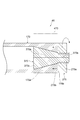
- the end portion 100a of the first member 100 has a cylindrical shape (FRP pipe). Moreover, the edge part 100a of the 1st member 100 is reverse taper shape in the axial direction. Specifically, the end portion 100a of the first member 100 has a shape in which the radial direction (outer diameter) of the outer peripheral surface increases as it approaches the end surface 100b of the first member 100 in the axial direction.
- the reverse taper shape is for fixing the second member to the end portion 100a of the first member 100 as will be described later.
- the end portion 100a of the first member 100 having a reverse taper shape is a portion having a certain length from the end surface 100b in the axial direction.
- the taper angle (angle with respect to the axial direction of the end portion 100a) ⁇ of the end portion 100a is 3 ° to 5 ° in consideration of the fixing strength between the first member 100 and the joining member 300.
- the angle may be 3 °.
- the size in the radial direction (inner diameter) of the inner peripheral surface of the end portion 100a of the first member 100 is constant.
- FIG. 3 shows the arrangement of fibers extending in the axial direction of the first member 100 at the end 100a of the first member 100.
- the arrangement of the fibers at the end 100a of the first member 100 can be, for example, the arrangement shown in the arrangement shown in FIG.
- the plurality of fibers 110a extending substantially in the axial direction of the first member 100 are arranged on the outer side in the radial direction at the end portion 100a of the first member 100.
- the member 100 is provided so that the angle with respect to the axial direction becomes large. That is, as the plurality of fibers 110a are provided closer to the surface forming the reverse tapered shape in the radial direction of the end portion 100a of the first member 100, the angle of the end portion 100a with respect to the axial direction is increased.
- the fiber 110a provided in the axial direction is bent in the same direction as the reverse tapered shape at the boundary 100c with the portion having the reverse tapered shape in the axial direction.
- Each fiber 110a has a larger angle so as to be closer to the taper angle of the end portion 100a as it is provided on the outer side in the radial direction.
- the second member 200 to be joined to the first member 100 has a joint portion 200a that is a portion to be joined to the first member 100.
- the joint portion 200 a has a columnar shape whose outer diameter is approximately the same as the outer diameter of the end surface 100 b of the first member 100.
- the joint portion 200 a has one end surface 200 b that contacts the end surface 100 b of the first member 100.
- the second member 200 has a second member main body 200c formed integrally with the joint portion 200a on the other end face side of the joint portion 200a.
- the second member main body 200c has, for example, a cylindrical shape whose outer diameter is smaller than that of the joint portion 200a.
- the axis of the joint part 200a and the axis of the second member main body 200c are located on the same straight line. Note that the second member main body 200c is not directly related to the bonding structure 10, and can take any shape.
- the axis of the end 100a of the first member 100 and the axis of the joint 200a of the second member 200 are located on the same straight line. Moreover, it is good also as providing the fastening structure conventionally used in the 2nd member 200 side (for example, 2nd member main body 200c part) separately, and enabling joining with another member.
- the joining member 300 is a member that joins the first member 100 and the second member 200 together.
- the joining member 300 is a cylindrical member.
- the joining member 300 is provided in close contact with the reverse tapered shape of the outer peripheral surface of the end portion 100 a of the first member 100 and is connected to the joining portion 200 a of the second member 200.
- the diameter (outer diameter) of the outer peripheral surface of the joining member 300 is larger than the outer diameter of the end portion 100a of the first member 100 and the joining portion 200a of the second member 200, and has the same size in the axial direction. is there.
- the diameter (inner diameter) of the inner peripheral surface of the joining member 300 varies depending on the position in the axial direction as described below.
- the joining member 300 is divided into an adhesion portion 300a that is in close contact with the end portion 100a of the first member 100 in the axial direction, and a connection portion 300b that is connected to the joining portion 200a of the second member 200.
- the length in the axial direction of the contact portion 300a is the same as the length in the axial direction of the portion of the end portion 100a of the first member 100 that has an inversely tapered shape. Further, the inner periphery of the close contact portion 300 a has a shape along the reverse tapered shape of the end portion 100 a of the first member 100. That is, the inner diameter of the end portion of the contact portion 300 a on the connection portion 300 b side is the same as the outer diameter of the end surface 100 b of the first member 100.
- the inner diameter of the end portion on the opening side of the close contact portion 300a is the portion where the reverse taper shape of the end portion 100a of the first member 100 starts (or the reverse taper shape). It is the same size as the outer diameter.
- connection part 300b of the joining member 300 and the outer peripheral surface of the joint part 200a of the second member 200 are connected (fixed) by screwing. That is, the joint portion 200a of the second member 200 is squeezed and fixed to the inner peripheral surface (hole) of the connection portion 300b of the joint member 300. Therefore, a thread groove is provided on the inner peripheral surface of the connection portion 300b, and the diameter (inner diameter) of the inner peripheral surface is the diameter (outer diameter) of the outer peripheral surface of the joint portion 200a of the second member 200. According to the size of the. Further, a thread groove is also provided on the outer peripheral surface of the joint portion 200 a of the second member 200.
- the axial length of the connecting portion 300b is slightly shorter than the axial length of the joint portion 200a.
- the joint portion 200 a is slightly connected. It comes out from the part 300b.
- the joining structure 10 about the part screwed and the part closely_contact
- the second member 200 and the joining member 300 are made of, for example, a metal material (as a metal fitting). For example, it is formed of steel for machine structure, aluminum or the like.
- the contact portion 300a of the joining member 300 and the end portion 100a of the first member 100 are in close contact, and the end surface 200b of the joint portion 200a is in contact with the end surface 100b of the first member 100.
- the connection part 300b of the member 300 and the joint part 200a of the second member 200 By connecting the connection part 300b of the member 300 and the joint part 200a of the second member 200, the end part 100a of the first member 100 and the joint part 200a of the second member 200 are joined. That is, in the joining structure 10 according to the present embodiment, the first member 100 and the second member 200 are joined by using the reverse tapered inclination of the end portion 100a of the first member 100.
- the close contact portion 300a of the joining member 300 has the first member 100 A force F1 from the outer peripheral surface of the end portion 100a is applied. Since the end portion 100a of the first member 100 and the contact portion 300a of the joining member 300 are in close contact with each other with a reverse taper surface, they can withstand a pulling force (tensile load) without concentrating the force in one place. It has a structure.
- the end surface 100b of the first member 100 is applied to the end surface 100b.
- a force F2 from the joint portion 200a of the second member 200 is applied.
- the end surface 100b of the first member 100 and the end surface 200b of the second member 200 on the side of the joint portion 200a are in contact with each other, they can withstand a compressive load.
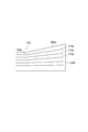
- FIG. 4 shows a graph showing strength characteristics when an oblique tensile force is applied to the unidirectional fiber-reinforced plastic member.
- This graph is shown in Taichi Fujii, Masaru Zako, “Destruction and Mechanics of Composite Materials”, Jikkyo Publishing Co., Ltd., 1989, page 89.
- the graph of the maximum work theory that matches well with the real value shows that the tensile strength is halved at an angle of 5 ° and about 70% at an angle of 5 ° compared to the tensile strength at an angle of 0 °. Become.
- the taper angle of the reverse taper shape of the end portion 100a of the first member 100 may be about 3 ° to 5 ° as described above, and the end portion 100a of the first member 100
- the inclination of the reinforcing fiber to be arranged from the axial direction may be 5 ° or less.
- the compression strength is halved at an angle of 5 °, and about 70% at 3 °.
- the first member 100 made of FRP only needs to have the end portion 100a in a reverse tapered shape. Therefore, it is not necessary to use a special shape that weakens the strength in order to join the first member 100 to the second member 200, and the joining structure 10 is configured while maintaining the strength of the first member 100 itself. be able to.
- the plurality of fibers included in the end portion 100a of the first member 100 are provided so that the angle with respect to the axial direction of the end portion 100a increases as the fiber is provided near the surface forming the reverse tapered shape. Therefore, the strength of the end portion 100a can be ensured. That is, according to the joining structure 10 according to the present embodiment, the joining structure 10 between the first member 100 made of FRP and the other member 200 can be easily and sufficiently, for example, capable of withstanding the compressive load from the joining portion 200a. High bonding strength can be achieved.
- the connecting portion 300b of the joining member 300 and the joining portion 200a of the second member 200 are fixed by screws, but the second portion is connected to the connecting portion 300b of the joining member 300 by other methods.
- the joint 200a of the member 200 may be pushed in and fixed.
- the second member 200 and the joining member 300 are made of metal, but may be made of other materials.
- first member 100 shown in FIG. 2 may be provided with a reinforcing member (stuffing) for supporting the inner peripheral surface in the cylindrical interior 100d of the end portion 100a.
- a reinforcing member for supporting the inner peripheral surface in the cylindrical interior 100d of the end portion 100a.
- the cylindrical end portion 100a may be prevented from being crushed inward in the circumferential direction.
- a hole communicating with the inside of the first member 100 may be provided in the end surface 200b in the second member 200.
- the second member 200 may be cylindrical (tubular), and fluid may flow inside the first member 100 and the second member 200.
- a sealing member such as an O-ring.
- the joining member 300 when the joining member 300 is composed of one member, an end portion on the side opposite to the end portion 100 a of the first member 100 (in the hole provided in the joining member 300 ( The joining member 300 needs to be connected to the end portion 100a of the first member 100 through the first member 100 from the left end portion (not shown in FIG. 2).
- the joining member 300 is cut into two, for example, in a cross section including the axis, and the member cut so as to cover the end portion 100a of the first member 100 in the contact portion 300a is bonded (for example, mechanically connected). Or bonding with an adhesive). This eliminates the need to pass the first member 100 through the hole provided in the joining member 300.
- the joining member 380 may be connected to the first member 180 from the end surface 180b on the side of the end portion 180a having the reverse tapered shape of the first member 180.
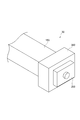
- FIG. 8 is a perspective view of the first member 180.
- FIG. 9A shows an end surface 180b on the end 180a side of the first member 180 having an inversely tapered shape
- FIG. 9B shows close contact with the first member 180 of the joining member 380.
- An end face 380c on the part 380a side is shown.
- the first member 180 is not reversely tapered over the entire outer circumferential surface of the end portion 180a, and only a part of the outer circumferential surface is reversed. Tapered shape. That is, the end portion 180a of the first member 180 has a portion 180d whose outer peripheral surface has a reverse taper shape and a portion 180e whose outer peripheral surface does not have a reverse taper shape in the circumferential direction. Yes.
- three portions 180d having a reverse taper shape are provided at equal intervals in the circumferential direction. Note that the number of the portions 180d provided is not necessarily three, and may be four, for example.
- the portion 180e whose outer peripheral surface is not reversely tapered is sandwiched between the portions 180d that are reversely tapered.
- the portion 180e has an outer diameter that is equal to or smaller than the outer diameter of the reverse tapered shape in the axial direction. More specifically, the outer diameter of the portion 180e is the portion where the reverse taper shape of the end portion 180a of the first member 180 is started (or the portion not having the reverse taper shape inside the end portion 180a). ) Is the same size as the outer diameter.
- the end surface 380c of the joining member 380 is provided with an opening 380f having the same shape as the end surface 100b of the first member 180.
- the end portion 180 a of the first member 180 is inserted into the opening 380 f of the joining member 380. Therefore, the opening 380f may be slightly larger than the shape of the end surface 180b of the first member 180 so that it can be easily inserted.
- the joining member 380 is provided with a groove having a shape of a portion 380d corresponding to the portion 180d of the opening 380f corresponding to the reverse tapered shape of the first member 180 in the axial direction.
- the axial length of the groove is the same as the axial length of the reverse taper shape.
- a portion 380e corresponding to the portion 180e that is not reversely tapered of the first member 180 has the same shape as the contact portion 300a of FIG. That is, the inner periphery of the portion 380e in the axial direction has a shape along the reverse tapered shape of the end portion 180a of the first member 180.
- the first member 180 and the joining member 380 have the above-described configuration, a structure (combined structure) that is fitted to each other can be taken. Specifically, the end 180a of the first member 180 is inserted into the joining member 380 from the opening 380f. After inserting the first member 180 into the joining member 380 by the axial length of the reverse tapered shape, the first member 180 is rotated in the circumferential direction with respect to the joining member 380. Accordingly, the reversely tapered portion 180d of the first member 180 is positioned at a portion 380e where the inner periphery of the bonding member 380 is shaped along the reverse tapered shape. That is, the portions 180d and 380e are in contact with each other as shown in FIG.
- the joining member 380 can be connected to the first member 180 from the end surface 180b on the end portion 180a side which is the inversely tapered shape of the first member 180.
- the first member 180 is a member that is very long in the axial direction, and when it is difficult to connect the joining member 380 from the side opposite to the end portion 180a of the first member 180, the joining member 380 and the first member 180 can be easily connected to each other.
- One member 180 can be connected.
- the first member 100 has the cylindrical shape of the end portion 100a, but it does not necessarily have to be cylindrical.
- the joining structure 20 may be configured by using a columnar member that is not provided with a hollow (hole) therein as the end 150 a of the first member 150.
- the second member 200 and the joining member 300 may be those shown in FIGS.
- the joining structure 30 may be configured using a first member 160, a second member 260, and a joining member 360 having a rectangular cross section. In that case, since the second member 260 and the joining member 360 cannot be connected by screwing, they are connected by any method other than screwing.
- the reverse tapered shape of the end portion 100a of the first member 100 is a shape in which the radial direction (outer diameter) of the outer peripheral surface increases as the end surface 100b of the first member 100 is approached.
- the reverse taper shape may be a shape in which the size of the inner circumferential surface in the radial direction (inner diameter) becomes smaller as it approaches the end surface of the first member.
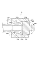
- FIG. 7 shows a cross section of the joining structure 40 in this case.
- the joining structure 40 includes a first member 170, a second member 270, and a joining member 370.
- the end 170a of the first member 170 has a cylindrical shape. Further, the end portion 170a of the first member 170 has a reverse taper shape in the axial direction inside the cylindrical shape. Specifically, the end 170a of the first member 170 has a shape in which the size of the inner circumferential surface in the radial direction (inner diameter) decreases as it approaches the end surface 170b of the first member 170. On the other hand, the radial direction (outer diameter) size of the outer peripheral surface of the end 170a of the first member 170 is constant. Also in the first member 170, the fibers can be oriented in the same manner as shown in FIG.
- the second member 270 to be joined to the first member 170 has a joint portion 270a that is a portion to be joined to the first member 170.
- the joint portion 270 a has a cylindrical shape whose outer diameter is approximately the same as the outer diameter of the end surface 170 b of the first member 170.
- the joint portion 270 a has one end surface 270 b that contacts the end surface 170 b of the first member 170.
- the axis of the end 170 a of the first member 170 and the axis of the joint 270 a of the second member 270 are located on the same straight line.
- the joining member 370 is a member that joins the first member 170 and the second member 270 together.
- the joining member 370 is provided in close contact with the reverse tapered shape of the inner peripheral surface of the end portion 170a of the first member 170 and is connected to the joining portion 270a of the second member 270.
- the joining member 370 is a cylindrical (partially conical) member.
- the diameter (outer diameter) of the outer peripheral surface of the joining member 300 varies depending on the position in the axial direction as described below.
- the joining member 370 is divided into an adhesion portion 370a that is in close contact with the end portion 170a of the first member 170 in the axial direction, and a connection portion 370b that is connected to the joining portion 270a of the second member 270.
- the length of the close contact portion 370a in the axial direction is the same as the length in the axial direction of the portion of the end portion 170a of the first member 170 that has an inversely tapered shape. Further, the inner periphery of the close contact portion 370 a has a shape along the reverse tapered shape of the end portion 170 a of the first member 170. That is, the outer diameter of the end portion of the contact portion 370 a on the connection portion 370 b side is the same as the inner diameter of the end surface 170 b of the first member 170.
- the outer diameter of the other end of the close contact portion 370a is a portion where the reverse taper shape of the end portion 170a of the first member 170 starts (or the reverse taper shape and It is the same size as the inner diameter of the part that is not.
- connection portion 370b of the joining member 370 and the outer peripheral surface of the joint portion 270a of the second member 270 are connected (fixed) by screwing.
- the connection portion 370 b of the bonding member 370 is squeezed and fixed to the inner peripheral surface (hole) of the bonding portion 270 a of the second member 270. Therefore, a thread groove is provided on the outer peripheral surface of the connecting portion 370b, and the diameter (outer diameter) of the outer peripheral surface is equal to the diameter (inner diameter) of the inner peripheral surface of the joint portion 270a of the second member 270. It depends on the size. Further, a screw groove is also provided on the inner peripheral surface of the joint portion 270a of the second member 270.
- the axial length of the connecting portion 370b is slightly longer than the axial length of the joint portion 270a.
- the joint structure 40 using an inversely tapered slope.
- the joint structure 40 using the first member 170 having an inner diameter of about 5 cm and a reverse taper angle of 3 ° can withstand a tensile load of about 10 t.
- size can be comprised.
- the end 170a of the first member 170 has a diameter from the contact portion 370a of the joining member 370. Forces outward in the direction. That is, a force is applied to increase the diameter of the end 170a. Therefore, in order to maintain the bonding strength, a reinforcing member 470 that is wound in the circumferential direction of the outer peripheral surface of the end portion 170a of the first member 170 is provided to prevent the diameter of the end portion 170a of the first member 170 from expanding. Also good.
- fiber reinforced plastic can be appropriately used as a member constituting a structure or the like.
- structures on land and at sea, in the sea, and under the sea (2) buildings, bridges, suspended structures, etc., (3) offshore structures such as floating bodies and platforms, (4) artificial Joints for space-related equipment such as satellite solar panel frames, (5)
- it can be used for medical purposes such as artificial legs.
Abstract
La présente invention permet d'obtenir facilement une résistance d'assemblage suffisante dans une structure d'assemblage entre une matière plastique renforcée de fibres et un autre élément. Un premier élément (100), constitué d'une matière plastique renforcée de fibres et comportant une section d'extrémité en forme de colonne (100a), et un second élément (200), qui est différent du premier élément (100), sont assemblés dans une structure d'assemblage (10). La section d'extrémité (100a) a une forme inversement biseautée dans la direction axiale, et un élément d'assemblage (300) est disposé le long de la forme inversement biseautée de la section d'extrémité (100a). Le second élément (200) est disposé en contact avec la surface d'extrémité du premier élément (100) et est relié à l'élément d'assemblage (300). Une pluralité de fibres (110a) s'étendant dans la direction axiale de la section d'extrémité (100a) sont disposées dans la section d'extrémité (100a) du premier élément (100). Les fibres (110a) sont disposées de sorte que celles situées plus près de la surface constituant la forme inversement biseautée, dans la direction radiale de la section d'extrémité (100a), forment un angle plus grand avec la direction axiale de la section d'extrémité (100a).
Priority Applications (2)
| Application Number | Priority Date | Filing Date | Title |
|---|---|---|---|
| EP14797694.8A EP2998589B1 (fr) | 2013-05-17 | 2014-05-15 | Structure d'assemblage |
| US14/889,371 US10012254B2 (en) | 2013-05-17 | 2014-05-15 | Joining structure |
Applications Claiming Priority (2)
| Application Number | Priority Date | Filing Date | Title |
|---|---|---|---|
| JP2013105070A JP6032848B2 (ja) | 2013-05-17 | 2013-05-17 | 接合構造 |
| JP2013-105070 | 2013-05-17 |
Publications (1)
| Publication Number | Publication Date |
|---|---|
| WO2014185488A1 true WO2014185488A1 (fr) | 2014-11-20 |
Family
ID=51898463
Family Applications (1)
| Application Number | Title | Priority Date | Filing Date |
|---|---|---|---|
| PCT/JP2014/062942 WO2014185488A1 (fr) | 2013-05-17 | 2014-05-15 | Structure d'assemblage |
Country Status (4)
| Country | Link |
|---|---|
| US (1) | US10012254B2 (fr) |
| EP (1) | EP2998589B1 (fr) |
| JP (1) | JP6032848B2 (fr) |
| WO (1) | WO2014185488A1 (fr) |
Cited By (1)
| Publication number | Priority date | Publication date | Assignee | Title |
|---|---|---|---|---|
| JP7390144B2 (ja) | 2019-09-24 | 2023-12-01 | 三菱重工業株式会社 | 複合材の継手部材及び継手構造体 |
Families Citing this family (3)
| Publication number | Priority date | Publication date | Assignee | Title |
|---|---|---|---|---|
| US10781839B2 (en) * | 2016-10-05 | 2020-09-22 | Goodrich Corporation | Hybrid metallic/composite joint with enhanced strength |
| US10927883B2 (en) * | 2017-07-11 | 2021-02-23 | Goodrich Corporation | Composite joint assembly |
| US10823213B2 (en) * | 2018-06-08 | 2020-11-03 | Goodrich Corporation | Composite joint assembly |
Citations (7)
| Publication number | Priority date | Publication date | Assignee | Title |
|---|---|---|---|---|
| JPS503118B1 (fr) * | 1969-06-20 | 1975-01-31 | ||
| JPS55159121U (fr) * | 1979-05-04 | 1980-11-15 | ||
| JPS6038573U (ja) * | 1983-08-26 | 1985-03-16 | ダイワ精工株式会社 | 釣竿 |
| JPS62132010A (ja) * | 1985-12-03 | 1987-06-15 | 株式会社東芝 | 支持材の製造方法 |
| JPS6487231A (en) * | 1987-09-30 | 1989-03-31 | Toshiba Corp | Fiber reinforced plastic support bar |
| JPH0350592A (ja) | 1989-07-19 | 1991-03-05 | Hitachi Ltd | 投写型画像ディスプレイ装置及びそのレンズ |
| JPH06170958A (ja) * | 1992-12-11 | 1994-06-21 | Ichinomiya Orimono:Kk | 円錐形回転体の製造方法 |
Family Cites Families (22)
| Publication number | Priority date | Publication date | Assignee | Title |
|---|---|---|---|---|
| US3374511A (en) * | 1966-01-10 | 1968-03-26 | Cable Cover Ltd | Cable grip |
| GB1209891A (en) * | 1966-08-10 | 1970-10-21 | Permali Ltd | Stay member and end fitting |
| US3858992A (en) * | 1971-10-07 | 1975-01-07 | Preformed Line Products Co | Strain relief coupling |
| US3960459A (en) * | 1972-03-30 | 1976-06-01 | The United States Of America As Represented By The Secretary Of The Navy | Reduced shear stress end fitting |
| US4899499A (en) * | 1987-04-30 | 1990-02-13 | Hoekstra Charles F | Cable anchoring apparatus |
| US5015023A (en) * | 1989-12-11 | 1991-05-14 | Hall Gaddis G | Automatic cable gripping device |
| US5369849A (en) * | 1993-03-25 | 1994-12-06 | Fargo Mfg. Company, Inc. | Cable gripping unit with spring biased jaw segments |
| US5594977A (en) * | 1993-12-30 | 1997-01-21 | Mccallion; James P. | Smooth rod-gripping apparatus |
| US5683273A (en) * | 1996-07-24 | 1997-11-04 | The Whitaker Corporation | Mechanical splice connector for cable |
| JPH11350592A (ja) | 1998-06-11 | 1999-12-21 | Ohbayashi Corp | トラス部材の接合構造 |
| US20040097144A1 (en) * | 2002-11-13 | 2004-05-20 | Campbell Richard Vest | Anti-back-out cable termination devices |
| AU2003271451A1 (en) * | 2003-10-03 | 2005-04-21 | University Of Waterloo | Tension anchorage system |
| US7543360B2 (en) * | 2004-09-21 | 2009-06-09 | Bright Technologies, Llc. | Flex accommodating cable terminations |
| US7367090B2 (en) * | 2005-07-08 | 2008-05-06 | Harnischfeger Technologies, Inc. | Fitting for wire rope |
| US20070006429A1 (en) * | 2005-07-08 | 2007-01-11 | Harnischfeger Technologies, Inc. | Fitting for wire rope |
| US20080282511A1 (en) | 2007-05-19 | 2008-11-20 | Chia-Te Chou | Composite rope structures and systems and methods for terminating composite rope structures |
| US20090205172A1 (en) * | 2008-02-19 | 2009-08-20 | Campbell Richard V | Cable termination with an elliptical wall profile |
| US8286309B2 (en) * | 2008-06-10 | 2012-10-16 | Actuant Corporation | Median barrier cable termination |
| US8215886B2 (en) * | 2008-10-24 | 2012-07-10 | Campbell Richard V | Coupler bolt termination system |
| US8607881B2 (en) * | 2010-12-08 | 2013-12-17 | National Oilwell Varco, L.P. | Heavy duty rope sockets and related methods |
| JP5954703B2 (ja) * | 2012-03-30 | 2016-07-20 | 国立研究開発法人海洋研究開発機構 | 圧力容器 |
| TWI502117B (zh) * | 2012-10-24 | 2015-10-01 | Su-I Lim | 續接器 |
-
2013
- 2013-05-17 JP JP2013105070A patent/JP6032848B2/ja not_active Expired - Fee Related
-
2014
- 2014-05-15 EP EP14797694.8A patent/EP2998589B1/fr active Active
- 2014-05-15 WO PCT/JP2014/062942 patent/WO2014185488A1/fr active Application Filing
- 2014-05-15 US US14/889,371 patent/US10012254B2/en not_active Expired - Fee Related
Patent Citations (7)
| Publication number | Priority date | Publication date | Assignee | Title |
|---|---|---|---|---|
| JPS503118B1 (fr) * | 1969-06-20 | 1975-01-31 | ||
| JPS55159121U (fr) * | 1979-05-04 | 1980-11-15 | ||
| JPS6038573U (ja) * | 1983-08-26 | 1985-03-16 | ダイワ精工株式会社 | 釣竿 |
| JPS62132010A (ja) * | 1985-12-03 | 1987-06-15 | 株式会社東芝 | 支持材の製造方法 |
| JPS6487231A (en) * | 1987-09-30 | 1989-03-31 | Toshiba Corp | Fiber reinforced plastic support bar |
| JPH0350592A (ja) | 1989-07-19 | 1991-03-05 | Hitachi Ltd | 投写型画像ディスプレイ装置及びそのレンズ |
| JPH06170958A (ja) * | 1992-12-11 | 1994-06-21 | Ichinomiya Orimono:Kk | 円錐形回転体の製造方法 |
Non-Patent Citations (2)
| Title |
|---|
| FUJII TAICHI; ZAKO MASARU: "Fracture and Mechanics of Composite Materials", 1978, JIKKYO SHUPPAN, CO., LTD., pages: 89 |
| See also references of EP2998589A4 |
Cited By (1)
| Publication number | Priority date | Publication date | Assignee | Title |
|---|---|---|---|---|
| JP7390144B2 (ja) | 2019-09-24 | 2023-12-01 | 三菱重工業株式会社 | 複合材の継手部材及び継手構造体 |
Also Published As
| Publication number | Publication date |
|---|---|
| EP2998589A1 (fr) | 2016-03-23 |
| EP2998589B1 (fr) | 2023-04-19 |
| JP2014224431A (ja) | 2014-12-04 |
| JP6032848B2 (ja) | 2016-11-30 |
| US20160076569A1 (en) | 2016-03-17 |
| EP2998589A4 (fr) | 2017-01-25 |
| US10012254B2 (en) | 2018-07-03 |
Similar Documents
| Publication | Publication Date | Title |
|---|---|---|
| WO2014185488A1 (fr) | Structure d'assemblage | |
| US4205927A (en) | Flanged joint structure for composite materials | |
| JP4673917B2 (ja) | 航空機の空調用空気管路 | |
| ES2385906B1 (es) | Disposición de unión circunferencial de elementos estructurales con un elemento de acoplamiento realizado en material compuesto. | |
| US10184509B2 (en) | Composite tension/compression strut | |
| US20170184232A1 (en) | Method For Connecting A Coupling Device To Respective Ends Of Two Pipes, And Structure Of Said Coupling Device | |
| JP2016528063A (ja) | 接続ロッド、それを製造する方法、及びそれを含む航空機用の床構造体 | |
| US20150071701A1 (en) | Insert and Method of Attaching Insert to Structure | |
| BR102018071189A2 (pt) | Estrutura tubular compósita, e, métodos de fabricação da estrutura tubular e de melhoria da força compressiva de uma conexão. | |
| US10532518B2 (en) | Hybrid metallic/composite joint with enhanced performance | |
| US20200378423A1 (en) | Hybrid metallic/composite joint with enhanced strength | |
| JP5837628B2 (ja) | 繊維強化プラスチック製曲管 | |
| JP3155761U (ja) | 絶縁ボルト構造および配管連結構造 | |
| WO2016130021A3 (fr) | Raccord fileté | |
| US10131417B2 (en) | Hybrid carbon/fiberglass structural component for an aircraft | |
| RU2607575C2 (ru) | Секционная оболочка для внутреннего давления из слоистого композиционного материала | |
| US9803672B2 (en) | Split end tube connector | |
| CA2692286A1 (fr) | Connexions pour elements tubulaires extensibles | |
| RU2633897C1 (ru) | Узловое сборно-разборное соединение деревянных стержней | |
| JP5597614B2 (ja) | ブレース構造 | |
| JP2018189212A (ja) | Frp製部材の接合構造 | |
| JPH0529192Y2 (fr) | ||
| RU2418999C1 (ru) | Способ соединения деталей | |
| JPH0135050Y2 (fr) | ||
| WO2022066056A1 (fr) | Unité de connexion de poutres en bois |
Legal Events
| Date | Code | Title | Description |
|---|---|---|---|
| 121 | Ep: the epo has been informed by wipo that ep was designated in this application |
Ref document number: 14797694 Country of ref document: EP Kind code of ref document: A1 |
|
| WWE | Wipo information: entry into national phase |
Ref document number: 14889371 Country of ref document: US |
|
| WWE | Wipo information: entry into national phase |
Ref document number: 2014797694 Country of ref document: EP |
|
| NENP | Non-entry into the national phase |
Ref country code: DE |