WO2014185488A1 - Joining structure - Google Patents
Joining structure Download PDFInfo
- Publication number
- WO2014185488A1 WO2014185488A1 PCT/JP2014/062942 JP2014062942W WO2014185488A1 WO 2014185488 A1 WO2014185488 A1 WO 2014185488A1 JP 2014062942 W JP2014062942 W JP 2014062942W WO 2014185488 A1 WO2014185488 A1 WO 2014185488A1
- Authority
- WO
- WIPO (PCT)
- Prior art keywords
- joining
- end portion
- tapered shape
- shape
- axial direction
- Prior art date
Links
- 239000000835 fiber Substances 0.000 claims abstract description 25
- 239000011151 fibre-reinforced plastic Substances 0.000 claims abstract description 16
- 229920002430 Fibre-reinforced plastic Polymers 0.000 claims abstract description 15
- 230000002093 peripheral effect Effects 0.000 claims description 40
- 230000003014 reinforcing effect Effects 0.000 claims description 7
- 229910052751 metal Inorganic materials 0.000 claims description 6
- 239000002184 metal Substances 0.000 claims description 6
- 238000013459 approach Methods 0.000 claims description 4
- 239000004918 carbon fiber reinforced polymer Substances 0.000 claims description 4
- 230000007423 decrease Effects 0.000 claims description 3
- 230000004323 axial length Effects 0.000 description 7
- 239000000853 adhesive Substances 0.000 description 5
- 238000012986 modification Methods 0.000 description 5
- 230000004048 modification Effects 0.000 description 5
- 230000001070 adhesive effect Effects 0.000 description 4
- 229920006231 aramid fiber Polymers 0.000 description 2
- 239000012530 fluid Substances 0.000 description 2
- 239000007769 metal material Substances 0.000 description 2
- 238000000034 method Methods 0.000 description 2
- 229910000831 Steel Inorganic materials 0.000 description 1
- 229910052782 aluminium Inorganic materials 0.000 description 1
- XAGFODPZIPBFFR-UHFFFAOYSA-N aluminium Chemical compound [Al] XAGFODPZIPBFFR-UHFFFAOYSA-N 0.000 description 1
- 239000002131 composite material Substances 0.000 description 1
- 230000006835 compression Effects 0.000 description 1
- 238000007906 compression Methods 0.000 description 1
- 230000006378 damage Effects 0.000 description 1
- 239000011152 fibreglass Substances 0.000 description 1
- 239000011521 glass Substances 0.000 description 1
- 239000000463 material Substances 0.000 description 1
- 230000000704 physical effect Effects 0.000 description 1
- 229920003023 plastic Polymers 0.000 description 1
- 239000004033 plastic Substances 0.000 description 1
- 239000012783 reinforcing fiber Substances 0.000 description 1
- 238000007789 sealing Methods 0.000 description 1
- 239000010959 steel Substances 0.000 description 1
Images


Classifications
-
- F—MECHANICAL ENGINEERING; LIGHTING; HEATING; WEAPONS; BLASTING
- F16—ENGINEERING ELEMENTS AND UNITS; GENERAL MEASURES FOR PRODUCING AND MAINTAINING EFFECTIVE FUNCTIONING OF MACHINES OR INSTALLATIONS; THERMAL INSULATION IN GENERAL
- F16B—DEVICES FOR FASTENING OR SECURING CONSTRUCTIONAL ELEMENTS OR MACHINE PARTS TOGETHER, e.g. NAILS, BOLTS, CIRCLIPS, CLAMPS, CLIPS OR WEDGES; JOINTS OR JOINTING
- F16B7/00—Connections of rods or tubes, e.g. of non-circular section, mutually, including resilient connections
- F16B7/02—Connections of rods or tubes, e.g. of non-circular section, mutually, including resilient connections with conical parts
-
- B—PERFORMING OPERATIONS; TRANSPORTING
- B29—WORKING OF PLASTICS; WORKING OF SUBSTANCES IN A PLASTIC STATE IN GENERAL
- B29C—SHAPING OR JOINING OF PLASTICS; SHAPING OF MATERIAL IN A PLASTIC STATE, NOT OTHERWISE PROVIDED FOR; AFTER-TREATMENT OF THE SHAPED PRODUCTS, e.g. REPAIRING
- B29C65/00—Joining or sealing of preformed parts, e.g. welding of plastics materials; Apparatus therefor
- B29C65/56—Joining or sealing of preformed parts, e.g. welding of plastics materials; Apparatus therefor using mechanical means or mechanical connections, e.g. form-fits
- B29C65/561—Joining or sealing of preformed parts, e.g. welding of plastics materials; Apparatus therefor using mechanical means or mechanical connections, e.g. form-fits using screw-threads being integral at least to one of the parts to be joined
-
- B—PERFORMING OPERATIONS; TRANSPORTING
- B29—WORKING OF PLASTICS; WORKING OF SUBSTANCES IN A PLASTIC STATE IN GENERAL
- B29C—SHAPING OR JOINING OF PLASTICS; SHAPING OF MATERIAL IN A PLASTIC STATE, NOT OTHERWISE PROVIDED FOR; AFTER-TREATMENT OF THE SHAPED PRODUCTS, e.g. REPAIRING
- B29C65/00—Joining or sealing of preformed parts, e.g. welding of plastics materials; Apparatus therefor
- B29C65/56—Joining or sealing of preformed parts, e.g. welding of plastics materials; Apparatus therefor using mechanical means or mechanical connections, e.g. form-fits
- B29C65/562—Joining or sealing of preformed parts, e.g. welding of plastics materials; Apparatus therefor using mechanical means or mechanical connections, e.g. form-fits using extra joining elements, i.e. which are not integral with the parts to be joined
-
- B—PERFORMING OPERATIONS; TRANSPORTING
- B29—WORKING OF PLASTICS; WORKING OF SUBSTANCES IN A PLASTIC STATE IN GENERAL
- B29C—SHAPING OR JOINING OF PLASTICS; SHAPING OF MATERIAL IN A PLASTIC STATE, NOT OTHERWISE PROVIDED FOR; AFTER-TREATMENT OF THE SHAPED PRODUCTS, e.g. REPAIRING
- B29C66/00—General aspects of processes or apparatus for joining preformed parts
- B29C66/01—General aspects dealing with the joint area or with the area to be joined
- B29C66/05—Particular design of joint configurations
- B29C66/10—Particular design of joint configurations particular design of the joint cross-sections
- B29C66/11—Joint cross-sections comprising a single joint-segment, i.e. one of the parts to be joined comprising a single joint-segment in the joint cross-section
- B29C66/114—Single butt joints
- B29C66/1142—Single butt to butt joints
-
- B—PERFORMING OPERATIONS; TRANSPORTING
- B29—WORKING OF PLASTICS; WORKING OF SUBSTANCES IN A PLASTIC STATE IN GENERAL
- B29C—SHAPING OR JOINING OF PLASTICS; SHAPING OF MATERIAL IN A PLASTIC STATE, NOT OTHERWISE PROVIDED FOR; AFTER-TREATMENT OF THE SHAPED PRODUCTS, e.g. REPAIRING
- B29C66/00—General aspects of processes or apparatus for joining preformed parts
- B29C66/50—General aspects of joining tubular articles; General aspects of joining long products, i.e. bars or profiled elements; General aspects of joining single elements to tubular articles, hollow articles or bars; General aspects of joining several hollow-preforms to form hollow or tubular articles
- B29C66/51—Joining tubular articles, profiled elements or bars; Joining single elements to tubular articles, hollow articles or bars; Joining several hollow-preforms to form hollow or tubular articles
- B29C66/52—Joining tubular articles, bars or profiled elements
- B29C66/522—Joining tubular articles
-
- B—PERFORMING OPERATIONS; TRANSPORTING
- B29—WORKING OF PLASTICS; WORKING OF SUBSTANCES IN A PLASTIC STATE IN GENERAL
- B29C—SHAPING OR JOINING OF PLASTICS; SHAPING OF MATERIAL IN A PLASTIC STATE, NOT OTHERWISE PROVIDED FOR; AFTER-TREATMENT OF THE SHAPED PRODUCTS, e.g. REPAIRING
- B29C66/00—General aspects of processes or apparatus for joining preformed parts
- B29C66/50—General aspects of joining tubular articles; General aspects of joining long products, i.e. bars or profiled elements; General aspects of joining single elements to tubular articles, hollow articles or bars; General aspects of joining several hollow-preforms to form hollow or tubular articles
- B29C66/51—Joining tubular articles, profiled elements or bars; Joining single elements to tubular articles, hollow articles or bars; Joining several hollow-preforms to form hollow or tubular articles
- B29C66/52—Joining tubular articles, bars or profiled elements
- B29C66/524—Joining profiled elements
-
- B—PERFORMING OPERATIONS; TRANSPORTING
- B29—WORKING OF PLASTICS; WORKING OF SUBSTANCES IN A PLASTIC STATE IN GENERAL
- B29C—SHAPING OR JOINING OF PLASTICS; SHAPING OF MATERIAL IN A PLASTIC STATE, NOT OTHERWISE PROVIDED FOR; AFTER-TREATMENT OF THE SHAPED PRODUCTS, e.g. REPAIRING
- B29C66/00—General aspects of processes or apparatus for joining preformed parts
- B29C66/50—General aspects of joining tubular articles; General aspects of joining long products, i.e. bars or profiled elements; General aspects of joining single elements to tubular articles, hollow articles or bars; General aspects of joining several hollow-preforms to form hollow or tubular articles
- B29C66/51—Joining tubular articles, profiled elements or bars; Joining single elements to tubular articles, hollow articles or bars; Joining several hollow-preforms to form hollow or tubular articles
- B29C66/52—Joining tubular articles, bars or profiled elements
- B29C66/526—Joining bars
-
- B—PERFORMING OPERATIONS; TRANSPORTING
- B29—WORKING OF PLASTICS; WORKING OF SUBSTANCES IN A PLASTIC STATE IN GENERAL
- B29C—SHAPING OR JOINING OF PLASTICS; SHAPING OF MATERIAL IN A PLASTIC STATE, NOT OTHERWISE PROVIDED FOR; AFTER-TREATMENT OF THE SHAPED PRODUCTS, e.g. REPAIRING
- B29C66/00—General aspects of processes or apparatus for joining preformed parts
- B29C66/50—General aspects of joining tubular articles; General aspects of joining long products, i.e. bars or profiled elements; General aspects of joining single elements to tubular articles, hollow articles or bars; General aspects of joining several hollow-preforms to form hollow or tubular articles
- B29C66/51—Joining tubular articles, profiled elements or bars; Joining single elements to tubular articles, hollow articles or bars; Joining several hollow-preforms to form hollow or tubular articles
- B29C66/53—Joining single elements to tubular articles, hollow articles or bars
- B29C66/534—Joining single elements to open ends of tubular or hollow articles or to the ends of bars
- B29C66/5344—Joining single elements to open ends of tubular or hollow articles or to the ends of bars said single elements being substantially annular, i.e. of finite length, e.g. joining flanges to tube ends
-
- B—PERFORMING OPERATIONS; TRANSPORTING
- B29—WORKING OF PLASTICS; WORKING OF SUBSTANCES IN A PLASTIC STATE IN GENERAL
- B29C—SHAPING OR JOINING OF PLASTICS; SHAPING OF MATERIAL IN A PLASTIC STATE, NOT OTHERWISE PROVIDED FOR; AFTER-TREATMENT OF THE SHAPED PRODUCTS, e.g. REPAIRING
- B29C66/00—General aspects of processes or apparatus for joining preformed parts
- B29C66/70—General aspects of processes or apparatus for joining preformed parts characterised by the composition, physical properties or the structure of the material of the parts to be joined; Joining with non-plastics material
- B29C66/72—General aspects of processes or apparatus for joining preformed parts characterised by the composition, physical properties or the structure of the material of the parts to be joined; Joining with non-plastics material characterised by the structure of the material of the parts to be joined
- B29C66/721—Fibre-reinforced materials
- B29C66/7214—Fibre-reinforced materials characterised by the length of the fibres
- B29C66/72141—Fibres of continuous length
-
- B—PERFORMING OPERATIONS; TRANSPORTING
- B29—WORKING OF PLASTICS; WORKING OF SUBSTANCES IN A PLASTIC STATE IN GENERAL
- B29C—SHAPING OR JOINING OF PLASTICS; SHAPING OF MATERIAL IN A PLASTIC STATE, NOT OTHERWISE PROVIDED FOR; AFTER-TREATMENT OF THE SHAPED PRODUCTS, e.g. REPAIRING
- B29C66/00—General aspects of processes or apparatus for joining preformed parts
- B29C66/70—General aspects of processes or apparatus for joining preformed parts characterised by the composition, physical properties or the structure of the material of the parts to be joined; Joining with non-plastics material
- B29C66/74—Joining plastics material to non-plastics material
- B29C66/742—Joining plastics material to non-plastics material to metals or their alloys
-
- B—PERFORMING OPERATIONS; TRANSPORTING
- B29—WORKING OF PLASTICS; WORKING OF SUBSTANCES IN A PLASTIC STATE IN GENERAL
- B29C—SHAPING OR JOINING OF PLASTICS; SHAPING OF MATERIAL IN A PLASTIC STATE, NOT OTHERWISE PROVIDED FOR; AFTER-TREATMENT OF THE SHAPED PRODUCTS, e.g. REPAIRING
- B29C66/00—General aspects of processes or apparatus for joining preformed parts
- B29C66/70—General aspects of processes or apparatus for joining preformed parts characterised by the composition, physical properties or the structure of the material of the parts to be joined; Joining with non-plastics material
- B29C66/72—General aspects of processes or apparatus for joining preformed parts characterised by the composition, physical properties or the structure of the material of the parts to be joined; Joining with non-plastics material characterised by the structure of the material of the parts to be joined
- B29C66/721—Fibre-reinforced materials
- B29C66/7212—Fibre-reinforced materials characterised by the composition of the fibres
-
- B—PERFORMING OPERATIONS; TRANSPORTING
- B29—WORKING OF PLASTICS; WORKING OF SUBSTANCES IN A PLASTIC STATE IN GENERAL
- B29K—INDEXING SCHEME ASSOCIATED WITH SUBCLASSES B29B, B29C OR B29D, RELATING TO MOULDING MATERIALS OR TO MATERIALS FOR MOULDS, REINFORCEMENTS, FILLERS OR PREFORMED PARTS, e.g. INSERTS
- B29K2101/00—Use of unspecified macromolecular compounds as moulding material
-
- B—PERFORMING OPERATIONS; TRANSPORTING
- B29—WORKING OF PLASTICS; WORKING OF SUBSTANCES IN A PLASTIC STATE IN GENERAL
- B29K—INDEXING SCHEME ASSOCIATED WITH SUBCLASSES B29B, B29C OR B29D, RELATING TO MOULDING MATERIALS OR TO MATERIALS FOR MOULDS, REINFORCEMENTS, FILLERS OR PREFORMED PARTS, e.g. INSERTS
- B29K2105/00—Condition, form or state of moulded material or of the material to be shaped
- B29K2105/06—Condition, form or state of moulded material or of the material to be shaped containing reinforcements, fillers or inserts
- B29K2105/12—Condition, form or state of moulded material or of the material to be shaped containing reinforcements, fillers or inserts of short lengths, e.g. chopped filaments, staple fibres or bristles
-
- B—PERFORMING OPERATIONS; TRANSPORTING
- B29—WORKING OF PLASTICS; WORKING OF SUBSTANCES IN A PLASTIC STATE IN GENERAL
- B29K—INDEXING SCHEME ASSOCIATED WITH SUBCLASSES B29B, B29C OR B29D, RELATING TO MOULDING MATERIALS OR TO MATERIALS FOR MOULDS, REINFORCEMENTS, FILLERS OR PREFORMED PARTS, e.g. INSERTS
- B29K2307/00—Use of elements other than metals as reinforcement
- B29K2307/04—Carbon
-
- B—PERFORMING OPERATIONS; TRANSPORTING
- B29—WORKING OF PLASTICS; WORKING OF SUBSTANCES IN A PLASTIC STATE IN GENERAL
- B29L—INDEXING SCHEME ASSOCIATED WITH SUBCLASS B29C, RELATING TO PARTICULAR ARTICLES
- B29L2023/00—Tubular articles
- B29L2023/22—Tubes or pipes, i.e. rigid
-
- B—PERFORMING OPERATIONS; TRANSPORTING
- B29—WORKING OF PLASTICS; WORKING OF SUBSTANCES IN A PLASTIC STATE IN GENERAL
- B29L—INDEXING SCHEME ASSOCIATED WITH SUBCLASS B29C, RELATING TO PARTICULAR ARTICLES
- B29L2031/00—Other particular articles
- B29L2031/30—Vehicles, e.g. ships or aircraft, or body parts thereof
- B29L2031/3002—Superstructures characterized by combining metal and plastics, i.e. hybrid parts
-
- B—PERFORMING OPERATIONS; TRANSPORTING
- B29—WORKING OF PLASTICS; WORKING OF SUBSTANCES IN A PLASTIC STATE IN GENERAL
- B29L—INDEXING SCHEME ASSOCIATED WITH SUBCLASS B29C, RELATING TO PARTICULAR ARTICLES
- B29L2031/00—Other particular articles
- B29L2031/753—Medical equipment; Accessories therefor
- B29L2031/7532—Artificial members, protheses
Definitions
- the present invention relates to a joint structure between a member made of fiber reinforced plastic and another member.
- a bonding structure by bonding such as applying an adhesive to the bonding surface between the FRP and the metal and sticking it can be considered.
- dirt on the bonding surface, moisture, and the like affect the bonding strength.
- the thickness of the adhesive affects the bonding strength.
- the physical properties of the adhesive may change due to temperature or the like.
- the bonding structure by bonding has a problem that there are many factors that affect the bonding strength, and it is difficult to manage them.
- the present invention has been made in view of the above problems, and an object of the present invention is to provide a joint structure that can easily achieve sufficient joint strength in a joint structure between a fiber-reinforced plastic and another member. To do.
- a joining structure includes a first member having a columnar end made of fiber-reinforced plastic and a second member different from the first member.
- the end portion of the first member has an inversely tapered shape in the axial direction, and includes a joining member provided along the inversely tapered shape of the end portion of the first member.
- the member is provided in contact with the end surface of the first member and is connected to the joining member, and a plurality of fibers extending substantially in the axial direction of the end portion inside the end portion of the first member
- the plurality of fibers have a larger angle with respect to the axial direction of the end portion as the fiber is provided near the surface constituting the reverse tapered shape in the radial direction of the end portion of the first member. It is provided to become.
- the joining structure which concerns on one Embodiment of this invention is what joined the 1st member and the 2nd member using the reverse taper-shaped inclination of the edge part of the 1st member which consists of fiber reinforced plastics.
- the first member made of fiber reinforced plastic only needs to have a reverse tapered shape at the end, and the strength of the first member itself is maintained.
- the junction structure can be configured as it is.
- the plurality of fibers included in the end portion of the first member are provided so that the angle with respect to the axial direction of the end portion increases as the fiber is provided near the surface forming the inversely tapered shape. Therefore, the strength of the end can be ensured. That is, according to the joint structure according to an embodiment of the present invention, sufficient joint strength can be easily achieved in the joint structure between the fiber reinforced plastic and another member.
- the reverse tapered shape may be a shape in which the radial size of the outer peripheral surface increases as the end surface of the first member is approached. According to this configuration, the first member can be configured reliably and easily.
- the end of the first member has a portion whose outer diameter is equal to or smaller than the outer diameter of the reverse tapered shape in a part of the circumferential direction of the portion that is the reverse tapered shape on the outer peripheral surface,
- the first member and the joining member may be fitted together. According to this configuration, the joining member can be connected to the first member from the end surface on the end side that is the inversely tapered shape of the first member.
- the end portion of the first member may be cylindrical, and a reinforcing member that supports the inner peripheral surface may be provided inside the end portion of the cylindrical first member. According to this structure, it can prevent that the edge part of a cylindrical 1st member is crushed inside.
- the end portion of the first member is cylindrical, and the reverse tapered shape is a shape in which the radial size of the inner peripheral surface decreases as the end surface of the first member is approached.
- the member may be provided inside the end portion of the cylindrical first member.
- a reinforcing member wound around the outer peripheral surface of the end portion of the cylindrical first member may be provided. According to this configuration, the bonding strength can be further increased.
- the angle with respect to the axial direction of the end portion of the first member having the inversely tapered shape may be any of 3 ° to 5 °. According to this configuration, it is possible to increase the bonding strength between the first member and the second member at the end portion of the inversely tapered shape of the first member.
- the first member may be made of carbon fiber reinforced plastic.
- the other second member may be made of metal.
- sufficient joint strength can be easily achieved in a joint structure between a fiber reinforced plastic and another member.
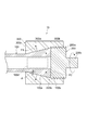
- FIG. 1 shows a perspective view of a joining structure 10 according to the present embodiment.
- the joining structure 10 is a structure that joins a first member 100 having a columnar end and a second member 200 configured as a separate body from the first member.
- the columnar shape includes a cylindrical shape having an outer peripheral surface and similar to the columnar shape on the side surface.
- the joining structure 10 includes a joining member 300 that joins the first member 100 and the second member 200 together.
- the first member 100 is a member made of FRP.
- the joint structure 10 according to the present embodiment is for joining the first member 100 made of, for example, FRP with another member in order to use it as a member constituting the structure.
- FRP configuring the first member 100 for example, CRFP (Carbon Fiber Reinforced Plastics, carbon fiber reinforced plastic) is used.
- CRFP Carbon Fiber Reinforced Plastics, carbon fiber reinforced plastic
- GRFP Glass FiberforceReinforced Plastics, glass fiber reinforced plastic
- AFRP Automatic Fiber Reinforced Plastics, aramid fiber reinforced plastic
- fibers can be oriented in the two directions of the axial direction and the circumferential direction at the end portion 100a of the first member 100. Thereby, the intensity
- the end portion 100a of the first member 100 has a cylindrical shape (FRP pipe). Moreover, the edge part 100a of the 1st member 100 is reverse taper shape in the axial direction. Specifically, the end portion 100a of the first member 100 has a shape in which the radial direction (outer diameter) of the outer peripheral surface increases as it approaches the end surface 100b of the first member 100 in the axial direction.
- the reverse taper shape is for fixing the second member to the end portion 100a of the first member 100 as will be described later.
- the end portion 100a of the first member 100 having a reverse taper shape is a portion having a certain length from the end surface 100b in the axial direction.
- the taper angle (angle with respect to the axial direction of the end portion 100a) ⁇ of the end portion 100a is 3 ° to 5 ° in consideration of the fixing strength between the first member 100 and the joining member 300.
- the angle may be 3 °.
- the size in the radial direction (inner diameter) of the inner peripheral surface of the end portion 100a of the first member 100 is constant.
- FIG. 3 shows the arrangement of fibers extending in the axial direction of the first member 100 at the end 100a of the first member 100.
- the arrangement of the fibers at the end 100a of the first member 100 can be, for example, the arrangement shown in the arrangement shown in FIG.
- the plurality of fibers 110a extending substantially in the axial direction of the first member 100 are arranged on the outer side in the radial direction at the end portion 100a of the first member 100.
- the member 100 is provided so that the angle with respect to the axial direction becomes large. That is, as the plurality of fibers 110a are provided closer to the surface forming the reverse tapered shape in the radial direction of the end portion 100a of the first member 100, the angle of the end portion 100a with respect to the axial direction is increased.
- the fiber 110a provided in the axial direction is bent in the same direction as the reverse tapered shape at the boundary 100c with the portion having the reverse tapered shape in the axial direction.
- Each fiber 110a has a larger angle so as to be closer to the taper angle of the end portion 100a as it is provided on the outer side in the radial direction.
- the second member 200 to be joined to the first member 100 has a joint portion 200a that is a portion to be joined to the first member 100.
- the joint portion 200 a has a columnar shape whose outer diameter is approximately the same as the outer diameter of the end surface 100 b of the first member 100.
- the joint portion 200 a has one end surface 200 b that contacts the end surface 100 b of the first member 100.
- the second member 200 has a second member main body 200c formed integrally with the joint portion 200a on the other end face side of the joint portion 200a.
- the second member main body 200c has, for example, a cylindrical shape whose outer diameter is smaller than that of the joint portion 200a.
- the axis of the joint part 200a and the axis of the second member main body 200c are located on the same straight line. Note that the second member main body 200c is not directly related to the bonding structure 10, and can take any shape.
- the axis of the end 100a of the first member 100 and the axis of the joint 200a of the second member 200 are located on the same straight line. Moreover, it is good also as providing the fastening structure conventionally used in the 2nd member 200 side (for example, 2nd member main body 200c part) separately, and enabling joining with another member.
- the joining member 300 is a member that joins the first member 100 and the second member 200 together.
- the joining member 300 is a cylindrical member.
- the joining member 300 is provided in close contact with the reverse tapered shape of the outer peripheral surface of the end portion 100 a of the first member 100 and is connected to the joining portion 200 a of the second member 200.
- the diameter (outer diameter) of the outer peripheral surface of the joining member 300 is larger than the outer diameter of the end portion 100a of the first member 100 and the joining portion 200a of the second member 200, and has the same size in the axial direction. is there.
- the diameter (inner diameter) of the inner peripheral surface of the joining member 300 varies depending on the position in the axial direction as described below.
- the joining member 300 is divided into an adhesion portion 300a that is in close contact with the end portion 100a of the first member 100 in the axial direction, and a connection portion 300b that is connected to the joining portion 200a of the second member 200.
- the length in the axial direction of the contact portion 300a is the same as the length in the axial direction of the portion of the end portion 100a of the first member 100 that has an inversely tapered shape. Further, the inner periphery of the close contact portion 300 a has a shape along the reverse tapered shape of the end portion 100 a of the first member 100. That is, the inner diameter of the end portion of the contact portion 300 a on the connection portion 300 b side is the same as the outer diameter of the end surface 100 b of the first member 100.
- the inner diameter of the end portion on the opening side of the close contact portion 300a is the portion where the reverse taper shape of the end portion 100a of the first member 100 starts (or the reverse taper shape). It is the same size as the outer diameter.
- connection part 300b of the joining member 300 and the outer peripheral surface of the joint part 200a of the second member 200 are connected (fixed) by screwing. That is, the joint portion 200a of the second member 200 is squeezed and fixed to the inner peripheral surface (hole) of the connection portion 300b of the joint member 300. Therefore, a thread groove is provided on the inner peripheral surface of the connection portion 300b, and the diameter (inner diameter) of the inner peripheral surface is the diameter (outer diameter) of the outer peripheral surface of the joint portion 200a of the second member 200. According to the size of the. Further, a thread groove is also provided on the outer peripheral surface of the joint portion 200 a of the second member 200.
- the axial length of the connecting portion 300b is slightly shorter than the axial length of the joint portion 200a.
- the joint portion 200 a is slightly connected. It comes out from the part 300b.
- the joining structure 10 about the part screwed and the part closely_contact
- the second member 200 and the joining member 300 are made of, for example, a metal material (as a metal fitting). For example, it is formed of steel for machine structure, aluminum or the like.
- the contact portion 300a of the joining member 300 and the end portion 100a of the first member 100 are in close contact, and the end surface 200b of the joint portion 200a is in contact with the end surface 100b of the first member 100.
- the connection part 300b of the member 300 and the joint part 200a of the second member 200 By connecting the connection part 300b of the member 300 and the joint part 200a of the second member 200, the end part 100a of the first member 100 and the joint part 200a of the second member 200 are joined. That is, in the joining structure 10 according to the present embodiment, the first member 100 and the second member 200 are joined by using the reverse tapered inclination of the end portion 100a of the first member 100.
- the close contact portion 300a of the joining member 300 has the first member 100 A force F1 from the outer peripheral surface of the end portion 100a is applied. Since the end portion 100a of the first member 100 and the contact portion 300a of the joining member 300 are in close contact with each other with a reverse taper surface, they can withstand a pulling force (tensile load) without concentrating the force in one place. It has a structure.
- the end surface 100b of the first member 100 is applied to the end surface 100b.
- a force F2 from the joint portion 200a of the second member 200 is applied.
- the end surface 100b of the first member 100 and the end surface 200b of the second member 200 on the side of the joint portion 200a are in contact with each other, they can withstand a compressive load.
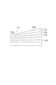
- FIG. 4 shows a graph showing strength characteristics when an oblique tensile force is applied to the unidirectional fiber-reinforced plastic member.
- This graph is shown in Taichi Fujii, Masaru Zako, “Destruction and Mechanics of Composite Materials”, Jikkyo Publishing Co., Ltd., 1989, page 89.
- the graph of the maximum work theory that matches well with the real value shows that the tensile strength is halved at an angle of 5 ° and about 70% at an angle of 5 ° compared to the tensile strength at an angle of 0 °. Become.
- the taper angle of the reverse taper shape of the end portion 100a of the first member 100 may be about 3 ° to 5 ° as described above, and the end portion 100a of the first member 100
- the inclination of the reinforcing fiber to be arranged from the axial direction may be 5 ° or less.
- the compression strength is halved at an angle of 5 °, and about 70% at 3 °.
- the first member 100 made of FRP only needs to have the end portion 100a in a reverse tapered shape. Therefore, it is not necessary to use a special shape that weakens the strength in order to join the first member 100 to the second member 200, and the joining structure 10 is configured while maintaining the strength of the first member 100 itself. be able to.
- the plurality of fibers included in the end portion 100a of the first member 100 are provided so that the angle with respect to the axial direction of the end portion 100a increases as the fiber is provided near the surface forming the reverse tapered shape. Therefore, the strength of the end portion 100a can be ensured. That is, according to the joining structure 10 according to the present embodiment, the joining structure 10 between the first member 100 made of FRP and the other member 200 can be easily and sufficiently, for example, capable of withstanding the compressive load from the joining portion 200a. High bonding strength can be achieved.
- the connecting portion 300b of the joining member 300 and the joining portion 200a of the second member 200 are fixed by screws, but the second portion is connected to the connecting portion 300b of the joining member 300 by other methods.
- the joint 200a of the member 200 may be pushed in and fixed.
- the second member 200 and the joining member 300 are made of metal, but may be made of other materials.
- first member 100 shown in FIG. 2 may be provided with a reinforcing member (stuffing) for supporting the inner peripheral surface in the cylindrical interior 100d of the end portion 100a.
- a reinforcing member for supporting the inner peripheral surface in the cylindrical interior 100d of the end portion 100a.
- the cylindrical end portion 100a may be prevented from being crushed inward in the circumferential direction.
- a hole communicating with the inside of the first member 100 may be provided in the end surface 200b in the second member 200.
- the second member 200 may be cylindrical (tubular), and fluid may flow inside the first member 100 and the second member 200.
- a sealing member such as an O-ring.
- the joining member 300 when the joining member 300 is composed of one member, an end portion on the side opposite to the end portion 100 a of the first member 100 (in the hole provided in the joining member 300 ( The joining member 300 needs to be connected to the end portion 100a of the first member 100 through the first member 100 from the left end portion (not shown in FIG. 2).
- the joining member 300 is cut into two, for example, in a cross section including the axis, and the member cut so as to cover the end portion 100a of the first member 100 in the contact portion 300a is bonded (for example, mechanically connected). Or bonding with an adhesive). This eliminates the need to pass the first member 100 through the hole provided in the joining member 300.
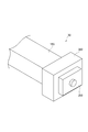
- the joining member 380 may be connected to the first member 180 from the end surface 180b on the side of the end portion 180a having the reverse tapered shape of the first member 180.
- FIG. 8 is a perspective view of the first member 180.
- FIG. 9A shows an end surface 180b on the end 180a side of the first member 180 having an inversely tapered shape
- FIG. 9B shows close contact with the first member 180 of the joining member 380.
- An end face 380c on the part 380a side is shown.
- the first member 180 is not reversely tapered over the entire outer circumferential surface of the end portion 180a, and only a part of the outer circumferential surface is reversed. Tapered shape. That is, the end portion 180a of the first member 180 has a portion 180d whose outer peripheral surface has a reverse taper shape and a portion 180e whose outer peripheral surface does not have a reverse taper shape in the circumferential direction. Yes.
- three portions 180d having a reverse taper shape are provided at equal intervals in the circumferential direction. Note that the number of the portions 180d provided is not necessarily three, and may be four, for example.
- the portion 180e whose outer peripheral surface is not reversely tapered is sandwiched between the portions 180d that are reversely tapered.
- the portion 180e has an outer diameter that is equal to or smaller than the outer diameter of the reverse tapered shape in the axial direction. More specifically, the outer diameter of the portion 180e is the portion where the reverse taper shape of the end portion 180a of the first member 180 is started (or the portion not having the reverse taper shape inside the end portion 180a). ) Is the same size as the outer diameter.
- the end surface 380c of the joining member 380 is provided with an opening 380f having the same shape as the end surface 100b of the first member 180.
- the end portion 180 a of the first member 180 is inserted into the opening 380 f of the joining member 380. Therefore, the opening 380f may be slightly larger than the shape of the end surface 180b of the first member 180 so that it can be easily inserted.
- the joining member 380 is provided with a groove having a shape of a portion 380d corresponding to the portion 180d of the opening 380f corresponding to the reverse tapered shape of the first member 180 in the axial direction.
- the axial length of the groove is the same as the axial length of the reverse taper shape.
- a portion 380e corresponding to the portion 180e that is not reversely tapered of the first member 180 has the same shape as the contact portion 300a of FIG. That is, the inner periphery of the portion 380e in the axial direction has a shape along the reverse tapered shape of the end portion 180a of the first member 180.
- the first member 180 and the joining member 380 have the above-described configuration, a structure (combined structure) that is fitted to each other can be taken. Specifically, the end 180a of the first member 180 is inserted into the joining member 380 from the opening 380f. After inserting the first member 180 into the joining member 380 by the axial length of the reverse tapered shape, the first member 180 is rotated in the circumferential direction with respect to the joining member 380. Accordingly, the reversely tapered portion 180d of the first member 180 is positioned at a portion 380e where the inner periphery of the bonding member 380 is shaped along the reverse tapered shape. That is, the portions 180d and 380e are in contact with each other as shown in FIG.
- the joining member 380 can be connected to the first member 180 from the end surface 180b on the end portion 180a side which is the inversely tapered shape of the first member 180.
- the first member 180 is a member that is very long in the axial direction, and when it is difficult to connect the joining member 380 from the side opposite to the end portion 180a of the first member 180, the joining member 380 and the first member 180 can be easily connected to each other.
- One member 180 can be connected.
- the first member 100 has the cylindrical shape of the end portion 100a, but it does not necessarily have to be cylindrical.
- the joining structure 20 may be configured by using a columnar member that is not provided with a hollow (hole) therein as the end 150 a of the first member 150.
- the second member 200 and the joining member 300 may be those shown in FIGS.
- the joining structure 30 may be configured using a first member 160, a second member 260, and a joining member 360 having a rectangular cross section. In that case, since the second member 260 and the joining member 360 cannot be connected by screwing, they are connected by any method other than screwing.
- the reverse tapered shape of the end portion 100a of the first member 100 is a shape in which the radial direction (outer diameter) of the outer peripheral surface increases as the end surface 100b of the first member 100 is approached.
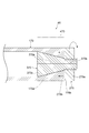
- the reverse taper shape may be a shape in which the size of the inner circumferential surface in the radial direction (inner diameter) becomes smaller as it approaches the end surface of the first member.
- FIG. 7 shows a cross section of the joining structure 40 in this case.
- the joining structure 40 includes a first member 170, a second member 270, and a joining member 370.
- the end 170a of the first member 170 has a cylindrical shape. Further, the end portion 170a of the first member 170 has a reverse taper shape in the axial direction inside the cylindrical shape. Specifically, the end 170a of the first member 170 has a shape in which the size of the inner circumferential surface in the radial direction (inner diameter) decreases as it approaches the end surface 170b of the first member 170. On the other hand, the radial direction (outer diameter) size of the outer peripheral surface of the end 170a of the first member 170 is constant. Also in the first member 170, the fibers can be oriented in the same manner as shown in FIG.
- the second member 270 to be joined to the first member 170 has a joint portion 270a that is a portion to be joined to the first member 170.
- the joint portion 270 a has a cylindrical shape whose outer diameter is approximately the same as the outer diameter of the end surface 170 b of the first member 170.
- the joint portion 270 a has one end surface 270 b that contacts the end surface 170 b of the first member 170.
- the axis of the end 170 a of the first member 170 and the axis of the joint 270 a of the second member 270 are located on the same straight line.
- the joining member 370 is a member that joins the first member 170 and the second member 270 together.
- the joining member 370 is provided in close contact with the reverse tapered shape of the inner peripheral surface of the end portion 170a of the first member 170 and is connected to the joining portion 270a of the second member 270.
- the joining member 370 is a cylindrical (partially conical) member.
- the diameter (outer diameter) of the outer peripheral surface of the joining member 300 varies depending on the position in the axial direction as described below.
- the joining member 370 is divided into an adhesion portion 370a that is in close contact with the end portion 170a of the first member 170 in the axial direction, and a connection portion 370b that is connected to the joining portion 270a of the second member 270.
- the length of the close contact portion 370a in the axial direction is the same as the length in the axial direction of the portion of the end portion 170a of the first member 170 that has an inversely tapered shape. Further, the inner periphery of the close contact portion 370 a has a shape along the reverse tapered shape of the end portion 170 a of the first member 170. That is, the outer diameter of the end portion of the contact portion 370 a on the connection portion 370 b side is the same as the inner diameter of the end surface 170 b of the first member 170.
- the outer diameter of the other end of the close contact portion 370a is a portion where the reverse taper shape of the end portion 170a of the first member 170 starts (or the reverse taper shape and It is the same size as the inner diameter of the part that is not.
- connection portion 370b of the joining member 370 and the outer peripheral surface of the joint portion 270a of the second member 270 are connected (fixed) by screwing.
- the connection portion 370 b of the bonding member 370 is squeezed and fixed to the inner peripheral surface (hole) of the bonding portion 270 a of the second member 270. Therefore, a thread groove is provided on the outer peripheral surface of the connecting portion 370b, and the diameter (outer diameter) of the outer peripheral surface is equal to the diameter (inner diameter) of the inner peripheral surface of the joint portion 270a of the second member 270. It depends on the size. Further, a screw groove is also provided on the inner peripheral surface of the joint portion 270a of the second member 270.
- the axial length of the connecting portion 370b is slightly longer than the axial length of the joint portion 270a.
- the joint structure 40 using an inversely tapered slope.
- the joint structure 40 using the first member 170 having an inner diameter of about 5 cm and a reverse taper angle of 3 ° can withstand a tensile load of about 10 t.
- size can be comprised.
- the end 170a of the first member 170 has a diameter from the contact portion 370a of the joining member 370. Forces outward in the direction. That is, a force is applied to increase the diameter of the end 170a. Therefore, in order to maintain the bonding strength, a reinforcing member 470 that is wound in the circumferential direction of the outer peripheral surface of the end portion 170a of the first member 170 is provided to prevent the diameter of the end portion 170a of the first member 170 from expanding. Also good.
- fiber reinforced plastic can be appropriately used as a member constituting a structure or the like.
- structures on land and at sea, in the sea, and under the sea (2) buildings, bridges, suspended structures, etc., (3) offshore structures such as floating bodies and platforms, (4) artificial Joints for space-related equipment such as satellite solar panel frames, (5)
- it can be used for medical purposes such as artificial legs.
Abstract
The present invention easily obtains sufficient joining strength in a joining structure between a fiber-reinforced plastic and another member. In a joining structure (10), a first member (100) made of a fiber-reinforced plastic and having a column-shaped end section (100a), and a second member (200) which is different from the first member (100) are joined. The end section (100a) has an inversely tapered shape in the axial direction, and a joining member (300) is provided along the inversely tapered shape of the end section (100a). The second member (200) is provided in contact with the end surface of the first member (100) and is connected to the joining member (300). A plurality of fibers (110a) extending in the axial direction of the end section (100a) are provided in the end section (100a) of the first member (100). The fibers (110a) are provided so that those nearer the surface constituting the inversely tapered shape, in the radial direction of the end section (100a), form a larger angle with the axial direction of the end section (100a).
Description
本発明は、繊維強化プラスチックからなる部材と別の部材との接合構造に関する。
The present invention relates to a joint structure between a member made of fiber reinforced plastic and another member.
従来から、構造物等を構成する部材としてFRP(Fiber Reinforced Plastics、繊維強化プラスチック)を用いるため、円筒状のFRPと金属とを接続させる接合構造が提案されている(例えば、特許文献1参照)。
Conventionally, since FRP (Fiber (Reinforced Plastics, fiber reinforced plastic) is used as a member constituting a structure or the like, a joining structure for connecting a cylindrical FRP and a metal has been proposed (for example, see Patent Document 1). .
しかし、特許文献1に記載されたようにボルトやリベットを用いて接合構造を構成した場合、FRPに穴をあける必要がある。FRPに穴があけられるとFRPに含まれる繊維が切られることとなりFRPの強度が低下する。また、締結の面積が小さいため、荷重が集中し、接合構造全体の強度が低くなってしまう。
However, when a joining structure is configured using bolts or rivets as described in Patent Document 1, it is necessary to make a hole in the FRP. When a hole is made in the FRP, fibers contained in the FRP are cut, and the strength of the FRP is lowered. In addition, since the fastening area is small, the load is concentrated and the strength of the entire joining structure is lowered.
また、FRPと金属との接合面に接着剤を塗布して貼付する等の接着による接合構造も考えられる。この構造では、接着面の汚れ、水分等が接合の強度に影響を及ぼす。また、接着剤の厚さが接合の強度に影響を及ぼす。また、温度等により接着剤の物性変化が起こりえる。上記のように接着による接合構造では、接合の強度に影響を及ぼす要素が多く、それらの管理が難しいという問題がある。
Also, a bonding structure by bonding such as applying an adhesive to the bonding surface between the FRP and the metal and sticking it can be considered. In this structure, dirt on the bonding surface, moisture, and the like affect the bonding strength. Also, the thickness of the adhesive affects the bonding strength. In addition, the physical properties of the adhesive may change due to temperature or the like. As described above, the bonding structure by bonding has a problem that there are many factors that affect the bonding strength, and it is difficult to manage them.
本発明は、上記の問題点に鑑みてなされたものであり、繊維強化プラスチックと別の部材との接合構造において容易に十分な接合強度を達成することができる接合構造を提供することを目的とする。
The present invention has been made in view of the above problems, and an object of the present invention is to provide a joint structure that can easily achieve sufficient joint strength in a joint structure between a fiber-reinforced plastic and another member. To do.
上記の目的を達成するために、本発明の一実施形態に係る接合構造は、繊維強化プラスチックからなる端部が柱状の第1の部材と第1の部材とは別の第2の部材との接合構造であって、第1の部材の端部は、軸方向において逆テーパ形状になっており、第1の部材の端部の逆テーパ形状に沿って設けられる接合用部材を備え、第2の部材は前記第1の部材の端面に接触して設けられると共に前記接合用部材に接続され、第1の部材の端部の内部には実質的に当該端部の軸方向に延びる複数の繊維が設けられており、複数の繊維は、前記第1の部材の端部の径方向において前記逆テーパ形状を構成する面の近くに設けられたもの程、当該端部の軸方向に対する角度が大きくなるように設けられる。
In order to achieve the above object, a joining structure according to an embodiment of the present invention includes a first member having a columnar end made of fiber-reinforced plastic and a second member different from the first member. In the joining structure, the end portion of the first member has an inversely tapered shape in the axial direction, and includes a joining member provided along the inversely tapered shape of the end portion of the first member. The member is provided in contact with the end surface of the first member and is connected to the joining member, and a plurality of fibers extending substantially in the axial direction of the end portion inside the end portion of the first member The plurality of fibers have a larger angle with respect to the axial direction of the end portion as the fiber is provided near the surface constituting the reverse tapered shape in the radial direction of the end portion of the first member. It is provided to become.
本発明の一実施形態に係る接合構造は、繊維強化プラスチックからなる第1の部材の端部の逆テーパ形状の傾斜を利用して第1の部材と第2の部材とが接合されたものであり、第1の部材と第2の部材とを引き離す力に耐えうる構造となっている。また、金属材料等で形成される第2の部材と接合させるために、繊維強化プラスチックからなる第1の部材は端部を逆テーパ形状にするだけでよく、第1の部材自体の強度を保ったまま接合構造を構成することができる。更に、第1の部材の端部に含まれる複数の繊維は、逆テーパ形状を構成する面の近くに設けられたもの程、当該端部の軸方向に対する角度が大きくなるように設けられているため、当該端部の強度を確保することができる。即ち、本発明の一実施形態に係る接合構造によれば、繊維強化プラスチックと別の部材との接合構造において容易に十分な接合強度を達成することができる。
The joining structure which concerns on one Embodiment of this invention is what joined the 1st member and the 2nd member using the reverse taper-shaped inclination of the edge part of the 1st member which consists of fiber reinforced plastics. There is a structure that can withstand the force of separating the first member and the second member. In addition, in order to join the second member formed of a metal material or the like, the first member made of fiber reinforced plastic only needs to have a reverse tapered shape at the end, and the strength of the first member itself is maintained. The junction structure can be configured as it is. Furthermore, the plurality of fibers included in the end portion of the first member are provided so that the angle with respect to the axial direction of the end portion increases as the fiber is provided near the surface forming the inversely tapered shape. Therefore, the strength of the end can be ensured. That is, according to the joint structure according to an embodiment of the present invention, sufficient joint strength can be easily achieved in the joint structure between the fiber reinforced plastic and another member.
前記逆テーパ形状は、前記第1の部材の端面に近づくにつれて外周面の径方向の大きさが大きくなる形状であることとしてもよい。この構成によれば、確実かつ容易に第1の部材を構成することができる。
The reverse tapered shape may be a shape in which the radial size of the outer peripheral surface increases as the end surface of the first member is approached. According to this configuration, the first member can be configured reliably and easily.
第1の部材の端部は、外周面における逆テーパ形状となっている部分の周方向の一部にその外径が当該逆テーパ形状の外径以下の大きさの部分を有しており、当該第1の部材と接合用部材とが嵌め合わされることとしてもよい。この構成によれば、接合用部材を第1の部材の逆テーパ形状となっている端部側の端面から第1の部材に接続させることができる。
The end of the first member has a portion whose outer diameter is equal to or smaller than the outer diameter of the reverse tapered shape in a part of the circumferential direction of the portion that is the reverse tapered shape on the outer peripheral surface, The first member and the joining member may be fitted together. According to this configuration, the joining member can be connected to the first member from the end surface on the end side that is the inversely tapered shape of the first member.
また、この場合、前記第1の部材の端部は、筒状であり、筒状の前記第1の部材の端部の内部に内周面を支持する補強部材が設けられる、こととしてもよい。この構成によれば、筒状の第1の部材の端部が内側につぶれることを防止することができる。
In this case, the end portion of the first member may be cylindrical, and a reinforcing member that supports the inner peripheral surface may be provided inside the end portion of the cylindrical first member. . According to this structure, it can prevent that the edge part of a cylindrical 1st member is crushed inside.
前記第1の部材の端部は、筒状であり、前記逆テーパ形状は、前記第1の部材の端面に近づくにつれて内周面の径方向の大きさが小さくなる形状であり、前記接合用部材は、筒状の前記第1の部材の端部の内部に設けられる、こととしてもよい。この構成によれば、第1の部材の端部の外径を一定の大きさとする接合構造を構成することができる。
The end portion of the first member is cylindrical, and the reverse tapered shape is a shape in which the radial size of the inner peripheral surface decreases as the end surface of the first member is approached. The member may be provided inside the end portion of the cylindrical first member. According to this structure, the joining structure which makes the outer diameter of the edge part of a 1st member a fixed magnitude | size can be comprised.
また、この場合、筒状の前記第1の部材の端部の外周面の周方向に巻き付けられる補強部材が設けられることとしてもよい。この構成によれば、接合強度を更に大きくすることができる。
In this case, a reinforcing member wound around the outer peripheral surface of the end portion of the cylindrical first member may be provided. According to this configuration, the bonding strength can be further increased.
前記逆テーパ形状の前記第1の部材の端部の軸方向に対する角度は、3°~5°の何れかであることとしてもよい。この構成によれば、第1の部材の逆テーパ形状の端部を、第1の部材と第2の部材との接合強度をより大きいものとすることができる。
The angle with respect to the axial direction of the end portion of the first member having the inversely tapered shape may be any of 3 ° to 5 °. According to this configuration, it is possible to increase the bonding strength between the first member and the second member at the end portion of the inversely tapered shape of the first member.
前記第1の部材が、炭素繊維強化プラスチックからなることとしてもよい。前記別の第2の部材が、金属からなることとしてもよい。
The first member may be made of carbon fiber reinforced plastic. The other second member may be made of metal.
本発明の一実施形態によれば、繊維強化プラスチックと別の部材との接合構造において容易に十分な接合強度を達成することができる。
According to an embodiment of the present invention, sufficient joint strength can be easily achieved in a joint structure between a fiber reinforced plastic and another member.
以下、図面と共に本発明に係る接合構造の実施形態について詳細に説明する。なお、図面の説明においては同一要素には同一符号を付し、重複する説明を省略する。また、図面の寸法比率は、説明のものと必ずしも一致していない。
Hereinafter, embodiments of the joint structure according to the present invention will be described in detail with reference to the drawings. In the description of the drawings, the same elements are denoted by the same reference numerals, and redundant description is omitted. Further, the dimensional ratios in the drawings do not necessarily match those described.
図1に本実施形態に係る接合構造10の斜視図を示す。接合構造10は、端部が柱状の第1の部材100と、第1の部材とは別体として構成される第2の部材200とを接合させる構造である。なお、本実施形態において柱状とは、外周面を有し側面において柱状と同様となる筒状等の形状を含む。接合構造10は、第1の部材100と第2の部材200とを接合させる接合用部材300を含んで構成されている。第1の部材100は、FRPからなる部材である。本実施形態に係る接合構造10は、例えば、FRPからなる第1の部材100を、構造物を構成する部材として用いるために他の部材と接合させるためのものである。
FIG. 1 shows a perspective view of a joining structure 10 according to the present embodiment. The joining structure 10 is a structure that joins a first member 100 having a columnar end and a second member 200 configured as a separate body from the first member. In the present embodiment, the columnar shape includes a cylindrical shape having an outer peripheral surface and similar to the columnar shape on the side surface. The joining structure 10 includes a joining member 300 that joins the first member 100 and the second member 200 together. The first member 100 is a member made of FRP. The joint structure 10 according to the present embodiment is for joining the first member 100 made of, for example, FRP with another member in order to use it as a member constituting the structure.
第1の部材100を構成するFRPとしては、例えば、CRFP(Carbon Fiber Reinforced Plastics、炭素繊維強化プラスチック)が用いられる。あるいは、それ以外にも、例えば、GRFP(Glass Fiber Reinforced Plastics、ガラス繊維強化プラスチック)やAFRP(Aramid Fiber Reinforced Plastics、アラミド繊維強化プラスチック)等が用いられてもよい。また、第1の部材100の端部100aには、その軸方向及び周方向の2方向に繊維を配向することができる。これにより、第1の部材100及び接合構造10の強度を高めることができる。
As the FRP configuring the first member 100, for example, CRFP (Carbon Fiber Reinforced Plastics, carbon fiber reinforced plastic) is used. Alternatively, for example, GRFP (Glass FiberforceReinforced Plastics, glass fiber reinforced plastic) or AFRP (Aramid Fiber Reinforced Plastics, aramid fiber reinforced plastic) may be used. In addition, fibers can be oriented in the two directions of the axial direction and the circumferential direction at the end portion 100a of the first member 100. Thereby, the intensity | strength of the 1st member 100 and the joining structure 10 can be raised.
図1及び図2に示すように、第1の部材100の端部100aは、円筒状の形状(FRPパイプ)をしている。また、第1の部材100の端部100aは、軸方向において逆テーパ形状になっている。具体的には、第1の部材100の端部100aは、軸方向において第1の部材100の端面100bに近づくにつれて外周面の径方向(外径)の大きさが大きくなる形状である。この逆テーパ形状は、後述するように第1の部材100の端部100aに第2の部材を固定するためのものである。逆テーパ形状になっている第1の部材100の端部100aは、軸方向で端面100bから一定の長さの部分である。端部100aの逆テーパ形状のテーパ角(端部100aの軸方向に対する角度)θは、第1の部材100と接合用部材300との固定の強度を考慮して、3°~5°の何れかであることとしてもよく、例えば、3°とすることができる。但し、使用目的等に応じた強度が確保できれば、必ずしも上記の角度とする必要はない。一方で、第1の部材100の端部100aの内周面の径方向(内径)の大きさは一定である。
As shown in FIGS. 1 and 2, the end portion 100a of the first member 100 has a cylindrical shape (FRP pipe). Moreover, the edge part 100a of the 1st member 100 is reverse taper shape in the axial direction. Specifically, the end portion 100a of the first member 100 has a shape in which the radial direction (outer diameter) of the outer peripheral surface increases as it approaches the end surface 100b of the first member 100 in the axial direction. The reverse taper shape is for fixing the second member to the end portion 100a of the first member 100 as will be described later. The end portion 100a of the first member 100 having a reverse taper shape is a portion having a certain length from the end surface 100b in the axial direction. The taper angle (angle with respect to the axial direction of the end portion 100a) θ of the end portion 100a is 3 ° to 5 ° in consideration of the fixing strength between the first member 100 and the joining member 300. For example, the angle may be 3 °. However, if the strength according to the purpose of use and the like can be ensured, the above-described angle is not necessarily required. On the other hand, the size in the radial direction (inner diameter) of the inner peripheral surface of the end portion 100a of the first member 100 is constant.
図3に第1の部材100の端部100aにおける、第1の部材100の軸方向に延びる繊維の配置を示す。第1の部材100の端部100aにおける繊維の配置は、例えば、図3に示す配置に示す配置とすることができる。
FIG. 3 shows the arrangement of fibers extending in the axial direction of the first member 100 at the end 100a of the first member 100. FIG. The arrangement of the fibers at the end 100a of the first member 100 can be, for example, the arrangement shown in the arrangement shown in FIG.
この繊維の配置では、実質的に第1の部材100の軸方向に延びる複数の繊維110aは、第1の部材100の端部100aにおいて径方向の外側に設けられたもの程、当該第1の部材100の軸方向に対する角度が大きくなるように設けられる。即ち、複数の繊維110aは、第1の部材100の端部100aの径方向において逆テーパ形状を構成する面の近くに設けられたもの程、当該端部100aの軸方向に対する角度が大きくなるように設けられる。軸方向に設けられた繊維110aは、軸方向における逆テーパ形状となっている部分との境目100cで、逆テーパ形状と同様の方向に折れ曲がっている。また、各繊維110aは径方向の外側に設けられたもの程、端部100aのテーパ角に近づくように角度が大きくなっている。このように繊維110aを配置することで、接合構造10を構成する上で十分な第1の部材100の強度を確保することができる。これは、径方向の内側に設けられた物程、折れ曲がりの角度が小さく、強度が高く保てることによる。詳細については、後述する。
In the arrangement of the fibers, the plurality of fibers 110a extending substantially in the axial direction of the first member 100 are arranged on the outer side in the radial direction at the end portion 100a of the first member 100. The member 100 is provided so that the angle with respect to the axial direction becomes large. That is, as the plurality of fibers 110a are provided closer to the surface forming the reverse tapered shape in the radial direction of the end portion 100a of the first member 100, the angle of the end portion 100a with respect to the axial direction is increased. Provided. The fiber 110a provided in the axial direction is bent in the same direction as the reverse tapered shape at the boundary 100c with the portion having the reverse tapered shape in the axial direction. Each fiber 110a has a larger angle so as to be closer to the taper angle of the end portion 100a as it is provided on the outer side in the radial direction. By arranging the fibers 110a in this way, the strength of the first member 100 sufficient for configuring the joint structure 10 can be ensured. This is due to the fact that the angle provided at the inner side in the radial direction is smaller and the strength is kept high. Details will be described later.
第1の部材100との接合対象となる第2の部材200は、第1の部材100と接合される部分である接合部200aを有している。接合部200aは、その外径が第1の部材100の端面100bの外径と同程度の大きさの円柱状の形状である。接合部200aは、第1の部材100の端面100bに接触する一方の端面200bを有している。第2の部材200は、接合部200aのもう一方の端面側において接合部200aと一体に形成された第2の部材本体200cを有している。第2の部材本体200cは、例えば、その外径が接合部200aよりも小さい円柱状の形状である。接合部200aの軸線と第2の部材本体200cの軸線とは同一直線上に位置している。なお、第2の部材本体200cは、接合構造10とは直接関係するものではないので、任意の形状をとることができる。
The second member 200 to be joined to the first member 100 has a joint portion 200a that is a portion to be joined to the first member 100. The joint portion 200 a has a columnar shape whose outer diameter is approximately the same as the outer diameter of the end surface 100 b of the first member 100. The joint portion 200 a has one end surface 200 b that contacts the end surface 100 b of the first member 100. The second member 200 has a second member main body 200c formed integrally with the joint portion 200a on the other end face side of the joint portion 200a. The second member main body 200c has, for example, a cylindrical shape whose outer diameter is smaller than that of the joint portion 200a. The axis of the joint part 200a and the axis of the second member main body 200c are located on the same straight line. Note that the second member main body 200c is not directly related to the bonding structure 10, and can take any shape.
また、接合構造10において、第1の部材100の端部100aの軸線と、第2の部材200の接合部200aの軸線とは同一直線上に位置している。また、第2の部材200側(例えば、第2の部材本体200c部分)に従来から用いられている締結構造を別途設けて更に別の部材との接合を可能とすることとしてもよい。
Also, in the joint structure 10, the axis of the end 100a of the first member 100 and the axis of the joint 200a of the second member 200 are located on the same straight line. Moreover, it is good also as providing the fastening structure conventionally used in the 2nd member 200 side (for example, 2nd member main body 200c part) separately, and enabling joining with another member.
接合用部材300は、第1の部材100と第2の部材200とを接合させる部材である。接合用部材300は、円筒状の部材である。接合用部材300は、第1の部材100の端部100aの外周面の逆テーパ形状に沿うように密着させて設けられると共に第2の部材200の接合部200aと接続される。接合用部材300の外周面の径(外径)は、第1の部材100の端部100a及び第2の部材200の接合部200aの外径よりも大きく、軸方向に渡って同じ大きさである。接合用部材300の内周面の径(内径)は、以下に説明するように軸方向に位置によって異なる。接合用部材300は、軸方向において第1の部材100の端部100aと密着する密着部300aと、第2の部材200の接合部200aと接続される接続部300bとに分けられる。
The joining member 300 is a member that joins the first member 100 and the second member 200 together. The joining member 300 is a cylindrical member. The joining member 300 is provided in close contact with the reverse tapered shape of the outer peripheral surface of the end portion 100 a of the first member 100 and is connected to the joining portion 200 a of the second member 200. The diameter (outer diameter) of the outer peripheral surface of the joining member 300 is larger than the outer diameter of the end portion 100a of the first member 100 and the joining portion 200a of the second member 200, and has the same size in the axial direction. is there. The diameter (inner diameter) of the inner peripheral surface of the joining member 300 varies depending on the position in the axial direction as described below. The joining member 300 is divided into an adhesion portion 300a that is in close contact with the end portion 100a of the first member 100 in the axial direction, and a connection portion 300b that is connected to the joining portion 200a of the second member 200.
密着部300aの軸方向の長さは、第1の部材100の端部100aの逆テーパ形状となっている部分の軸方向の長さと同じ長さである。また、密着部300aの内周は、第1の部材100の端部100aの逆テーパ形状に沿った形状となっている。即ち、密着部300aの接続部300b側端部の内径は、第1の部材100の端面100bの外径と同じ大きさである。また、密着部300aの開口部側端部(密着部300aの端面300c側)の内径は、第1の部材100の端部100aの逆テーパ形状が開始される部分(あるいは、逆テーパ形状となっていない部分)の外径と同じ大きさである。
The length in the axial direction of the contact portion 300a is the same as the length in the axial direction of the portion of the end portion 100a of the first member 100 that has an inversely tapered shape. Further, the inner periphery of the close contact portion 300 a has a shape along the reverse tapered shape of the end portion 100 a of the first member 100. That is, the inner diameter of the end portion of the contact portion 300 a on the connection portion 300 b side is the same as the outer diameter of the end surface 100 b of the first member 100. Further, the inner diameter of the end portion on the opening side of the close contact portion 300a (the end surface 300c side of the close contact portion 300a) is the portion where the reverse taper shape of the end portion 100a of the first member 100 starts (or the reverse taper shape). It is the same size as the outer diameter.
接合用部材300の接続部300bの内周面と、第2の部材200の接合部200aの外周面とは、ネジ止めによって接続(固定)される。即ち、第2の部材200の接合部200aが、接合用部材300の接続部300bの内周面(穴)に絞め込まれて固定される。そのため、接続部300bの内周面にはネジ溝が設けられており、当該内周面の径(内径)の大きさは第2の部材200の接合部200aの外周面の径(外径)の大きさに応じたものとなっている。また、第2の部材200の接合部200aの外周面にもネジ溝が設けられている。また、接続部300bの軸方向の長さは、接合部200aの軸方向の長さよりもわずかに短い程度とする。
The inner peripheral surface of the connection part 300b of the joining member 300 and the outer peripheral surface of the joint part 200a of the second member 200 are connected (fixed) by screwing. That is, the joint portion 200a of the second member 200 is squeezed and fixed to the inner peripheral surface (hole) of the connection portion 300b of the joint member 300. Therefore, a thread groove is provided on the inner peripheral surface of the connection portion 300b, and the diameter (inner diameter) of the inner peripheral surface is the diameter (outer diameter) of the outer peripheral surface of the joint portion 200a of the second member 200. According to the size of the. Further, a thread groove is also provided on the outer peripheral surface of the joint portion 200 a of the second member 200. The axial length of the connecting portion 300b is slightly shorter than the axial length of the joint portion 200a.
図1及び図2に示すように接続部300bと接合部200aとがネジ止めされて接合部200aの端面200bが第1の部材100の端面100bに突き当たったときに、接合部200aがわずかに接続部300bから出ている。なお、接合構造10において、ネジ止めされる部分及び密着されて固定される部分については、接着剤等でより接続強度が強くなるように接着されていてもよい。第2の部材200及び接合用部材300は、例えば、金属材料で(金具として)形成されている。例えば、機械構造用鋼材、アルミニウム等によって形成される。
As shown in FIGS. 1 and 2, when the connecting portion 300 b and the joint portion 200 a are screwed and the end surface 200 b of the joint portion 200 a hits the end surface 100 b of the first member 100, the joint portion 200 a is slightly connected. It comes out from the part 300b. In addition, in the joining structure 10, about the part screwed and the part closely_contact | adhered and fixed, you may adhere | attach so that connection strength may become stronger with an adhesive agent. The second member 200 and the joining member 300 are made of, for example, a metal material (as a metal fitting). For example, it is formed of steel for machine structure, aluminum or the like.
このように、接合用部材300の密着部300aと第1の部材100の端部100aとが密着し、また、接合部200aの端面200bが第1の部材100の端面100bに突き当たるように接合用部材300の接続部300bと第2の部材200の接合部200aとが接続されることで、第1の部材100の端部100aと第2の部材200の接合部200aとが接合される。即ち、本実施形態に係る接合構造10は、第1の部材100の端部100aの逆テーパ形状の傾斜を利用して第1の部材100と第2の部材200とが接合されている。
Thus, the contact portion 300a of the joining member 300 and the end portion 100a of the first member 100 are in close contact, and the end surface 200b of the joint portion 200a is in contact with the end surface 100b of the first member 100. By connecting the connection part 300b of the member 300 and the joint part 200a of the second member 200, the end part 100a of the first member 100 and the joint part 200a of the second member 200 are joined. That is, in the joining structure 10 according to the present embodiment, the first member 100 and the second member 200 are joined by using the reverse tapered inclination of the end portion 100a of the first member 100.
第1の部材100と第2の部材200との間にそれらを引き離す力(図2の紙面において左右に引っ張る力)が加わると、接合用部材300の密着部300aには第1の部材100の端部100aの外周面からの力F1が加わる。第1の部材100の端部100aと接合用部材300の密着部300aとは、逆テーパの面で密着されているので一箇所に力が集中することなく、引き離す力(引張荷重)に耐えうる構造となっている。
When a force for pulling them apart between the first member 100 and the second member 200 (a force pulling left and right in the drawing of FIG. 2) is applied, the close contact portion 300a of the joining member 300 has the first member 100 A force F1 from the outer peripheral surface of the end portion 100a is applied. Since the end portion 100a of the first member 100 and the contact portion 300a of the joining member 300 are in close contact with each other with a reverse taper surface, they can withstand a pulling force (tensile load) without concentrating the force in one place. It has a structure.
また、第1の部材100と第2の部材200との間に圧縮する力(図2の紙面において、左右の端から中央に加わる力)が加わると、第1の部材100の端面100bには、第2の部材200の接合部200aからの力F2が加わる。しかし、第1の部材100の端面100bと第2の部材200の接合部200a側の端面200bとは、突き当たっているので圧縮荷重にも耐えることができる。
Further, when a compressing force is applied between the first member 100 and the second member 200 (a force applied from the left and right ends to the center in the drawing of FIG. 2), the end surface 100b of the first member 100 is applied to the end surface 100b. A force F2 from the joint portion 200a of the second member 200 is applied. However, since the end surface 100b of the first member 100 and the end surface 200b of the second member 200 on the side of the joint portion 200a are in contact with each other, they can withstand a compressive load.
ここで、図4に一方向繊維強化プラスチック部材に斜め方向の引張りの力が加えられた場合の強度特性を示すグラフを示す。このグラフは、藤井太一,座古勝,「複合材料の破壊と力学」,実教出版株式会社,1978年の第89頁に示されているグラフである。この中で、実数値と良く整合する最大仕事説のグラフを見ると、角度0°のときの引張り強度に対して、角度5°で引張り強度は半分になり、3°だと70%程度となる。それを考慮して、第1の部材100の端部100aの逆テーパ形状のテーパ角は、上述したように3°~5°程度としてもよく、また、第1の部材100の端部100aに配置される強化繊維の、軸方向からの傾きも5°以下であることとしてもよい。圧縮も同様に、角度5°で圧縮強度は半分になり、3°だと70%程度となる。
Here, FIG. 4 shows a graph showing strength characteristics when an oblique tensile force is applied to the unidirectional fiber-reinforced plastic member. This graph is shown in Taichi Fujii, Masaru Zako, “Destruction and Mechanics of Composite Materials”, Jikkyo Publishing Co., Ltd., 1989, page 89. Of these, the graph of the maximum work theory that matches well with the real value shows that the tensile strength is halved at an angle of 5 ° and about 70% at an angle of 5 ° compared to the tensile strength at an angle of 0 °. Become. In consideration thereof, the taper angle of the reverse taper shape of the end portion 100a of the first member 100 may be about 3 ° to 5 ° as described above, and the end portion 100a of the first member 100 The inclination of the reinforcing fiber to be arranged from the axial direction may be 5 ° or less. Similarly, the compression strength is halved at an angle of 5 °, and about 70% at 3 °.
また、接合構造10を構成するために、FRPからなる第1の部材100は端部100aを逆テーパ形状にするだけでよい。従って、第1の部材100を第2の部材200と接合させるために強度を弱めるような特別な形状にする必要がなく、第1の部材100自体の強度を保ったまま接合構造10を構成することができる。
Further, in order to configure the joint structure 10, the first member 100 made of FRP only needs to have the end portion 100a in a reverse tapered shape. Therefore, it is not necessary to use a special shape that weakens the strength in order to join the first member 100 to the second member 200, and the joining structure 10 is configured while maintaining the strength of the first member 100 itself. be able to.
更に、第1の部材100の端部100aに含まれる複数の繊維は、逆テーパ形状を構成する面の近くに設けられたもの程、当該端部100aの軸方向に対する角度が大きくなるように設けられているため、当該端部100aの強度を確保することができる。即ち、本実施形態に係る接合構造10によれば、前述した接合部200aからの圧縮荷重に耐えられる等、FRPからなる第1の部材100と別の部材200との接合構造10において容易に十分な接合強度を達成することができる。
Further, the plurality of fibers included in the end portion 100a of the first member 100 are provided so that the angle with respect to the axial direction of the end portion 100a increases as the fiber is provided near the surface forming the reverse tapered shape. Therefore, the strength of the end portion 100a can be ensured. That is, according to the joining structure 10 according to the present embodiment, the joining structure 10 between the first member 100 made of FRP and the other member 200 can be easily and sufficiently, for example, capable of withstanding the compressive load from the joining portion 200a. High bonding strength can be achieved.
上記の例では、接合用部材300の接続部300bと第2の部材200の接合部200aとはネジ止めによって固定されているが、それ以外の方法で接合用部材300の接続部300bに第2の部材200の接合部200aを押し込んで固定してもよい。また、第2の部材200及び接合用部材300は、金属で構成されることとしたがそれ以外の材質で構成されていてもよい。
In the above example, the connecting portion 300b of the joining member 300 and the joining portion 200a of the second member 200 are fixed by screws, but the second portion is connected to the connecting portion 300b of the joining member 300 by other methods. The joint 200a of the member 200 may be pushed in and fixed. Further, the second member 200 and the joining member 300 are made of metal, but may be made of other materials.
また、図2に示す第1の部材100は端部100aの筒状の内部100dに内周面を支持する補強部材(詰め物)を設けることとしてもよい。この構成によれば、筒状の端部100aが周方向の内側につぶれることを防いでもよい。
Further, the first member 100 shown in FIG. 2 may be provided with a reinforcing member (stuffing) for supporting the inner peripheral surface in the cylindrical interior 100d of the end portion 100a. According to this configuration, the cylindrical end portion 100a may be prevented from being crushed inward in the circumferential direction.
また、例えば、第2の部材200の内部に端面200bにおいて第1の部材100の内側と連通する孔が設けられていてもよい。即ち、第2の部材200が筒状(管状)となっていて、第1の部材100と第2の部材200との内部で流体が流れるようになっていてもよい。その場合、流体が第1の部材100及び第2の部材200の外部に漏れないように第1の部材100と接合用部材300との間、第2の部材200と接合用部材300との間をOリング等のシール部材によりシールすることとしてもよい。
Further, for example, a hole communicating with the inside of the first member 100 may be provided in the end surface 200b in the second member 200. In other words, the second member 200 may be cylindrical (tubular), and fluid may flow inside the first member 100 and the second member 200. In that case, between the first member 100 and the joining member 300 and between the second member 200 and the joining member 300 so that the fluid does not leak outside the first member 100 and the second member 200. May be sealed with a sealing member such as an O-ring.
また、上述した構成では、接合用部材300が1つの部材から構成されている場合には、接合用部材300に設けられる孔に第1の部材100の端部100aとは逆側の端部(図2では図示しない左側の端部)から第1の部材100を通して第1の部材100の端部100aに接合用部材300を接続させる必要がある。しかし、接合用部材300を、例えば、軸線を含む断面で2つに切断し、密着部300aにおいて第1の部材100の端部100aを覆うように切断した部材を接着(例えば、機械的な接続や接着剤による接着)させることとしてもよい。これにより、接合用部材300に設けられる孔に第1の部材100を通す必要がなくなる。
Further, in the above-described configuration, when the joining member 300 is composed of one member, an end portion on the side opposite to the end portion 100 a of the first member 100 (in the hole provided in the joining member 300 ( The joining member 300 needs to be connected to the end portion 100a of the first member 100 through the first member 100 from the left end portion (not shown in FIG. 2). However, the joining member 300 is cut into two, for example, in a cross section including the axis, and the member cut so as to cover the end portion 100a of the first member 100 in the contact portion 300a is bonded (for example, mechanically connected). Or bonding with an adhesive). This eliminates the need to pass the first member 100 through the hole provided in the joining member 300.
また、図8及び図9に示すように接合用部材380を、第1の部材180の逆テーパ形状となった端部180a側の端面180bから第1の部材180と接続できる構成としてもよい。図8は、第1の部材180の斜視図である。図9(a)は、第1の部材180の逆テーパ形状となった端部180a側の端面180bを示し、図9(b)は、接合用部材380の第1の部材180に密着する密着部380a側の端面380cを示している。
8 and 9, the joining member 380 may be connected to the first member 180 from the end surface 180b on the side of the end portion 180a having the reverse tapered shape of the first member 180. FIG. 8 is a perspective view of the first member 180. FIG. 9A shows an end surface 180b on the end 180a side of the first member 180 having an inversely tapered shape, and FIG. 9B shows close contact with the first member 180 of the joining member 380. An end face 380c on the part 380a side is shown.
図8及び図9(a)に示すように、第1の部材180は、端部180aの外周面の周方向全般に渡って逆テーパ形状となっておらず、外周面の一部のみが逆テーパ形状となっている。即ち、第1の部材180の端部180aは、周方向に、その外周面が逆テーパ形状となっている部分180dと、その外周面が逆テーパ形状となっていない部分180eとを有している。逆テーパ形状となっている部分180dは、例えば、周方向に等間隔で3か所設けられている。なお、当該部分180dが設けられる数は必ずしも3つでなくてもよく、例えば4つでもよい。その外周面が逆テーパ形状となっていない部分180eは、逆テーパ形状となっている部分180dに挟まれている。当該部分180eは、軸方向に渡ってその外径が当該逆テーパ形状の外径以下の大きさとなっている。より具体的には、当該部分180eの外径は、第1の部材180の端部180aの逆テーパ形状が開始される部分(あるいは、端部180aよりも内側の逆テーパ形状となっていない部分)の外径と同じ大きさである。
As shown in FIGS. 8 and 9A, the first member 180 is not reversely tapered over the entire outer circumferential surface of the end portion 180a, and only a part of the outer circumferential surface is reversed. Tapered shape. That is, the end portion 180a of the first member 180 has a portion 180d whose outer peripheral surface has a reverse taper shape and a portion 180e whose outer peripheral surface does not have a reverse taper shape in the circumferential direction. Yes. For example, three portions 180d having a reverse taper shape are provided at equal intervals in the circumferential direction. Note that the number of the portions 180d provided is not necessarily three, and may be four, for example. The portion 180e whose outer peripheral surface is not reversely tapered is sandwiched between the portions 180d that are reversely tapered. The portion 180e has an outer diameter that is equal to or smaller than the outer diameter of the reverse tapered shape in the axial direction. More specifically, the outer diameter of the portion 180e is the portion where the reverse taper shape of the end portion 180a of the first member 180 is started (or the portion not having the reverse taper shape inside the end portion 180a). ) Is the same size as the outer diameter.
図9(b)に示すように、接合用部材380の端面380cには、第1の部材180の端面100bと同一の形状の開口380fが設けられている。接合用部材380の開口380fには、第1の部材180の端部180aが挿入される。従って、挿入しやすいように開口380fは第1の部材180の端面180bの形状よりもわずかに大きくしてもよい。接合用部材380には、当該開口380fにおける、第1の部材180の逆テーパ形状となっている部分180dに対応する部分380dの形状の溝が軸方向に向かって設けられている。この溝の軸方向の長さは、逆テーパ形状の軸方向の長さと同じである。また、接合用部材380において、第1の部材180の逆テーパ形状となっていない部分180eに対応する部分380eは、上述した図2の密着部300aと同様の形状となっている。即ち、当該部分380eの軸方向に向かう内周は、第1の部材180の端部180aの逆テーパ形状に沿った形状となっている。
As shown in FIG. 9B, the end surface 380c of the joining member 380 is provided with an opening 380f having the same shape as the end surface 100b of the first member 180. The end portion 180 a of the first member 180 is inserted into the opening 380 f of the joining member 380. Therefore, the opening 380f may be slightly larger than the shape of the end surface 180b of the first member 180 so that it can be easily inserted. The joining member 380 is provided with a groove having a shape of a portion 380d corresponding to the portion 180d of the opening 380f corresponding to the reverse tapered shape of the first member 180 in the axial direction. The axial length of the groove is the same as the axial length of the reverse taper shape. Further, in the joining member 380, a portion 380e corresponding to the portion 180e that is not reversely tapered of the first member 180 has the same shape as the contact portion 300a of FIG. That is, the inner periphery of the portion 380e in the axial direction has a shape along the reverse tapered shape of the end portion 180a of the first member 180.
第1の部材180と接合用部材380とは上記の構成となっているため、互いに嵌め合わされる構造(篏合構造)をとることができる。具体的には、第1の部材180の端部180aを、開口380fから接合用部材380に挿入する。逆テーパ形状の軸方向の長さ分、第1の部材180を接合用部材380に挿入した後、第1の部材180を接合用部材380に対して周方向に回転させる。これにより、第1の部材180の逆テーパの部分180dが、接合用部材380の内周が逆テーパ形状に沿った形状となっている部分380eの部分に位置する。即ち、それらの部分180d,380eが図2に示したものと同様に接触する。
Since the first member 180 and the joining member 380 have the above-described configuration, a structure (combined structure) that is fitted to each other can be taken. Specifically, the end 180a of the first member 180 is inserted into the joining member 380 from the opening 380f. After inserting the first member 180 into the joining member 380 by the axial length of the reverse tapered shape, the first member 180 is rotated in the circumferential direction with respect to the joining member 380. Accordingly, the reversely tapered portion 180d of the first member 180 is positioned at a portion 380e where the inner periphery of the bonding member 380 is shaped along the reverse tapered shape. That is, the portions 180d and 380e are in contact with each other as shown in FIG.
上記の構成によれば、接合用部材380を第1の部材180の逆テーパ形状となっている端部180a側の端面180bから第1の部材180に接続させることができる。特に第1の部材180が軸方向に非常に長い部材の場合等、接合用部材380を第1の部材180の端部180aとは逆側から接続しづらい場合、容易に接合用部材380と第1の部材180とを接続することができる。
According to the above configuration, the joining member 380 can be connected to the first member 180 from the end surface 180b on the end portion 180a side which is the inversely tapered shape of the first member 180. In particular, when the first member 180 is a member that is very long in the axial direction, and when it is difficult to connect the joining member 380 from the side opposite to the end portion 180a of the first member 180, the joining member 380 and the first member 180 can be easily connected to each other. One member 180 can be connected.
上述した接合構造10では、第1の部材100は端部100aの筒状の形状としていたが必ずしも筒状である必要はない。例えば、図5の断面図に示すように、内部に中空(穴)が設けられていない円柱状の部材を第1の部材150の端部150aとして用いて接合構造20を構成することとしてもよい。なお、この場合も第2の部材200及び接合用部材300は、図1及び図2に示したものを用いることができる。
In the joint structure 10 described above, the first member 100 has the cylindrical shape of the end portion 100a, but it does not necessarily have to be cylindrical. For example, as shown in the cross-sectional view of FIG. 5, the joining structure 20 may be configured by using a columnar member that is not provided with a hollow (hole) therein as the end 150 a of the first member 150. . Also in this case, the second member 200 and the joining member 300 may be those shown in FIGS.
上述した接合構造10,20では、断面が円形状の部材を用いたが必ずしも円形状の部材を用いなくてもよい。例えば、図6の斜視図に示すように、断面が矩形となるような第1の部材160、第2の部材260及び接合用部材360を用いて接合構造30を構成することとしてもよい。その場合、第2の部材260と接合用部材360とはネジ止めによる接続ができないため、ネジ止め以外の任意の方法で接続させる。
In the joint structures 10 and 20 described above, a member having a circular cross section is used, but a circular member is not necessarily used. For example, as shown in the perspective view of FIG. 6, the joining structure 30 may be configured using a first member 160, a second member 260, and a joining member 360 having a rectangular cross section. In that case, since the second member 260 and the joining member 360 cannot be connected by screwing, they are connected by any method other than screwing.
上述した接合構造10では、第1の部材100の端部100aの逆テーパ形状は、第1の部材100の端面100bに近づくにつれて外周面の径方向(外径)の大きさが大きくなる形状であった。しかし、逆テーパ形状は、第1の部材の端面に近づくにつれて内周面の径方向(内径)の大きさが小さくなる形状とすることとしてもよい。この場合の接合構造40の断面を図7に示す。接合構造40は、第1の部材170と、第2の部材270と、接合用部材370とを備えて構成されている。
In the joining structure 10 described above, the reverse tapered shape of the end portion 100a of the first member 100 is a shape in which the radial direction (outer diameter) of the outer peripheral surface increases as the end surface 100b of the first member 100 is approached. there were. However, the reverse taper shape may be a shape in which the size of the inner circumferential surface in the radial direction (inner diameter) becomes smaller as it approaches the end surface of the first member. FIG. 7 shows a cross section of the joining structure 40 in this case. The joining structure 40 includes a first member 170, a second member 270, and a joining member 370.
図7に示すように、第1の部材170の端部170aは、円筒状の形状をしている。また、第1の部材170の端部170aは、筒状の内側で軸方向において逆テーパ形状になっている。具体的には、第1の部材170の端部170aは、第1の部材170の端面170bに近づくにつれて内周面の径方向(内径)の大きさが小さくなる形状である。一方で、第1の部材170の端部170aの外周面の径方向(外径)の大きさは一定である。この第1の部材170においても、図3に示したものと同様に繊維を配向することができる。
As shown in FIG. 7, the end 170a of the first member 170 has a cylindrical shape. Further, the end portion 170a of the first member 170 has a reverse taper shape in the axial direction inside the cylindrical shape. Specifically, the end 170a of the first member 170 has a shape in which the size of the inner circumferential surface in the radial direction (inner diameter) decreases as it approaches the end surface 170b of the first member 170. On the other hand, the radial direction (outer diameter) size of the outer peripheral surface of the end 170a of the first member 170 is constant. Also in the first member 170, the fibers can be oriented in the same manner as shown in FIG.
第1の部材170との接合対象となる第2の部材270は、第1の部材170と接合される部分である接合部270aを有している。接合部270aは、その外径が第1の部材170の端面170bの外径と同程度の大きさの円筒状の形状である。接合部270aは、第1の部材170の端面170bに接触する一方の端面270bを有している。また、接合構造40において、第1の部材170の端部170aの軸線と、第2の部材270の接合部270aの軸線とは同一直線上に位置している。
The second member 270 to be joined to the first member 170 has a joint portion 270a that is a portion to be joined to the first member 170. The joint portion 270 a has a cylindrical shape whose outer diameter is approximately the same as the outer diameter of the end surface 170 b of the first member 170. The joint portion 270 a has one end surface 270 b that contacts the end surface 170 b of the first member 170. In the joint structure 40, the axis of the end 170 a of the first member 170 and the axis of the joint 270 a of the second member 270 are located on the same straight line.
接合用部材370は、第1の部材170と第2の部材270とを接合させる部材である。接合用部材370は、第1の部材170の端部170aの内周面の逆テーパ形状に沿うように密着させて設けられると共に第2の部材270の接合部270aと接続される。接合用部材370は、円柱状(一部円錐状)の部材である。接合用部材300の外周面の径(外径)は、以下に説明するように軸方向に位置によって異なる。接合用部材370は、軸方向において第1の部材170の端部170aと密着する密着部370aと、第2の部材270の接合部270aと接続される接続部370bとに分けられる。
The joining member 370 is a member that joins the first member 170 and the second member 270 together. The joining member 370 is provided in close contact with the reverse tapered shape of the inner peripheral surface of the end portion 170a of the first member 170 and is connected to the joining portion 270a of the second member 270. The joining member 370 is a cylindrical (partially conical) member. The diameter (outer diameter) of the outer peripheral surface of the joining member 300 varies depending on the position in the axial direction as described below. The joining member 370 is divided into an adhesion portion 370a that is in close contact with the end portion 170a of the first member 170 in the axial direction, and a connection portion 370b that is connected to the joining portion 270a of the second member 270.
密着部370aの軸方向の長さは、第1の部材170の端部170aの逆テーパ形状となっている部分の軸方向の長さと同じ長さである。また、密着部370aの内周は、第1の部材170の端部170aの逆テーパ形状に沿った形状となっている。即ち、密着部370aの接続部370b側端部の外径は、第1の部材170の端面170bの内径と同じ大きさである。また、密着部370aのもう一方の端部(密着部370aの端面370c側)の外径は、第1の部材170の端部170aの逆テーパ形状が開始される部分(あるいは、逆テーパ形状となっていない部分)の内径と同じ大きさである。
The length of the close contact portion 370a in the axial direction is the same as the length in the axial direction of the portion of the end portion 170a of the first member 170 that has an inversely tapered shape. Further, the inner periphery of the close contact portion 370 a has a shape along the reverse tapered shape of the end portion 170 a of the first member 170. That is, the outer diameter of the end portion of the contact portion 370 a on the connection portion 370 b side is the same as the inner diameter of the end surface 170 b of the first member 170. Further, the outer diameter of the other end of the close contact portion 370a (on the end surface 370c side of the close contact portion 370a) is a portion where the reverse taper shape of the end portion 170a of the first member 170 starts (or the reverse taper shape and It is the same size as the inner diameter of the part that is not.
接合用部材370の接続部370bの内周面と、第2の部材270の接合部270aの外周面とは、ネジ止めによって接続(固定)される。接合構造40では、接合構造10とは異なり、接合用部材370の接続部370bが、第2の部材270の接合部270aの内周面(穴)に絞め込まれて固定される。そのため、接続部370bの外周面にはネジ溝が設けられており、当該外周面の径(外径)の大きさは第2の部材270の接合部270aの内周面の径(内径)の大きさに応じたものとなっている。また、第2の部材270の接合部270aの内周面にもネジ溝が設けられている。また、接続部370bの軸方向の長さは、接合部270aの軸方向の長さよりもわずかに長い程度とする。
The inner peripheral surface of the connection portion 370b of the joining member 370 and the outer peripheral surface of the joint portion 270a of the second member 270 are connected (fixed) by screwing. In the bonding structure 40, unlike the bonding structure 10, the connection portion 370 b of the bonding member 370 is squeezed and fixed to the inner peripheral surface (hole) of the bonding portion 270 a of the second member 270. Therefore, a thread groove is provided on the outer peripheral surface of the connecting portion 370b, and the diameter (outer diameter) of the outer peripheral surface is equal to the diameter (inner diameter) of the inner peripheral surface of the joint portion 270a of the second member 270. It depends on the size. Further, a screw groove is also provided on the inner peripheral surface of the joint portion 270a of the second member 270. The axial length of the connecting portion 370b is slightly longer than the axial length of the joint portion 270a.
図1及び図2に示すように接続部370bと接合部270aとがネジ止めされて接合部270aの端面270bが第1の部材170の端面170bに突き当たったときに、接合部270aがわずかに接続部370bから出ている。
As shown in FIGS. 1 and 2, when the connecting portion 370b and the joining portion 270a are screwed and the end surface 270b of the joining portion 270a hits the end surface 170b of the first member 170, the joining portion 270a is slightly connected. It comes out from the part 370b.
このような構成によっても、逆テーパ形状の傾斜を利用した接合構造40を構成することができる。具体的には、内径が5cm程度で逆テーパの角度が3°の第1の部材170を用いた接合構造40は10t程度の引張負荷に耐えることができる。また、この構成によれば、第1の部材170の端部170aの外径を一定の大きさとする接合構造40を構成することができる。
Even with such a configuration, it is possible to configure the joint structure 40 using an inversely tapered slope. Specifically, the joint structure 40 using the first member 170 having an inner diameter of about 5 cm and a reverse taper angle of 3 ° can withstand a tensile load of about 10 t. Moreover, according to this structure, the joining structure 40 which makes the outer diameter of the edge part 170a of the 1st member 170 a fixed magnitude | size can be comprised.
接合構造40において、第1の部材170と第2の部材270との間にそれらを引き離す力が加わると、第1の部材170の端部170aには、接合用部材370の密着部370aから径方向の外側への力が加わる。即ち、端部170aの径を拡げようとする力が加わる。そこで、接合強度を維持するために、第1の部材170の端部170aの拡径を防ぐ、第1の部材170の端部170aの外周面の周方向に巻き付けられる補強部材470が設けられてもよい。
In the joining structure 40, when a force is applied between the first member 170 and the second member 270 to separate them, the end 170a of the first member 170 has a diameter from the contact portion 370a of the joining member 370. Forces outward in the direction. That is, a force is applied to increase the diameter of the end 170a. Therefore, in order to maintain the bonding strength, a reinforcing member 470 that is wound in the circumferential direction of the outer peripheral surface of the end portion 170a of the first member 170 is provided to prevent the diameter of the end portion 170a of the first member 170 from expanding. Also good.
本発明の一実施形態によれば、例えば、構造物等を構成する部材として繊維強化プラスチックを適切に用いることができる。具体的には、(1)陸上及び海上・海中・海底に設けられる構造物、(2)建屋、橋梁、吊り下げ構造物等、(3)浮体、プラットフォーム等の海洋構造物、(4)人工衛星の太陽光パネルフレーム等の宇宙関係機器用継手、(5)例えば、義足等の医療用に用いることができる。
According to one embodiment of the present invention, for example, fiber reinforced plastic can be appropriately used as a member constituting a structure or the like. Specifically, (1) structures on land and at sea, in the sea, and under the sea, (2) buildings, bridges, suspended structures, etc., (3) offshore structures such as floating bodies and platforms, (4) artificial Joints for space-related equipment such as satellite solar panel frames, (5) For example, it can be used for medical purposes such as artificial legs.
10,20,30,40…接合構造、100,150,160,170,180…第1の部材、110a…繊維、200,260,270…第2の部材、300,360,370,380…接合用部材、470…補強部材。
10, 20, 30, 40 ... joined structure, 100, 150, 160, 170, 180 ... first member, 110a ... fiber, 200, 260, 270 ... second member, 300, 360, 370, 380 ... joined Member, 470 ... reinforcing member.
Claims (9)
- 繊維強化プラスチックからなる端部が柱状の第1の部材と第1の部材とは別の第2の部材との接合構造であって、
前記第1の部材の端部は、軸方向において逆テーパ形状になっており、
前記第1の部材の端部の逆テーパ形状に沿って設けられる接合用部材を備え、
前記第2の部材は前記第1の部材の端面に接触して設けられると共に前記接合用部材に接続され、
前記第1の部材の端部の内部には実質的に当該端部の軸方向に延びる複数の繊維が設けられており、
前記複数の繊維は、前記第1の部材の端部の径方向において前記逆テーパ形状を構成する面の近くに設けられたもの程、当該端部の軸方向に対する角度が大きくなるように設けられる、接合構造。 The end part which consists of fiber reinforced plastics is the joining structure of the 2nd member different from the 1st member and the 1st member of columnar shape,
The end of the first member has an inversely tapered shape in the axial direction,
A joining member provided along the inversely tapered shape of the end of the first member;
The second member is provided in contact with the end surface of the first member and connected to the joining member,
A plurality of fibers extending substantially in the axial direction of the end portion are provided inside the end portion of the first member,
The plurality of fibers are provided so that an angle with respect to the axial direction of the end portion increases as the fiber is provided near the surface forming the reverse tapered shape in the radial direction of the end portion of the first member. , Junction structure. - 前記逆テーパ形状は、前記第1の部材の端面に近づくにつれて外周面の径方向の大きさが大きくなる形状である請求項1に記載の接合構造。 2. The joining structure according to claim 1, wherein the reverse tapered shape is a shape in which a radial size of an outer peripheral surface increases as approaching an end surface of the first member.
- 前記第1の部材の端部は、外周面における逆テーパ形状となっている部分の周方向の一部にその外径が当該逆テーパ形状の外径以下の大きさの部分を有しており、当該第1の部材と前記接合用部材とが嵌め合わされる請求項2に記載の接合構造。 The end portion of the first member has a portion whose outer diameter is equal to or smaller than the outer diameter of the reverse tapered shape at a part in the circumferential direction of the portion having the reverse tapered shape on the outer peripheral surface. The joining structure according to claim 2, wherein the first member and the joining member are fitted together.
- 前記第1の部材の端部は、筒状であり、
筒状の前記第1の部材の端部の内部に内周面を支持する補強部材が設けられる、請求項2又は3に記載の接合構造。 The end of the first member is cylindrical,
The joining structure according to claim 2 or 3, wherein a reinforcing member that supports an inner peripheral surface is provided inside an end portion of the cylindrical first member. - 前記第1の部材の端部は、筒状であり、
前記逆テーパ形状は、前記第1の部材の端面に近づくにつれて内周面の径方向の大きさが小さくなる形状であり、
前記接合用部材は、筒状の前記第1の部材の端部の内部に設けられる、請求項1に記載の接合構造。 The end of the first member is cylindrical,
The reverse taper shape is a shape in which the radial size of the inner peripheral surface decreases as it approaches the end surface of the first member,
The joining structure according to claim 1, wherein the joining member is provided inside an end portion of the cylindrical first member. - 筒状の前記第1の部材の端部の外周面の周方向に巻き付けられる補強部材が設けられる請求項5に記載の接合構造。 The joining structure according to claim 5, wherein a reinforcing member is provided that is wound in a circumferential direction of the outer peripheral surface of the end portion of the cylindrical first member.
- 前記逆テーパ形状の前記第1の部材の端部の軸方向に対する角度は、3°~5°の何れかである請求項1~6の何れか一項に記載の接合構造。 The joint structure according to any one of claims 1 to 6, wherein an angle with respect to an axial direction of an end portion of the first member having the inversely tapered shape is 3 ° to 5 °.
- 前記第1の部材が、炭素繊維強化プラスチックからなる請求項1~7の何れか一項に記載の接合構造。 The joining structure according to any one of claims 1 to 7, wherein the first member is made of carbon fiber reinforced plastic.
- 前記別の第2の部材が、金属からなる請求項1~8の何れか一項に記載の接合構造。 The joining structure according to any one of claims 1 to 8, wherein the another second member is made of metal.
Priority Applications (2)
| Application Number | Priority Date | Filing Date | Title |
|---|---|---|---|
| US14/889,371 US10012254B2 (en) | 2013-05-17 | 2014-05-15 | Joining structure |
| EP14797694.8A EP2998589B1 (en) | 2013-05-17 | 2014-05-15 | Joining structure |
Applications Claiming Priority (2)
| Application Number | Priority Date | Filing Date | Title |
|---|---|---|---|
| JP2013-105070 | 2013-05-17 | ||
| JP2013105070A JP6032848B2 (en) | 2013-05-17 | 2013-05-17 | Junction structure |
Publications (1)
| Publication Number | Publication Date |
|---|---|
| WO2014185488A1 true WO2014185488A1 (en) | 2014-11-20 |
Family
ID=51898463
Family Applications (1)
| Application Number | Title | Priority Date | Filing Date |
|---|---|---|---|
| PCT/JP2014/062942 WO2014185488A1 (en) | 2013-05-17 | 2014-05-15 | Joining structure |
Country Status (4)
| Country | Link |
|---|---|
| US (1) | US10012254B2 (en) |
| EP (1) | EP2998589B1 (en) |
| JP (1) | JP6032848B2 (en) |
| WO (1) | WO2014185488A1 (en) |
Cited By (1)
| Publication number | Priority date | Publication date | Assignee | Title |
|---|---|---|---|---|
| JP7390144B2 (en) | 2019-09-24 | 2023-12-01 | 三菱重工業株式会社 | Composite joint members and joint structures |
Families Citing this family (3)
| Publication number | Priority date | Publication date | Assignee | Title |
|---|---|---|---|---|
| US10781839B2 (en) * | 2016-10-05 | 2020-09-22 | Goodrich Corporation | Hybrid metallic/composite joint with enhanced strength |
| US10927883B2 (en) * | 2017-07-11 | 2021-02-23 | Goodrich Corporation | Composite joint assembly |
| US10823213B2 (en) * | 2018-06-08 | 2020-11-03 | Goodrich Corporation | Composite joint assembly |
Citations (7)
| Publication number | Priority date | Publication date | Assignee | Title |
|---|---|---|---|---|
| JPS503118B1 (en) * | 1969-06-20 | 1975-01-31 | ||
| JPS55159121U (en) * | 1979-05-04 | 1980-11-15 | ||
| JPS6038573U (en) * | 1983-08-26 | 1985-03-16 | ダイワ精工株式会社 | fishing rod |
| JPS62132010A (en) * | 1985-12-03 | 1987-06-15 | 株式会社東芝 | Manufacture of support material |
| JPS6487231A (en) * | 1987-09-30 | 1989-03-31 | Toshiba Corp | Fiber reinforced plastic support bar |
| JPH0350592A (en) | 1989-07-19 | 1991-03-05 | Hitachi Ltd | Projection type image display device and its lens |
| JPH06170958A (en) * | 1992-12-11 | 1994-06-21 | Ichinomiya Orimono:Kk | Production of conical body of rotation |
Family Cites Families (22)
| Publication number | Priority date | Publication date | Assignee | Title |
|---|---|---|---|---|
| US3374511A (en) * | 1966-01-10 | 1968-03-26 | Cable Cover Ltd | Cable grip |
| GB1209891A (en) * | 1966-08-10 | 1970-10-21 | Permali Ltd | Stay member and end fitting |
| US3858992A (en) * | 1971-10-07 | 1975-01-07 | Preformed Line Products Co | Strain relief coupling |
| US3960459A (en) * | 1972-03-30 | 1976-06-01 | The United States Of America As Represented By The Secretary Of The Navy | Reduced shear stress end fitting |
| US4899499A (en) * | 1987-04-30 | 1990-02-13 | Hoekstra Charles F | Cable anchoring apparatus |
| US5015023A (en) * | 1989-12-11 | 1991-05-14 | Hall Gaddis G | Automatic cable gripping device |
| US5369849A (en) * | 1993-03-25 | 1994-12-06 | Fargo Mfg. Company, Inc. | Cable gripping unit with spring biased jaw segments |
| US5594977A (en) * | 1993-12-30 | 1997-01-21 | Mccallion; James P. | Smooth rod-gripping apparatus |
| US5683273A (en) * | 1996-07-24 | 1997-11-04 | The Whitaker Corporation | Mechanical splice connector for cable |
| JPH11350592A (en) | 1998-06-11 | 1999-12-21 | Ohbayashi Corp | Joining structure of truss member |
| US20040097144A1 (en) * | 2002-11-13 | 2004-05-20 | Campbell Richard Vest | Anti-back-out cable termination devices |
| US20080279622A1 (en) * | 2003-10-03 | 2008-11-13 | University Of Waterloo | Tension Anchorage System |
| US7543360B2 (en) * | 2004-09-21 | 2009-06-09 | Bright Technologies, Llc. | Flex accommodating cable terminations |
| US7367090B2 (en) * | 2005-07-08 | 2008-05-06 | Harnischfeger Technologies, Inc. | Fitting for wire rope |
| US20070006429A1 (en) * | 2005-07-08 | 2007-01-11 | Harnischfeger Technologies, Inc. | Fitting for wire rope |
| WO2008144047A1 (en) * | 2007-05-19 | 2008-11-27 | Samson Rope Technologies | Composite rope structures and systems and methods for terminating composite rope structures |
| US20090205172A1 (en) * | 2008-02-19 | 2009-08-20 | Campbell Richard V | Cable termination with an elliptical wall profile |
| US8286309B2 (en) * | 2008-06-10 | 2012-10-16 | Actuant Corporation | Median barrier cable termination |
| US8215886B2 (en) * | 2008-10-24 | 2012-07-10 | Campbell Richard V | Coupler bolt termination system |
| US8607881B2 (en) * | 2010-12-08 | 2013-12-17 | National Oilwell Varco, L.P. | Heavy duty rope sockets and related methods |
| JP5954703B2 (en) * | 2012-03-30 | 2016-07-20 | 国立研究開発法人海洋研究開発機構 | Pressure vessel |
| TWI502117B (en) * | 2012-10-24 | 2015-10-01 | Su-I Lim | Coupler |
-
2013
- 2013-05-17 JP JP2013105070A patent/JP6032848B2/en not_active Expired - Fee Related
-
2014
- 2014-05-15 WO PCT/JP2014/062942 patent/WO2014185488A1/en active Application Filing
- 2014-05-15 US US14/889,371 patent/US10012254B2/en not_active Expired - Fee Related
- 2014-05-15 EP EP14797694.8A patent/EP2998589B1/en active Active
Patent Citations (7)
| Publication number | Priority date | Publication date | Assignee | Title |
|---|---|---|---|---|
| JPS503118B1 (en) * | 1969-06-20 | 1975-01-31 | ||
| JPS55159121U (en) * | 1979-05-04 | 1980-11-15 | ||
| JPS6038573U (en) * | 1983-08-26 | 1985-03-16 | ダイワ精工株式会社 | fishing rod |
| JPS62132010A (en) * | 1985-12-03 | 1987-06-15 | 株式会社東芝 | Manufacture of support material |
| JPS6487231A (en) * | 1987-09-30 | 1989-03-31 | Toshiba Corp | Fiber reinforced plastic support bar |
| JPH0350592A (en) | 1989-07-19 | 1991-03-05 | Hitachi Ltd | Projection type image display device and its lens |
| JPH06170958A (en) * | 1992-12-11 | 1994-06-21 | Ichinomiya Orimono:Kk | Production of conical body of rotation |
Non-Patent Citations (2)
| Title |
|---|
| FUJII TAICHI; ZAKO MASARU: "Fracture and Mechanics of Composite Materials", 1978, JIKKYO SHUPPAN, CO., LTD., pages: 89 |
| See also references of EP2998589A4 |
Cited By (1)
| Publication number | Priority date | Publication date | Assignee | Title |
|---|---|---|---|---|
| JP7390144B2 (en) | 2019-09-24 | 2023-12-01 | 三菱重工業株式会社 | Composite joint members and joint structures |
Also Published As
| Publication number | Publication date |
|---|---|
| EP2998589A4 (en) | 2017-01-25 |
| JP6032848B2 (en) | 2016-11-30 |
| EP2998589B1 (en) | 2023-04-19 |
| US20160076569A1 (en) | 2016-03-17 |
| EP2998589A1 (en) | 2016-03-23 |
| US10012254B2 (en) | 2018-07-03 |
| JP2014224431A (en) | 2014-12-04 |
Similar Documents
| Publication | Publication Date | Title |
|---|---|---|
| WO2014185488A1 (en) | Joining structure | |
| US4205927A (en) | Flanged joint structure for composite materials | |
| JP4673917B2 (en) | Air duct for air conditioning of aircraft | |
| ES2385906B1 (en) | PROVISION OF A CIRCUMFERENTIAL UNION OF STRUCTURAL ELEMENTS WITH A COUPLING ELEMENT MADE IN COMPOSITE MATERIAL. | |
| JPS6219639B2 (en) | ||
| US10184509B2 (en) | Composite tension/compression strut | |
| US20170184232A1 (en) | Method For Connecting A Coupling Device To Respective Ends Of Two Pipes, And Structure Of Said Coupling Device | |
| JP2016528063A (en) | Connecting rod, method for manufacturing the same, and aircraft floor structure including the same | |
| BR102018071189B1 (en) | COMPOSITE TUBULAR STRUCTURE, AND, METHODS OF MANUFACTURING THE TUBULAR STRUCTURE AND IMPROVING THE COMPRESSIVE STRENGTH OF A CONNECTION | |
| US20150071701A1 (en) | Insert and Method of Attaching Insert to Structure | |
| US10532518B2 (en) | Hybrid metallic/composite joint with enhanced performance | |
| US20200378423A1 (en) | Hybrid metallic/composite joint with enhanced strength | |
| US20080007065A1 (en) | Flange | |
| JP5837628B2 (en) | Fiber reinforced plastic curved pipe | |
| JP3155761U (en) | Insulated bolt structure and piping connection structure | |
| KR100882567B1 (en) | Self locking type bolt system | |
| WO2016130021A3 (en) | Method for connecting two pipe sections and threaded pipe connection | |
| US10131417B2 (en) | Hybrid carbon/fiberglass structural component for an aircraft | |
| RU2607575C2 (en) | Sectional shell for internal pressure from layered composite material | |
| US9803672B2 (en) | Split end tube connector | |
| CA2692286A1 (en) | Connections for expandable tubulars | |
| RU2633897C1 (en) | Assembly dismountable connection of wooden rods | |
| JP2018189212A (en) | Junction structure of frp-made member | |
| JPH0529192Y2 (en) | ||
| RU2418999C1 (en) | Procedure for connection of parts |
Legal Events
| Date | Code | Title | Description |
|---|---|---|---|
| 121 | Ep: the epo has been informed by wipo that ep was designated in this application |
Ref document number: 14797694 Country of ref document: EP Kind code of ref document: A1 |
|
| WWE | Wipo information: entry into national phase |
Ref document number: 14889371 Country of ref document: US |
|
| WWE | Wipo information: entry into national phase |
Ref document number: 2014797694 Country of ref document: EP |
|
| NENP | Non-entry into the national phase |
Ref country code: DE |