WO2014185259A1 - 船形構造物及び船形構造物の設計方法 - Google Patents
船形構造物及び船形構造物の設計方法 Download PDFInfo
- Publication number
- WO2014185259A1 WO2014185259A1 PCT/JP2014/061834 JP2014061834W WO2014185259A1 WO 2014185259 A1 WO2014185259 A1 WO 2014185259A1 JP 2014061834 W JP2014061834 W JP 2014061834W WO 2014185259 A1 WO2014185259 A1 WO 2014185259A1
- Authority
- WO
- WIPO (PCT)
- Prior art keywords
- ship
- tank
- cargo tank
- tanks
- center
- Prior art date
- Legal status (The legal status is an assumption and is not a legal conclusion. Google has not performed a legal analysis and makes no representation as to the accuracy of the status listed.)
- Ceased
Links
Images




Classifications
-
- B—PERFORMING OPERATIONS; TRANSPORTING
- B63—SHIPS OR OTHER WATERBORNE VESSELS; RELATED EQUIPMENT
- B63B—SHIPS OR OTHER WATERBORNE VESSELS; EQUIPMENT FOR SHIPPING
- B63B11/00—Interior subdivision of hulls
- B63B11/02—Arrangement of bulkheads, e.g. defining cargo spaces
-
- B—PERFORMING OPERATIONS; TRANSPORTING
- B63—SHIPS OR OTHER WATERBORNE VESSELS; RELATED EQUIPMENT
- B63B—SHIPS OR OTHER WATERBORNE VESSELS; EQUIPMENT FOR SHIPPING
- B63B43/00—Improving safety of vessels, e.g. damage control, not otherwise provided for
- B63B43/02—Improving safety of vessels, e.g. damage control, not otherwise provided for reducing risk of capsizing or sinking
- B63B43/04—Improving safety of vessels, e.g. damage control, not otherwise provided for reducing risk of capsizing or sinking by improving stability
- B63B43/06—Improving safety of vessels, e.g. damage control, not otherwise provided for reducing risk of capsizing or sinking by improving stability using ballast tanks
-
- B—PERFORMING OPERATIONS; TRANSPORTING
- B63—SHIPS OR OTHER WATERBORNE VESSELS; RELATED EQUIPMENT
- B63B—SHIPS OR OTHER WATERBORNE VESSELS; EQUIPMENT FOR SHIPPING
- B63B35/00—Vessels or similar floating structures specially adapted for specific purposes and not otherwise provided for
- B63B35/44—Floating buildings, stores, drilling platforms, or workshops, e.g. carrying water-oil separating devices
- B63B2035/448—Floating hydrocarbon production vessels, e.g. Floating Production Storage and Offloading vessels [FPSO]
Definitions
- the present invention relates to a ship-shaped structure having a common tank structure between a tanker and a floating offshore storage structure, and a method for designing the ship-shaped structure.
- FPSO floating marine oil and gas production and storage facilities
- FSO floating marine oil and gas storage and loading facilities
- This FPSO is a facility that produces oil and gas offshore, stores the product in a tank inside the facility, and directly loads it into a transport tanker.
- FSO has a facility that produces oil and gas. It is a dedicated facility for offshore storage and shipping, which is a fixed production facility, a floating production facility that does not have a storage facility such as a TLP (tension mooring platform), or an onshore facility. This facility accepts crude oil produced in production facilities, stores it in tanks in the facility, and loads it into a transport tanker. Here, these are collectively referred to as a floating offshore storage structure.
- the floating offshore storage structure for storing oil, liquefied natural gas, etc. on the ocean stores liquid cargo in a structure floating on the ocean. It is very similar to the hull structure of a tanker that transports oil, petroleum products, etc. as shown in FIGS.
- the "floating offshore storage structure” here has a cargo tank that stores liquid cargo such as oil and liquefied gas, such as FPSO and FSO, but for self-navigation like a tanker.
- the floating offshore storage structure 1 ⁇ / b> X in addition to the upper structure 30 such as a residential area, the accompanying gas combustion device 31, oil treatment facility, gas treatment facility, water treatment facility, power generation Production equipment (process, top side) 32 such as equipment, crane 33, mooring equipment (turret) 34 to which the mooring line connected to the anchor and the riser pipe (flow line) is connected to the tip side, heliport (not shown)
- the tanker 1 ⁇ / b> Y includes an engine room 20 and an upper structure 30 having a bridge and a residence in the rear part of the hull 10, and a propeller 41 for navigation. And a rudder 42 and the like.
- both the center cargo tank 11, the wing cargo tank 12, the ballast tank are provided on the hull 10. Or it is provided with the ship side used as void space, the ship bottom division 13, and the slop tank 14.
- FIG. A small tanker often has a structure without the center cargo tank 11.
- each is a made-to-order production system, with emphasis on operational and cargo handling functions for tankers and production functions for floating offshore storage structures.
- Tankers and floating offshore storage structures with a structure that optimizes loading weight, voyage speed, propulsion performance, restoration performance, seaworthiness performance, etc. according to each application, with emphasis on storage functions and cargo handling functions Is provided.
- the tanker and the floating offshore storage structure are the same made-to-order production, but the business customs are different, and the tanker has a period of two to several years from the order to the delivery date.
- the period from order receipt to delivery is very short, with one to less than two years.
- the structural design for tankers can be used for the floating offshore storage structure, and conversely for the floating offshore storage structure.
- the structural design for the tanker it is conceivable to make the structures of the tanker and the floating offshore storage structure in advance common.
- floating offshore storage structures especially floating offshore storage structures that produce products, are equipped with large structures such as refining equipment (plants) on the upper deck, raising the center of gravity and improving stability ( When the hull is tilted, it can be held without overturning, and the ability to return to the original posture is deteriorated), so a significant design change is necessary to ensure stability in the event of hull damage.
- tanker compartments examples are described in, for example, an oil tanker hull structure described in Japanese Patent Application Laid-Open No. 7-2165, or in Japanese Patent Application Laid-Open No. 2003-81177. There is a hull structure of oil and fresh water tanker like. In addition, for example, as described in Japanese Patent Application Laid-Open No.
- the hull has a double-shell structure consisting of an outer shell member and an inner shell member, a U-shaped ballast tank is defined outside the coin oil tank, and the ballast tanks lined up in the bow-tail direction are alternately positioned on the port side.
- a ship has been proposed.
- the present inventors have prepared a cargo tank and a ballast tank,
- the division of the void space is important, and in order to satisfy the classification rules for both tankers and floating offshore storage structures, the wings can be used rather than conventional tanker structures.
- the number of cargo tanks is increased to be smaller than the number of center cargo tanks, and the damage per wing cargo tank that is likely to be damaged by an accident such as a collision of a ship with this ship-shaped structure It was found that it is important to arrange the partition walls so as to minimize the volume of the assumed damage range by reducing the capacity to reduce the capacity.
- the present invention has been made on the basis of this knowledge, and the purpose of the present invention is to provide a partition arrangement that is particularly resistant to damage on the ship side without increasing the number of tanks that increase the cost, that is, the area of the watertight partition walls separating the tanks as much as possible. Plan and maintain the ease of use as a tanker and cost competitiveness, while maintaining the compartment layout that can be used as it is for floating offshore storage structures, leading to lower design costs and shorter lead times.
- the object of the present invention is to provide a hull form structure and a hull form design method capable of supplying a floating offshore storage structure.
- the ship-shaped structure of the present invention for achieving the above object is a ship-shaped structure having a tank structure, and is provided with a center cargo tank and wing cargo tanks on both sides thereof symmetrically with respect to the ship width direction.
- the wing cargo tank is provided with a ship side and a bottom compartment used as a ballast tank or void space outside the wing cargo tank, and the number of tanks or compartments excluding the slop tank is equal to the number of one side of the wing cargo tank. Configured to be greater than the number of tanks.
- the ship side and the inside of the bottom section of the ship bottom can be maintained so that sufficient stability can be maintained at the time of damage without causing excessive tilting or sinking of the ship-shaped structure.
- the wing cargo tank located in the subdivision is subdivided to reduce the total volume of the damaged tank, and the center cargo tank, which is difficult to be included in the damage range, is enlarged as much as possible to increase the man-hours and costs. Reduce the number and area of the septa.
- the slop tank is a tank for temporarily storing oil sewage that has been washed in the cargo tank, leaving it still, and separating the oil and water, and is not used as a normal cargo tank.
- the ship side and the bottom section of the ship-shaped structure are damaged in two sections due to the collision of the ship, etc., and the wing that separates the longitudinal bulkhead outside the wing cargo tank and the front and rear direction of the wing cargo tank Even if the cargo tank transverse bulkhead is damaged, the number of winkergog tanks is increased and the capacity per wing cargo tank is reduced. In addition, the outflow of cargo in the wing cargo tank can be reduced.
- the number of center cargo tanks is smaller than the number of one side of the wing cargo tank, and the number is the same as that of the conventional tanker. Since the number of horizontal bulkheads for the center cargo tank divided in the front-rear direction, that is, the number and area of the watertight bulkheads, does not increase, it is possible to suppress an increase in cost while maintaining usability as a tanker.
- a ship-shaped structure that satisfies the requirements of both a tanker and a floating offshore storage structure, a ship-shaped structure that can be easily redesigned or modified from a tanker to a floating offshore storage structure, or a floating offshore structure. It becomes possible to easily provide a boat-shaped structure that is easily redesigned or modified from a storage structure to a tanker. That is, it is possible to provide a ship-shaped structure having a common tank structure between the tanker and the floating offshore storage structure.
- the side partition transverse bulkhead that divides the ship side and the bottom compartment is set in advance with respect to the wing cargo tank transverse bulkhead that divides the longitudinal direction of the wing cargo tank. It is configured by shifting it.
- This set distance is the length Ls of the smaller one of “L (2/3) / 3” or “14.5 m”, where L is the freeboard length of the ship-shaped structure, and It is more preferable that the distance is less than half of the distance between the two wing cargo tank transverse bulkheads because the possibility of damage remaining in one wing cargo tank increases. This is because if the length is less than the above length Ls, there is a greater possibility that the two wing cargo tanks will be damaged when the damaged portion becomes longer.
- the ship side and the bottom section of the ship-shaped structure should be caused by a collision of the ship. Even if damage occurs over two sections, the number of ship sides and bottom sections increases, and the capacity per ship side and bottom section decreases, so that the restoring force at the time of ship side damage of the ship-shaped structure can be increased.
- the number of ridges on the ship side and the bottom section is equal to or greater than the number of wing cargo tank halves in the number of tanks or sections excluding the slop tank, 1. Even if the ship side and the bottom section of the ship-shaped structure are damaged over two sections due to a collision of the ship, etc., the number of ship sides and the bottom section increases, and the capacity per ship side and the bottom section decreases. The restoring force can be increased when the ship-shaped structure is damaged on the ship side.
- the ship side skin plate It is larger than “20% Bs” on the inner side and within the range of “30% Bs” or less on the inner side of the ship side skin. According to this configuration, there is a possibility that ship side damage may occur in a floating offshore storage structure in which a huge plant is mounted on the upper deck while ensuring sufficient stability at the time of damage necessary as a tanker. The volume of the wing cargo tank can be reduced.
- the longitudinal partition wall between the center cargo tank and the wing cargo tank is set to a position of “20% Bs” or less, the longitudinal partition wall is damaged due to an emergency such as a ship collision. This is not preferable, and if it is larger than “30% Bs”, the above-described reduction in restoring force obtained by reducing the capacity of the wing cargo tank and the effect of increasing the center cargo tank are small. This is not preferable.
- the position of the longitudinal partition wall between the center cargo tank and the wing cargo tank is the center cargo excluding the ship side and the width B1 of the bottom section with respect to the ship width Bs in the ship width direction.
- the configuration of the present invention described above can reduce the capacity of the wing cargo tank and reduce the influence of damage.
- one of the ship side and the bottom section adjacent to the side partition transverse bulkhead that divides the ship side and the bottom section is connected to the lower portion of the center cargo tank and the wing cargo tank.
- a U-shaped section structure formed by a U-shaped section that communicates and covers a side portion and an outer side surface portion; and the other side includes a lower portion of the center cargo tank, a lower portion of the wing cargo tank, and an outer side surface.
- a J-shaped section structure in which two of a J-shaped section having a bottom bottom bulkhead partitioning on the lower side of the center tank and a pair of J-shaped sections are paired to form the ship side and the bottom section in the ship length direction.
- the U-shaped partition structure and the J-shaped partition structure are alternately arranged.
- the ship side and the bottom section on the port side and the ship side and the bottom section on the starboard side communicate with each other at the bottom of the ship, so ballast water in the ship side and the bottom section flows out due to damage on one side.
- ballast water in the ship side and the bottom section flows out due to damage on one side.
- seawater flows into the ship side and the bottom section, it reaches both sides. Therefore, the influence on the horizontal inclination of the hull by the outflow of ballast water or the inflow of seawater can be reduced.
- the port side and the bottom section of the port side are separated from the ship side and the bottom section of the starboard side by the bottom part of the ship, and the ballast in the ship side and the bottom section is damaged by damage on one side. Even if water flows out or seawater flows into the ship's side and the bottom compartment, it stays in only one side, so that the hull is inclined due to the outflow of ballast water or seawater. Since the amount and the inflow amount of seawater remain only on one side, the influence on the amount of settlement of the hull can be reduced.
- a bottom center section is provided between the bottom bottom bulkheads below the center cargo tank, and when used as a tanker, the bottom section is filled with ballast water.
- the vessel bottom central compartment is a compartment that does not contain ballast water.
- this configuration when used as a floating offshore storage structure, by providing a central section at the bottom of the ship that does not contain ballast water, it can be brought closer to maintenance-free compared to the case where ballast water is added, and maintenance is significantly reduced. It can be simplified. Also, in floating offshore storage structures that do not assume navigation, unlike tankers that assume navigation, there is no need to consider damage to the bottom of the ship, and this part can also be made into a cargo tank. By communicating the center section of the ship bottom with the center cargo tank, the capacity of the cargo tank can be increased very easily.
- the ship-shaped structure design method of the present invention for achieving the above object is a method for designing a ship-shaped structure having a tank structure, which is symmetrical with respect to the width direction of the ship, on the center cargo tank and both sides thereof.
- the wing cargo tank further includes a ship side and a bottom section used as a ballast tank or a void space on the outside of the wing cargo tank, and the number of tanks or sections excluding the slop tank is the same as that of the wing cargo tank.
- the method is characterized in that the number of one side is larger than the number of the center cargo tanks.
- a partition arrangement that is particularly resistant to damage on the ship side without increasing the number of tanks that increase the cost, i.e., the area of the watertight bulkhead separating the tanks as much as possible. Plan and maintain the ease of use as a tanker and cost competitiveness, while maintaining the compartment layout that can be used as it is for floating offshore storage structures, leading to lower design costs and shorter lead times. Floating offshore storage structures can be supplied.
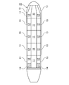
- FIG. 1 is a plan view schematically showing division of a cargo tank of a boat-shaped structure according to a first embodiment of the present invention.
- FIG. 2 is a plan view schematically showing the division of the cargo tank of the boat-shaped structure according to the second embodiment of the present invention.
- FIG. 3 is a plan view schematically showing the division of the cargo tank of the boat-shaped structure according to the third embodiment of the present invention.
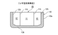
- FIG. 4 is a cross-sectional view schematically showing a U-shaped partition structure of a boat-shaped structure according to a fourth embodiment of the present invention.
- FIG. 5 is a cross-sectional view schematically showing a J-shaped section structure of a boat-shaped structure according to a fourth embodiment of the present invention.
- FIG. 1 is a plan view schematically showing division of a cargo tank of a boat-shaped structure according to a first embodiment of the present invention.
- FIG. 2 is a plan view schematically showing the division of the cargo tank of the boat-shaped structure according to the second embodiment
- FIG. 6 is a cross-sectional view schematically showing a three-compartment structure of a boat-shaped structure according to a fifth embodiment of the present invention.
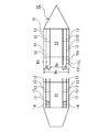
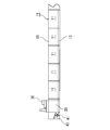
- FIG. 7 is a sectional side view schematically showing the structure of a floating offshore storage structure according to the prior art.
- FIG. 8 is a plan view schematically showing the division of the cargo tank of the floating offshore storage structure according to the prior art.
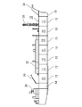
- FIG. 9 is a side sectional view schematically showing the structure of a conventional tanker.
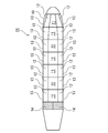
- FIG. 10 is a plan view schematically showing division of a cargo tank of a conventional tanker.
- the boat-shaped structure 1A according to the first embodiment of the present invention is a boat-shaped structure having a common tank structure between the tanker and the floating offshore storage structure.
- the "floating offshore storage structure” here has a cargo tank that stores liquid cargo such as oil and liquefied gas, such as FPSO and FSO, but for self-navigation like a tanker.
- this boat-shaped structure 1A is provided with a center cargo tank 11 and wing cargo tanks 12 on both sides thereof symmetrically with respect to the width direction of the ship, and a ballast tank or void outside the wing cargo tank 12.
- a ship side and a bottom section 13 used as a space are provided. Then, the rows of the ship side and the bottom section 13, the wing cargo tank 12, the center cargo tank 11, the wing cargo tank 12, the ship side and the bottom section 13 are arranged in the ship length direction.
- a slop tank horizontal partition wall 14a is provided at a rear portion of the wing cargo tank 12 at the rearmost portion, and a slop tank 14 (portion indicated by hatching) is provided.
- the slop tank 14 is a tank for temporarily storing the oiled sewage from which the cargo tanks 11 and 12 have been washed and leaving the oily sewage and separating the oily water.
- the oil-separated water is sent to the wastewater treatment facility, and the oil is sent to the oil recovery tank.
- the oily sewage collected in the slop tank 14 is separated, and the lower layer moisture is required.
- wastewater treatment that lowers the oil concentration is discharged and then discharged to the outside of the ship.
- the oil and water mixture cannot be completely separated, and the remaining oil and water mixture is stored and landed at the port of call. .
- Nw is the number of center cargo tanks 11 (FIG. 1). In the configuration of 3), it is configured to be more than 3) Nc. That is, Nw> Nc.
- the number Ns of one side of the ship side and the bottom section 13 is made larger than the number Nc of the center cargo tank 11. That is, Ns> Nc.
- the number Ns of one side of the ship side and the bottom section 13 is equal to or more than the number Nw of one side of the wing cargo tank by the number of tanks or sections excluding the slop tank 14. That is, Ns ⁇ Nw.
- the ship side and the bottom compartment 13 and the wing cargo tank 12 located inside thereof are subdivided to reduce the total volume of the tank that is damaged on the ship side, and the center cargo tank 11 that is difficult to be included in the damage range. Increase the size as much as possible, and reduce the number and area of watertight bulkheads that lead to increased man-hours and costs.
- the number Nw of one side of the wing cargo tank 12 is 1.5 times or more and 2 times or less of the number Nc of the center cargo tank 11 by the number of tanks or the number of compartments excluding the slop tank 14 (1 .5 ⁇ Nc ⁇ Nw ⁇ 2 ⁇ Nc).
- the boat-shaped structure 1B according to the second embodiment of the present invention is different from the boat-shaped structure 1A according to the first embodiment in the side partition horizontal partition wall 13a that separates the ship side and the ship bottom partition 13 with respect to the ship length direction. Is different from the wing cargo tank horizontal partition wall 12a that divides the wing cargo tank 12 in the front-rear direction by a predetermined distance Lt1 and Lt2, but the other configurations are the same.
- the set distances Lt1 and Lt2 are the minimum length Ls of “L (2/3) / 3” or “14.5 m”, which is smaller than Ls, where L is the freeboard length of the boat-shaped structure.
- L the distance between the two wing cargo tank transverse bulkheads 12a because the possibility that the damage on the ship side will remain in one wing cargo tank 12 increases.
- the set distances Lt1 and Lt2 are less than the length Ls, the possibility that the two wing cargo tanks 12 are damaged increases when the damaged portion becomes longer.
- the wing cargo tank 12 adjacent thereto may remain in one section of water. Therefore, the restoring force when the ship-shaped structure 1B is damaged on the ship side can be increased, and the outflow of cargo in the wing cargo tank 12 can be reduced.
- the boat-shaped structure 1C of the third embodiment according to the present invention is different from the boat-shaped structure 1A of the first embodiment only in the following points, and the other configurations are the same.
- the inner side of the ship side skin 10a when the position in the ship width direction of the longitudinal partition wall 11t between the center cargo tank 11 and the wing cargo tank 12 is Bs, the inner side of the ship side skin 10a. Is larger than “20% Bs” and within the range of “30% Bs” or less inside the ship side skin 10a. According to this configuration, there is a possibility that ship side damage may occur in a floating offshore storage structure in which a huge plant is mounted on the upper deck while ensuring sufficient stability at the time of damage necessary as a tanker. The volume of the wing cargo tank 12 can be reduced.
- this longitudinal partition wall 11t may be caused by an emergency such as a ship collision. Since damage may occur, it is not preferable, and if it is larger than “30% Bs”, it is possible to reduce the capacity of the wing cargo tank 12 and to suppress the reduction of the restoring force at the time of damage, and the center cargo tank. This is not preferable because the effect of increasing 11 is reduced.
- the boat-shaped structure 1D of the fourth embodiment according to the present invention is different from the boat-shaped structure 1A of the first embodiment only in the following points, and the other configurations are the same.
- one side (for example, the front side) of the ship side and the bottom section 13 adjacent to the side partition lateral bulkhead 13a that divides the ship side and the bottom section 13 is connected to the lower portion of the center cargo tank 11 and the wing cargo tank 12. It comprises a U-shaped partition structure formed by a U-shaped partition 13A that covers and communicates the lower side portion and the outer side surface portion.
- the other side (for example, the rear) of the ship side and the bottom section 13 adjacent to the side partition side bulkhead 13a is connected to the lower portion of the center cargo tank 11, the lower portion of the wing cargo tank 12, and the outer side surface portion. It is formed with a J-shaped section structure in which two of the J-shaped sections 13B having a ship bottom longitudinal partition wall 13t on the lower side of the center tank 11 are covered.
- the ship side and the bottom section 13 are configured by alternately arranging the U-shaped section structure and the J-shaped section structure in the ship direction.
- the ship side and the bottom section 13 on the port side and the ship side and the bottom section 13 on the starboard side communicate with each other at the bottom of the ship, so that the ballast water in the ship side and the bottom section 13 is damaged due to damage on one side. If seawater flows out or seawater flows into the ship side and the bottom section 13, it reaches both sides. Therefore, the influence on the horizontal inclination of the hull regarding the outflow of ballast water or the inflow of seawater can be reduced.
- the port side and the bottom section 13 on the port side and the ship side and the bottom section 13 on the starboard side are separated and blocked by the ship bottom portion. Even if the ballast water in the inside flows out or the seawater flows into the ship side and the bottom section 13, the ballast water remains only on one side. For this reason, the hull is inclined due to the outflow of ballast water or the inflow of seawater. However, since the outflow amount of the ballast water and the inflow amount of seawater remain only on one side, the influence on the subsidence amount of the hull can be reduced. .
- the U-shaped and J-shaped partition structures can be arranged alternately, the effects of the two-compartment damage due to the collision of the ship, etc. can be reduced. Both the effects on the amount of tilt can be distributed in a balanced manner, and the overall response to damage can be improved.
- the lateral inclination (heel) can be adjusted by adding ballast water to only one of the left and right J-shaped sections 13B. This lateral inclination cannot be adjusted.
- the configuration of the boat-shaped structure 1D according to the fourth embodiment is the same even when applied to the boat-shaped structure 1B according to the second embodiment and the boat-shaped structure 1C according to the third embodiment. An effect can be obtained.
- the boat-shaped structure 1E according to the fifth embodiment of the present invention is different from the boat-shaped structure 1A according to the first embodiment only in the following points, and the other configurations are the same.
- a bottom bottom bulkhead 13 te is provided below the center cargo tank 11 to be separated from the side section 13 C, and a bottom center section 13 D is provided between the bottom bottom partition 13 te of both sides. (Cross-hatched part) is provided, and this ship bottom center section 13D is a section that contains ballast water when used as a tanker, and a section that does not contain ballast water when used as a floating offshore storage structure.
- the configuration of the boat-shaped structure 1E according to the fifth embodiment is the same even when applied to the boat-shaped structure 1B according to the second embodiment and the boat-shaped structure 1C according to the third embodiment. An effect can be obtained.
- the ship-shaped structure design method of the embodiment according to the present invention is the same as that of the ship-shaped structures 1A, 1B, 1C, 1D, and 1E (hereinafter referred to as 1A to 1E) of the first to fifth embodiments.
- the center cargo tank 11 and its both sides are symmetrically used with respect to the width of the ship when designing a ship-shaped structure having a common tank structure between the tanker and the floating offshore storage structure.
- the wing cargo tank 12 is further provided with a ship side and a bottom section 13 used as a ballast tank or void space outside the wing cargo tank 12, and the number of tanks or sections excluding the slop tank 14 is In this method, the number Nw of one side of the wing cargo tank 12 is made larger than the number Nc of the center cargo tank 11.
- the ship-shaped structure should be The side of the wing cargo tank that divides the longitudinal partition wall 12t between the wing cargo tank 12 and the ship side and the bottom section 13 and the front and rear direction of the wing cargo tank 12 is damaged in the ship side and the bottom section 13 of the objects 1A to 1E. Even if the bulkhead 12a is damaged, the number of winkergog tanks 12 is increased, and the capacity per wing cargo tank 12 is reduced, so that the restoring force at the time of ship side damage of the ship-shaped structures 1A to 1E is increased. In addition, the outflow of cargo in the wing cargo tank 12 can be reduced.
- the number Nc of the center cargo tanks 11 is made smaller than the number Nw of one side of the wing cargo tank 12 and is kept at the same number as the tanker of the prior art, leading to an increase in manufacturing man-hours and hull weight. Since the number of center cargo tank horizontal partition walls 11a that divide the center cargo tank 11 in the front-rear direction, that is, the number and area of the watertight partition walls does not increase, it is possible to suppress an increase in cost while maintaining usability as a tanker.
- the number Nc of the center cargo tanks 11 that are not damaged when the ship side is damaged is reduced as much as possible, and the number of wing cargo tanks 12 (2 ⁇ Nw) is increased, thereby suppressing the increase in the horizontal bulkhead that increases the cost. It is possible to make the section arrangement resistant to damage on the ship side.
- it when used as a tanker, while maintaining the usability and cost competitiveness as a tanker, it can be divided into sections that can be used for floating offshore storage structures such as FPSO and FSO. The cost and lead time can be reduced, and when used as a floating offshore storage structure, the floating offshore storage structure can be supplied quickly and inexpensively.
- the ship-shaped structures 1A to 1E satisfying the requirements of both the tanker and the floating offshore storage structure, or the ship-shaped structure 1A to 1E that can be easily changed in design or modified from the tanker to the floating offshore storage structure.
- the number of tanks that increase the cost i.e., the partition arrangement that is particularly resistant to damage on the ship side is planned without increasing the area of the watertight bulkhead separating the tanks as much as possible.
- the floating offshore storage structure while maintaining the ease of use as a tanker and cost competitiveness, it can be used as it is for the floating offshore storage structure, resulting in a reduction in design cost and lead time, which is cheap and quick. Since a floating offshore storage structure can be supplied, it can be used for a large number of tankers and ship-type structures of floating offshore storage structures and a method for designing a ship-shaped structure.
- Hull 10a Ship side skin 11 Center cargo tank 11a Center cargo tank lateral bulkhead 11t Longitudinal bulkhead 12 between center cargo tank and wing cargo tank Wing cargo tank 12a Wing Cargo tank horizontal bulkhead 12t Longitudinal bulkhead 13 between wing cargo tank and ship side and bottom section 13 Ship side and bottom section 13A U-shaped section 13B J-shaped section 13C Side-side section 13D Ship bottom center section 13a Side partition lateral bulkhead 13t, 13te Longitudinal bulkhead 14 bottom slop tank 14a Horizontal bulkhead for slop tank
Landscapes
- Chemical & Material Sciences (AREA)
- Engineering & Computer Science (AREA)
- Combustion & Propulsion (AREA)
- Mechanical Engineering (AREA)
- Ocean & Marine Engineering (AREA)
- Filling Or Discharging Of Gas Storage Vessels (AREA)
- Health & Medical Sciences (AREA)
- Public Health (AREA)
- Revetment (AREA)
Abstract
Description
10 船体
10a 船側外板
11 センターカーゴタンク
11a センターカーゴタンク用横隔壁
11t センターカーゴタンクとウイングカーゴタンクとの間の縦通隔壁
12 ウイングカーゴタンク
12a ウイングカーゴタンク用横隔壁
12t ウイングカーゴタンクと船側及び船底区画の間の縦通隔壁
13 船側及び船底区画
13A U字型区画
13B J字型区画
13C 舷側側の区画
13D 船底中央区画
13a サイド区画用横隔壁
13t、13te 船底縦通隔壁
14 スロップタンク
14a スロップタンク用横隔壁
Claims (9)
- タンク構造を有する船形構造物であって、
船幅方向に関して左右対称に、センターカーゴタンクとその両側にウイングカーゴタンクを備え、該ウイングカーゴタンクの外側に、バラストタンク若しくはボイドスペースとして使用される船側及び船底区画を備えると共に、
スロップタンクを除いたタンクまたは区画の数で、前記ウイングカーゴタンクの片舷の数を、前記センターカーゴタンクの数よりも多くすることを特徴とする船形構造物。 - 船長方向に関して、前記船側及び船底区画を区分するサイド区画用横隔壁を、前記ウイングカーゴタンクの前後方向を区分するウイングカーゴタンク用横隔壁に対して、予め設定した距離だけずらして設けることを特徴とする請求項1記載の船形構造物。
- 前記船側及び船底区画の片舷の数を前記センターカーゴタンクの数よりも多くすることを特徴とする請求項1又は2に記載の船形構造物。
- 前記船側及び船底区画の片舷の数を、前記スロップタンクを除いたタンクまたは区画の数で、前記ウイングカーゴタンクの片舷の数以上とすることを特徴とする請求項1~3のいずれか1項に記載の船形構造物。
- 前記スロップタンクを除いたタンクの数または区画の数で、前記ウイングカーゴタンクの片舷の数を前記センターカーゴタンクの数の1.5倍以上かつ2倍以下とすることを特徴とする請求項1~4のいずれか1項に記載の船形構造物。
- 前記センターカーゴタンクと前記ウイングカーゴタンクとの間の縦通隔壁の船幅方向の位置を、その船長方向における位置での船幅をBsとした場合に、船側外板よりも内側に「20%Bs」よりも大きく、かつ、船側外板よりも内側に「30%Bs」以下の範囲内とすることを特徴とする請求項1~5のいずれか1項に記載の船形構造物。
- 船長方向に関して、前記船側及び船底区画を区分するサイド区画用横隔壁に隣接する船側及び船底区画の一方を、前記センターカーゴタンクの下側部分と前記ウイングカーゴタンクの下側部分と外側の側面部分を連通して覆うU字型区画で形成されるU字型区画構造と、他方を前記センターカーゴタンクの下側部分と前記ウイングカーゴタンクの下側部分と外側の側面部分を連通して覆うと共に前記センタータンクの下側に船底縦通隔壁を有するJ字型区画の2つが対となるJ字型区画構造とで形成して、
船長方向に関して、前記船側及び船底区画を、前記U字型区画構造と前記J字型区画構造を交互に配置して構成することを特徴とする請求項1~6のいずれか1項に記載の船形構造物。 - 前記船側及び船底区画において、前記センターカーゴタンクの下側で前記船底縦通隔壁の間に船底中央区画を設け、タンカーとして使用するときは前記船底中央区画をバラスト水を入れる区画とし、浮体式洋上貯蔵構造物として使用するときは前記船底中央区画をバラスト水を入れない区画とすることを特徴とする請求項1~6のいずれか1項に船形構造物。
- タンク構造を有する船形構造物の設計方法であって、
船幅方向に関して左右対称に、センターカーゴタンクとその両側にウイングカーゴタンクを備え、さらに、該ウイングカーゴタンクの外側に、バラストタンク若しくはボイドスペースとして使用される船側及び船底区画を備えると共に、
スロップタンクを除いたタンクまたは区画の数で、前記ウイングカーゴタンクの片舷の数を前記センターカーゴタンクの数よりも多くすることを特徴とする船形構造物の設計方法。
Priority Applications (4)
| Application Number | Priority Date | Filing Date | Title |
|---|---|---|---|
| KR1020157023798A KR102169903B1 (ko) | 2013-05-15 | 2014-04-28 | 선형 구조물 |
| SG11201509326TA SG11201509326TA (en) | 2013-05-15 | 2014-04-28 | Ship-type structure and method for designing ship-type structure |
| CN201480027506.XA CN105209334B (zh) | 2013-05-15 | 2014-04-28 | 船形结构物和船形结构物的设计方法 |
| BR112015027056A BR112015027056A2 (pt) | 2013-05-15 | 2014-04-28 | estrutura tipo navio e método para projetar a estrutura navicular |
Applications Claiming Priority (2)
| Application Number | Priority Date | Filing Date | Title |
|---|---|---|---|
| JP2013-102697 | 2013-05-15 | ||
| JP2013102697A JP6169412B2 (ja) | 2013-05-15 | 2013-05-15 | 船形構造物及び船形構造物の設計方法 |
Publications (1)
| Publication Number | Publication Date |
|---|---|
| WO2014185259A1 true WO2014185259A1 (ja) | 2014-11-20 |
Family
ID=51898239
Family Applications (1)
| Application Number | Title | Priority Date | Filing Date |
|---|---|---|---|
| PCT/JP2014/061834 Ceased WO2014185259A1 (ja) | 2013-05-15 | 2014-04-28 | 船形構造物及び船形構造物の設計方法 |
Country Status (6)
| Country | Link |
|---|---|
| JP (1) | JP6169412B2 (ja) |
| KR (1) | KR102169903B1 (ja) |
| CN (1) | CN105209334B (ja) |
| BR (1) | BR112015027056A2 (ja) |
| SG (1) | SG11201509326TA (ja) |
| WO (1) | WO2014185259A1 (ja) |
Cited By (6)
| Publication number | Priority date | Publication date | Assignee | Title |
|---|---|---|---|---|
| CN113697031A (zh) * | 2021-09-10 | 2021-11-26 | 肖昌美 | 一种多用途浅吃水直通甲板船型 |
| CN113895586A (zh) * | 2021-10-27 | 2022-01-07 | 沪东中华造船(集团)有限公司 | 一种薄膜型lng船货舱区分段划分方法 |
| CN114291201A (zh) * | 2021-12-01 | 2022-04-08 | 中国船舶工业集团公司第七0八研究所 | 一种超大型原油船无制荡舱壁的货舱结构 |
| WO2024037964A1 (en) * | 2022-08-17 | 2024-02-22 | Single Buoy Moorings Inc. | Floating structure |
| WO2024073488A1 (en) * | 2022-09-29 | 2024-04-04 | Puneet Sharma | Floating production storage and offloading vessel for production of hydrogen and ammonia |
| CN118722996A (zh) * | 2024-07-24 | 2024-10-01 | 沪东中华造船(集团)有限公司 | 一种27.1万立方米薄膜型lng船货舱底层分段划分方法 |
Families Citing this family (11)
| Publication number | Priority date | Publication date | Assignee | Title |
|---|---|---|---|---|
| JP2017114264A (ja) * | 2015-12-24 | 2017-06-29 | 三井海洋開発株式会社 | 浮体設備の建造方法、及び、浮体設備の浮体構造体 |
| CN105836051A (zh) * | 2016-05-25 | 2016-08-10 | 中国海洋石油总公司 | 一种适用于浮式生产储油装置的折线型舱壁 |
| SE542010C2 (en) * | 2016-10-06 | 2020-02-11 | Bassoe Tech Ab | Ship |
| JP6737431B2 (ja) * | 2016-10-11 | 2020-08-12 | 三井E&S造船株式会社 | 液化ガス運搬船 |
| KR101903103B1 (ko) | 2016-10-27 | 2018-10-01 | 삼성중공업 주식회사 | 힌지 타입 구획 벽체가 설치된 화물유 저장탱크를 구비한 해양구조물 및 손상공간 감소 방법 |
| JP7088452B2 (ja) * | 2017-05-31 | 2022-06-21 | 三井E&S造船株式会社 | 洋上浮体構造物 |
| JP2019026083A (ja) * | 2017-07-31 | 2019-02-21 | 三井E&S造船株式会社 | 船形構造物 |
| CN108945287B (zh) * | 2018-07-06 | 2021-02-12 | 中国船舶工业集团公司第七0八研究所 | 一种无制荡舱壁无横撑超大型原油船 |
| KR102340138B1 (ko) * | 2020-08-24 | 2021-12-16 | 현대중공업 주식회사 | 선박 |
| KR20220081889A (ko) * | 2020-12-09 | 2022-06-16 | 대우조선해양 주식회사 | 화물창 구조 및 상기 화물창 구조를 갖는 초대형 원유 운반선 |
| CN114348170A (zh) * | 2022-01-28 | 2022-04-15 | 广船国际有限公司 | 一种保护舱壁 |
Citations (7)
| Publication number | Priority date | Publication date | Assignee | Title |
|---|---|---|---|---|
| JPS60174385A (ja) * | 1984-02-17 | 1985-09-07 | Hitachi Zosen Corp | タンカ− |
| JPH072165A (ja) * | 1993-02-26 | 1995-01-06 | Nkk Corp | オイルタンカーの船体構造 |
| JPH11115875A (ja) * | 1997-10-14 | 1999-04-27 | Ishikawajima Harima Heavy Ind Co Ltd | 油槽船 |
| JP2000142560A (ja) * | 1998-11-13 | 2000-05-23 | Nippon Marine Kk | 鉱石・硫酸運搬船 |
| JP2003081177A (ja) * | 2001-08-31 | 2003-03-19 | Joseph Wei Ryungu Haa | オイルおよび清水タンカーの船体構造 |
| US20110192339A1 (en) * | 2008-10-09 | 2011-08-11 | Keppel Offshore & Marine Technology Centre Pte Ltd | Hull conversion of existing vessels for tank integration |
| WO2013024835A1 (ja) * | 2011-08-13 | 2013-02-21 | Morimoto Nobuyoshi | Lng船 |
Family Cites Families (1)
| Publication number | Priority date | Publication date | Assignee | Title |
|---|---|---|---|---|
| US6921556B2 (en) | 2002-04-12 | 2005-07-26 | Asm Japan K.K. | Method of film deposition using single-wafer-processing type CVD |
-
2013
- 2013-05-15 JP JP2013102697A patent/JP6169412B2/ja active Active
-
2014
- 2014-04-28 KR KR1020157023798A patent/KR102169903B1/ko active Active
- 2014-04-28 CN CN201480027506.XA patent/CN105209334B/zh active Active
- 2014-04-28 BR BR112015027056A patent/BR112015027056A2/pt not_active IP Right Cessation
- 2014-04-28 SG SG11201509326TA patent/SG11201509326TA/en unknown
- 2014-04-28 WO PCT/JP2014/061834 patent/WO2014185259A1/ja not_active Ceased
Patent Citations (7)
| Publication number | Priority date | Publication date | Assignee | Title |
|---|---|---|---|---|
| JPS60174385A (ja) * | 1984-02-17 | 1985-09-07 | Hitachi Zosen Corp | タンカ− |
| JPH072165A (ja) * | 1993-02-26 | 1995-01-06 | Nkk Corp | オイルタンカーの船体構造 |
| JPH11115875A (ja) * | 1997-10-14 | 1999-04-27 | Ishikawajima Harima Heavy Ind Co Ltd | 油槽船 |
| JP2000142560A (ja) * | 1998-11-13 | 2000-05-23 | Nippon Marine Kk | 鉱石・硫酸運搬船 |
| JP2003081177A (ja) * | 2001-08-31 | 2003-03-19 | Joseph Wei Ryungu Haa | オイルおよび清水タンカーの船体構造 |
| US20110192339A1 (en) * | 2008-10-09 | 2011-08-11 | Keppel Offshore & Marine Technology Centre Pte Ltd | Hull conversion of existing vessels for tank integration |
| WO2013024835A1 (ja) * | 2011-08-13 | 2013-02-21 | Morimoto Nobuyoshi | Lng船 |
Cited By (7)
| Publication number | Priority date | Publication date | Assignee | Title |
|---|---|---|---|---|
| CN113697031A (zh) * | 2021-09-10 | 2021-11-26 | 肖昌美 | 一种多用途浅吃水直通甲板船型 |
| CN113697031B (zh) * | 2021-09-10 | 2022-07-01 | 肖昌美 | 一种多用途浅吃水直通甲板船型 |
| CN113895586A (zh) * | 2021-10-27 | 2022-01-07 | 沪东中华造船(集团)有限公司 | 一种薄膜型lng船货舱区分段划分方法 |
| CN114291201A (zh) * | 2021-12-01 | 2022-04-08 | 中国船舶工业集团公司第七0八研究所 | 一种超大型原油船无制荡舱壁的货舱结构 |
| WO2024037964A1 (en) * | 2022-08-17 | 2024-02-22 | Single Buoy Moorings Inc. | Floating structure |
| WO2024073488A1 (en) * | 2022-09-29 | 2024-04-04 | Puneet Sharma | Floating production storage and offloading vessel for production of hydrogen and ammonia |
| CN118722996A (zh) * | 2024-07-24 | 2024-10-01 | 沪东中华造船(集团)有限公司 | 一种27.1万立方米薄膜型lng船货舱底层分段划分方法 |
Also Published As
| Publication number | Publication date |
|---|---|
| KR102169903B1 (ko) | 2020-10-26 |
| SG11201509326TA (en) | 2015-12-30 |
| BR112015027056A2 (pt) | 2017-07-25 |
| CN105209334A (zh) | 2015-12-30 |
| CN105209334B (zh) | 2018-01-09 |
| JP6169412B2 (ja) | 2017-07-26 |
| KR20160009010A (ko) | 2016-01-25 |
| JP2014223819A (ja) | 2014-12-04 |
Similar Documents
| Publication | Publication Date | Title |
|---|---|---|
| JP6169412B2 (ja) | 船形構造物及び船形構造物の設計方法 | |
| CN103764494B (zh) | Lng船 | |
| Bertram et al. | Ship design for efficiency and economy | |
| CN105813938B (zh) | 船型结构物 | |
| Muckle | Naval architecture for marine engineers | |
| CN109863080B (zh) | 液化气运输船 | |
| JP2018030467A (ja) | バラ積み船 | |
| Muckle et al. | Muckle's naval architecture | |
| CN104494793A (zh) | 一种基于新型压载舱的万箱以上超大型集装箱船 | |
| Sahoo | Principles of marine vessel design: concepts and design fundamentals of Sea going vessels | |
| House | The Ship | |
| JP5059725B2 (ja) | 自動車運搬船 | |
| KR101263247B1 (ko) | 이동 항구 | |
| Cheng et al. | Improvement of ship safety through stability research and innovations | |
| Curley | The Complete History of Ships and Boats: From Sails and Oars to Nuclear-Powered Vessels | |
| Samson et al. | Damage Stability Behavior Analysis of a Cruise Liner Using Computer-Aided Design (CAD) | |
| Hirdaris | Lecture Notes on Basic Naval Architecture | |
| Aarnio | Stability | |
| Antoniadis | Preliminary design of Ro-Pax ferry | |
| Lira et al. | P-67: Review of Dry Transportation of FLNG’s/FSRU’s/FPSO’s | |
| DeNucci et al. | Riding the Chine: A Case Study in Commercial Fishing Vessel Stability | |
| Kurniawan et al. | English in Maritime Vocation | |
| Roh et al. | General Arrangement Design | |
| McGowan et al. | Has Stability Delayed the Delivery of Your Tug? | |
| Santoso et al. | Stability Study Of High-Speed Passenger Ship: A Case Study Of KMP Marine Hawk II |
Legal Events
| Date | Code | Title | Description |
|---|---|---|---|
| 121 | Ep: the epo has been informed by wipo that ep was designated in this application |
Ref document number: 14798305 Country of ref document: EP Kind code of ref document: A1 |
|
| ENP | Entry into the national phase |
Ref document number: 20157023798 Country of ref document: KR Kind code of ref document: A |
|
| NENP | Non-entry into the national phase |
Ref country code: DE |
|
| REG | Reference to national code |
Ref country code: BR Ref legal event code: B01A Ref document number: 112015027056 Country of ref document: BR |
|
| 122 | Ep: pct application non-entry in european phase |
Ref document number: 14798305 Country of ref document: EP Kind code of ref document: A1 |
|
| ENP | Entry into the national phase |
Ref document number: 112015027056 Country of ref document: BR Kind code of ref document: A2 Effective date: 20151026 |