WO2014181590A1 - 管接続装置 - Google Patents
管接続装置 Download PDFInfo
- Publication number
- WO2014181590A1 WO2014181590A1 PCT/JP2014/058002 JP2014058002W WO2014181590A1 WO 2014181590 A1 WO2014181590 A1 WO 2014181590A1 JP 2014058002 W JP2014058002 W JP 2014058002W WO 2014181590 A1 WO2014181590 A1 WO 2014181590A1
- Authority
- WO
- WIPO (PCT)
- Prior art keywords
- tube
- outer peripheral
- diameter
- inner ring
- inner peripheral
- Prior art date
Links
Images


Classifications
-
- F—MECHANICAL ENGINEERING; LIGHTING; HEATING; WEAPONS; BLASTING
- F16—ENGINEERING ELEMENTS AND UNITS; GENERAL MEASURES FOR PRODUCING AND MAINTAINING EFFECTIVE FUNCTIONING OF MACHINES OR INSTALLATIONS; THERMAL INSULATION IN GENERAL
- F16L—PIPES; JOINTS OR FITTINGS FOR PIPES; SUPPORTS FOR PIPES, CABLES OR PROTECTIVE TUBING; MEANS FOR THERMAL INSULATION IN GENERAL
- F16L13/00—Non-disconnectible pipe-joints, e.g. soldered, adhesive or caulked joints
- F16L13/14—Non-disconnectible pipe-joints, e.g. soldered, adhesive or caulked joints made by plastically deforming the material of the pipe, e.g. by flanging, rolling
- F16L13/147—Non-disconnectible pipe-joints, e.g. soldered, adhesive or caulked joints made by plastically deforming the material of the pipe, e.g. by flanging, rolling by radially expanding the inner part
-
- F—MECHANICAL ENGINEERING; LIGHTING; HEATING; WEAPONS; BLASTING
- F16—ENGINEERING ELEMENTS AND UNITS; GENERAL MEASURES FOR PRODUCING AND MAINTAINING EFFECTIVE FUNCTIONING OF MACHINES OR INSTALLATIONS; THERMAL INSULATION IN GENERAL
- F16L—PIPES; JOINTS OR FITTINGS FOR PIPES; SUPPORTS FOR PIPES, CABLES OR PROTECTIVE TUBING; MEANS FOR THERMAL INSULATION IN GENERAL
- F16L15/00—Screw-threaded joints; Forms of screw-threads for such joints
- F16L15/08—Screw-threaded joints; Forms of screw-threads for such joints with supplementary elements
-
- F—MECHANICAL ENGINEERING; LIGHTING; HEATING; WEAPONS; BLASTING
- F16—ENGINEERING ELEMENTS AND UNITS; GENERAL MEASURES FOR PRODUCING AND MAINTAINING EFFECTIVE FUNCTIONING OF MACHINES OR INSTALLATIONS; THERMAL INSULATION IN GENERAL
- F16L—PIPES; JOINTS OR FITTINGS FOR PIPES; SUPPORTS FOR PIPES, CABLES OR PROTECTIVE TUBING; MEANS FOR THERMAL INSULATION IN GENERAL
- F16L19/00—Joints in which sealing surfaces are pressed together by means of a member, e.g. a swivel nut, screwed on or into one of the joint parts
- F16L19/02—Pipe ends provided with collars or flanges, integral with the pipe or not, pressed together by a screwed member
- F16L19/025—Pipe ends provided with collars or flanges, integral with the pipe or not, pressed together by a screwed member the pipe ends having integral collars or flanges
- F16L19/028—Pipe ends provided with collars or flanges, integral with the pipe or not, pressed together by a screwed member the pipe ends having integral collars or flanges the collars or flanges being obtained by deformation of the pipe wall
-
- F—MECHANICAL ENGINEERING; LIGHTING; HEATING; WEAPONS; BLASTING
- F16—ENGINEERING ELEMENTS AND UNITS; GENERAL MEASURES FOR PRODUCING AND MAINTAINING EFFECTIVE FUNCTIONING OF MACHINES OR INSTALLATIONS; THERMAL INSULATION IN GENERAL
- F16L—PIPES; JOINTS OR FITTINGS FOR PIPES; SUPPORTS FOR PIPES, CABLES OR PROTECTIVE TUBING; MEANS FOR THERMAL INSULATION IN GENERAL
- F16L33/00—Arrangements for connecting hoses to rigid members; Rigid hose connectors, i.e. single members engaging both hoses
- F16L33/22—Arrangements for connecting hoses to rigid members; Rigid hose connectors, i.e. single members engaging both hoses with means not mentioned in the preceding groups for gripping the hose between inner and outer parts
- F16L33/223—Arrangements for connecting hoses to rigid members; Rigid hose connectors, i.e. single members engaging both hoses with means not mentioned in the preceding groups for gripping the hose between inner and outer parts the sealing surfaces being pressed together by means of a member, e.g. a swivel nut, screwed on or into one of the joint parts
-
- F—MECHANICAL ENGINEERING; LIGHTING; HEATING; WEAPONS; BLASTING
- F16—ENGINEERING ELEMENTS AND UNITS; GENERAL MEASURES FOR PRODUCING AND MAINTAINING EFFECTIVE FUNCTIONING OF MACHINES OR INSTALLATIONS; THERMAL INSULATION IN GENERAL
- F16L—PIPES; JOINTS OR FITTINGS FOR PIPES; SUPPORTS FOR PIPES, CABLES OR PROTECTIVE TUBING; MEANS FOR THERMAL INSULATION IN GENERAL
- F16L47/00—Connecting arrangements or other fittings specially adapted to be made of plastics or to be used with pipes made of plastics
- F16L47/04—Connecting arrangements or other fittings specially adapted to be made of plastics or to be used with pipes made of plastics with a swivel nut or collar engaging the pipe
- F16L47/041—Connecting arrangements or other fittings specially adapted to be made of plastics or to be used with pipes made of plastics with a swivel nut or collar engaging the pipe the plastic pipe end being flared either before or during the making of the connection
Definitions
- the present invention relates to a pipe connection device using an inner ring, and more specifically, high-purity liquid and ultrapure water handled in manufacturing processes in various technical fields such as semiconductor manufacturing, medical / pharmaceutical manufacturing, food processing, and chemical industry.
- the present invention relates to a pipe connection device suitable for the above pipes.
- a pipe connecting device using an inner ring is for sealing having a cylindrical threaded portion protruding from a pipe joint main body or a fluid device in a state where a male screw is formed on the outer periphery, and an annular large-diameter portion protruding outward from the diameter.
- the inner ring and a union nut formed with a female screw that is screwed onto the male screw are known.
- Patent Document 1 the one disclosed in Patent Document 1 is known.
- a raised inner ring for fixing a tube, and a union nut formed with a female screw that is screwed into the male screw are provided.
- the inner ring is press-fitted into the end portion of the tube from the opening of the tube, and the end portion of the tube is expanded and deformed by the annular large diameter portion.
- the tube with the inner ring whose diameter has been deformed is inserted into the cylindrical threaded portion.
- the female screw of the union nut is screwed into the male screw of the cylindrical screwing portion.
- the union nut is tightened and screwed, and the tube is connected by pressing the tube with the inner ring in the axial direction with this union nut.
- the object of the present invention is to improve the pipe connection so that it can be repeatedly used more than before, while maintaining good sealing performance by revising the structure once again in the type using the inner ring.
- the point is to provide a device.
- the tapered outer peripheral diameter-enlarging surface 3a that press-fits into the end portion 4C of the fluid transfer tube 4 from the distal end and expands the inner peripheral portion of the end portion 4C of the tube 4 is the distal end.
- An inner ring 3 having an outer peripheral portion 3G formed on the inner peripheral portion 3w and an inner peripheral portion 3w constituting the fluid transfer channel;
- a pipe joint body 1 or a fluid device 1 having a cylindrical threaded portion 1A in which a male screw 7 is formed on the outer peripheral side;
- a union nut 2 formed with a female screw 13 to be screwed into the male screw 7 of the cylindrical screw part 1A,
- the inner ring 3 is inserted into the cylindrical threaded portion 1A in a state where the inner peripheral portion of the end portion 4C of the tube 4 is expanded, and the outer peripheral expanded surface 3a is formed by the cylindrical screw.
- a pressing portion 12b that presses the tube 4 between the union nut 2 and the outer peripheral enlarged surface 3a is inclined in the same direction as the outer peripheral enlarged surface 3a with respect to the axis Y of the cylindrical threaded portion 1A. It is formed on the inclined inner peripheral surface.
- the invention according to claim 2 is the pipe connection device according to claim 1,
- the outer peripheral diameter-enlarging surface 3a is a state in which the diameter of the inner diameter part of the end part 4C of the tube 4 to be expanded is only expanded to the maximum, and the end part 4C of the tube that appears at that time is shown. It is characterized in that it is formed in a state that has a larger diameter and a convex curved surface than the inner peripherally enlarged diameter surface 4u of the naturally tapered inner peripheral portion.
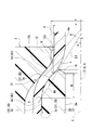
- the invention according to claim 3 is the pipe connection device according to claim 1, An angle ⁇ of the inclined inner peripheral surface 12b with respect to the axis Y is set to be larger than an angle ⁇ of the outer peripheral enlarged diameter surface 3a with respect to the axis Y.
- the minimum diameter r of the pressing portion 12b is the minimum diameter n of the press-fitting fitting portion M between the outer peripheral enlarged surface 3a and the tube 4. It is characterized by being set to be equal to or greater than.
- the invention according to claim 5 is the pipe connection device according to claim 1, Back seal portions S2 and S3 are formed by pressure contact between the seal element portion y formed on the proximal end side of the inner ring 3 and the seal component portion k provided in the pipe joint body 1 or the fluid device 1. It is characterized by that.
- the pressing portion pushes the portion fitted on the outer peripheral enlarged surface at the end of the tube in the axial direction.
- the pressing portion is an inclined inner peripheral surface that is inclined in the same direction as the outer peripheral diameter-enlarged surface, and has a configuration in which the tube is pressed with a wide surface. This can clearly reduce the pressure (surface pressure) that pushes the tube as compared with the conventional configuration in which it is pressed locally with a sharp corner, and hence the creep phenomenon can be reduced.
- the tube connection device that has a structure in which the tube that is forcibly externally fitted to the inner ring is fitted inside the fitting body has good sealing performance, the union nut pressing part is sharpened to bite into the tube. It has been found that there is no clear difference in sealing performance between the conventional configuration in which the tube is pushed in such a manner and the present configuration in which the tube is entirely pressed with a wide inclined inner peripheral surface. Therefore, according to the configuration of claim 1 of the present invention, which is devised to avoid stress concentration and reduce the surface pressure, it becomes possible to reduce deformation and creep of the tube, so that the number of repeated use can be clearly increased. It becomes possible.
- a pipe connection device can be provided.
- the angle with respect to the axis of the inclined inner peripheral surface is set to be larger than the angle with respect to the axis of the outer peripheral expanded surface.
- the portion of the tube that is externally fitted to the inclined inner peripheral surface is more compressed in the thickness direction of the tube as it moves closer to the opposite side of the pipe joint body in the axial direction. As the amount of compression of the tube increases toward the smaller diameter side, a wedge action occurs, and the tube retaining effect can be further enhanced.
- the minimum diameter of the inclined inner peripheral surface is set to be equal to or larger than the minimum diameter of the press-fitting fitting portion between the outer peripheral expanded surface and the tube. It is possible to eliminate waste of pressing the portion where the surface and the tube end portion are not in close contact with the union nut, and it is possible to efficiently perform screw advancement by tightening the union nut without applying excessive pressing force. Therefore, the union nut can be tightened more lightly than before, and the workability can be improved.
- the fifth aspect of the present invention it is possible to form the back seal portion by pressure contact between the seal element portion formed on the proximal end side of the inner ring and the seal constituent portion provided in the pipe joint body. Therefore, the sealing performance is sufficiently provided. As a result, in the configuration of the portion where the tube is pressed by the pressing portion, it is possible to achieve a design in which a focus is focused by preventing the tube from coming off, or an effect that the sealing performance is further increased.
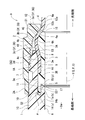
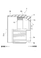
- tightening state (Embodiment 1) Side view of partly cutout showing inner ring Side view of partly cutout showing union nut Side view of partially cut-out showing the fitting body
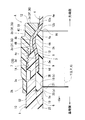
- Sectional drawing of the principal part which shows the pipe connection apparatus of another structure (Embodiment 2) (A) expands and deforms the end of the tube using a cylinder formed with the same diameter as the maximum diameter portion of the inner ring, and expands the inner circumference of the natural constriction of the inner circumference of the end of the tube that appears there.
- the side (or direction) away from the main body 1 in the direction of the axis Y, and the “base end side” and “base end” are the side (or direction) where the tube 4 approaches the pipe joint main body 1 in the direction of the axis Y. Define to point.
- the pipe connection device A is composed of a pipe joint that connects tubes, and includes a pipe joint main body 1, a union nut 2, and an inner ring 3, and the inner ring main body 3 A is connected to the tube 4.
- the tube 4 is connected in communication in a state of being press-fitted into the end 4C.
- the pipe joint body 1, the union nut 2, the inner ring 3, and the tube 4 are all made of a resin such as a fluororesin (eg, PTFE, PFA, ETFE, CTFE, ECTFE, etc.) having excellent heat resistance and chemical resistance.
- a fluororesin eg, PTFE, PFA, ETFE, CTFE, ECTFE, etc.
- the pipe joint main body 1, the inner ring 3, and the tube 4 are comprised with the said fluororesin, in the union nut 2, you may form with resin, such as polyamide, a polypropylene, and polyethylene.
- resin such as polyamide, a polypropylene, and polyethylene.
- all of the pipe joint main body 1, the union nut 2, the inner ring 3, and the tube 4 can be formed of a resin such as polyamide, polypropylene, or polyethylene.
- the pipe joint body 1 includes a cylindrical body 1 ⁇ / b> C, a cylindrical threaded portion 1 ⁇ / b> A provided on the distal end side in the axis Y direction, and a cylindrical threaded portion 1 ⁇ / b> A. It has a cylindrical structure having a small-diameter cylindrical portion 1a formed on the inner diameter side on the proximal end side and an inner peripheral surface 6 constituting the internal flow path 6w. Although illustration is omitted, for example, the base 1C of the body portion 1C also has a cylindrical threaded portion 1A and a small-diameter cylindrical portion 1a, and is formed into a component that is symmetrical in the axial direction.
- a male screw 7 is formed on the cylindrical threaded portion 1 ⁇ / b> A from the outer periphery of the distal end portion toward the proximal end side, and an inner peripheral surface 8 is formed on the inner periphery of the distal end portion, and the proximal end of the inner peripheral surface 8 is formed.
- a linear inner peripheral surface 9 having a constant diameter is formed on the side.
- a linear outer peripheral surface 10 having a constant diameter is formed on the outer diameter side of the small diameter cylindrical portion 1a.
- a tip-end portion on the inner diameter side of the small-diameter cylindrical portion 1a is formed with an inclined inner peripheral surface 5 having a diameter that gradually increases as the tip approaches the distal end of the small-diameter cylindrical portion 1a.
- a cylindrical annular groove m is formed between the outer peripheral surface 10 of the small diameter cylindrical portion 1a and the inner peripheral surface 9 of the cylindrical screwing portion 1A.
- the union nut 2 is made of a resin nut, and has a female screw 13 screwed into the male screw 7 of the cylindrical screwing portion 1 ⁇ / b> A at its inner peripheral portion, and a tip than the female screw 13. And an annular flange 12 that is located on the side and projects to the inside of the diameter.
- the inner diameter portion of the flange portion 12 is set to an inner peripheral surface 12a having a diameter slightly larger than the outer diameter of the tube 4 so that the tube 4 can be inserted.
- the proximal end side of the flange portion 12 is configured as a pressing portion 12b that pushes the outer peripheral surface of the distal end side of the end portion 4C of the tube 4 into which the inner ring main body 3A is press-fitted in the axial center Q direction of the union nut 2.
- six cut flat portions 2 a are formed so as to have a substantially hexagonal shape when viewed in the direction of the axial center Q and can be hooked with a spanner (wrench).
- the pressing portion 12b is formed on an inclined inner peripheral surface that expands so that its diameter increases as it approaches the female screw 13 side (to the proximal end side) in the axial center Q direction. More specifically, the pressing portion 12b of the union nut 2 that sandwiches and presses the tube 4 with the outer circumferential enlarged surface 3a of the inner ring 3 is inclined with respect to the axis Q in the same direction as the outer circumferential enlarged surface 3a. It is formed on the peripheral surface.
- the union nut 2 is screwed by screwing the female screw 13 to the male screw 7 of the cylindrical screwing portion 1A, so that the pressing portion 12b has an axial center Q on the outer peripheral surface on the distal end side of the end portion 4C of the tube 4. It will push in the direction.
- the inner peripheral surface 12a of the flange portion 12 has a constant inner diameter, but may be formed on a tapered inner peripheral surface where the inner diameter gradually increases as the distance from the female screw 13 increases.
- the inner ring 3 includes an inner ring main body 3A that is press-fitted into an end 4C of the tube 4 from the opening of the tube 4, and a tube 4 on the proximal end side of the inner ring main body 3A. It is comprised in the cylindrical body which has the fitting cylinder part 3B which protrudes from this opening
- the inner ring main body 3A and each inner peripheral portion 3w of the fitting cylinder portion 3B are formed with a constant diameter and constitute a fluid flow passage.
- An enlarged diameter portion 3f is formed on the distal end side of the outer peripheral portion 3G of the inner ring main body 3A, and a tapered outer peripheral enlarged surface 3a is formed on the distal end side of the enlarged diameter portion 3f.
- an outer peripheral portion 3c On the proximal end side of the diameter-enlarged portion 3f, an outer peripheral portion 3c having a base diameter that decreases in diameter toward the base end side is formed. Between the surface 3a, the largest diameter part 3b which is a part with the largest diameter is formed.
- a barrel outer peripheral portion (cylinder outer peripheral surface) 3d having a constant outer diameter is formed on the proximal end side of the outer peripheral portion 3c.
- the maximum diameter portion 3b of the inner ring 3 is described as a structure having a certain length in the direction of the axis P, but the maximum diameter portion 3b is immediately tapered and has an outer peripheral enlarged surface. Even if the structure corresponds to the boundary that changes to 3a and the outer peripheral portion 3c of the base, there is no technical problem.
- the tapered outer peripheral enlarged surface 3a of the enlarged diameter portion 3f is formed into a convex curved surface that is convex outward in the radial direction, and the maximum diameter portion 3b is formed on the proximal end side of the tapered outer peripheral enlarged surface 3a. Is formed, and the tapered outer peripherally enlarged surface 3a and the maximum diameter portion 3b are press-fitted into the end 4C of the tube 4, whereby the end 4C of the tube 4 is expanded and deformed.
- a base-cut-shaped deformation preventing portion 16 whose diameter decreases as it proceeds toward the proximal end side of the axis P of the inner ring main body 3A is formed. Yes.
- the deformation preventing portion 16 after the tapered outer diameter-enlarging surface 3 a is press-fitted into the end portion 4 ⁇ / b> C of the tube 4, the distal end portion of the diameter-expanding portion 3 f is reduced in diameter in the radially inward direction (fluid flow passage side).
- the deformation preventing portion 16 can prevent or suppress the distal end side of the outer peripheral enlarged diameter surface 3a from further deforming and projecting in the radially inward direction (fluid flow path side) at the momentum and speed of the fluid flow.
- the fitting cylinder portion 3B includes a protruding cylindrical portion 14 that is press-fitted into the annular groove m of the pipe joint main body 1, and an annular small protruding portion 15 that is provided on the radially inner side of the protruding cylindrical portion 14 and has an inclined outer peripheral surface 11. Is formed. At the base end portion of the annular small protrusion 15, a tapered cut-shaped deformation preventing portion 17 whose diameter decreases as it moves toward the distal end side of the axis P of the inner ring main body 3 ⁇ / b> A is formed.
- the tube 4 has an end portion 4 ⁇ / b> C that is a base end portion thereof press-fitted and fitted into the inner ring main body 3 ⁇ / b> A.
- the constricted pressure contact portion 4a that is in pressure contact with the conical outer diameter expansion surface 3a, the maximum diameter expansion contact portion 4b that is in pressure contact with the maximum diameter portion 3b, and the base constriction outer peripheral portion 3c are pressure contacted.
- An expanded pressure contact portion 4c and a body pressure contact portion 4d pressed against the body outer peripheral portion 3d are formed at the end portion 4C.
- the diameter of the inner peripheral surface 6 constituting the internal flow path 6w of the pipe joint main body 1 is the same diameter and is set to be flush with each other, but is not limited thereto.
- the tube 4 is equipped by inserting the inner ring main body 3 ⁇ / b> A into the end 4 ⁇ / b> C and then inserting it into the pipe joint main body 1. Then, as shown in FIG. 1, the union nut 2 is pivoted in the tightening direction by screwing the female screw 13 of the union nut 2 into the male screw 7 of the cylindrical threaded portion 1A of the pipe joint body 1 so that the union nut 2 is pivoted to the axis Y.
- the screw 12b of the union nut 2 is screwed in the proximal direction along the axial center Q of FIG.
- the first seal portion S1 is formed by pressure contact between the tapered pressure contact portion 4a of the tube 4 and the tapered outer peripheral enlarged surface 3a of the inner ring body 3A, and the maximum diameter expanded pressure contact portion 4b of the tube 4 and the inner ring.
- the second seal portion S2 is formed by pressure contact between the outer peripheral surface of the fitting cylindrical portion 3B of the inner ring 3 and the inner peripheral surface 9 on the proximal end side of the cylindrical threaded portion 1A of the pipe joint main body 1, and the fitting cylindrical portion. 3B, specifically, the inner peripheral surface 14a of the protruding cylindrical portion 14 (an example of the seal element portion y) and the outer peripheral surface 10 of the small-diameter cylindrical portion 1a (an example of the seal component k) of the pipe joint body 1 It is the seal
- the third seal portion S3 has an inclined outer peripheral surface 11 in the annular small protrusion 15 (an example of the seal element portion y) of the inner ring 3 and an inclined inner peripheral surface 5 in the small-diameter cylindrical portion 1a of the pipe joint body 1. It is a seal part constituted by press contact with each other in the Y direction.
- the inner ring 3 and the pipe joint body 1 is bonded to the interface between the tube 4 and the inner ring 3 or the inner surface. No leakage from between the cylindrical threaded portion 1A of the pipe joint body 1 and the end 4C of the tube 4 due to entering the joining surface of the ring 3 and the pipe joint body 1, and a perfect seal Is done. If the first seal portion S1 and the second seal portion S2 or the first seal portion S1 and the third seal portion S3 are functioning, the end of the tube threaded portion 1A of the pipe joint body 1 and the tube 4 A fluid does not leak from between the part 4C and a good sealing state is ensured. If all of the first to third seal portions S1 to S3 are functioning, a more complete seal state can be secured.
- the pressure contact portion between the tapered pressure contact portion 4a of the tube 4 and the tapered outer peripheral enlarged surface 3a of the inner ring body 3A, that is, the distal pressure contact portion is as follows. It is configured as follows. That is, as shown in FIG.
- the tapered outer peripherally enlarged surface 3a of the inner ring main body 3A has the entire size in the radial dimension of the maximum diameter portion 3b in the enlarged diameter portion 3f of the inner ring main body 3A (maximum When the end portion 4C of the tube 4 is expanded and deformed (in the state of only the diameter portion 3b), the inner peripheral expanded surface of the natural constriction of the inner peripheral portion of the end portion 4C of the tube 4 that appears (appears) there. 4u [This symbol 4u is shown in FIG. The diameter of the tapered outer peripheral surface 3a is pressed against the inner peripheral portion of the end portion 4C of the tube 4.
- the natural tapered outer circumferential enlarged surface 4u and the tapered outer circumferential enlarged surface 3a having a larger diameter than the tapered inner circumferential enlarged surface 4u and formed in a convex curved surface This will be described with reference to FIGS. 6 (a) and 6 (b).
- the cylinder 30 with the truncated cone portion 30a shown in FIG. 6A has an outer diameter D that is the same as the maximum diameter portion 3b of the inner ring body 3A.
- the cylinder 30 is press-fitted from the truncated cone portion 30a into the end portion 4C of the tube 4 having the axial center X with the inner diameter d which has not been expanded and deformed, and the end portion 4C of the tube 4 is expanded and deformed.
- a naturally tapered inner circumferential enlarged surface 4u is formed between the enlarged diameter portion 4K of the tube 4 and the diameter portion 4M of the tube 4 that has not been enlarged and deformed.
- the shape and size of the inner circumferentially enlarged surface 4u of this natural tapered shape are different in the material of the tube 4, the thickness (thickness) t4, the diameter expansion amount [(Dd) / 2], and the like. Depending on the material, thickness t4, and diameter expansion amount of these tubes 4, their characteristics (shape and dimensions) change each time.
- the tapered outer peripheral enlarged surface 3a of the inner ring main body 3A has an enlarged diameter portion 3f as shown in FIG.
- a contour line when viewed in a section cut along a plane along the axis P (axis X) is formed as a curved surface that is convex toward the outside of the diameter, that is, a convex curved surface.
- the surface of this convex curved surface is a spherical surface that is the surface of a circular sphere, an elliptic spherical surface that is the surface of an elliptic sphere, or the like.
- the outer diameter of the convex curved surface that is, the diameter of the outer peripherally enlarged surface 3a of the tapered shape is larger in all directions along the axis P than the inner peripherally enlarged surface 4u of the natural tapered shape. It is formed in the diameter.
- t3 in FIG.6 (b) shows the thickness of the inner ring 3 in the largest diameter part 3b.
- the inner ring 3 comes into contact with the inner peripheral portion of the end portion 4C of the tube 4 over a wide range of the outer peripheral expanded surface 3a of the tapered portion, and the outer peripheral expanded surface of the tapered portion 4
- a wide pressure contact portion can be formed between 3a and the inner peripheral portion of the tube 4 so as to cover the entire surface of the outer peripheral enlarged diameter surface 3a.
- the tapered outer peripheral diameter-enlarged surface 3a of the inner ring main body 3A is made to be relatively large convex as a spherical convex curved surface, and the shape of the natural diameter-enlarged deformed portion 4H of the tube 4 is obtained. Is generally shaped as shown in FIG.
- the pressure contact force with the squeezed pressure contact portion 4a advances from the portion of the end portion 4C of the tube 4 in contact with the maximum diameter portion 3b of the inner ring 3 to the axial center P direction of the convex curved surface along the inner periphery of the tube.
- the setting increases as it approaches the intermediate value of the quantity [(D ⁇ d) / 2].
- the convex curved surface constituting the tapered outer diameter-enlarged surface 3a of the inner ring main body 3A is not limited to a spherical surface, but may be a smooth convex curved surface such as a suspended curved surface. Therefore, even when the natural diameter-enlarged deformed portion 4H is expanded to a concave curved surface or linearly expanded, the size of the tapered outer peripheral expanded surface 3a in the direction of the axis P is increased. Instead, the tapered outer peripheral enlarged surface 3a and the tapered pressure contact portion 4a can be brought into a pressure contact state.
- the pressing structure by the union nut 2 in 1st seal part S1 is demonstrated.
- the pressing portion 12b of the union nut 2 that presses the tube 4 while sandwiching the tube 4 between the tapered outer peripheral surface 3a and the outer periphery of the tapered portion with respect to the axial center Y of the cylindrical threaded portion 1A. It is formed in the inclined inner peripheral surface which inclines in the same direction as the enlarged diameter surface 3a.
- the pressing angle ⁇ which is an angle with respect to the axis Y of the inclined inner peripheral surface 12b (axis Q of FIG. 3), is the axis Y of the tapered outer diameter-enlarged surface 3a (axis of FIG. 2).
- the minimum diameter r of the inclined inner peripheral surface 12b is set to be equal to or larger (r ⁇ n) than the minimum diameter n of the press-fitting fitting portion M between the tapered outer peripheral enlarged surface 3a and the tube 4.
- r ⁇ n the minimum diameter n of the press-fitting fitting portion M between the tapered outer peripheral enlarged surface 3a and the tube 4.
- a press-contact portion between the end portion 4C of the tube 4 and the tapered outer diameter-enlarged surface 3a, that is, a portion where the both 4C and 3a are in close contact with each other is defined as a press-fit portion M, and the press-fit portion.
- a point where the maximum diameter of the portion M is the point a, a point where the minimum diameter is the point b, and a minimum diameter portion (boundary point with the deformation preventing portion 16) of the tapered outer diameter expansion surface 3a is the point c.
- the pressure receiving angle ⁇ is an angle formed by a straight line L3 connecting the point a and the point c and the axis Y (axis P in FIG.
- the pressing angle ⁇ is larger than the angle formed by the straight line connecting point a and point b and the axis Y (axis P in FIG. 2).
- the diameter of the inner peripheral surface 12a of the flange 12 with respect to the axis Y (axis Q of FIG. 3), that is, the minimum diameter r of the inclined inner peripheral surface 12b is the axis Y of the point b (axis Q of FIG. 3). ), That is, equal to or larger than the minimum diameter n of the press-fitting portion M (r ⁇ n).
- the inclined inner peripheral surface 12 b is a portion that is press-fitted to the outer peripheral diameter-enlarged surface 3 a that is tapered.
- the marginal pressure contact portion 4a is pressed in the direction of the axis Y. Since this is the structure which pushes the tube 4 with a wide surface, compared with the conventional structure pressed by the sharp corner
- the tapered outer peripheral surface 3a of the inner ring 3 and the end 4C of the tube 4 are connected to each other before the union nut 2 is tightened due to the above-described configuration of the distal end pressure contact portion.
- the first seal portion S1 sufficient sealing performance and tube retaining performance can be obtained even if the pressing force by the union nut 2 is made smaller than before.
- the deformation of the end 4C can be reduced (minimized).
- the portion pressed by the inclined inner peripheral surface 12b in the tapered pressure contact portion 4a has a shaft.
- the amount of compression increases in the direction of the center Y (axial center X) in the direction opposite to the pipe joint main body 1 side, a wedge action occurs, and the effect of preventing the tube 4 from coming off can be further enhanced. That is, when a pulling force in the direction of pulling the tube 4 from the pipe joint body 1 acts on the tube 4, the tube 4 is more strongly sandwiched between the inner ring 3 and the inclined inner peripheral surface 12b that are pulled together. Accordingly, the tube 4 is also wedged in the pulling direction.
- the minimum diameter r of the inclined inner peripheral surface 12b is equal to or larger than the minimum diameter n of the press-fitting fitting portion M, which is a portion where the tapered outer peripheral enlarged surface 3a and the tube 4 are in close contact with each other. Therefore, there is no need to press a portion where the tapered outer diameter expansion surface 3a and the end portion 4C of the tube 4 are not in close contact with each other, that is, no unnecessary pressing force is applied, and the union nut is efficiently obtained. 2 can be tightened. In other words, it becomes possible to tighten the union nut 2 lighter than before.
- the inner peripheral surface 12b is most strongly pressed at the portion where the end 4C of the tube 4 is pressed by the screwing of the union nut 2. Since it becomes a location near the minimum diameter portion of the inclined inner peripheral surface 12b at the joint portion M or the minimum diameter portion, the effect of preventing the tube 4 from coming off by the wedge action and the tightening force of the union nut 2 can be light. There is an advantage that the effect is synergistically enhanced.
- a back seal portion by pressure contact between the seal element portion y formed on the proximal end side of the inner ring 3 and the seal component portion k provided in the pipe joint main body 1, that is, the second seal portion S2 or the third seal. Since the portion S3 can be formed, the second seal portion S2, the third seal portion S3, and the first seal portion S1 can be reliably sealed.
- the inclined inner peripheral surface 12b of the union nut 2 is configured as a tapered surface as described above, and the tapered contact of the end 4C of the tube 4 covering the outer peripheral enlarged diameter surface 3a of the tapered inner ring 3 is achieved. You may comprise as a circular arc surface which carries out surface contact along the outer peripheral surface of the part 4a.
- the pipe connection device A of the second embodiment is different from the pipe connection device A of the first embodiment only in the configuration of the fitting tube portion 3B. That is, in the fitting cylinder portion 3B of the inner ring 3, an outer peripheral surface 3e, an inner peripheral portion 3w, and a base-spread inner peripheral surface 20 whose diameter increases toward the base end side are formed.
- a pre-expanded annular groove 19 into which the proximal end portion of the fitting cylindrical portion 3B is fitted is formed.
- the distal end side of the small diameter cylindrical portion 1a is deformed and protrudes in the radially inward direction (internal flow path 6w side).
- a forward-cut-shaped deformation preventing portion 21 is formed.
- the union nut 2 is screwed into the cylindrical threaded portion 1A of the pipe joint body 1 so that the pressing portion 12b of the union nut 2 is connected to the end 4C of the tube 4.
- the outer peripheral surface of the distal end side (the outer peripheral surface of the tapered pressure contact portion 4a) is pressed in the direction of the axis Y.
- the proximal end portion of the fitting cylindrical portion 3B of the inner ring 3 is pushed into the annular groove 19 of the pipe joint body 1, and the tapered outer peripheral surface 18 of the pipe joint body 1 (an example of the seal component k) ) And the inner peripheral surface 20 (an example of the seal element portion y) of the inner ring 3 that are in contact with each other in the axial center Y direction, are pressed against each other, thereby forming a second seal portion (an example of the back seal portion) S2.
- the base end portion of the fitting tube portion 3B comes into contact with the bottom surface (outer peripheral surface 18) of the annular groove 19, and the inner peripheral surface 20 of the base expansion is a cylinder. It is preferable that the end surface of the base end portion of the fitting cylinder portion 3B is formed in the cut-off contact avoiding portion 25 so that the outer peripheral surface 18 of the threaded portion 1A is not pressed.
- connection between the tube 4 and the pipe joint body 1 using the inner ring 3 in the pipe connection device A of the second embodiment is the embodiment shown in FIGS. 3 and 4 except for the second seal part S2 (back seal part). 1 is the same as that of the configuration of the pipe connection device A of FIG.
- the fluid transfer tube 4 to be sealed as the pipe connection device A includes a tube-like portion (cylindrical screwing portion 1A) protruding from other pipe joint main body, fluid equipment such as a pump and a valve. Shall be.
- the fluid device 1 may be a constituent element instead of the pipe joint body 1. That is, the cylindrical screw part 1A is a pump or a valve formed integrally with the case, and these pumps and valves are collectively defined as the fluid device 1.
- the pressing portion 12b shown in FIGS. 1, 3, and 5 is an inclined surface having a constant inclination (straight), but is slightly curved in a curved concave surface similar to the tapered outer peripheral surface 3a or in the opposite direction.
- a convex curved surface curved in a straight line may be used.
- the average angle with respect to the axis Q is the pressing angle ⁇ .
Abstract
Description
この特許文献1に示されるものでは、外周に雄ねじが形成された状態で管継手本体に設けられた筒状螺合部と、内周部が流体流通路とされ径外側に環状大径部が隆起した管固定用のインナーリングと、前記雄ねじに螺合する雌ねじが形成されたユニオンナットとを備えている。
次いで、前記ユニオンナットの雌ねじを筒状螺合部の雄ねじに螺合する。そして、ユニオンナットを締め込んで螺進させ、この螺進によりユニオンナットで、インナーリング付きのチューブを軸心方向に押し付けることにより、チューブの接続を行うものである。
即ち、シール性能やチューブの抜けに対する安全性確保の為には、工具を用いての強い締付作業が必要であり、そのため、作業者の負担が大きく、峡所での作業が困難、作業ばらつきが生じるなどのやり難さがあり、場合によっては締付け不足によって性能に影響が出るおそれがあった。
外周側に雄ネジ7が形成された筒状螺合部1Aを有する管継手本体1又は流体機器1と、
前記筒状螺合部1Aの雄ネジ7に螺合する雌ネジ13が形成されたユニオンナット2とを備え、
前記インナーリング3は、前記チューブ4の端部4Cの内周部を拡径させた状態で前記筒状螺合部1A内に挿入され、かつ、前記外周拡径面3aは、前記筒状螺合部1Aの雄ネジ7に螺合されるユニオンナット2に前記チューブ4を挟んだ状態で押し付けられる管接続装置において、
前記ユニオンナット2における前記外周拡径面3aとの間で前記チューブ4を押付ける押圧部12bは、前記筒状螺合部1Aの軸心Yに関して前記外周拡径面3aと互いに同じ方向に傾く傾斜内周面に形成されていることを特徴とするものである。
前記外周拡径面3aは、前記拡径させるチューブ4の端部4Cの内周部のうち最大に拡径される部分を最大に拡径するのみの状態として、その時に現れるチューブの端部4Cの内周部の自然な先窄まりの内周拡径面4uよりも大径で、かつ、凸曲面となる状態に形成されていることを特徴とするものである。
前記傾斜内周面12bの前記軸心Yに対する角度θは、前記外周拡径面3aの前記軸心Yに対する角度αよりも大に設定されていることを特徴とするものである。
前記インナーリング3の基端側に形成されるシール要素部yと、前記管継手本体1又は流体機器1に設けられるシール構成部kとの圧接による奥シール部S2,S3が形成可能に構成されていることを特徴とするものである。
つまり、インナーリングの外周拡径面とチューブの端部とがユニオンナットの締付以前において既に密着しているので、ユニオンナットによる押圧力を従来より小さくしても、十分なシール性能及びチューブの抜止め性能とが得られるので、押付けによるチューブ端部の変形を最小限にすることができ、請求項1の発明による前記効果を強化可能となる。
このチューブの圧縮量が小径側ほど大になることによって楔作用が生じ、チューブの抜け止め効果をより強化することが可能になる。
従って、従来よりもユニオンナットを軽く締付けることがき、作業性の向上が可能となる。
また、本明細書では、管継手本体1、ユニオンナット2、インナーリング3、及びチューブ4の各部品において「先端側」や「先端」とは、図1,5などにおいて、チューブ4が管継手本体1から軸心Y方向で離れる側(又は方向)を指し、「基端側」や「基端」とは、チューブ4が管継手本体1に軸心Y方向で近付く側(又は方向)を指すと定義する。
管接続装置Aは、図1に示すように、チューブどうしを接続する管継手よりなり、管継手本体1と、ユニオンナット2と、インナーリング3とを有し、インナーリング本体3Aをチューブ4の端部4C内に圧入させた状態でチューブ4を連通接続するものである。管継手本体1、ユニオンナット2、インナーリング3、チューブ4はいずれも耐熱、耐薬品性に優れるフッ素樹脂(例:PTFE,PFA,ETFE,CTFE,ECTFEなど)等の樹脂製である。なお、管継手本体1、インナーリング3、チューブ4が前記のフッ素樹脂で構成されるとき、ユニオンナット2においては、ポリアミド、ポリプロピレン、ポリエチレンなどの樹脂で形成してもよい。また、管継手本体1、ユニオンナット2、インナーリング3、チューブ4のすべてをポリアミド、ポリプロピレン、ポリエチレンなどの
樹脂で形成することもできる。
筒状螺合部1Aには、その先端部外周から基端側に向けて雄ねじ7が形成され、その先端部内周に先拡がりの内周面8が形成され、この内周面8の基端側に径一定で直線状の内周面9が形成されている。
小径筒部1aの径外側には、径一定で直線状の外周面10が形成されている。小径筒部1aの径内側における先端部には、小径筒部1aの先端に近付くに連れて径が次第に大きくなる先拡がり状の傾斜内周面5が形成されている。
また、この小径筒部1aの外周面10と筒状螺合部1Aの内周面9との間には筒状の環状溝mが形成されている。
鍔部12の内径部分は、チューブ4が挿通できるようにチューブ4の外径より若干大きい径の内周面12aに設定されている。鍔部12の基端側は、インナーリング本体3Aを圧入したチューブ4の端部4Cの先端側外周面を、ユニオンナット2の軸心Q方向に押す押圧部12bとして構成されている。なお、鍔部12の外周には、軸心Q方向視でほぼ六角形を呈してスパナ(レンチ)掛けできるようにするために、カット状の平面部2aが6箇所形成されている。
しかして、雌ねじ13を筒状螺合部1Aの雄ねじ7に螺合させてユニオンナット2が螺進されることにより、押圧部12bがチューブ4の端部4Cの先端側外周面を軸心Q方向に押し付けていくことになる。なお、鍔部12の内周面12aは内径を一定にしているが、雌ねじ13から遠ざかるほど内径が漸次拡大するテーパ内周面に形成してもよい。
インナーリング本体3Aの外周部3Gにおける先端側には拡径部分3fが形成され、この拡径部分3fの先端側に先窄まりの外周拡径面3aが形成されている。拡径部分3fの基端側には、基端側に進むほど径が小さくなる基窄まりの外周部3cが形成されており、この基窄まりの外周部3cと先窄まりの外周拡径面3aとの間には、径の最も大きい部分である最大径部分3bが形成されている。そして、基窄まりの外周部3cの基端側には、外径が一定の胴外周部(胴外周面)3dが形成されている。
また、先窄まりの外周拡径面3aの先端部には、インナーリング本体3Aの軸心Pの基端側に進むほど径が小さくなる基窄まりカット状の変形防止部16が形成されている。この変形防止部16によって、先窄まりの外周拡径面3aがチューブ4の端部4C内に圧入された後、拡径部分3fの先端部が径内方向(流体流通路側)に縮径変形して突出することを、実質的に抑制又は防止することが可能とされている。また、変形防止部16により、流体の流れの勢いや速さで外周拡径面3aの先端側がさらに径内方向(流体流通路側)に変形して突出するのも防止又は抑制可能である。
環状小突起部15における基窄まり状の傾斜外周面11と突出円筒部14の内周面14aとの間は、基拡がりする環状の窪みに形成されていて、この窪みに管継手本体1の小径筒部1aの先端部が嵌入され、この嵌入によって環状小突起部15の傾斜外周面11と小径筒部1aの傾斜内周面5とが当接する構成とされている。
チューブ4がインナーリング3に圧入されている状態においては、チューブ4の内周面4Aで構成される内部流路4wの径と、インナーリング3の流体流通路を構成する内周部3wの径と、管継手本体1の内部流路6wを構成する内周面6の径とは、それぞれ互いに同径であって面一状に設定されているが、その限りでなくても良い。
この押し付けによって、インナーリング3の突出円筒部14が管継手本体1の環状溝mに圧入され、また、インナーリング3の傾斜外周面11が管継手本体1の傾斜内周面5に当接して圧接される。
すなわち、第1シール部S1は、チューブ4の先窄まりの圧接部4aとインナーリング本体3Aの先窄まりの外周拡径面3aとの圧接、チューブ4の最大拡径圧接部4bとインナーリング本体3Aの最大径部分3bとの圧接、チューブ4の先拡がりの圧接部4cとインナーリング本体3Aの基窄まりの外周部3cとの圧接、さらにチューブ4の胴圧接部4dとインナーリング本体3Aの胴外周部3dとの圧接によって構成されるシール部である。
第3シール部S3は、インナーリング3の環状小突起部15(シール要素部yの一例)における傾斜外周面11と、管継手本体1の小径筒部1aにおける傾斜内周面5とが軸心Y方向で互いに押されての圧接によって構成されるシール部である。
第1シール部S1と第2シール部S2と、又は、第1シール部S1と第3シール部S3とが機能しておれば、管継手本体1の筒状螺合部1Aとチューブ4の端部4Cとの間から流体が漏れることがなく、良好なシール状態が確保される。そして、第1~第3シール部S1~S3が全て機能しておれば、より万全なシール状態を確保することができる。
すなわち、図1に示すように、インナーリング本体3Aの先窄まりの外周拡径面3aは、その全体を、インナーリング本体3Aの拡径部分3fにおける最大径部分3bの径方向寸法に(最大径部分3bのみの状態で)チューブ4の端部4Cを拡径変形させた時に、そこに現れる(表れる)チューブ4の端部4Cの内周部の自然な先窄まりの内周拡径面4u〔この符号4uは図6(a)に示す。〕よりも大径で、かつ、凸曲面に形成して、この先窄まりの外周拡径面3aをチューブ4の端部4Cの内周部に圧接するように構成している。
図6(a)に示している裁頭円錐部30a付きの円柱30は、その外径Dを、インナーリング本体3Aの最大径部分3bと同径に形成しているものである。この円柱30を、拡径変形されていない内径dで軸心Xを持つチューブ4の端部4Cに裁頭円錐部30aから圧入して、チューブ4の端部4Cを拡径変形する。これによって、チューブ4の拡径部4Kと、拡径変形されていないチューブ4の径部分4Mとの間に自然な先窄まりの内周拡径面4uが形成される。
一般的に、この自然な先窄まりの内周拡径面4uの形状や寸法は、チューブ4の材料、厚み(肉厚)t4、拡径量〔(D-d)/2〕などの相違によって異なってくるものであり、これらチューブ4の材料、厚みt4、拡径量のいずれかが相違すれば、その都度その特性(形状や寸法)が変化する。
これにより、インナーリング3がチューブ4に対して多少傾いて圧入されることがあっても、チューブ4の端部4Cとインナーリング3の先窄まりの外周拡径面3aとの間に形成された圧接部が途切れることがなく周方向のほぼ全体が確実に圧接され、この間に先窄まりの外周拡径面3aの先端側から流体が浸み込むことを有効に防止可能になる、という効果も得られる。
従って、自然な拡径変形部4Hが凹曲面状に拡径したり直線状に拡径する場合であっても、先窄まりの外周拡径面3aの軸心P方向の寸法を増大させることなく、先窄まりの外周拡径面3aと先窄まりの圧接部4aとを圧接状態にすることができる。
さらに詳述すると、傾斜内周面12bの軸心Y(図3の軸心Q)に対する角度である押圧角θは、先窄まりの外周拡径面3aの軸心Y(図2の軸心P)に対する角度である受圧角αよりも大(θ>α)に設定されている。そして、傾斜内周面12bの最小径rは、先窄まりの外周拡径面3aとチューブ4との圧入嵌合部分Mの最小径nと同等又はそれよりも大(r≧n)に設定されている。より良好なシール性を得るには、傾斜内周面12bの最小径rと、圧入嵌合部分Mの最小径nとが互いに同径であるのが望ましい。
また、鍔部12の内周面12aの軸心Y(図3の軸心Q)に関する径、即ち傾斜内周面12bの最小径rは、ポイントbの軸心Y(図3の軸心Q)に関する径、即ち圧入嵌合部分Mの最小径nと同等又はそれよりも大(r≧n)に設定されている。
要は、シール性能やチューブ抜けに対する安全性を損なうことがなく、しかも強い締付けを必要としないため、作業性が大幅に向上し、また変形を最小に(又は極力)抑えることができることにより製品寿命を延ばすことが可能になる。
即ち、チューブ4に、これを管継手本体1から引き抜く方向の引張り力が作用すると、一緒に引張られるインナーリング3と傾斜内周面12bとの間でチューブ4がより強く挟み込まれるようになる。従って、チューブ4には、引張り方向においても楔作用が生じるようになる。
そして、傾斜内周面12bの最小径rは、先窄まりの外周拡径面3aとチューブ4とが密着している部分である圧入嵌合部分Mの最小径nと同等又はそれよりも大に設定されているので、先窄まりの外周拡径面3aとチューブ4の端部4Cとが密着していない部分を押す無駄、即ち、余計な押圧力を加えることがなく、効率良くユニオンナット2による締付けが行えるようになる。換言すれば、従来よりもユニオンナット2を軽く締付けることが可能になる。
加えて、インナーリング3の基端側に形成されるシール要素部yと、管継手本体1に設けられるシール構成部kとの圧接による奥シール部、即ち、第2シール部S2や第3シール部S3を形成可能に構成されているので、それら第2シール部S2や第3シール部S3と第1シール部S1との協働により、確実にシールすることができる。
なお、ユニオンナット2の傾斜内周面12bは、前述の通りテーパ面として構成するほか、インナーリング3の先窄まりの外周拡径面3aを覆うチューブ4の端部4Cにおける先窄まりの圧接部4aの外周面に沿って面接触する円弧面として構成してもよい。
実施形態2の管接続装置Aは、図5に示すように、嵌合筒部3B部分の構成のみが実施形態1の管接続装置Aと相違しているのみである。
すなわち、インナーリング3の嵌合筒部3Bにおいては、外周面3eと、内周部3wと、基端側に寄るほど径が大きくなる基拡がりの内周面20とが形成されている。他方、管継手本体1においては、筒状螺合部1Aの基端側の径内側に、先端側ほど径小になるように傾斜した外周面18を有する先窄まりの小径筒部1aが形成されている。この先窄まりの小径筒部1aの外周面18と筒状螺合部1Aの内周面9との間には、嵌合筒部3Bの基端部が嵌入する先拡がりの環状溝19が形成されている。
そして、前記小径筒部1aの先端部には、小径筒部1aの先端側が径内方向(内部流路6w側)に変形して突出し、これによって流体が侵入して滞留するのを防止するため、先拡がりカット状の変形防止部21が形成されている。
しかして、インナーリング3の嵌合筒部3Bの基端部が管継手本体1の環状溝19に押し込まれて、管継手本体1の先窄まり形状の外周面18(シール構成部kの一例)とインナーリング3の基拡がりの内周面20(シール要素部yの一例)とが軸心Y方向で衝突することで圧接され、第2シール部(奥シール部の一例)S2が構成される。
この第2シール部S2を完全に機能させるために、つまり嵌合筒部3Bの基端部が前記環状溝19の底面(外周面18)に当接して、基拡がりの内周面20が筒状螺合部1Aの外周面18に非圧接の状態にならないように、嵌合筒部3Bの基端部の端面はカット状の当接回避部25に形成されるのが好ましい。
管接続装置Aとしてのシール対象である流体移送用のチューブ4とは、他の管継手本体やポンプ、バルブ等の流体機器から突設されるチューブ状部分(筒状螺合部1A)も含むものとする。本発明の管接続装置Aにおいては、管継手本体1に代えて流体機器1を構成要素としたものでも良い。即ち、筒状螺合部1Aがケースに一体的に形成されたポンプやバルブであり、それらポンプやバルブなどを総称して流体機器1と定義する。
1A 筒状螺合部
2 ユニオンナット
3 インナーリング
3G 外周部
3a 先窄まりの外周拡径面
3w 内周部
4 チューブ
4C 端部
4u 自然な先窄まりの内周拡径面
7 雄ネジ
12b 押圧部(傾斜内周面)
13 雌ネジ
M 圧入嵌合部分
S2,S3 奥シール部
Y 軸心
k シール構成部
n 圧入嵌合部分の最小径
r 押圧部の最小径
y シール要素部
θ 傾斜内周面の軸心に対する角度
α 外周拡径面の軸心に対する角度
Claims (5)
- 先端から流体移送用チューブの端部内に圧入させてそのチューブの端部の内周部を拡径させる先窄まりの外周拡径面が先端に形成された外周部と、流体移送用流路を構成する内周部とを有するインナーリングと、
外周側に雄ネジが形成された筒状螺合部を有する管継手本体又は流体機器と、
前記筒状螺合部の雄ネジに螺合する雌ネジが形成されたユニオンナットとを備え、
前記インナーリングは、前記チューブの端部の内周部を拡径させた状態で前記筒状螺合部内に挿入され、かつ、前記外周拡径面は、前記筒状螺合部の雄ネジに螺合されるユニオンナットに前記チューブを挟んだ状態で押し付けられる管接続装置であって、
前記ユニオンナットにおける前記外周拡径面との間で前記チューブを押付ける押圧部は、前記筒状螺合部の軸心に関して前記外周拡径面と互いに同じ方向に傾く傾斜内周面に形成されている管接続装置。 - 前記外周拡径面は、前記拡径させるチューブの端部の内周部のうち最大に拡径される部分を最大に拡径するのみの状態として、その時に現れるチューブの端部の内周部の自然な先窄まりの内周拡径面よりも大径で、かつ、凸曲面となる状態に形成されている請求項1に記載の管接続装置。
- 前記傾斜内周面の前記軸心に対する角度は、前記外周拡径面の前記軸心に対する角度よりも大に設定されている請求項1に記載の管接続装置。
- 前記押圧部の最小径は、前記外周拡径面と前記チューブとの圧入嵌合部分の最小径と同等又はそれよりも大に設定されている請求項1に記載の管接続装置。
- 前記インナーリングの基端側に形成されるシール要素部と、前記管継手本体又は流体機器に設けられるシール構成部との圧接による奥シール部が形成可能に構成されている請求項1に記載の管接続装置。
Priority Applications (4)
| Application Number | Priority Date | Filing Date | Title |
|---|---|---|---|
| EP14795531.4A EP2995840B1 (en) | 2013-05-08 | 2014-03-24 | Pipe connecting device |
| US14/888,140 US10132431B2 (en) | 2013-05-08 | 2014-03-24 | Pipe connecting device |
| KR1020157033080A KR20160025499A (ko) | 2013-05-08 | 2014-03-24 | 관 접속 장치 |
| CN201480026278.4A CN105190148B (zh) | 2013-05-08 | 2014-03-24 | 管连接装置 |
Applications Claiming Priority (2)
| Application Number | Priority Date | Filing Date | Title |
|---|---|---|---|
| JP2013-098312 | 2013-05-08 | ||
| JP2013098312A JP5873833B2 (ja) | 2013-05-08 | 2013-05-08 | 管接続装置 |
Publications (1)
| Publication Number | Publication Date |
|---|---|
| WO2014181590A1 true WO2014181590A1 (ja) | 2014-11-13 |
Family
ID=51867076
Family Applications (1)
| Application Number | Title | Priority Date | Filing Date |
|---|---|---|---|
| PCT/JP2014/058002 WO2014181590A1 (ja) | 2013-05-08 | 2014-03-24 | 管接続装置 |
Country Status (7)
| Country | Link |
|---|---|
| US (1) | US10132431B2 (ja) |
| EP (1) | EP2995840B1 (ja) |
| JP (1) | JP5873833B2 (ja) |
| KR (1) | KR20160025499A (ja) |
| CN (1) | CN105190148B (ja) |
| TW (1) | TWI614436B (ja) |
| WO (1) | WO2014181590A1 (ja) |
Cited By (1)
| Publication number | Priority date | Publication date | Assignee | Title |
|---|---|---|---|---|
| US20200384703A1 (en) * | 2019-06-07 | 2020-12-10 | Fit-Line, Inc. | Method and apparatus to assemble a high purity liquid distribution system |
Families Citing this family (11)
| Publication number | Priority date | Publication date | Assignee | Title |
|---|---|---|---|---|
| JP5996000B2 (ja) * | 2015-01-23 | 2016-09-21 | 日本ピラー工業株式会社 | 樹脂製管継手構造 |
| JP6564631B2 (ja) * | 2015-06-29 | 2019-08-21 | 株式会社フジキン | 樹脂チューブ用継手 |
| KR101808705B1 (ko) * | 2016-05-16 | 2017-12-15 | 주식회사유한훌로텍 | 합성수지관 이음부의 누출 방지구조 |
| JP6259873B1 (ja) * | 2016-08-02 | 2018-01-10 | 日本ピラー工業株式会社 | 樹脂製管継手の製造方法 |
| JP7105039B2 (ja) * | 2017-06-26 | 2022-07-22 | 株式会社ディスコ | ブレードカバー |
| GB2565067A (en) * | 2017-07-31 | 2019-02-06 | Eaton Ind Holding Gmbh | Formed pipe end-section of a pipeline and pipe screw connection |
| CN107956779A (zh) * | 2017-11-30 | 2018-04-24 | 安徽西马新能源技术有限公司 | 一种软硬结合体螺母紧固件 |
| CN210318899U (zh) * | 2019-05-17 | 2020-04-14 | 杭州科百特过滤器材有限公司 | 一种密封导管接头 |
| JP7349409B2 (ja) * | 2020-06-09 | 2023-09-22 | 日本ピラー工業株式会社 | インナーリング、及び管継手 |
| JP2022017782A (ja) * | 2020-07-14 | 2022-01-26 | 日本ピラー工業株式会社 | インナーリング、及び管継手 |
| JP2022126218A (ja) * | 2021-02-18 | 2022-08-30 | 日本ピラー工業株式会社 | 管継手 |
Citations (10)
| Publication number | Priority date | Publication date | Assignee | Title |
|---|---|---|---|---|
| US3210101A (en) * | 1963-05-10 | 1965-10-05 | Anaconda American Brass Co | Interlocking hose end fitting |
| GB1277718A (en) * | 1970-05-20 | 1972-06-14 | Dba Sa | Hose fitting connection |
| JPS50109214U (ja) * | 1974-02-13 | 1975-09-06 | ||
| US4951976A (en) * | 1988-09-12 | 1990-08-28 | Uni-Mist, Inc. | Connector for soft-walled conduit such as polyurethane hose |
| JPH03168495A (ja) * | 1989-11-27 | 1991-07-22 | Jun Taga | 合成樹脂継手 |
| JPH0614674U (ja) * | 1992-06-24 | 1994-02-25 | 株式会社柿崎製作所 | 樹脂製袋ナット |
| JPH1054489A (ja) | 1996-08-09 | 1998-02-24 | Nippon Pillar Packing Co Ltd | 樹脂製管継手 |
| JPH11218272A (ja) * | 1998-02-02 | 1999-08-10 | Nippon Pillar Packing Co Ltd | 樹脂製管継手 |
| JP2012193758A (ja) * | 2011-03-15 | 2012-10-11 | Nippon Pillar Packing Co Ltd | 樹脂製管継手 |
| JP2013100874A (ja) * | 2011-11-09 | 2013-05-23 | Nippon Pillar Packing Co Ltd | インナーリング |
Family Cites Families (15)
| Publication number | Priority date | Publication date | Assignee | Title |
|---|---|---|---|---|
| FR348562A (fr) * | 1904-12-03 | 1905-04-17 | Herbert Causer | Accouplement pour tuyaux |
| FR1032711A (fr) * | 1951-01-11 | 1953-07-03 | Perfectionnements aux raccords pour tuyauterie | |
| FR2253182A1 (en) * | 1973-11-30 | 1975-06-27 | Anoflex Flexibles | Screwed coupling for flexible pipe - with self tightening ring insert has hexagonal nut screwing onto adaptor |
| JPS50109214A (ja) | 1974-02-05 | 1975-08-28 | ||
| EP0380970A3 (de) * | 1989-02-02 | 1991-09-11 | Ruppert, Hans-Peter | Rohrverbindung und Verfahren zu ihrer Herstellung |
| JP3047047B2 (ja) | 1991-03-26 | 2000-05-29 | 工業技術院長 | 養殖真珠用核材料及びその製造方法 |
| US5388871A (en) | 1992-05-22 | 1995-02-14 | Kakizaki Manufacturing Co., Ltd. | Fittings with box nuts |
| JP3644749B2 (ja) * | 1996-03-22 | 2005-05-11 | Smc株式会社 | 管継手 |
| JP3148857B2 (ja) * | 1997-11-10 | 2001-03-26 | 日本ピラー工業株式会社 | 樹脂製管継手 |
| EP1031493B1 (en) * | 1997-11-12 | 2006-08-02 | JTEKT Corporation | A steering device for vehicles |
| EP1046853B1 (en) * | 1998-11-05 | 2004-08-18 | Nippon Pillar Packing Co., Ltd. | Resin pipe joint |
| JP3706813B2 (ja) * | 2001-06-01 | 2005-10-19 | 日本ピラー工業株式会社 | 樹脂製管継手におけるチューブ抜止め方法及びチューブ抜止め構造 |
| CN2881273Y (zh) * | 2006-02-27 | 2007-03-21 | 周安虎 | 薄壁金属管连接管件 |
| US9222608B2 (en) * | 2008-08-05 | 2015-12-29 | Nippon Pillar Packing Co., Ltd. | Resinous tube joint |
| KR101322576B1 (ko) * | 2008-12-01 | 2013-10-28 | 니폰 필라고교 가부시키가이샤 | 수지관 이음매 |
-
2013
- 2013-05-08 JP JP2013098312A patent/JP5873833B2/ja active Active
-
2014
- 2014-03-24 US US14/888,140 patent/US10132431B2/en active Active
- 2014-03-24 KR KR1020157033080A patent/KR20160025499A/ko active Search and Examination
- 2014-03-24 WO PCT/JP2014/058002 patent/WO2014181590A1/ja active Application Filing
- 2014-03-24 EP EP14795531.4A patent/EP2995840B1/en active Active
- 2014-03-24 CN CN201480026278.4A patent/CN105190148B/zh active Active
- 2014-05-02 TW TW103115763A patent/TWI614436B/zh active
Patent Citations (10)
| Publication number | Priority date | Publication date | Assignee | Title |
|---|---|---|---|---|
| US3210101A (en) * | 1963-05-10 | 1965-10-05 | Anaconda American Brass Co | Interlocking hose end fitting |
| GB1277718A (en) * | 1970-05-20 | 1972-06-14 | Dba Sa | Hose fitting connection |
| JPS50109214U (ja) * | 1974-02-13 | 1975-09-06 | ||
| US4951976A (en) * | 1988-09-12 | 1990-08-28 | Uni-Mist, Inc. | Connector for soft-walled conduit such as polyurethane hose |
| JPH03168495A (ja) * | 1989-11-27 | 1991-07-22 | Jun Taga | 合成樹脂継手 |
| JPH0614674U (ja) * | 1992-06-24 | 1994-02-25 | 株式会社柿崎製作所 | 樹脂製袋ナット |
| JPH1054489A (ja) | 1996-08-09 | 1998-02-24 | Nippon Pillar Packing Co Ltd | 樹脂製管継手 |
| JPH11218272A (ja) * | 1998-02-02 | 1999-08-10 | Nippon Pillar Packing Co Ltd | 樹脂製管継手 |
| JP2012193758A (ja) * | 2011-03-15 | 2012-10-11 | Nippon Pillar Packing Co Ltd | 樹脂製管継手 |
| JP2013100874A (ja) * | 2011-11-09 | 2013-05-23 | Nippon Pillar Packing Co Ltd | インナーリング |
Cited By (2)
| Publication number | Priority date | Publication date | Assignee | Title |
|---|---|---|---|---|
| US20200384703A1 (en) * | 2019-06-07 | 2020-12-10 | Fit-Line, Inc. | Method and apparatus to assemble a high purity liquid distribution system |
| US11518114B2 (en) * | 2019-06-07 | 2022-12-06 | Fit-Line, Inc. | Method and apparatus to assemble a high purity liquid distribution system |
Also Published As
| Publication number | Publication date |
|---|---|
| EP2995840A1 (en) | 2016-03-16 |
| EP2995840B1 (en) | 2020-05-27 |
| TWI614436B (zh) | 2018-02-11 |
| CN105190148A (zh) | 2015-12-23 |
| EP2995840A4 (en) | 2016-12-28 |
| US20160061357A1 (en) | 2016-03-03 |
| KR20160025499A (ko) | 2016-03-08 |
| JP5873833B2 (ja) | 2016-03-01 |
| JP2014219051A (ja) | 2014-11-20 |
| TW201447155A (zh) | 2014-12-16 |
| CN105190148B (zh) | 2017-08-04 |
| US10132431B2 (en) | 2018-11-20 |
Similar Documents
| Publication | Publication Date | Title |
|---|---|---|
| JP5873833B2 (ja) | 管接続装置 | |
| JP5986953B2 (ja) | 管接続装置 | |
| JP3619779B2 (ja) | 樹脂製管継手 | |
| WO2014181591A1 (ja) | 管接続装置 | |
| WO2014181589A1 (ja) | インナーリング | |
| JP5764469B2 (ja) | インナーリング | |
| EP1041330A1 (en) | Pipe joint made of resin | |
| JP5764471B2 (ja) | 管継手構造 | |
| JP5764470B2 (ja) | 管接続装置 | |
| JP6040294B2 (ja) | 管接続装置 | |
| JP4751920B2 (ja) | 樹脂管継手 | |
| JPH10196867A (ja) | チューブ用継手 | |
| JP7344766B2 (ja) | 管継手 | |
| JP2010038270A (ja) | 樹脂管継手 |
Legal Events
| Date | Code | Title | Description |
|---|---|---|---|
| WWE | Wipo information: entry into national phase |
Ref document number: 201480026278.4 Country of ref document: CN |
|
| 121 | Ep: the epo has been informed by wipo that ep was designated in this application |
Ref document number: 14795531 Country of ref document: EP Kind code of ref document: A1 |
|
| WWE | Wipo information: entry into national phase |
Ref document number: 2014795531 Country of ref document: EP |
|
| WWE | Wipo information: entry into national phase |
Ref document number: 14888140 Country of ref document: US |
|
| NENP | Non-entry into the national phase |
Ref country code: DE |
|
| ENP | Entry into the national phase |
Ref document number: 20157033080 Country of ref document: KR Kind code of ref document: A |