WO2014181517A1 - 液面検出装置 - Google Patents
液面検出装置 Download PDFInfo
- Publication number
- WO2014181517A1 WO2014181517A1 PCT/JP2014/002285 JP2014002285W WO2014181517A1 WO 2014181517 A1 WO2014181517 A1 WO 2014181517A1 JP 2014002285 W JP2014002285 W JP 2014002285W WO 2014181517 A1 WO2014181517 A1 WO 2014181517A1
- Authority
- WO
- WIPO (PCT)
- Prior art keywords
- float
- liquid level
- primary
- level detection
- detection device
- Prior art date
- Legal status (The legal status is an assumption and is not a legal conclusion. Google has not performed a legal analysis and makes no representation as to the accuracy of the status listed.)
- Ceased
Links
Images


Classifications
-
- G—PHYSICS
- G01—MEASURING; TESTING
- G01F—MEASURING VOLUME, VOLUME FLOW, MASS FLOW OR LIQUID LEVEL; METERING BY VOLUME
- G01F23/00—Indicating or measuring liquid level or level of fluent solid material, e.g. indicating in terms of volume or indicating by means of an alarm
- G01F23/30—Indicating or measuring liquid level or level of fluent solid material, e.g. indicating in terms of volume or indicating by means of an alarm by floats
- G01F23/64—Indicating or measuring liquid level or level of fluent solid material, e.g. indicating in terms of volume or indicating by means of an alarm by floats of the free float type without mechanical transmission elements
- G01F23/72—Indicating or measuring liquid level or level of fluent solid material, e.g. indicating in terms of volume or indicating by means of an alarm by floats of the free float type without mechanical transmission elements using magnetically actuated indicating means
- G01F23/74—Indicating or measuring liquid level or level of fluent solid material, e.g. indicating in terms of volume or indicating by means of an alarm by floats of the free float type without mechanical transmission elements using magnetically actuated indicating means for sensing changes in level only at discrete points
-
- D—TEXTILES; PAPER
- D06—TREATMENT OF TEXTILES OR THE LIKE; LAUNDERING; FLEXIBLE MATERIALS NOT OTHERWISE PROVIDED FOR
- D06F—LAUNDERING, DRYING, IRONING, PRESSING OR FOLDING TEXTILE ARTICLES
- D06F39/00—Details of washing machines not specific to a single type of machines covered by groups D06F9/00 - D06F27/00
- D06F39/08—Liquid supply or discharge arrangements
- D06F39/087—Water level measuring or regulating devices
-
- G—PHYSICS
- G01—MEASURING; TESTING
- G01F—MEASURING VOLUME, VOLUME FLOW, MASS FLOW OR LIQUID LEVEL; METERING BY VOLUME
- G01F23/00—Indicating or measuring liquid level or level of fluent solid material, e.g. indicating in terms of volume or indicating by means of an alarm
- G01F23/30—Indicating or measuring liquid level or level of fluent solid material, e.g. indicating in terms of volume or indicating by means of an alarm by floats
- G01F23/76—Indicating or measuring liquid level or level of fluent solid material, e.g. indicating in terms of volume or indicating by means of an alarm by floats characterised by the construction of the float
-
- G—PHYSICS
- G01—MEASURING; TESTING
- G01F—MEASURING VOLUME, VOLUME FLOW, MASS FLOW OR LIQUID LEVEL; METERING BY VOLUME
- G01F23/00—Indicating or measuring liquid level or level of fluent solid material, e.g. indicating in terms of volume or indicating by means of an alarm
- G01F23/30—Indicating or measuring liquid level or level of fluent solid material, e.g. indicating in terms of volume or indicating by means of an alarm by floats
- G01F23/303—Indicating or measuring liquid level or level of fluent solid material, e.g. indicating in terms of volume or indicating by means of an alarm by floats characterised by means to prevent fault-level readings due to turbulence of the fluid, e.g. special float housings
Definitions
- the present disclosure relates to a liquid level detection device used for a container for storing a liquid.
- Patent Document 1 discloses a liquid level detection device including a float formed to float in a liquid, a magnet held in the float, and a reed switch that switches from an off state to an on state by the proximity of the magnet. Has been.
- the float is assembled to a main body fixed to the container, and is movable up and down along the direction of gravity.
- the magnet held in the float is only from the reed switch accommodated in the main body by the stroke amount that the float can displace with respect to the main body. It cannot be separated. Therefore, it has been difficult to secure the distance between the magnet and the reed switch.
- the liquid level detection device can be used in an environment that receives the action of magnetic noise from the outside.
- the direction of the magnetic field generated by the magnet may coincide with the direction of magnetic noise acting from the outside.
- the magnetic field of the magnet is strengthened by magnetic noise. For this reason, in a liquid level detection device in which the distance between the magnet and the reed switch is insufficient, even if the magnet is farthest from the reed switch, the reed switch cannot be switched from the on state to the off state. End up.
- the present disclosure has been made in view of the above problems, and an object of the present disclosure is to provide a liquid level detection device having improved resistance to magnetic noise acting from the outside.
- one aspect of the present disclosure includes a fixed body that is fixed to a container that stores a liquid, and is formed so as to float on the liquid, and is assembled to the fixed body so as to be vertically moved along the gravity direction.
- a displaceable primary float, a secondary float that is formed so as to float in the liquid, is assembled to the primary float and can be displaced up and down with respect to the primary float, and a magnet body that moves up and down by being held by the secondary float
- a switch mechanism that switches from the off state to the on state by the proximity of the magnet body that is held by the fixed body and generates a magnetic field.
- the secondary float holding the magnet body can be further displaced up and down relative to the primary float assembled to the fixed body so that it can be displaced up and down. Therefore, the magnet body is a switch held by the fixed body for a distance equal to or more than the sum of the stroke amount by which the primary float can be displaced relative to the fixed body and the stroke amount by which the secondary float can be displaced relative to the primary float. Can be spaced from the mechanism. Thus, the distance between the magnet body and the switch mechanism can be secured, so that even if the direction of the magnetic field generated by the magnet body matches the direction of the external magnetic noise, the switch mechanism can be separated from the magnet body. Can be switched from on to off. Therefore, it is possible to provide a liquid level detection device with improved resistance to external magnetic noise.
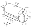
- the drawing It is a figure which shows the state in which the liquid level detection apparatus by 1st embodiment was installed in the washer tank. It is a perspective view which shows typically the primary float and secondary float which were mutually assembled
- FIG. 6B is a diagram showing a state where the liquid level is rising due to replenishment of the washer liquid
- FIG. 6C is a state where the liquid level of the washer liquid is sufficiently higher than the reed switch shaft.
- FIG. It is a figure which shows the state in which the liquid level detection apparatus by 2nd embodiment was installed in the washer tank.
- the washer tank 90 is mounted, for example, in the engine room of the vehicle and stores washer liquid as a liquid.
- the liquid level detection device 100 detects a decrease in the liquid level accompanying a decrease in the washer liquid stored in the washer tank 90.
- the liquid level detection device 100 is inserted into the tank 90 through an opening 91 formed in the washer tank 90.
- the axial direction AD is defined along the direction in which the liquid level detection device 100 is inserted into the opening 91.
- a vertical direction VD is defined along the gravity direction.
- a direction substantially orthogonal to the axial direction AD and the vertical direction VD is defined as a width direction WD.
- the liquid level detection device 100 includes a housing 20, a float unit 30, a magnet 50, and a reed switch 40.
- the housing 20 is fixed to the washer tank 90.
- the housing 20 includes a lid part 21, a reed switch shaft 23, and a restriction part 26.
- the lid portion 21 is formed larger than the opening 91.
- the lid 21 liquid-tightly closes the opening 91 from the outside of the washer tank 90.
- the reed switch shaft 23 extends in a cylindrical shape from the lid portion 21 along the axial direction AD.
- the reed switch shaft 23 forms a housing chamber 24 that houses the reed switch 40.
- a flange 25 is formed at the tip of the reed switch shaft 23 in the extending direction.
- the flange portion 25 is formed in a plate shape whose longitudinal direction is the width direction WD.
- the restricting portion 26 is a wall portion extending in the vertical direction VD. The restricting portion 26 restricts the rotation of the float portion 30 around the reed switch shaft 23 by contacting the float portion 30.
- the float part 30 is formed of a material having a specific gravity smaller than that of the washer liquid so that it can float on the liquid surface of the washer liquid.
- the float part 30 is formed of a polypropylene resin or the like to which a foaming agent is added.
- the float part 30 is formed in a columnar shape extending in the axial direction AD.
- the float portion 30 is provided with a through hole 31 and a convex wall portion 32.
- the through hole 31 penetrates the float part 30 in the axial direction AD.
- the inner width of the through hole 31 in the vertical direction VD is set to be larger than the outer width of the flange portion 25 in the width direction WD.
- the inner width in the width direction WD of the through hole 31 is made smaller than the outer width of the flange portion 25 in the width direction WD.
- the magnet 50 is a permanent magnet such as a ferrite magnet.
- the magnet 50 has a rectangular cross section and is formed in a prismatic shape extending in the axial direction AD.
- the magnet 50 is held by the float unit 30 and is located above the reed switch shaft 23. The magnet 50 can move up and down following the liquid level together with the float 30.
- the reed switch 40 is a detection element for detecting the height of the liquid level.
- the reed switch 40 has a main body portion 43 formed in a cylindrical shape and a pair of leads 41 and 42 extending from both ends of the main body portion 43.
- the reed switch 40 is accommodated in the accommodating chamber 24 in a posture in which the axial direction of the main body portion 43 is aligned with the axial direction AD.
- the main body portion 43 is a hollow glass tube and accommodates the end portions of the leads 41 and 42 (hereinafter referred to as “lead end portions”). Each lead end portion is provided so as to be able to bend, and faces each other with a predetermined interval.
- the lead ends When a magnetic field is applied to the leads 41 and 42 from the outside, the lead ends are attracted to each other by being magnetized to different magnetic poles. When the lead ends contact in this manner, the reed switch 40 is turned on so that it can be conducted between the leads 41 and 42.
- the float 30 is displaced upward with respect to the reed switch shaft 23 when the level of the washer liquid is sufficiently high. In this case, since the magnet 50 is separated from the reed switch 40, the reed switch 40 is turned off. On the other hand, when the washer liquid stored in the washer tank 90 is decreased, the float unit 30 is displaced downward (in the direction of gravity) with respect to the reed switch shaft 23. When the magnet 50 approaches the reed switch 40 in this manner, the reed switch 40 is switched from the off state to the on state by the magnetic field generated by the magnet 50.
- the liquid level detection device 100 there are a large number of magnets incorporated in the prime mover and the generator.
- the magnetic force generated by these magnets acts on the liquid level detection device 100 as external magnetic noise. If the direction of the magnetic field by the magnet 50 matches the direction of the magnetic noise, the magnetic field by the magnet 50 is strengthened by the magnetic noise. As a result, even when the magnet 50 is far from the reed switch 40, the reed switch 40 may remain on.
- the configuration of the float unit 30 for avoiding such a situation will be described below.
- the float unit 30 includes a primary float 60 and a secondary float 70 that are formed so as to float in the washer liquid.
- the primary float 60 is assembled to the reed switch shaft 23 and can be displaced in the vertical direction VD.
- the primary float 60 includes a pair of end plate portions 61 and 63, a connecting portion 66, and a plurality of locking claws 68 in addition to the convex wall portion 32 described above.
- the pair of end plate portions 61 and 63 are formed in a disc shape.
- the end plate portions 61 and 63 are arranged in a posture in which the plate surface direction is aligned with the vertical direction VD and the width direction WD.
- the end plate portions 61 and 63 are opposed to both end surfaces 71 and 73 in the axial direction AD of the secondary float 70, respectively.
- Insertion holes 62 and 64 through which the reed switch shaft 23 is inserted are formed in the end plate portions 61 and 63, respectively.
- One end plate portion 61 facing the end surface 71 close to the flange portion 25 is in contact with the flange portion 25, thereby preventing the float portion 30 from being detached from the reed switch shaft 23.
- the convex wall portion 32 described above is formed on the other end plate portion 63 facing the end surface 73 close to the restriction portion 26 (see FIG. 1).
- the connecting portion 66 extends from the end plate portion 61 to the end plate portion 63 along the axial direction AD.
- the connecting portion 66 is formed in a prismatic shape, and connects the end plate portions 61 and 63 to each other.
- An insertion groove 67 is formed in the connecting portion 66.
- the insertion groove 67 is formed by denting the connecting portion 66 downward.
- the insertion groove 67 extends along the axial direction AD and allows the reed switch shaft 23 to be inserted therethrough.
- the connecting portion 66 contacts the reed switch shaft 23 due to the upward displacement of the primary float 60.
- the connecting portion 66 supports a plurality of locking claws 68.
- the latching claws 68 have a shape extending upward from the connecting portion 66, and a plurality (four in the first embodiment) are provided. Each locking claw 68 is disposed so as to avoid the reed switch shaft 23. A sliding portion 69 is formed at the distal end of each locking claw 68 in the extending direction. The sliding portion 69 projects from the main body portion 68a of the locking claw 68 extending along the vertical direction VD toward the outside in the width direction WD.
- the secondary float 70 shown in FIGS. 2, 4 and 5 is assembled to the primary float 60 and can be displaced in the vertical direction VD with respect to the primary float 60.
- the secondary float 70 has a shape that extends along the axial direction AD, and is formed in a columnar shape in which the side surface portion is partially missing.
- the volume of the secondary float 70 is made larger than the volume of the primary float 60.
- the buoyancy acting on the secondary float 70 from the washer liquid is made larger than the buoyancy acting on the primary float 60 from the washer liquid.
- a holding hole 78, an insertion groove 75, and a plurality of guide grooves 76 are formed in the secondary float 70.
- the holding hole 78 is provided at the center in the axial direction AD of the secondary float 70 and is located above the reed switch 40.
- the holding hole 78 is an opening that penetrates the secondary float 70 in the radial direction.
- the holding hole 78 is formed slightly smaller than the magnet 50.
- a magnet 50 is embedded in the holding hole 78.
- the insertion groove 75 is formed by denting the secondary float 70 upward.
- the insertion groove 75 extends from the end surface 71 to the end surface 73 along the axial direction AD.
- the secondary float 70 is positioned so as to cover the reed switch shaft 23 from above and sandwich the reed switch shaft 23 from both sides in the width direction WD.
- a plurality of guide grooves 76 are provided on the side wall 74 forming the insertion groove 75 in an arrangement corresponding to the locking claws 68.
- Each guide groove 76 extends along the vertical direction VD.
- Each sliding portion 69 is accommodated in each guide groove 76.
- the sliding portion 69 slides in the guide groove 76 accommodated by the relative displacement of the secondary float 70 with respect to the primary float 60.
- the locking claw 68 locks the secondary float 70 by bringing the sliding portion 69 into contact with the peripheral wall portion 77 of the guide groove 76.
- the upward displacement of the secondary float 70 is restricted.
- the guide groove 76 and the sliding portion 69 cooperate to define a range in which the secondary float 70 is relatively displaced with respect to the primary float 60.
- the secondary float 70 described above is accommodated in a space sandwiched between a pair of end plate portions 61 and 63 arranged in the axial direction AD shown in FIG.
- the primary float 60 and the secondary float 70 form a float portion 30 having a cylindrical shape.
- the cross sections of the primary float 60 and the secondary float 70 combined with each other have a circular shape having a smaller diameter than the opening 91 (see FIG. 1). Therefore, the primary float 60 and the secondary float 70 can pass through the opening 91 together.
- the insertion holes 62 and 64 and the insertion groove 67 of the primary float 60 and the insertion groove 75 of the secondary float 70 form the through hole 31 in the float portion 30.
- the secondary float 70 When the liquid level is located below the reed switch shaft 23 as the washer liquid decreases, the secondary float 70 is accommodated in the primary float 60 as shown in FIG. 6A.
- the primary float 60 and the secondary float 70 are suspended from the reed switch shaft 23 by the action of gravity. In this state, since the reed switch 40 is in a state of being close to the magnet 50, it is turned on.
- the secondary float 70 When the liquid level of the washer liquid is sufficiently high with respect to the reed switch shaft 23, as shown in FIG. 6C, the secondary float 70 is further displaced relative to the primary float 60 that has risen to the maximum. As a result, the secondary float 70 continues to rise up to a position where each sliding portion 69 comes into contact with each peripheral wall portion 77 of each guide groove 76 while the reed switch shaft 23 is detached from the insertion groove 75. In this way, the amount of displacement by which the secondary float 70 can move upward with respect to the primary float 60 is defined as a second stroke amount St2.
- the secondary float 70 can be further displaced relative to the primary float 60 in the vertical direction, so the magnet 50 adds the first stroke amount St1 and the second stroke amount St2.
- the reed switch 40 can be separated by more than the combined distance. Therefore, the distance between the magnet 50 and the reed switch 40 can be secured.
- the reed switch 40 changes from the on state to the off state due to the separation of the magnet 50 as the liquid level rises. It can be switched. Therefore, it is possible to provide the liquid level detection device 100 with improved resistance to external magnetic noise.
- the volume of the secondary float 70 is larger than the volume of the primary float 60. Therefore, the buoyancy acting on the secondary float 70 is larger than the buoyancy acting on the primary float 60. Therefore, the primary float 60 can be displaced upward with respect to the reed switch shaft 23 while being assisted by the buoyancy of the secondary float 70 (see FIG. 6B). Furthermore, when the primary float 60 is displaced upward as much as possible with respect to the reed switch shaft 23, the secondary float 70 with buoyancy secured can be reliably displaced upward with respect to the primary float 60 (FIG. 6C). reference).
- the buoyancy of the secondary float 70 is ensured, so that the vertical displacement is made following the liquid level.
- the reliability of the operation of each float 60, 70 can be enhanced. According to the above, since the distance between the magnet 50 and the reed switch 40 is surely ensured, the certainty of the effect of improving the resistance against external magnetic noise is further enhanced.
- the secondary float 70 is accommodated in the primary float 60 as in the first embodiment, the primary float 60 and the secondary float 70 are integrally inserted into the opening 91 of the washer tank 90. obtain. Therefore, the process of inserting the floats 60 and 70 from the opening 91 into the washer tank 90 becomes easy. Therefore, even with the liquid level detection device 100 with improved resistance to external magnetic noise, the workability of the work related to installation in the washer tank 90 can be maintained high.
- FIG. The unit 30 is realized. If it is the above structure, since it becomes easy to ensure the volume of the secondary float 70 with respect to the primary float 60, the buoyancy which acts on the secondary float 70 can also be ensured. As described above, in order to obtain the reliability of the operation of the floats 60 and 70 while ensuring the workability of the work installed in the washer tank 90, the columnar primary float 60 accommodates the columnar secondary float 70. The above-described configuration can be applied.
- the reed switch shaft 23 is inserted into the insertion groove 75 formed by recessing the secondary float 70 upward, the magnet 50 held by the secondary float 70 is The reed switch 40 can be reliably approached (see FIG. 6A). Further, when the magnet 50 is separated from the reed switch 40 due to the relative displacement of the secondary float 70, the reed switch shaft 23 can be detached from the insertion groove 75 (see FIGS. 6C and 5). Therefore, the distance between the magnet 50 and the reed switch 40 can be reliably ensured.
- the configuration in which the insertion groove 75 that is recessed upward is formed in the secondary float 70 can further increase the certainty of the switching operation of the reed switch 40. Accordingly, the resistance of the liquid level detection device 100 to magnetic noise can be further improved.
- the range in which the secondary float 70 is displaced relative to the primary float 60 can be reliably defined.
- the peripheral wall portion 77 and the like for forming the guide groove 76 requires a larger volume than the locking claw 68 and the like for forming the sliding portion 69. Therefore, of the guide groove 76 and the sliding portion 69, the guide groove 76 is provided in the secondary float 70, and the sliding portion 69 is provided in the primary float 60, whereby the volume of the secondary float 70 is reduced to that of the primary float 60. It becomes easy to make it larger than the volume.
- the housing 20 corresponds to the “fixed body” described in the claims
- the reed switch shaft 23 forms the “cylinder portion” described in the claims
- the reed switch 40 It corresponds to the “switch mechanism” described in the range.
- the magnet 50 corresponds to a “magnet body” described in the claims
- the washer tank 90 corresponds to a “container” described in the claims.
- the second embodiment shown in FIG. 7 is a modification of the first embodiment.
- the reed switch 40 is switched from the on state to the off state as the liquid level drops.
- the magnet 50 is installed below the reed switch shaft 23.
- the secondary float 270 When the level of the washer liquid is sufficiently higher than the reed switch shaft 23, the secondary float 270 is accommodated in the primary float 260.
- the primary float 260 and the secondary float 270 have the bottom portion of the insertion groove 75 in contact with the reed switch shaft 23 from below by buoyancy acting on the floats 260 and 270. In this state, since the reed switch 40 is in a state of being close to the magnet 50, it is turned on.
- the secondary float 270 is further displaced downward relative to the primary float 260 that is lowered to the maximum. As a result, the secondary float 270 continues to descend until each slide portion 69 comes into contact with each peripheral wall portion 77 of each guide groove 76 while the reed switch shaft 23 is detached from the insertion groove 75.
- the secondary float 270 can be further displaced relative to the primary float 260, the distance between the magnet 50 and the reed switch 40 can be secured. Therefore, the reed switch 40 can be switched from the on state to the off state by the separation of the magnet 50 as the liquid level drops. Accordingly, even in the second embodiment, the resistance to external magnetic noise can be improved.
- the types of liquid level detection devices can be reduced. More specifically, in the conventional liquid level detection device, since the resistance to magnetic noise is insufficient, the direction of the magnetic force generated by the magnet needs to be opposite to the direction of the magnetic noise. With such an arrangement, the magnetic force and magnetic noise of the magnet cancel each other, so that the malfunction of the reed switch due to the magnetic noise is less likely to occur.
- resistance to magnetic noise is ensured by increasing the moving range of the magnet.
- the same type of liquid level detection device that holds the magnet in a specific mounting posture can be employed. For these reasons, there is no need to change the direction of the reed switch, the direction of the magnet, etc. for each vehicle type, and the cost of the liquid level detection device can be reduced by reducing the types.
- the casing is assembled as a “fixed body” in the opening of the washer tank.
- the configuration corresponding to the “fixed body” may be changed as appropriate.
- an assembly in which a bracket or the like is combined with the above-described housing may correspond to a “fixed body”.
- the prismatic magnet is used as the “magnet body”, but the shape, material, and the like of the configuration corresponding to the “magnet body” may be changed as appropriate. Furthermore, the posture in which the “magnet body” is held may be changed as appropriate. Furthermore, a “magnet body” may be configured by a plurality of magnets. Further, the configuration corresponding to the “switch mechanism” is not limited to the above-described reed switch, and may be changed as appropriate. Furthermore, the configuration corresponding to the “tubular portion” that houses the reed switch is not limited to the cylindrical reed switch shaft 23, and may be changed as appropriate.
- the primary float and the secondary float were formed of foamed polypropylene resin.
- the material of each float is not limited to the above materials, and may be appropriately changed to, for example, a foamed phenol resin.
- the primary float material and the secondary float material may be different from each other.
- the part which forms a latching claw and a guide groove for example may be formed with the material different from the main-body part of each float.
- the cylindrical float portion is formed by accommodating the secondary float in the primary float.
- the shape of each float may be changed as appropriate.
- the primary float may be accommodated in the secondary float.
- the volume of the primary float may be the same as or larger than the volume of the secondary float.
- the buoyancy acting on the primary float from the liquid may be greater than the buoyancy acting on the secondary float from the liquid.
- the relative displacement of the primary float relative to the reed switch shaft occurs prior to the relative displacement of the secondary float relative to the primary float.
- the relative displacement of the secondary float relative to the primary float may occur prior to the relative displacement of the primary float relative to the reed switch shaft.
- the relative displacement of the secondary float relative to the primary float and the relative displacement of the primary float relative to the reed switch shaft may occur in parallel.
- the guide groove 76 and the sliding portion 69 are provided in order to restrict the relative displacement of the secondary float in the direction away from the primary float.
- the configuration for restricting such displacement is not limited to the above-described configuration, and may be changed as appropriate.
- the secondary float may be provided with a sliding portion
- the primary float may be provided with a guide groove.
- the arrangement and number of guide grooves and sliding portions provided in each float are not limited to four, and may be changed as appropriate.
- the present disclosure has been described based on the example applied to the liquid level detecting device that detects the height of the level of the washer liquid stored in the vehicle washer tank. It is not limited to detection of surface height.
- the present disclosure can be applied to a liquid level detection device in a container for other liquids mounted on a vehicle, such as engine oil, brake fluid, engine cooling water, and fuel.
- the present disclosure is applicable not only to vehicles but also to liquid level detection devices used in containers for various consumer devices and various transport machines.
Landscapes
- Physics & Mathematics (AREA)
- Fluid Mechanics (AREA)
- General Physics & Mathematics (AREA)
- Engineering & Computer Science (AREA)
- Textile Engineering (AREA)
- Level Indicators Using A Float (AREA)
Abstract
液面検出装置は、液体を貯留する容器(90)に対し固定される固定体(20)と、液体に浮かぶよう形成され、固定体(20)に組み付けられて重力方向に沿った上下に変位可能な一次フロート(60,260)と、液体に浮かぶよう形成され、一次フロート(60,260)に組み付けられて一次フロート(60,260)に対し上下に変位可能な二次フロート(70,270)と、二次フロート(70,270)に保持されることで上下に移動する磁石体(50)と、固定体(20)に保持され、磁界を発生させる磁石体(50)の近接によって、オフ状態からオン状態へと切り替わるスイッチ機構(40)と、を備える。
Description
本開示は、2013年5月9日に出願された日本出願番号2013-99469号に基づくもので、ここにその記載内容を援用する。
本開示は、液体を貯留する容器に用いられる液面検出装置に関する。
従来、例えば特許文献1には、液体に浮かぶよう形成されたフロートと、フロートに保持された磁石と、磁石の近接によってオフ状態からオン状態に切り替わるリードスイッチとを備えた液面検出装置が開示されている。この液面検出装置において、フロートは、容器に対し固定された本体に組み付けられ、重力方向に沿った上下に移動可能とされている。
ここで、液面検出装置は、外部から磁気ノイズの作用を受ける環境下において使用され得る。すると、磁石の発生させる磁界の向きが、外部から作用する磁気ノイズの向きと一致する場合が生じ得る。この場合、磁石の磁界は、磁気ノイズによって強められてしまう。そのため、磁石及びリードスイッチ間の距離の確保が不十分な液面検出装置では、磁石がリードスイッチから最大限離れたとしても、リードスイッチにつきオン状態からオフ状態への切り替わりが不可能となってしまう。
本開示は、上記問題に鑑みてなされたものであって、その目的は、外部から作用する磁気ノイズへの耐性を向上させた液面検出装置を、提供することである。
上記目的を達成するために、本開示の1つの態様は、液体を貯留する容器に対し固定される固定体と、液体に浮かぶよう形成され、固定体に組み付けられて重力方向に沿った上下に変位可能な一次フロートと、液体に浮かぶよう形成され、一次フロートに組み付けられて当該一次フロートに対し上下に変位可能な二次フロートと、二次フロートに保持されることで上下に移動する磁石体と、固定体に保持され、磁界を発生させる磁石体の近接によって、オフ状態からオン状態へと切り替わるスイッチ機構と、を備える液面検出装置とする。
これによれば、磁石体を保持する二次フロートは、上下に変位可能なよう固定体に組み付けられた一次フロートに対し、さらに上下に相対変位可能である。故に、磁石体は、固定体に対して一次フロートが変位可能なストローク量と、一次フロートに対して二次フロートが変位可能なストローク量とを足し合わせた距離以上、固定体に保持されたスイッチ機構から離間し得る。こうして、磁石体及びスイッチ機構間の距離が確保可能とされることにより、磁石体の発生させる磁界の向きが外部の磁気ノイズの向きと一致していた場合でも、スイッチ機構は、磁石体の離間によってオン状態からオフ状態へと切り替わることができる。したがって、外部の磁気ノイズに対する耐性を向上させた液面検出装置の提供が、可能となる。
本開示についての上記目的およびその他の目的、特徴や利点は、添付の図面を参照しながら下記の詳細な記述により、より明確になる。その図面は、
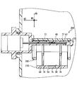
第一実施形態による液面検出装置がウォッシャータンクに設置された状態を示す図である。
第一実施形態の互いに組み付けられた一次フロート及び二次フロートを模式的に示す斜視図である。
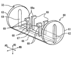
第一実施形態の一次フロートの構成を模式的に示す斜視図である。
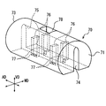
第一実施形態の二次フロートの構成を模式的に示す斜視図である。
第一実施形態の一次フロート及び二次フロートの作動を説明するための図である。
第一実施形態の一次フロート及び二次フロートの作動を説明するための図であり、図6(A)はウォッシャー液の減少に伴い、液面がリードスイッチ軸よりも下方に位置している状態を示す図、図6(B)はウォッシャー液の補充によって液面が上昇している状態を示す図、図6(C)はウォッシャー液の液面がリードスイッチ軸に対し十分に高い状態を示す図である。
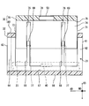
第二実施形態による液面検出装置がウォッシャータンクに設置された状態を示す図である。
以下、複数の実施形態を図面に基づいて説明する。尚、各実施形態において対応する構成要素には同一の符号を付すことにより、重複する説明を省略する場合がある。各実施形態において構成の一部分のみを説明している場合、当該構成の他の部分については、先行して説明した他の実施形態の構成を適用することができる。また、各実施形態の説明において明示している構成の組み合わせばかりではなく、特に組み合わせに支障が生じなければ、明示していなくても複数の実施形態の構成同士を部分的に組み合わせることができる。そして、複数の実施形態及び変形例に記述された構成同士の明示されていない組み合わせも、以下の説明によって開示されているものとする。
(第一実施形態)
図1に示す第一実施形態による液面検出装置100は、ウォッシャータンク90に取り付けられている。ウォッシャータンク90は、例えば車両のエンジンルーム内に搭載され、液体としてのウォッシャー液を貯留している。液面検出装置100は、ウォッシャータンク90に貯留されたウォッシャー液の減少に伴う液面の低下を検出する。液面検出装置100は、ウォッシャータンク90に形成された開口91を通して、当該タンク90内に挿入されている。
(第一実施形態)
図1に示す第一実施形態による液面検出装置100は、ウォッシャータンク90に取り付けられている。ウォッシャータンク90は、例えば車両のエンジンルーム内に搭載され、液体としてのウォッシャー液を貯留している。液面検出装置100は、ウォッシャータンク90に貯留されたウォッシャー液の減少に伴う液面の低下を検出する。液面検出装置100は、ウォッシャータンク90に形成された開口91を通して、当該タンク90内に挿入されている。
まず、液面検出装置100の構成を説明する。尚、以下の説明では、液面検出装置100を開口91に挿入する方向に沿って、軸方向ADが規定されている。さらに、重力方向に沿って、上下方向VDが規定される。そして、軸方向AD及び上下方向VDと実質的に直交する方向が幅方向WDとされている。
液面検出装置100は、筐体20、フロート部30、マグネット50、及びリードスイッチ40を備えている。
筐体20は、ウォッシャータンク90に対し固定されている。筐体20は、蓋部21、リードスイッチ軸23、及び規制部26を有している。蓋部21は、開口91よりも大型に形成されている。蓋部21は、ウォッシャータンク90の外側から、開口91を液密に塞いでいる。リードスイッチ軸23は、軸方向ADに沿って、蓋部21から円筒状に延伸している。リードスイッチ軸23は、リードスイッチ40を収容する収容室24を形成している。リードスイッチ軸23の延伸方向における先端には、鍔部25が形成されている。鍔部25は、幅方向WDを長手とする板状に形成されている。規制部26は、上下方向VDに延伸する壁部である。規制部26は、フロート部30と接触することにより、リードスイッチ軸23まわりのフロート部30の回転を規制する。
フロート部30は、ウォッシャー液の液面に浮かぶことができるよう、ウォッシャー液よりも比重の小さい材料によって形成されている。具体的には、フロート部30は、発泡剤を加えたポリプロピレン樹脂等によって形成されている。フロート部30は、軸方向ADに延伸する円柱状に形成されている。フロート部30には、貫通孔31及び凸壁部32が設けられている。貫通孔31は、フロート部30を軸方向ADに貫通している。貫通孔31の上下方向VDにおける内幅は、鍔部25の幅方向WDにおける外幅よりも大きくされている。一方、貫通孔31の幅方向WDにおける内幅は、鍔部25の幅方向WDの外幅よりも小さくされている。貫通孔31にリードスイッチ軸23が挿通されることにより、フロート部30は、筐体20に組み付けられ、リードスイッチ軸23に対し上下に変位可能となる。凸壁部32は、フロート部30の軸方向ADにおける両端部のうち、蓋部21に近接する一方の端部に形成されている。凸壁部32は、上下方向VDに沿って延設されている。フロート部30がリードスイッチ軸23まわりに回転しようとすると、凸壁部32は、規制部26と接触することによってフロート部30の姿勢を維持させる。
マグネット50は、フェライト磁石等の永久磁石である。マグネット50は、矩形の横断面を有し、軸方向ADに延伸する角柱状に形成されている。マグネット50は、フロート部30に保持されており、リードスイッチ軸23の上方に位置している。マグネット50は、フロート部30とともに液面に追従して上下に移動することができる。
リードスイッチ40は、液面の高さを検出するための検出素子である。リードスイッチ40は、円筒状に形成された本体部分43、及び本体部分43の両端から延出する一対のリード41,42を有している。リードスイッチ40は、本体部分43の軸方向を、軸方向ADに沿わせた姿勢にて、収容室24内に収容されている。本体部分43は、中空のガラス管であって、各リード41,42の各端部(以下、「リード端部」という)を収容している。各リード端部は、撓み可能に設けられており、所定の間隔を開けて対向している。各リード41,42に外部から磁界が作用すると、各リード端部は、異なる磁極に磁化することで、互いに引き合う。こうして各リード端部が接触することにより、リードスイッチ40は、各リード41,42間にて導通可能なオン状態となる。
以上の液面検出装置100では、ウォッシャー液の液面が十分に高いとき、フロート部30は、リードスイッチ軸23に対し上方に変位している。この場合、マグネット50がリードスイッチ40から離間した状態となるため、リードスイッチ40は、オフ状態となる。一方、ウォッシャータンク90に貯留されたウォッシャー液が減少した際には、フロート部30は、リードスイッチ軸23に対し下方(重力方向)に変位する。こうしてマグネット50がリードスイッチ40に近接することにより、リードスイッチ40は、マグネット50の発生する磁界によって、オフ状態からオン状態へと切り替わる。
ここで、液面検出装置100の設置されるエンジンルームには、原動機及び発電機等に組み込まれた多数の磁石が存在している。これらの磁石が発生させる磁力は、外部の磁気ノイズとして液面検出装置100に作用する。仮に、マグネット50による磁界の向きが磁気ノイズの向きと一致したとすると、マグネット50による磁界は、磁気ノイズによって強められてしまう。その結果、マグネット50がリードスイッチ40から最大限離れた場合でも、リードスイッチ40がオン状態のままとなる事態が生じ得る。こうした事態の発生を回避するためのフロート部30の構成について、以下説明する。
図1,2に示すように、フロート部30は、それぞれウォッシャー液に浮かぶよう形成された一次フロート60及び二次フロート70等によって構成されている。一次フロート60は、図2,3,5に示すように、リードスイッチ軸23に組み付けられており、上下方向VDに変位可能である。一次フロート60は、上述した凸壁部32に加えて、一対の端板部61,63、連結部66、及び複数の係止爪68を有している。
一対の端板部61,63は、円盤状に形成されている。各端板部61,63は、上下方向VD及び幅方向WDに板面方向を沿わせた姿勢にて、配置されている。各端板部61,63は、二次フロート70の軸方向ADにおける両端面71,73のそれぞれと対向している。端板部61,63には、リードスイッチ軸23を挿通させる挿通穴62,64がそれぞれ形成されている。鍔部25に近接する端面71と対向する一方の端板部61は、鍔部25に接触することで、リードスイッチ軸23からのフロート部30の離脱を防止している。規制部26(図1参照)に近接する端面73と対向する他方の端板部63には、上述した凸壁部32が形成されている。
連結部66は、軸方向ADに沿って端板部61から端板部63まで延伸している。連結部66は、角柱状に形成されており、端板部61,63を互いに連結している。連結部66には、挿通溝67が形成されている。挿通溝67は、連結部66を下方に凹ませることによって形成されている。挿通溝67は、軸方向ADに沿って延伸しており、リードスイッチ軸23を挿通させることができる。連結部66は、一次フロート60の上方への変位により、リードスイッチ軸23に接触する。連結部66は、複数の係止爪68を支持している。
係止爪68は、連結部66から上方に延伸する形状で、複数(第一実施形態では四つ)設けられている。各係止爪68は、リードスイッチ軸23を避けるように配置されている。各係止爪68の延伸方向における先端には、摺動部69が形成されている。摺動部69は、上下方向VDに沿って延伸する係止爪68の本体部分68aから、幅方向WDの外側に向けて突出している。
図2,4,5に示す二次フロート70は、一次フロート60に組み付けられており、この一次フロート60に対し上下方向VDに変位可能である。二次フロート70は、軸方向ADに沿って延伸する形状であって、側面部が部分的に欠損した円柱状に形成されている。二次フロート70の体積は、一次フロート60の体積よりも大きくされている。これにより、ウォッシャー液から二次フロート70に作用する浮力は、ウォッシャー液から一次フロート60に作用する浮力よりも大きくされている。二次フロート70には、保持孔78、挿通溝75、及び複数のガイド溝76が形成されている。
保持孔78は、二次フロート70の軸方向ADにおける中央に設けられており、リードスイッチ40の上方に位置している。保持孔78は、二次フロート70を径方向に貫通する開口である。保持孔78は、マグネット50よりも僅かに小さく形成されている。保持孔78には、マグネット50が埋め込まれている。
挿通溝75は、二次フロート70を上方に凹ませることによって形成されている。挿通溝75は、軸方向ADに沿って端面71から端面73まで延伸している。挿通溝75がリードスイッチ軸23を挿通させることにより、二次フロート70は、リードスイッチ軸23を上方から覆い、且つ、リードスイッチ軸23を幅方向WDの両側から挟むよう位置することとなる。
ガイド溝76は、挿通溝75を形成する側壁74に、係止爪68に対応した配置にて複数(第一実施形態では四つ)設けられている。各ガイド溝76は、上下方向VDに沿って延伸している。各ガイド溝76には、各摺動部69が収容されている。摺動部69は、一次フロート60に対する二次フロート70の相対変位によって、収容されたガイド溝76内を摺動する。二次フロート70が一次フロート60に対し上方に変位すると、係止爪68は、ガイド溝76の周壁部分77に摺動部69を接触させることにより、二次フロート70を係止する。こうして二次フロート70の上方への変位が規制される。以上のように、ガイド溝76及び摺動部69は、協働して、二次フロート70が一次フロート60に対し相対変位する範囲を規定している。
以上の二次フロート70は、図5に示す軸方向ADに並ぶ一対の端板部61,63に挟まれた空間に収容される。こうして、一次フロート60及び二次フロート70は、円柱状を呈するフロート部30を形成する。互いに組み合わされた一次フロート60及び二次フロート70の横断面は、開口91(図1参照)よりも小径な円形状とされている。故に、一次フロート60及び二次フロート70は、一体となって開口91を通過可能となる。また、一次フロート60の各挿通穴62,64及び挿通溝67と、二次フロート70の挿通溝75とが、フロート部30における貫通穴31を形成する。
次に、一次フロート60及び二次フロート70の作動を、図6に基づいて詳しく説明する。
ウォッシャー液に減少に伴い、液面がリードスイッチ軸23よりも下方に位置している場合、図6Aに示すように、二次フロート70は、一次フロート60に収容されている。そして、一次フロート60及び二次フロート70は、重力の作用によって、リードスイッチ軸23にぶら下がった状態となる。この状態では、リードスイッチ40は、マグネット50と近接した状態となるため、オン状態となる。
以上の状態から、ウォッシャー液の補充によって液面が上昇すると、図6Bに示すように、一次フロート60及び二次フロート70は、各フロート60,70に作用する浮力によって、一体で上昇する。挿通溝67の底部がリードスイッチ軸23に下方から接触する位置まで、一次フロート60及び二次フロート70は上昇する。このように、一次フロート60がリードスイッチ軸23に対し上方に移動可能な変位量を、第一ストローク量St1とする。
ウォッシャー液の液面がリードスイッチ軸23に対し十分に高い場合、図6Cに示すように、二次フロート70は、最大限上昇した一次フロート60に対し、さらに上方へ相対変位する。これにより、リードスイッチ軸23が挿通溝75から離脱しつつ、各摺動部69が各ガイド溝76の各周壁部分77に接触する位置まで、二次フロート70の上昇は、継続される。このように、二次フロート70が一次フロート60に対し上方に移動可能な変位量を、第二ストローク量St2とする。
ここまで説明した第一実施形態によれば、二次フロート70が一次フロート60に対しさらに上下に相対変位可能であるため、マグネット50は、第一ストローク量St1と第二ストローク量St2とを足し合わせた距離以上、リードスイッチ40から離間し得る。故に、マグネット50及びリードスイッチ40間の距離は、確保可能となる。以上により、マグネット50の発生させる磁界の向きが外部の磁気ノイズの向きと一致していた場合でも、リードスイッチ40は、液面の上昇に伴うマグネット50の離間により、オン状態からオフ状態へと切り替わることができる。したがって、外部の磁気ノイズに対する耐性を向上させた液面検出装置100の提供が、可能となる。
加えて第一実施形態によれば、二次フロート70の体積が一次フロート60の体積よりも大きい。よって、二次フロート70に作用する浮力は、一次フロート60に作用する浮力よりも大きくなる。故に、一次フロート60は、二次フロート70の浮力に補助されつつ、リードスイッチ軸23に対し上方に変位することができる(図6B参照)。さらに、リードスイッチ軸23に対し一次フロート60が最大限上方に変位した場合では、浮力を確保された二次フロート70は、一次フロート60に対し、確実に上方に変位することができる(図6C参照)。以上のように、フロート部30が一次フロート60及び二次フロート70に分割された構成では、特に二次フロート70の浮力を確保することにより、液面の高さに追従して上下に変位する各フロート60,70の作動の信頼性を高めることができる。以上によれば、マグネット50及びリードスイッチ40間の距離が確実に確保されるようになるので、外部の磁気ノイズに対する耐性を向上させる効果発揮の確実性は、いっそう高められる。
また第一実施形態のように、一次フロート60に二次フロート70が収容される構成であれば、これら一次フロート60及び二次フロート70は、一体となってウォッシャータンク90の開口91に挿入され得る。故に、各フロート60,70を開口91からウォッシャータンク90の内部に挿入する工程は、容易となる。したがって、外部の磁気ノイズに対する耐性を向上させた液面検出装置100であっても、ウォッシャータンク90への設置に係る作業の作業性は、高く維持可能となる。
さらに第一実施形態では、柱状に形成された二次フロート70を、一対の端板部61,63の間に収容することで、一次フロート60及び二次フロート70を一体的な形態としたフロート部30が実現されている。以上の構成であれば、一次フロート60に対する二次フロート70の体積が確保容易となるため、二次フロート70に作用する浮力も、確保され得る。このように、ウォッシャータンク90に設置する作業の作業性を確保しつつ、各フロート60,70の作動の信頼性を獲得するには、枠状の一次フロート60に柱状の二次フロート70を収容させる上述の構成を適用することができる。
また加えて第一実施形態のように、二次フロート70を上方に凹ませてなる挿通溝75にリードスイッチ軸23を挿通させる構成であれば、二次フロート70に保持されたマグネット50は、リードスイッチ40に確実に近接し得る(図6A参照)。さらに、二次フロート70の相対変位によってマグネット50がリードスイッチ40から離間した場合には、リードスイッチ軸23は、挿通溝75から離脱できる(図6C及び図5参照)。故に、マグネット50とリードスイッチ40との間の距離は、確実に確保可能となる。以上のように、二次フロート70に上方に凹む挿通溝75を形成する構成は、リードスイッチ40の切り替わり動作の確実性をいっそう高めることができる。したがって、液面検出装置100の磁気ノイズに対する耐性は、さらに向上可能となる。
さらに加えて第一実施形態のように、ガイド溝76に摺動部69を摺動させる構成であれば、一次フロート60に対し二次フロート70が相対変位する範囲は、確実に規定可能となる。こうした構成において、ガイド溝76を形成するための周壁部分77等は、摺動部69を形成するための係止爪68等よりも、体積を必要とする。故に、ガイド溝76及び摺動部69のうち、ガイド溝76を二次フロート70に設け、摺動部69を一次フロート60に設けることによれば、二次フロート70の体積を一次フロート60の体積よりも大きくすることが容易となるのである。
第一実施形態において、筐体20が特許請求の範囲に記載の「固定体」に相当し、リードスイッチ軸23が特許請求の範囲に記載の「筒部」し、リードスイッチ40が特許請求の範囲に記載の「スイッチ機構」に相当する。さらに、マグネット50が特許請求の範囲に記載の「磁石体」に相当し、ウォッシャータンク90が特許請求の範囲に記載の「容器」に相当する。
(第二実施形態)
図7に示す第二実施形態は、第一実施形態の変形例である。第二実施形態による液面検出装置200において、リードスイッチ40は、液面の下降に伴って、オン状態からオフ状態へと切り替わる。こうした作動を実現するため、マグネット50は、リードスイッチ軸23よりも下方に設置されている。以下、第二実施形態の一次フロート260及び二次フロート270の作動の詳細を、図7に基づいて説明する。
(第二実施形態)
図7に示す第二実施形態は、第一実施形態の変形例である。第二実施形態による液面検出装置200において、リードスイッチ40は、液面の下降に伴って、オン状態からオフ状態へと切り替わる。こうした作動を実現するため、マグネット50は、リードスイッチ軸23よりも下方に設置されている。以下、第二実施形態の一次フロート260及び二次フロート270の作動の詳細を、図7に基づいて説明する。
ウォッシャー液の液面がリードスイッチ軸23に対し十分に高い場合、二次フロート270は、一次フロート260に収容されている。そして、一次フロート260及び二次フロート270は、各フロート260,270に作用する浮力によって、リードスイッチ軸23に挿通溝75の底部を下方から接触させている。この状態では、リードスイッチ40は、マグネット50と近接した状態となるため、オン状態となる。
以上の状態から、ウォッシャー液の減少によって液面が下降すると、一次フロート260及び二次フロート270は、重力の作用によって、一体で下降する。こうして、挿通溝67の底部がリードスイッチ軸23に上方から接触する位置まで、一次フロート260及び二次フロート270は下降する。
さらに、ウォッシャー液の液面が下降すると、二次フロート270は、最大限下降した一次フロート260に対し、さらに下方へ相対変位する。これにより、リードスイッチ軸23が挿通溝75から離脱しつつ、各摺動部69が各ガイド溝76の各周壁部分77に接触する位置まで、二次フロート270の下降は、継続される。
ここまで説明した第二実施形態でも、二次フロート270が一次フロート260に対しさらに上下に相対変位可能であるため、マグネット50及びリードスイッチ40間の距離は、確保可能となる。故に、リードスイッチ40は、液面の下降に伴うマグネット50の離間により、オン状態からオフ状態へと切り替わることができる。したがって、第二実施形態でも、外部の磁気ノイズに対する耐性は、向上可能となる。
上記実施形態の変形例について述べる。以上、複数の実施形態について説明したが、本開示は、上記実施形態に限定して解釈されるものではなく、本開示の要旨を逸脱しない範囲内において種々の実施形態及び組み合わせに適用することができる。
上記実施形態では、液面検出装置の磁気ノイズへの耐性が確保されるため、液面検出装置の種別削減が可能となる。詳しく説明すると、従来の液面検出装置では、磁気ノイズへの耐性が不十分なため、マグネットの発生させる磁力の向きを、磁気ノイズの向きと逆方向にする必要があった。こうした配置により、マグネットの磁力と磁気ノイズとが互いに打ち消し合うこととなるため、磁気ノイズに起因するリードスイッチの誤作動は、生じ難くなる。しかし、上述の対策では、液面検出装置を取り付ける車種毎に、マグネットの取付方向を変更した新たな種別を設ける必要が生じ得た。これに対し、上記実施形態による液面検出装置では、マグネットの移動範囲を大きくすることにより、磁気ノイズへの耐性が確保されている。そのため、液面検出装置を取り付ける車種に係らず、特定の取付姿勢にてマグネットを保持する同一種別の液面検出装置が、採用可能となる。こうした理由により、車種毎にリードスイッチの方向、マグネットの方向等を変える必要がなくなるため、種別削減による液面検出装置の低コスト化が可能となるのである。
上記実施形態では、筐体が「固定体」として、ウォッシャータンクの開口に組み付けられていた。しかし、「固定体」に相当する構成は、適宜変更されてよい。例えば、上述の筐体にブラケット等を組み合わせた組立体が、「固定体」に相当していてもよい。
上記実施形態では、角柱状のマグネットが「磁石体」として用いられていたが、「磁石体」に相当する構成の形状及び材質等は、適宜変更されてよい。さらに、「磁石体」の保持される姿勢も、適宜変更されてよい。さらに、複数のマグネットによって「磁石体」が構成されていてもよい。また、「スイッチ機構」に相当する構成も、上記のリードスイッチに限定されず、適宜変更されてよい。さらに、リードスイッチを収容する「筒部」に相当する構成も、円筒状のリードスイッチ軸23に限定されず、適宜変更されてよい。
上記実施形態では、一次フロート及び二次フロートは、発泡させたポリプロピレン樹脂によって形成されていた。しかし、各フロートの材料は、上記の材料に限定されず、例えば発泡させたフェノール樹脂等に適宜変更されてよい。また、一次フロートの材料と二次フロートの材料とが互いに異なっていてもよい。さらに、例えば係止爪及びガイド溝を形成する部分が、各フロートの本体部分と異なる材料によって形成されていてもよい。
上記実施形態では、二次フロートが一次フロートに収容されることにより、円柱状のフロート部が形成されていた。しかし、各フロートの形状は、適宜変更されてよい。例えば、一次フロートが二次フロートに収容される構成であってもよい。また、一次フロートの体積が、二次フロートの体積と同一又は大きくされていてもよい。同様に、一次フロートに液体から作用する浮力が、二次フロートに液体から作用する浮力より大きくてもよい。
上記実施形態では、液面高さが変化した際に、一次フロートに対する二次フロートの相対変位よりも先に、リードスイッチ軸に対する一次フロートの相対変位が生じていた。しかし、リードスイッチ軸に対する一次フロートの相対変位よりも先に、一次フロートに対する二次フロートの相対変位が生じてもよい。また、一次フロートに対する二次フロートの相対変位と、リードスイッチ軸に対する一次フロートの相対変位とが、並行して生じてもよい。
上記実施形態では、一次フロートから離間する方向への二次フロートの相対変位を規制するため、ガイド溝76及び摺動部69が設けられていた。こうした変位規制のための構成は、上述のものに限定されず、適宜変更されてよい。例えば、二次フロートに摺動部が設けられ、一次フロートにガイド溝が設けられる構成であってもよい。さらに、各フロートに設けられるガイド溝及び摺動部の配置及び数も、四つに限定されず、適宜変更されてよい。
以上、車両のウォッシャータンクに貯留されたウォッシャー液の液面の高さを検出する液面検出装置に適用した例に基づいて本開示を説明したが、本開示の適用対象は、ウォッシャー液の液面高さの検出に限られない。車両に搭載される他の液体、例えばエンジンオイル、ブレーキフルード、エンジン冷却水、燃料等の容器内の液面検出装置に、本開示は適用可能である。さらに、車両用に限らず、各種民生用機器、各種輸送機械が備える容器に用いられる液面検出装置に、本開示は適用可能である。
本開示は、実施例に準拠して記述されたが、本開示は当該実施例や構造に限定されるものではないと理解される。本開示は、様々な変形例や均等範囲内の変形をも包含する。加えて、様々な組み合わせや形態、さらには、それらに一要素のみ、それ以上、あるいはそれ以下、を含む他の組み合わせや形態をも、本開示の範疇や思想範囲に入るものである。
Claims (7)
- 液体を貯留する容器(90)に対し固定される固定体(20)と、
前記液体に浮かぶよう形成され、前記固定体(20)に組み付けられて重力方向に沿った上下に変位可能な一次フロート(60,260)と、
前記液体に浮かぶよう形成され、前記一次フロート(60,260)に組み付けられて当該一次フロート(60,260)に対し上下に変位可能な二次フロート(70,270)と、
前記二次フロート(70,270)に保持されることで上下に移動する磁石体(50)と、
前記固定体(20)に保持され、磁界を発生させる前記磁石体(50)の近接によって、オフ状態からオン状態へと切り替わるスイッチ機構(40)と、を備えることを特徴とする液面検出装置。 - 前記二次フロート(70,270)に前記液体から作用する浮力は、前記一次フロート(60,260)に前記液体から作用する浮力よりも大きいことを特徴とする請求項1に記載の液面検出装置。
- 前記二次フロート(70,270)の体積は、前記一次フロート(60,260)の体積よりも大きいことを特徴とする請求項1又は2に記載の液面検出装置。
- 前記容器(90)に形成された開口(91)を通して、前記一次フロート(60,260)及び前記二次フロート(70,270)が前記容器(90)の内部に挿入される液面検出装置であって、
前記一次フロート(60,260)及び前記二次フロート(70,270)のうち一方(60,260)は、前記一次フロート(60,260)及び前記二次フロート(70,270)のうち他方(70,270)とともに前記開口91を通過可能なよう、当該他方(70,270)の少なくとも一部を収容することを特徴とする請求項1~3のいずれか一項に記載の液面検出装置。 - 前記二次フロート(70)は、柱状に形成され、
前記一次フロート(60)は、前記二次フロート(70)の軸方向(AD)における両端面(71,73)のそれぞれと対向する一対の端板部(61,63)、及び前記一対の端板部(61,63)を互いに連結する連結部(66)を有することを特徴とする請求項1~4のいずれか一項に記載の液面検出装置。 - 前記固定体(20)は、筒状に延伸して前記スイッチ機構(40)を収容する筒部(23)を有し、
前記二次フロート(70,270)は、前記筒部(23)の軸方向に沿って延伸することで当該筒部(23)を挿通させる挿通溝(75)を形成し、前記筒部(23)の軸方向と交差する方向への相対変位によって当該筒部(23)を前記挿通溝(75)から離脱させることを特徴とする請求項1~5のいずれか一項に記載の液面検出装置。 - 前記二次フロート(70,270)は、前記重力方向に沿って延伸するガイド溝(76)を有し、
前記一次フロート(60,260)は、前記ガイド溝(76)内を摺動し、前記二次フロート(70,270)が相対変位する範囲を規定する摺動部(69)を有することを特徴とする請求項1~6のいずれか一項に記載の液面検出装置。
Applications Claiming Priority (2)
| Application Number | Priority Date | Filing Date | Title |
|---|---|---|---|
| JP2013099469A JP2014219316A (ja) | 2013-05-09 | 2013-05-09 | 液面検出装置 |
| JP2013-099469 | 2013-05-09 |
Publications (1)
| Publication Number | Publication Date |
|---|---|
| WO2014181517A1 true WO2014181517A1 (ja) | 2014-11-13 |
Family
ID=51867008
Family Applications (1)
| Application Number | Title | Priority Date | Filing Date |
|---|---|---|---|
| PCT/JP2014/002285 Ceased WO2014181517A1 (ja) | 2013-05-09 | 2014-04-23 | 液面検出装置 |
Country Status (2)
| Country | Link |
|---|---|
| JP (1) | JP2014219316A (ja) |
| WO (1) | WO2014181517A1 (ja) |
Citations (4)
| Publication number | Priority date | Publication date | Assignee | Title |
|---|---|---|---|---|
| US3437771A (en) * | 1967-05-09 | 1969-04-08 | Roylyn Inc | Liquid level sensing means |
| JP2009525484A (ja) * | 2006-01-30 | 2009-07-09 | フランクリン フューエリング システムズ インコーポレーテッド | 液体のレベルおよび密度を測定する装置 |
| JP2010107370A (ja) * | 2008-10-30 | 2010-05-13 | Asmo Co Ltd | 液面レベル検出器 |
| JP2012173010A (ja) * | 2011-02-17 | 2012-09-10 | Denso Corp | 液面レベル検出器 |
-
2013
- 2013-05-09 JP JP2013099469A patent/JP2014219316A/ja active Pending
-
2014
- 2014-04-23 WO PCT/JP2014/002285 patent/WO2014181517A1/ja not_active Ceased
Patent Citations (4)
| Publication number | Priority date | Publication date | Assignee | Title |
|---|---|---|---|---|
| US3437771A (en) * | 1967-05-09 | 1969-04-08 | Roylyn Inc | Liquid level sensing means |
| JP2009525484A (ja) * | 2006-01-30 | 2009-07-09 | フランクリン フューエリング システムズ インコーポレーテッド | 液体のレベルおよび密度を測定する装置 |
| JP2010107370A (ja) * | 2008-10-30 | 2010-05-13 | Asmo Co Ltd | 液面レベル検出器 |
| JP2012173010A (ja) * | 2011-02-17 | 2012-09-10 | Denso Corp | 液面レベル検出器 |
Also Published As
| Publication number | Publication date |
|---|---|
| JP2014219316A (ja) | 2014-11-20 |
Similar Documents
| Publication | Publication Date | Title |
|---|---|---|
| JP6020360B2 (ja) | 液面検出装置 | |
| JP5983494B2 (ja) | 液面検出装置 | |
| JP5829240B2 (ja) | 端子台を備えたモータ | |
| CN105264343B (zh) | 液面检测装置 | |
| JP2017115793A (ja) | 燃料タンク | |
| WO2014181517A1 (ja) | 液面検出装置 | |
| JP2014137271A (ja) | 液面検出モジュール | |
| JP6142821B2 (ja) | 液面検出装置 | |
| JP2017090205A (ja) | 液面検出装置 | |
| JP6156040B2 (ja) | 液面検出装置 | |
| CN112727973B (zh) | 磁性液体减振器 | |
| WO2015001774A1 (ja) | 液面検出装置 | |
| JP6230148B2 (ja) | リザーバタンクおよび車両用ブレーキ装置 | |
| JP5621517B2 (ja) | 液面検出装置 | |
| JP2013096754A (ja) | 液面検出装置の取付構造 | |
| WO2018139257A1 (ja) | 液面検出装置 | |
| JP6287772B2 (ja) | 液面検出装置 | |
| JP2010107370A (ja) | 液面レベル検出器 | |
| JP7806669B2 (ja) | リードスイッチユニット | |
| JP2006308392A (ja) | 液面検出装置の取り付け構造 | |
| KR20250170477A (ko) | 냉각수 레벨 감지 장치 | |
| JP6233832B2 (ja) | リザーバタンクおよび車両用ブレーキ装置 | |
| JP6540447B2 (ja) | 液面検出装置 | |
| WO2015182109A1 (ja) | 液面検出装置 | |
| JP2006317342A (ja) | 液面検出装置 |
Legal Events
| Date | Code | Title | Description |
|---|---|---|---|
| 121 | Ep: the epo has been informed by wipo that ep was designated in this application |
Ref document number: 14794968 Country of ref document: EP Kind code of ref document: A1 |
|
| NENP | Non-entry into the national phase |
Ref country code: DE |
|
| 122 | Ep: pct application non-entry in european phase |
Ref document number: 14794968 Country of ref document: EP Kind code of ref document: A1 |