WO2014178172A1 - 角速度センサ - Google Patents
角速度センサ Download PDFInfo
- Publication number
- WO2014178172A1 WO2014178172A1 PCT/JP2014/002199 JP2014002199W WO2014178172A1 WO 2014178172 A1 WO2014178172 A1 WO 2014178172A1 JP 2014002199 W JP2014002199 W JP 2014002199W WO 2014178172 A1 WO2014178172 A1 WO 2014178172A1
- Authority
- WO
- WIPO (PCT)
- Prior art keywords
- angular velocity
- velocity sensor
- vibration
- weight
- housing
- Prior art date
- Legal status (The legal status is an assumption and is not a legal conclusion. Google has not performed a legal analysis and makes no representation as to the accuracy of the status listed.)
- Ceased
Links
Images



Classifications
-
- G—PHYSICS
- G01—MEASURING; TESTING
- G01C—MEASURING DISTANCES, LEVELS OR BEARINGS; SURVEYING; NAVIGATION; GYROSCOPIC INSTRUMENTS; PHOTOGRAMMETRY OR VIDEOGRAMMETRY
- G01C19/00—Gyroscopes; Turn-sensitive devices using vibrating masses; Turn-sensitive devices without moving masses; Measuring angular rate using gyroscopic effects
- G01C19/56—Turn-sensitive devices using vibrating masses, e.g. vibratory angular rate sensors based on Coriolis forces
-
- H—ELECTRICITY
- H10—SEMICONDUCTOR DEVICES; ELECTRIC SOLID-STATE DEVICES NOT OTHERWISE PROVIDED FOR
- H10N—ELECTRIC SOLID-STATE DEVICES NOT OTHERWISE PROVIDED FOR
- H10N30/00—Piezoelectric or electrostrictive devices
- H10N30/30—Piezoelectric or electrostrictive devices with mechanical input and electrical output, e.g. functioning as generators or sensors
- H10N30/302—Sensors
Definitions
- the present invention relates to an angular velocity sensor that detects a Coriolis force by vibrating a vibrating weight.
- FIG. 1 is a view showing an example of a conventional angular velocity sensor 500.
- FIG. 1 shows a top view and a side sectional view of an angular velocity sensor 500.
- the conventional angular velocity sensor 500 includes a flat substrate 341, a vibrating weight 342, and a housing 343.
- the angular velocity sensor 500 has a vibrating weight 342 in the center of a square flat substrate 341.
- the housing 343 is formed on the outer periphery of the planar substrate 341 so as to surround the vibration weight 342.
- the x-axis direction which is the vibration direction of the vibrating weight 342 is parallel to the direction of the side of the planar substrate 341 as indicated by the arrows.
- Patent Document 1 JP 2010-185739 A
- the angular velocity sensor 500 vibrates the vibrating weight 342 in the direction of the side of the flat substrate 341, stress concentrates on the flat substrate 341 and the region 360 of the housing 343.
- the stress generated in the region 360 has increased, and the strength of the angular velocity sensor 500 has become a problem.
- a casing having a polygonal outer edge, a planar substrate fixed to the casing, and surrounded by the casing, on the planar substrate with respect to the planar substrate
- a vibration weight formed extending in a vertical direction and a vibration portion that vibrates the vibration weight in a predetermined direction.
- the vibration portion is the shortest distance between the outer edge of the housing and the center of gravity of the vibration weight in plan view.
- An angular velocity sensor that vibrates a vibrating weight in a direction different from a linear direction connecting distances is provided.
- FIG. A sectional view of a side surface of the angular velocity sensor 100 is shown.
- the structural example of MEMS340 is shown.
- the structural example of MEMS340 is shown.
- the structural example of MEMS340 is shown.
- the distribution of the stress generated in the MEMS 340 is shown.
- the distribution of the stress generated in the MEMS 340 is shown.
- a difference in deformation amount of the housing 343 according to the vibration direction of the vibration weight 342 is shown.
- a cross-sectional view of the upper surface of the angular velocity sensor 100 is shown.
- FIG. 2 shows a cross-sectional view of the side surface of the angular velocity sensor 100.
- the angular velocity sensor 100 includes a package substrate 310, a case 320, an ASIC 330, a MEMS 340, and an angular velocity calculation unit 350.
- the angular velocity sensor 100 detects the angular velocity based on the Coriolis force generated according to the vibration of the MEMS 340 and the angular velocity.
- the Coriolis force is an inertial force generated perpendicular to the vibration direction when the MEMS 340 is vibrated in the angular velocity sensor 100 having the angular velocity.
- ASIC 330 and MEMS 340 are sequentially stacked on the upper surface of the package substrate 310.
- An angular velocity calculation unit 350 is formed on the upper surface of the package substrate 310.
- Case 320 is arranged on package substrate 310 so as to completely cover ASIC 330, MEMS 340, and angular velocity calculation unit 350.
- the ASIC 330 outputs a drive signal that vibrates the MEMS 340.
- the MEMS 340 includes a vibrating weight 342, a housing 343, and a vibrating unit 348.
- the vibration unit 348 includes a planar substrate 341, a lower electrode 344, a piezoelectric body 345, a drive electrode 346, and a detection electrode 347.
- the vibration unit 348 causes the vibration weight 342 to vibrate in a predetermined direction.
- the shape of the planar substrate 341 may be a polygon or an ellipse.
- the vibrating weight 342 of the MEMS 340 vibrates according to the drive signal from the ASIC 330. At this time, the Coriolis force corresponding to the angular velocity and the vibration direction of the vibration weight 342 is generated in the vibration weight 342.
- the detection electrode 347 outputs a signal corresponding to the generated Coriolis force.
- the MEMS 340 is manufactured by performing a semiconductor manufacturing process on an SOI substrate having a three-layer structure such as Si—SiO 2 —Si.
- the planar substrate 341 formed of the first Si layer has a fixed outer periphery and vibrates according to a drive signal.
- the vibration weight 342 is formed to extend in a direction perpendicular to the planar substrate 341 by deep etching the second Si layer in the SOI substrate.
- the vibrating weight 342 of this example is formed to extend from the center of the lower surface of the flat substrate 341 toward the upper surface of the ASIC 330.
- the vibrating weight 342 has a shape such as a cylinder or an elliptical cylinder, for example.
- the vibrating weight 342 vibrates integrally with the planar substrate 341 in accordance with the drive signal.
- the housing 343 is formed integrally with the planar substrate 341 on the outer periphery of the planar substrate 341 by deep etching the second Si layer in the SOI substrate.
- the housing 343 is formed simultaneously with the formation of the vibration weight 342 and accommodates the vibration weight 342. Note that the housing 343 may be formed separately from the planar substrate 341 and may be fixed to the planar substrate 341 by bonding or the like.
- the housing 343 supports the outer periphery of the flat substrate 341 when the vibrating weight 342 vibrates.
- the housing 343 is preferably not displaced according to the vibration of the vibration weight 342. Accordingly, the vibrating weight 342 can stably vibrate in a predetermined rotation axis direction.
- the housing 343 supports the outer periphery of the planar substrate 341
- the shape of the outer edge of the housing 343 and the shape of the planar substrate 341 are the same in plan view.
- the plan view refers to a case where the surface of the planar substrate 341 is viewed from directly above.
- the housing 343 supports the outer periphery of the flat substrate 341, but may support the inside of the flat substrate 341.
- the shape of the outer edge of the housing 343 may be a polygon, a rectangle, or a square in plan view.
- the polygons, rectangles, and squares include substantially polygons, rectangles, and squares with rounded corners.
- a lower electrode 344 and a piezoelectric body 345 are laminated on the upper surface of the flat substrate 341.
- the lower electrode 344 and the piezoelectric body 345 are formed so as to cover an area of the planar substrate 341 that is not fixed to the housing 343.
- the drive electrode 346 and the detection electrode 347 are arranged in a pair on the upper surface of the piezoelectric body 345 and at positions symmetrical to the vibration weight 342.
- a voltage is applied to the lower electrode 344 so that the voltage is constant.
- the lower electrode 344 is grounded.
- the drive electrode 346 is applied with a voltage corresponding to the direction in which the vibrating weight 342 is vibrated. Accordingly, the piezoelectric body 345 is bent according to the difference between the voltage of the drive signal input to the drive electrode 346 and the voltage of the lower electrode 344.
- the driving electrode 346 is disposed in the vicinity of the position corresponding to the outer periphery of the vibrating weight 342. Since the outer periphery of the vibration weight 342 has the maximum distance from the inner periphery of the housing 343 that is a fixed end of vibration, a large moment is generated in the piezoelectric body 345 near the outer periphery of the vibration weight 342. Therefore, the drive electrode 346 can vibrate the vibrating weight 342 more efficiently than when provided close to the housing 343.
- the detection electrode 347 is disposed in the vicinity of a position corresponding to the inner periphery of the housing 343. The closer the piezoelectric body 345 is to the housing 343, the greater the stress applied during vibration, so that a large current is generated in the piezoelectric body 345 near the inner periphery of the housing 343. Therefore, a larger signal can be detected when the detection electrode 347 is provided closer to the housing 343 than when the detection electrode 347 is provided closer to the vibration weight 342.
- the signal detected by the detection electrode 347 is a signal based on the Coriolis force generated according to the vibration direction of the vibration weight 342 and the angular velocity of the MEMS 340.
- the detection electrode 347 outputs the detected signal to the angular velocity calculation unit 350.
- the angular velocity calculation unit 350 calculates the angular velocity of the angular velocity sensor 100 by processing the signal detected by the detection electrode 347.
- the angular velocity calculation unit 350 detects the Coriolis force generated in the direction perpendicular to the vibration direction of the MEMS 340 and measures the angular velocity.
- the angular velocity sensor 100 can detect angular velocities of a plurality of rotating shafts by switching the vibration direction of the vibration weight 342.
- the angular velocity sensor 100 causes the vibrating weight 342 to vibrate intermittently and switches a plurality of vibration directions. Thereby, the angular velocity sensor 100 measures the angular velocity of each rotating shaft at an arbitrary time.
- FIG. 3 shows a configuration example of the MEMS 340.
- the MEMS 340 includes a rectangular planar substrate 341, a drive electrode 346, a detection electrode 347, and an electrode pad 349.
- FIG. 3 shows the upper surface of the MEMS 340, and the surface of the planar substrate 341 is the xy plane.
- the x-axis indicates a vibration direction in a plane parallel to the flat substrate 341
- the y-axis indicates a direction perpendicular to the vibration direction in a plane parallel to the flat substrate 341.
- the z axis indicates the signal direction in the direction perpendicular to the planar substrate 341.
- the MEMS 340 has the vibrating weight 342 at an angle greater than 0 degree and smaller than 90 degrees with respect to a straight line connecting the shortest distance between the side of the planar substrate 341 and the vibrating weight 342 on a plane parallel to the planar substrate 341. Vibrate.
- the vibrating weight 342 of this example is vibrated in the x-axis direction that is 45 degrees with respect to a straight line that connects the shortest distance between the side of the flat substrate 341 and the vibrating weight 342.
- the shape of the planar substrate 341 is an elliptical shape
- the side of the planar substrate 341 indicates an elliptical curved portion.
- a case where the x-axis and the y-axis are inclined by 45 degrees with respect to a straight line connecting the shortest distance between the side of the flat substrate 341 and the vibration weight 342 is referred to as a 45-degree arrangement.
- the term “shortest straight line” refers to a straight line connecting the shortest distance between the side of the flat substrate 341 and the vibrating weight 342. Note that the angle of inclination is not limited to 45 degrees.
- the MEMS 340 detects angular velocities in the z-axis direction and the y-axis direction when vibrating the vibrating weight 342 in the x-axis direction.
- the angular velocity in the z-axis direction refers to an angular velocity that rotates about the z-axis.
- the same definition applies to the angular velocities in the x-axis direction and the y-axis direction.
- the electrode pad 349 is connected to the drive electrode 346 and the detection electrode 347.
- the electrode pad 349 inputs a driving signal for vibrating the vibrating weight 342 to the driving electrode 346.
- the MEMS 340 of this example inputs drive signals having opposite phases to the drive electrodes 346 in order to vibrate the vibrating weight 342 in the x-axis direction.
- the drive electrode 346 vibrates the vibration weight 342 in accordance with the input drive signal.
- the drive electrodes 346 are arranged in a pair so as to form an angle larger than 0 degree and smaller than 90 degrees with respect to the shortest straight line on a plane parallel to the flat substrate 341.
- the drive electrodes 346 are arranged along the x-axis and are provided in a pair so as to be symmetric with respect to the vibration weight 342. Therefore, when drive signals having opposite phases are input to the pair of drive electrodes 346, the vibrating weight 342 is vibrated in the x-axis direction.
- the detection electrode 347 detects a signal generated according to the vibration of the vibration weight 342 and outputs it to the electrode pad 349.
- the detection electrode 347 includes a first detection unit 121 and a second detection unit 122.
- the first detection unit 121 and the second detection unit 122 detect the Coriolis force in the triaxial direction generated by the angular velocities around the z axis and the y axis.
- the first detection units 121 are arranged along the y-axis and are provided in a pair so as to be symmetric with respect to the vibration weight 342.
- the first detection unit 121 detects a force generated in a direction perpendicular to the vibration direction. Specifically, the first detector 121 detects Coriolis force in the y-axis direction and Coriolis in the z-axis direction.
- the second detection units 122 are arranged along the x-axis and are provided in a pair so as to be symmetric with respect to the vibration weight 342.
- the second detection unit 122 detects a force generated in the vibration direction.
- the second detection unit 122 detects Coriolis force in the x-axis direction and Coriolis in the z-axis direction.
- the detection electrode 347 outputs a detection signal converted based on the Coriolis force detected by the first detection unit 121 and the second detection unit 122 to the electrode pad 349.
- the electrode pad 349 outputs a detection signal to the angular velocity calculation unit 350.
- the angular velocity calculation unit 350 calculates the angular velocity of the angular velocity sensor 100 based on the outputs of the first detection unit 121 and the second detection unit 122.
- the detection electrode 347 of this example has an elliptical shape with the x axis as the major axis and the y axis as the minor axis.
- the distance between the side of the planar substrate 341 and the vibrating weight 342 in the x-axis direction is larger than the distance between the planar substrate 341 and the vibrating weight 342 in the y-axis direction. Therefore, the resonance frequency of the vibration in the x-axis direction is smaller than the resonance frequency of the vibration in the y-axis direction. Therefore, it is possible to prevent the vibration in the x-axis direction of the vibrating weight 342 from being shifted from the x-axis and leaking in the y-axis direction. It should be noted that the same effect can be obtained even if the planar substrate 341, the vibrating weight 342, and the drive electrode 346 have an elliptical shape.
- the vibration unit 348 causes the vibration weight 342 to vibrate in a direction different from the linear direction connecting the shortest distance between the outer edge of the housing 343 and the center of gravity of the vibration weight 342 in plan view.
- the center of gravity of the vibrating weight 342 indicates the position of the center of gravity of the vibrating weight 342 in a stationary state where the vibrating weight 342 is not vibrated.
- the vibration unit 348 since the shape of the outer edge of the housing 343 is polygonal, the vibration unit 348 is different in a direction different from the perpendicular direction that extends from the center of gravity of the vibration weight 342 to the edge of the outer edge of the housing 343 in plan view. The vibration weight 342 is vibrated.
- the vibration unit 348 may vibrate the vibration weight 342 from the center of gravity of the vibration weight 342 toward the corner of the outer edge of the housing 343 in plan view. With this configuration, the vibration of the vibration weight 342 is hardly transmitted by the housing 343, so that the strength of the housing 343 can be further increased with respect to the vibration of the vibration weight 342.
- the pair of upper electrodes are arranged on a straight line that is different from a straight line that connects the shortest distance between the outer edge of the housing 343 and the center of gravity of the vibration weight 342 in a plan view and that passes through the center of gravity of the vibration weight 342. ing.
- the vibrating weight 342 can be vibrated in the different directions.
- the pair of upper electrodes is the drive electrode 346.
- FIG. 4 shows another configuration example of the MEMS 340.
- the vibration unit 348 may include two pairs of upper electrodes. Each of the two pairs of upper electrodes is arranged so as to sandwich a straight line passing through the center of gravity of the vibrating weight 342 and different from the straight line connecting the shortest distance between the outer edge of the housing 343 and the center of gravity of the vibrating weight 342 in plan view. It's okay.
- the two pairs of upper electrodes are the first detection unit 121 and the second detection unit 122.
- the angular velocity sensor 100 when the shape of the outer edge of the housing 343 is rectangular, the angular velocity sensor 100 has a straight line connecting the shortest distance between the outer edge of the housing 343 and the center of gravity of the vibration weight 342 in plan view.
- the vibrating weight 342 is vibrated so as to form an angle larger than 0 degree and smaller than 90 degrees. For this reason, the stress which generate
- the vibration unit 348 has the outer edge of the housing 343 and the vibration weight 342 in plan view.
- the vibrating weight 342 may be vibrated so as to form 45 degrees with respect to a straight line connecting the shortest distance from the center of gravity. In this case, the distance between the outer edge of the housing 343 and the center of gravity of the vibration weight 342 in the plan view is maximized. As a result, the vibration of the vibration weight 342 is less likely to be transmitted by the housing 343, and the strength of the vibration weight 342 with respect to vibration is further increased.
- the vibration unit 348 is greater than 0 degree with respect to a straight line connecting the shortest distance between the outer edge of the housing 343 and the center of gravity of the vibration weight 342 in plan view.
- the vibrating weight 342 may be vibrated so as to form an angle smaller than 45 degrees.
- FIG. 5 shows a configuration example of the MEMS 340.
- the MEMS 340 differs from FIGS. 3 and 4 in that the vibrating weight 342 is vibrated in the z-axis direction.
- the z axis is a direction perpendicular to the planar substrate 341.
- the electrode pad 349 outputs a driving signal for causing the driving electrode 346 to vibrate the vibrating weight 342.
- the electrode pad 349 of this example inputs drive signals having the same phase to a pair of drive electrodes 346.
- the drive electrodes 346 are arranged along the x-axis and are provided in a pair so as to be symmetric with respect to the vibration weight 342. When the same drive signal is input to the pair of drive electrodes 346, the vibrating weight 342 is vibrated in the z-axis direction perpendicular to the planar substrate 341.
- the detection electrode 347 outputs a detection signal converted based on the Coriolis force detected by the first detection unit 121 and the second detection unit 122 to the electrode pad 349.
- the detection signal is a signal obtained by converting the Coriolis force generated by the angular velocities in the x-axis and y-axis directions.
- the angular velocity sensor 100 vibrates the vibrating weight 342 in the x-axis direction and detects angular velocities in the y-axis and z-axis directions. Further, the angular velocity sensor 100 vibrates the vibrating weight 342 in the z-axis direction and detects angular velocities in the x-axis and y-axis directions.
- the angular velocity sensor 100 can measure the angular velocity in the three-axis direction by switching the vibration of the vibrating weight 342 between the x-axis direction and the z-axis direction. Therefore, the angular velocity sensor 100 does not have to vibrate the vibrating weight 342 in the y-axis direction in order to measure the angular velocity in the triaxial direction.
- FIG. 6 shows a distribution of stress generated in the MEMS 340.
- the upper diagram in FIG. 6 is a top view of the MEMS 340 and shows the stress distribution on the top surface of the housing 343.
- 6 is a cross-sectional view taken along the line AA ′ of the MEMS 340, and shows a stress distribution in a cross section of the housing 343.
- the stress distribution indicates the distribution of deformation when 1 N energy is applied to the vibrating weight 342.
- Each pattern in the figure indicates the amount of deformation of the housing 343.
- the pattern in the figure divides the amount of deformation into equal intervals. That is, the amount of deformation of the housing 343 increases as the pattern changes more.
- the MEMS 340 includes a planar substrate 341 in which the directions of the square sides correspond to the x axis and the y axis, respectively.
- the chip size corresponds to the size of the outer periphery of the planar substrate 341.
- the diaphragm size corresponds to the inner peripheral diameter of the housing 343.
- the weight size corresponds to the size of the outer periphery of the vibrating weight 342. It should be noted that the vibration weight 342 and the housing 343 in this example are equal in height.
- the vibrating weight 342 Since the vibrating weight 342 is vibrated in the x-axis direction, stress concentrates on the region 360 on the x-axis, and the deformation amount becomes maximum. On the other hand, almost no stress is generated in the region 360 on the y-axis. That is, in the housing 343, energy applied to the vibrating weight 342 is not sufficiently dispersed on the xy plane, and stress concentrated in the x-axis direction is generated.
- FIG. 7 is a diagram showing a distribution of stress generated in the MEMS 340.
- FIG. 7 differs from FIG. 6 in that the x-axis and the y-axis are inclined 45 degrees with respect to the side of the planar substrate 341.
- the vibration weight 342 Since there is no region 360 in the vibration direction of the vibration weight 342, the stress generated in the housing 343 is reduced. In addition, since the vibration weight 342 is vibrated with an inclination of 45 degrees with respect to the side of the flat substrate 341, the housing 343 is deformed equally in the region 360 on the x-axis and the y-axis. That is, in the housing 343, the energy applied to the vibrating weight 342 is dispersed on the xy plane, and stress is generated.
- FIG. 8 shows the difference in deformation amount of the housing 343 according to the vibration direction of the vibration weight 342.
- the horizontal axis represents the angle [°] of the vibration direction of the vibration weight 342 with respect to the straight line.
- the vertical axis indicates the amount of deformation generated in the housing 343 in the region 360 on the x-axis and the y-axis.
- the vibration direction of the vibration weight 342 is changed by 15 degrees.
- the rhombus plot is the data for the region 360 on the x-axis
- the square plot is the data for the region 360 on the y-axis.
- the amount of deformation of the housing 343 in the region 360 on the x-axis is the smallest in the case of 0 degree arrangement. And the amount of deformation increases as the angle in the vibration direction increases. On the other hand, the deformation amount of the housing 343 in the region 360 on the y-axis is the largest in the case of the 0 degree arrangement. As the angle in the vibration direction increases, the amount of deformation decreases.
- the planar substrate 341 since the planar substrate 341 has a square shape, the deformation amount with respect to the x-axis and the y-axis is symmetric in the plane. Therefore, in the case of the 45 degree arrangement, the deformation amount in the region 360 on the x axis and the y axis is equal. That is, in the case of the 45 degree arrangement, the stress is evenly distributed on the xy plane, so that the strength of the angular velocity sensor 100 is maximized.
- the vibrating weight 342 may be vibrated so as to form an angle of 15 degrees to 75 degrees with respect to the shortest straight line or 30 degrees to 60 degrees with respect to the shortest straight line.
- the vibration direction of the vibration weight 342 is determined according to the shape of the flat substrate 341 and the position where the vibration weight 342 is installed.
- the vibration direction of the vibration weight 342 may be determined so that the stress generated by the vibration of the vibration weight 342 does not concentrate on the region 360.
- the planar substrate 341 is a square
- the shape of the planar substrate 341 is not limited to a square, and may be a polygon, an ellipse, or other shapes.
- the vibrating weight 342 is vibrated so as to form an angle larger than 0 degree and smaller than 90 degrees with respect to a straight line that is the shortest distance between the side of the flat substrate 341 and the vibrating weight 342. Further, the vibrating weight 342 may be vibrated in the direction of the corner of the flat substrate 341.
- the deformation amount of 45 degree arrangement is smaller than that of 0 degree arrangement. Further, as the chip size is reduced, the difference between the deformation amount of the 45 degree arrangement and the deformation amount of the 0 degree arrangement increases. The deformation amount at 45 degrees is smaller than the deformation amount at 0 degrees.
- the 45 degree arrangement has a high effect of suppressing the deformation amount of the housing 343 when the chip size is small.
- the ratio of the maximum deformation amount of the housing 343 in the case of 0 degree arrangement and the maximum deformation amount of the housing 343 in the case of 45 degree arrangement is a constant ratio of 1.41 in any chip size.
- the 45 degree arrangement has no exception even when the chip size is large, and a certain effect can be obtained regardless of the chip size.
- FIG. 9 shows a cross-sectional view of the upper surface of the angular velocity sensor 100.
- the angular velocity sensor 100 includes a package substrate 310, an ASIC 330, a MEMS 340, a drive electrode 346, a detection electrode 347, and an electrode pad 349.
- a terminal 311 and an angular velocity calculation unit 350 are provided on the package substrate 310. Note that the angular velocity calculation unit 350 may be provided outside the angular velocity sensor 100. Further, the angular velocity calculation unit 350 may be provided inside the ASIC 330.
- the electrode pad 349 is connected to each of the drive electrode 346 and the detection electrode 347.
- the electrode pad 349 outputs a drive signal to the drive electrode 346, and the detection signal is input from the detection electrode 347.
- the electrode pad 349 inputs a detection signal to the terminal 311 through the wiring.
- the terminal 311 outputs the input detection signal to the angular velocity calculation unit 350 via the package substrate 310.
- the terminals 311 are provided according to the number of drive electrodes 346 and detection electrodes 347 to be used.
- the angular velocity calculation unit 350 detects the angular velocity of the angular velocity sensor 100 based on the detection signal. Since the angular velocity calculation unit 350 detects the Coriolis force in the axial direction of the xyz coordinate system corresponding to the vibration direction, it calculates the angular velocity around the axis of the xyz coordinate system.
- the angular velocity calculated by the angular velocity calculator 350 is not limited to the angular velocity around the axis of the xyz coordinate system.
- the angular velocity calculator 350 calculates the angular velocity of a coordinate system different from the xyz coordinate system by converting the axis of the input detection signal data.
- the relationship is expressed by the following equation. That is, in order to obtain the output before the axis conversion, the difference between the outputs from the respective detection electrodes may be multiplied by ⁇ 2.
- the 45 degree arrangement is taken as an example, but the expression (1) can also be applied when the rotation angle is other than 45 degrees.
- the angular velocity calculation unit 350 may calculate an angular velocity around the rotation axis when the direction of the side of the planar substrate 341 is the rotation axis. That is, the angular velocity calculation unit 350 may calculate the angular velocity of the pitch (Pitch). Further, the angular velocity calculation unit 350 may calculate an angular velocity around the rotation axis when the direction of the side of the package substrate 310 is the rotation axis. That is, the angular velocity calculation unit 350 may calculate the angular velocity of the roll. Similarly, the angular velocity calculation unit 350 may calculate the angular velocity of yaw (Yaw).
- the angular velocity sensor 100 includes the angular velocity calculation unit 350 that calculates the angular velocity of the pitch and / or roll, so that a storage space in an electronic device or the like can be reduced.
- DESCRIPTION OF SYMBOLS 100 ... Angular velocity sensor, 121 ... 1st detection part, 122 ... 2nd detection part, 310 ... Package board, 311 ... Terminal, 320 ... Case, 330 ... ASIC, 340 ... MEMS, 341 ... planar substrate, 342 ... vibrating weight, 343 ... housing, 344 ... lower electrode, 345 ... piezoelectric body, 346 ... drive electrode, 347 ... detection electrode, 348 ... vibration unit, 349 ... electrode pad, 350 ... angular velocity calculation unit, 360 ... region, 500 ... angular velocity sensor
Landscapes
- Physics & Mathematics (AREA)
- Engineering & Computer Science (AREA)
- General Physics & Mathematics (AREA)
- Radar, Positioning & Navigation (AREA)
- Remote Sensing (AREA)
- Gyroscopes (AREA)
Abstract
平面視で、外縁の形状が多角形である筐体と、筐体に固定される平面基板と、筐体に囲まれ、平面基板上で平面基板に対し垂直な方向に延びて形成される振動錘と、振動錘を予め定められた方向に振動させる振動部とを備え、振動部は、平面視で、筐体の外縁と振動錘の重心との最短距離を結ぶ直線方向と異なる方向に振動錘を振動させる角速度センサを提供する。
Description
本発明は、振動錘を振動させてコリオリ力を検出する角速度センサに関する。
図1は、従来の角速度センサ500の一例を示す図である。図1は、角速度センサ500の上面図および側面の断面図を示す。従来の角速度センサ500は、平面基板341、振動錘342および筐体343を備える。
角速度センサ500は、正方形の平面基板341の中央に、振動錘342を有する。筐体343は、振動錘342を囲うように、平面基板341の外周に形成される。従来の角速度センサ500は、矢印で示す通り、振動錘342の振動方向であるx軸方向が平面基板341の辺の方向に平行となる。(例えば特許文献1参照)。
[特許文献1] 特開2010-185739号公報
[特許文献1] 特開2010-185739号公報
しかし、角速度センサ500は、振動錘342を平面基板341の辺の方向に振動させるので、平面基板341および筐体343の領域360に応力が集中する。近年、角速度センサ500の小型化に伴い、領域360に発生する応力が増加して、角速度センサ500の強度が問題となっていた。
本発明の第1の態様においては、平面視で、外縁の形状が多角形である筐体と、筐体に固定される平面基板と、筐体に囲まれ、平面基板上で平面基板に対し垂直な方向に延びて形成される振動錘と、振動錘を予め定められた方向に振動させる振動部とを備え、振動部は、平面視で、筐体の外縁と振動錘の重心との最短距離を結ぶ直線方向と異なる方向に振動錘を振動させる角速度センサを提供する。
なお、上記の発明の概要は、本発明の必要な特徴の全てを列挙したものではない。また、これらの特徴群のサブコンビネーションもまた、発明となりうる。
以下、発明の実施の形態を通じて本発明を説明するが、以下の実施形態は請求の範囲にかかる発明を限定するものではない。また、実施形態の中で説明されている特徴の組み合わせの全てが発明の解決手段に必須であるとは限らない。
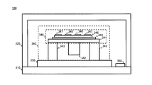
図2は、角速度センサ100の側面の断面図を示す。角速度センサ100は、パッケージ基板310、ケース320、ASIC330、MEMS340および角速度算出部350を備える。
角速度センサ100は、MEMS340の振動と角速度に応じて発生するコリオリ力に基づいて、角速度を検出する。コリオリ力とは、角速度を持つ角速度センサ100において、MEMS340を振動させた場合に振動方向と垂直に発生する慣性力のことである。
パッケージ基板310の上面には、ASIC330およびMEMS340が順に積層される。また、パッケージ基板310の上面には、角速度算出部350が形成される。ケース320は、ASIC330、MEMS340および角速度算出部350を完全に覆うようにパッケージ基板310上に配置される。
ASIC330は、MEMS340を振動させる駆動信号を出力する。MEMS340は、振動錘342、筐体343および振動部348を備える。振動部348は、平面基板341、下部電極344、圧電体345、駆動電極346および検出電極347を備える。振動部348は、振動錘342を予め定められた方向に振動させる。平面基板341の形状は、多角形や楕円形状であってよい。
MEMS340の振動錘342は、ASIC330からの駆動信号に応じて振動する。このとき、振動錘342には、角速度および振動錘342の振動方向に応じたコリオリ力が発生する。検出電極347は、発生したコリオリ力に対応した信号を出力する。
MEMS340は、例えばSi-SiO2-Siといった3層構造を持つSOI基板に半導体製造プロセスを施すことにより製造される。第1のSi層で形成される平面基板341は、外周が固定され、駆動信号に応じて振動する。
振動錘342は、SOI基板における第2のSi層を深堀エッチングすることにより、平面基板341に対し垂直な方向に延びて形成される。本例の振動錘342は、平面基板341の下面中央から、ASIC330の上面に向かって延びて形成される。振動錘342は、例えば円柱、楕円柱等の形状を有する。振動錘342は、駆動信号に応じて、平面基板341と一体となって振動する。
筐体343は、SOI基板における第2のSi層を深堀エッチングすることにより、平面基板341の外周に、平面基板341と一体に形成される。また、筐体343は、振動錘342の形成と同時に形成されて、振動錘342を収容する。なお、筐体343は、平面基板341とは別個に形成され、接着等により平面基板341と固定されてもよい。
筐体343は、振動錘342が振動した場合に、平面基板341の外周を支える。筐体343は、振動錘342の振動に応じて変位しないことが好ましい。これにより、振動錘342は、安定して予め定められた回転軸方向に振動できる。筐体343が平面基板341の外周を支える場合、平面視で、筐体343の外縁の形状と平面基板341の形状とは、同じ形状となる。本明細書において、平面視とは、平面基板341の表面を真上から見た場合を指す。本例では、筐体343が平面基板341の外周を支えているが、平面基板341の内側を支えてもよい。この場合、平面視で、筐体343の外縁の形状が多角形、矩形、または正方形であってよい。ここで、多角形、矩形、及び正方形とは、角が取れて丸くなっている略多角形、略矩形、及び略正方形を含む。
平面基板341の上面には、下部電極344および圧電体345が積層して形成される。下部電極344および圧電体345は、平面基板341のうち、筐体343に固定されていない領域を覆うように形成される。また、駆動電極346および検出電極347は、圧電体345の上面でかつ、振動錘342に対し対称となる位置に、1対にそれぞれ配置される。
下部電極344は、電圧が一定となるように電圧が印加される。例えば、下部電極344は接地される。また、駆動電極346は、振動錘342を振動させる方向に応じた電圧が印加される。これにより、圧電体345は、駆動電極346に入力された駆動信号の電圧と下部電極344の電圧の差に応じて曲げられる。
駆動電極346は、振動錘342の外周に対応する位置の近辺に配置される。振動錘342の外周は、振動の固定端である筐体343の内周からの距離が最大となるので、振動錘342の外周付近の圧電体345には大きなモーメントが発生する。したがって、駆動電極346は、筐体343に近接して設けられる場合よりも、振動錘342を効率的に振動させることができる。
検出電極347は、筐体343の内周に対応する位置の近辺に配置される。圧電体345は、筐体343に近いほど振動時に加えられる応力が大きくなるので、筐体343の内周付近の圧電体345には、大きな電流が発生する。したがって、検出電極347は、振動錘342に近い位置に設けられるよりも、筐体343に近い位置に設けられた方が、より大きな信号を検出できる。
検出電極347が検出する信号は、振動錘342の振動方向およびMEMS340の角速度に応じて発生するコリオリ力に基づく信号である。検出電極347は、検出した信号を角速度算出部350に出力する。
角速度算出部350は、検出電極347が検出した信号を処理することにより角速度センサ100の角速度を算出する。角速度算出部350は、MEMS340の振動方向と垂直な方向に発生するコリオリ力を検出して、角速度を測定する。
角速度センサ100は、振動錘342の振動方向を切り替えることにより、複数の回転軸の角速度を検出できる。角速度センサ100は、振動錘342を間欠に振動させて、複数の振動方向を切り替える。これにより、角速度センサ100は、任意の時間における各回転軸の角速度を測定する。
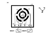
図3は、MEMS340の構成例を示す。MEMS340は、矩形の平面基板341、駆動電極346、検出電極347および電極パッド349を備える。図3は、MEMS340の上面を示し、平面基板341の面をxy平面としている。本明細書において、x軸は、平面基板341と平行な面における振動方向を示し、y軸は、平面基板341と平行な面における振動方向と垂直な方向を示す。また、z軸は、平面基板341と垂直な方向における信号方向を示す。
MEMS340は、平面基板341と平行な面において、平面基板341の辺と振動錘342との最短距離を結ぶ直線に対して、0度より大きく90度より小さい角度をなすように、振動錘342を振動させる。本例の振動錘342は、平面基板341の辺と振動錘342との最短距離を結ぶ直線に対して、45度となるx軸方向に振動される。ここで、平面基板341の形状が楕円形状の場合、平面基板341の辺は、楕円の曲線部分を示す。
本明細書では、x軸およびy軸が、平面基板341の辺と振動錘342との最短距離を結ぶ直線に対して、45度傾斜している場合を、45度配置と呼ぶ。本明細書において、最短直線という語は、平面基板341の辺と振動錘342との最短距離を結ぶ直線のことを指す。なお、傾斜の角度は45度に限定されるものではない。
MEMS340は、x軸方向に振動錘342を振動させる場合、z軸方向およびy軸方向の角速度を検出する。本明細書では、z軸方向の角速度とは、z軸を中心として回転する角速度のことを指す。x軸方向およびy軸方向の角速度に関しても同様に定義する。
電極パッド349は、駆動電極346および検出電極347に接続される。電極パッド349は、駆動電極346に振動錘342を振動させる駆動信号を入力する。本例のMEMS340は、x軸方向に振動錘342を振動させるために、互いに逆位相である駆動信号を駆動電極346にそれぞれ入力する。
駆動電極346は、入力された駆動信号に応じて、振動錘342を振動させる。駆動電極346は、平面基板341と平行な面において、最短直線に対して0度より大きく90度より小さい角度をなすように1対に配置される。
駆動電極346は、x軸上に沿って配列され、振動錘342に対して対称となるように1対に設けられる。そのため、互いに逆位相である駆動信号が1対の駆動電極346に入力された場合、振動錘342は、x軸方向に振動される。
検出電極347は、振動錘342の振動に応じて発生する信号を検出して、電極パッド349に出力する。検出電極347は、第1の検出部121および第2の検出部122を有する。第1の検出部121および第2の検出部122は、z軸周りおよびy軸周りの角速度により発生する3軸方向のコリオリ力を検出する。
第1の検出部121は、y軸上に沿って配列され、振動錘342に対して対称となるように1対に設けられる。第1の検出部121は、振動方向に対し垂直な方向に発生する力を検出する。具体的には、第1の検出部121は、y軸方向のコリオリ力およびz軸方向のコリオリを検出する。
第2の検出部122は、x軸上に沿って配列され、振動錘342に対して対称となるように1対に設けられる。第2の検出部122は、振動方向に発生する力を検出する。第2の検出部122は、x軸方向のコリオリ力およびz軸方向のコリオリを検出する。
検出電極347は、第1の検出部121および第2の検出部122が検出したコリオリ力に基づいて変換した検出信号を電極パッド349に出力する。電極パッド349は、角速度算出部350に検出信号を出力する。角速度算出部350は、第1の検出部121および第2の検出部122の出力に基づき、角速度センサ100の角速度を算出する。
本例の検出電極347は、x軸を長軸として、y軸を短軸とする楕円形状を有する。x軸方向における平面基板341の辺と振動錘342との距離は、y軸方向における平面基板341と振動錘342との距離よりも大きくなる。よって、x軸方向の振動の共振周波数は、y軸方向の振動の共振周波数よりも小さくなる。そのため、振動錘342のx軸方向の振動が、x軸上からずれてy軸方向に漏れるのを防止できる。なお、平面基板341、振動錘342および駆動電極346の形状を楕円形状としても同様の効果が得られる。
角速度センサ100は、振動部348が、平面視で、筐体343の外縁と振動錘342の重心との最短距離を結ぶ直線方向と異なる方向に振動錘342を振動させる。ここで、振動錘342の重心とは、振動錘342が振動されていない静止状態における、振動錘342の重心の位置を指す。角速度センサ100は、筐体343の外縁の形状が多角形であるため、振動部348が、平面視で、振動錘342の重心から筐体343の外縁の辺に下した垂線方向と異なる方向に振動錘342を振動させる。
また、振動部348は、平面視で、振動錘342の重心から筐体343の外縁の角に向かうように振動錘342を振動させてよい。この構成にすることで、振動錘342の振動が筐体343により伝わりにくくなるため、振動錘342の振動に対して、筐体343の強度をさらに高くすることができる。
角速度センサ100は、1対の上部電極が、平面視で、筐体343の外縁と振動錘342の重心との最短距離を結ぶ直線と異なり、且つ振動錘342の重心を通る直線上に配置されている。この構成により、上記異なる方向に振動錘342を振動させることができる。例えば、1対の上部電極は、駆動電極346である。
図4は、MEMS340の他の構成例を示す。図4に示すように、振動部348が上部電極を2対含んでよい。2対の上部電極のそれぞれは、平面視で、筐体343の外縁と振動錘342の重心との最短距離を結ぶ直線と異なり、且つ振動錘342の重心を通る直線を挟み込むように配置されていてよい。例えば、2対の上部電極は、第1の検出部121および第2の検出部122である。
本例のように、筐体343の外縁の形状が矩形である場合、角速度センサ100は、平面視で、筐体343の外縁と振動錘342の重心との最短距離を結ぶ直線に対して、0度より大きく90度より小さい角度をなすように振動錘342を振動させる。このため、振動方向における筐体343に発生する応力が低減される。そのため、本実施形態に係る角速度センサ100は、振動錘342の振動に対する強度が高い。
筐体343の外縁の形状が正方形であり振動錘342の重心と筐体343の外縁の重心とが一致している場合、振動部348は、平面視で、筐体343の外縁と振動錘342の重心との最短距離を結ぶ直線に対して、45度をなすように振動錘342を振動させてよい。この場合、平面視での筐体343の外縁と振動錘342の重心との距離が最大になる。これより、振動錘342の振動が筐体343により伝わりにくくなるため、振動錘342の振動に対する強度がさらに高くなる。なお、筐体343の外縁の形状が正八角形の場合、振動部348は、平面視で、筐体343の外縁と振動錘342の重心との最短距離を結ぶ直線に対して、0度より大きく45度より小さい角度をなすように振動錘342を振動させればよい。
図5は、MEMS340の構成例を示す。MEMS340が、振動錘342をz軸方向に振動させる点で図3、4と異なる。z軸は、平面基板341に対して垂直な方向である。
電極パッド349は、駆動電極346に振動錘342を振動させる駆動信号を出力する。本例の電極パッド349は、同一位相の駆動信号を1対の駆動電極346に入力する。
駆動電極346は、x軸上に沿って配列され、振動錘342に対して対称となるように1対に設けられる。同一の駆動信号が1対の駆動電極346に入力された場合、振動錘342は、平面基板341に垂直なz軸方向に振動される。
検出電極347は、第1の検出部121および第2の検出部122が検出したコリオリ力に基づいて変換した検出信号を電極パッド349に出力する。ここで、検出信号とは、x軸およびy軸方向の角速度により発生するコリオリ力を変換した信号である。
角速度センサ100は、x軸方向に振動錘342を振動させて、y軸およびz軸方向の角速度を検出する。また、角速度センサ100は、z軸方向に振動錘342を振動させて、x軸およびy軸方向の角速度を検出する。
角速度センサ100は、振動錘342の振動をx軸方向およびz軸方向に切り替えて、3軸方向の角速度を測定できる。そのため、角速度センサ100は、3軸方向の角速度を測定するために、振動錘342をy軸方向に振動しなくてもよい。
図6は、MEMS340に発生する応力の分布を示す。図6の上側の図は、MEMS340の上面図であり、筐体343の上面の応力分布を示す。図6の下側の図は、MEMS340のA-A'断面図であり、筐体343の断面の応力分布を示す。応力分布は、振動錘342に1Nのエネルギーが加えられた場合の、変形量の分布を示す。なお、図中のパターンはそれぞれ、筐体343の変形量を示す。図中のパターンは、変形量の大小を等間隔に分割している。つまり、パターンの変化が多い領域ほど、筐体343の変形量が大きい。
MEMS340は、正方形の辺の方向がそれぞれ、x軸およびy軸に対応する平面基板341を有する。チップサイズは、平面基板341の外周のサイズに対応する。ダイアフラムサイズは、筐体343の内周の径に対応する。錘サイズは、振動錘342の外周のサイズに対応する。なお、本例の振動錘342および筐体343の高さは等しい。
振動錘342は、x軸方向に振動されるため、x軸上の領域360に応力が集中し、変形量が最大となる。一方、y軸上の領域360には、ほとんど応力が発生していない。つまり、筐体343には、振動錘342に加えられたエネルギーが、xy平面上に十分に分散されず、x軸方向に集中した応力が発生している。
図7は、MEMS340に発生する応力の分布を示す図である。図7は、x軸およびy軸が、平面基板341の辺に対して45度傾斜している点で図6と異なる。
振動錘342の振動方向に領域360がないので、筐体343に発生する応力が低減される。また、筐体343は、振動錘342が平面基板341の辺に対して45度傾斜して振動されるので、x軸およびy軸上の領域360には均等な変形量が生じる。つまり、筐体343には、振動錘342に加えられたエネルギーが、xy平面上に分散されて、応力が発生している。
図6および図7において、筐体343の側面の断面図を比較すると、図6の方が、筐体343の表面付近の変形量が大きい。また、筐体343の内周付近において、筐体343に発生する応力の集中が顕著である。
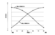
図8は、振動錘342の振動方向に応じた筐体343の変形量の違いを示す。横軸は、直線に対する振動錘342の振動方向の角度[°]を示す。縦軸は、x軸上およびy軸上の領域360における筐体343に発生するそれぞれの変形量を示す。振動錘342の振動方向は、15度ずつ変化される。菱形のプロットは、x軸上の領域360のデータであり、正方形のプロットは、y軸上の領域360のデータを示す。
x軸上の領域360における筐体343の変形量は、0度配置の場合に最も小さくなる。そして、振動方向の角度が大きくなるにつれて、変形量が増加する。一方、y軸上の領域360における筐体343の変形量は、0度配置の場合に最も大きくなる。そして、振動方向の角度が大きくなるにつれて、変形量が減少する。
本実施例では、平面基板341の形状が正方形であるため、x軸およびy軸に対する変形量が、面内で対称となる。そのため、45度配置の場合、x軸上およびy軸上の領域360における変形量が等しくなる。つまり、45度配置の場合、xy平面上で応力が均等に分散されるので、角速度センサ100の強度が最も大きくなる。
振動錘342は、最短直線に対し15度以上75度以下、もしくは、最短直線に対し30度以上60度以下の角度をなすように振動されてよい。振動錘342の振動方向は、平面基板341の形状や振動錘342の設置される位置に応じて決められる。振動錘342の振動方向は、振動錘342の振動により発生する応力が、領域360に集中しないように決定されてよい。
本実施形態では、平面基板341が正方形の例を上げた。しかし、平面基板341の形状は正方形に限られず、多角形や楕円形状、その他の形状でもよい。この場合、振動錘342は、平面基板341の辺と振動錘342との最短距離となる直線に対して、0度より大きく90度より小さい角度をなすように振動される。また、振動錘342は、平面基板341の角の方向に振動されてよい。
45度配置の変形量は、0度配置の変形量よりも小さい。また、チップサイズが小さくなるにつれて、45度配置の変形量と0度配置の変形量の差が大きくなる。45度配置の変形量の方が0度配置の変形量よりも小さくなる。45度配置は、チップサイズが小さい場合に、筐体343の変形量を抑制する効果が高い。
0度配置の場合の筐体343の最大変形量および45度配置の場合の筐体343の最大変形量の比は、いずれのチップサイズの場合にも、1.41という一定の比となる。つまり、45度配置は、チップサイズが大きい場合も例外なく、チップサイズにかかわらず一定の効果が得られる。
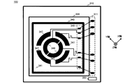
図9は、角速度センサ100の上面の断面図を示す。角速度センサ100は、パッケージ基板310、ASIC330、MEMS340、駆動電極346および検出電極347および電極パッド349を備える。パッケージ基板310上には、端子311および角速度算出部350が設けられる。なお、角速度算出部350は、角速度センサ100の外部に設けられてもよい。また、角速度算出部350は、ASIC330の内部に設けられてもよい。
電極パッド349は、駆動電極346および検出電極347の各電極に接続される。電極パッド349は、駆動電極346に駆動信号を出力し、検出電極347から検出信号が入力される。電極パッド349は、配線を介して、検出信号を端子311に入力する。
端子311は、入力された検出信号を、パッケージ基板310を介して角速度算出部350に出力する。端子311は、使用する駆動電極346および検出電極347の個数に応じて設けられる。
角速度算出部350は、検出信号に基づいて角速度センサ100の角速度を検出する。角速度算出部350は、振動方向に対応するxyz座標系の軸方向のコリオリ力を検出するので、xyz座標系の軸周りの角速度を算出する。
しかし、角速度算出部350の算出する角速度は、xyz座標系の軸周りの角速度に限られない。角速度算出部350は、入力された検出信号のデータを軸変換することにより、xyz座標系と異なる座標系の角速度を算出する。
例えば、xy平面座標の軸変換において、軸変換前の座標をx、y、軸変換後の座標をx´、y´、反時計回りを正とする回転角度をαとすると、軸変換前後の関係は、次式で表記される。

すなわち、軸変換前の出力を得るには、各検出電極からの出力の差分に√2倍すればよい。上記は45度配置を例にしたが、回転角度が45度以外の場合にも式(1)を適用できる。
角速度算出部350は、平面基板341の辺の方向を回転軸としたときの、回転軸周りの角速度を算出してよい。つまり、角速度算出部350は、ピッチ(Pitch)の角速度を算出してよい。また、角速度算出部350は、パッケージ基板310の辺の方向を回転軸としたときの、回転軸周りの角速度を算出してよい。つまり、角速度算出部350は、ロール(Roll)の角速度を算出してよい。同様に、角速度算出部350は、ヨー(Yaw)の角速度を算出してよい。角速度センサ100は、ピッチ及び/またはロールの角速度を算出する角速度算出部350を備えることで、電子機器等への収納スペースが小さくて済む。
以上、本発明を実施の形態を用いて説明したが、本発明の技術的範囲は上記実施の形態に記載の範囲には限定されない。上記実施の形態に、多様な変更または改良を加えることが可能であることが当業者に明らかである。その様な変更または改良を加えた形態も本発明の技術的範囲に含まれ得ることが、請求の範囲の記載から明らかである。
請求の範囲、明細書、および図面中において示した装置、システム、プログラム、および方法における動作、手順、ステップ、および段階等の各処理の実行順序は、特段「より前に」、「先立って」等と明示しておらず、また、前の処理の出力を後の処理で用いるのでない限り、任意の順序で実現しうることに留意すべきである。請求の範囲、明細書、および図面中の動作フローに関して、便宜上「まず、」、「次に、」等を用いて説明したとしても、この順で実施することが必須であることを意味するものではない。
100・・・角速度センサ、121・・・第1の検出部、122・・・第2の検出部、310・・・パッケージ基板、311・・・端子、320・・・ケース、330・・・ASIC、340・・・MEMS、341・・・平面基板、342・・・振動錘、343・・・筐体、344・・・下部電極、345・・・圧電体、346・・・駆動電極、347・・・検出電極、348・・・振動部、349・・・電極パッド、350・・・角速度算出部、360・・・領域、500・・・角速度センサ
Claims (21)
- 平面視で、外縁の形状が多角形である筐体と、
前記筐体に固定される平面基板と、
前記筐体に囲まれ、前記平面基板上で前記平面基板に対し垂直な方向に延びて形成される振動錘と、
前記振動錘を予め定められた方向に振動させる振動部と
を備え、
前記振動部は、平面視で、前記筐体の外縁と前記振動錘の重心との最短距離を結ぶ直線方向と異なる方向に前記振動錘を振動させる角速度センサ。 - 前記振動部は、平面視で、前記振動錘の重心から前記筐体の外縁の辺に下した垂線方向と異なる方向に前記振動錘を振動させる請求項1に記載の角速度センサ。
- 前記振動部は、平面視で、前記振動錘の重心から前記筐体の外縁の角に向かうように前記振動錘を振動させる請求項2に記載の角速度センサ。
- 前記振動部は、
前記平面基板上に設けられた下部電極と、
前記下部電極上に設けられた圧電素子と、
前記圧電素子上に設けられ、前記振動錘に対し対称となる位置に配置される少なくとも1対の上部電極と
を含む請求項1から3のいずれか一項に記載の角速度センサ。 - 前記1対の上部電極は、平面視で、前記筐体の外縁と前記振動錘の重心との最短距離を結ぶ直線と異なり、且つ前記振動錘の重心を通る直線上に配置されている請求項4に記載の角速度センサ。
- 前記振動部は、前記上部電極を2対含み、
前記2対の上部電極のそれぞれは、平面視で、前記筐体の外縁と前記振動錘の重心との最短距離を結ぶ直線と異なり、且つ前記振動錘の重心を通る直線を挟み込むように配置されている請求項4に記載の角速度センサ。 - 前記筐体の外縁の形状は、矩形である請求項1から6のいずれか一項に記載の角速度センサ。
- 前記筐体の外縁の形状は、正方形である請求項7に記載の角速度センサ。
- 平面視で、前記振動錘の重心と前記筐体の外縁の重心とは一致している請求項8に記載の角速度センサ。
- 前記振動部は、前記振動錘の重心から前記筐体の外縁に下した垂線に対して、0度より大きく90度より小さい角度をなすように前記振動錘を振動させる請求項9に記載の角速度センサ。
- 前記振動部は、前記垂線に対し45度の角度をなすように前記振動錘を振動させる請求項10に記載の角速度センサ。
- 前記筐体は、前記平面基板と一体に形成される請求項1から11のいずれか一項に記載の角速度センサ。
- 前記振動錘は、前記平面基板に接して、又は、前記平面基板と一体に形成される請求項1から12のいずれか一項に記載の角速度センサ。
- 前記予め定められた方向に対し垂直な方向に発生する力を検出する第1の検出部と、
を備える請求項1から13のいずれか一項に記載の角速度センサ。 - 前記予め定められた方向に発生する力を検出する第2の検出部と、
を備える請求項14に記載の角速度センサ。 - 前記筐体は、前記平面基板の外周を支え、
前記平面基板は、平面視で、前記筐体の外縁の形状と同じ形状である請求項1から15のいずれか一項に記載の角速度センサ。 - 前記第1の検出部と前記第2の検出部の出力に基づき、前記角速度センサの角速度を算出する角速度算出部を備える請求項15に記載の角速度センサ。
- 前記角速度算出部は、前記平面基板の辺の方向を回転軸の方向としたときの、該回転軸周りの角速度を算出する請求項17に記載の角速度センサ。
- 前記角速度算出部は、ピッチ及び/またはロールの角速度を算出する請求項17に記載の角速度センサ。
- 前記角速度算出部は、前記平面基板と前記振動錘とをパッケージするパッケージ部材の辺の方向を回転軸の方向としたときの、該回転軸周りの角速度を算出する請求項17に記載の角速度センサ。
- 前記第1の検出部と前記第2の検出部の出力を、前記角速度センサの角速度を算出する角速度算出部に出力する請求項15に記載の角速度センサ。
Priority Applications (2)
| Application Number | Priority Date | Filing Date | Title |
|---|---|---|---|
| JP2015514748A JPWO2014178172A1 (ja) | 2013-04-30 | 2014-04-17 | 角速度センサ |
| US14/923,638 US20160047652A1 (en) | 2013-04-30 | 2015-10-27 | Angular velocity sensor |
Applications Claiming Priority (2)
| Application Number | Priority Date | Filing Date | Title |
|---|---|---|---|
| JP2013-095660 | 2013-04-30 | ||
| JP2013095660 | 2013-04-30 |
Related Child Applications (1)
| Application Number | Title | Priority Date | Filing Date |
|---|---|---|---|
| US14/923,638 Continuation US20160047652A1 (en) | 2013-04-30 | 2015-10-27 | Angular velocity sensor |
Publications (1)
| Publication Number | Publication Date |
|---|---|
| WO2014178172A1 true WO2014178172A1 (ja) | 2014-11-06 |
Family
ID=51843317
Family Applications (1)
| Application Number | Title | Priority Date | Filing Date |
|---|---|---|---|
| PCT/JP2014/002199 Ceased WO2014178172A1 (ja) | 2013-04-30 | 2014-04-17 | 角速度センサ |
Country Status (3)
| Country | Link |
|---|---|
| US (1) | US20160047652A1 (ja) |
| JP (1) | JPWO2014178172A1 (ja) |
| WO (1) | WO2014178172A1 (ja) |
Cited By (1)
| Publication number | Priority date | Publication date | Assignee | Title |
|---|---|---|---|---|
| JP2018021825A (ja) * | 2016-08-03 | 2018-02-08 | パナソニックIpマネジメント株式会社 | 通信システム、端末、通信システムの時刻補正方法、及びプログラム |
Citations (4)
| Publication number | Priority date | Publication date | Assignee | Title |
|---|---|---|---|---|
| JPH10132572A (ja) * | 1996-11-01 | 1998-05-22 | Japan Aviation Electron Ind Ltd | 静電駆動型角速度センサ |
| JP2002350138A (ja) * | 2001-05-28 | 2002-12-04 | Wacoh Corp | 加速度と角速度との双方を検出する装置 |
| JP2005031097A (ja) * | 2004-09-27 | 2005-02-03 | Kazuhiro Okada | 加速度と角速度との双方を検出する装置 |
| WO2013032003A1 (ja) * | 2011-09-02 | 2013-03-07 | 北陸電気工業株式会社 | 角速度センサ |
Family Cites Families (5)
| Publication number | Priority date | Publication date | Assignee | Title |
|---|---|---|---|---|
| JPH11281370A (ja) * | 1998-03-30 | 1999-10-15 | Miyota Kk | 二軸角速度センサ |
| US7677076B2 (en) * | 2004-10-07 | 2010-03-16 | Panasonic Corporation | Angular velocity sensor unit and angular velocity sensor diagnosing device |
| JP2007101531A (ja) * | 2005-09-06 | 2007-04-19 | Seiko Instruments Inc | 力学量センサ |
| JP2010145315A (ja) * | 2008-12-22 | 2010-07-01 | Yamaha Corp | 振動ジャイロスコープ |
| JP5988494B2 (ja) * | 2013-02-04 | 2016-09-07 | 富士フイルム株式会社 | 角速度センサ及びその製造方法 |
-
2014
- 2014-04-17 JP JP2015514748A patent/JPWO2014178172A1/ja active Pending
- 2014-04-17 WO PCT/JP2014/002199 patent/WO2014178172A1/ja not_active Ceased
-
2015
- 2015-10-27 US US14/923,638 patent/US20160047652A1/en not_active Abandoned
Patent Citations (4)
| Publication number | Priority date | Publication date | Assignee | Title |
|---|---|---|---|---|
| JPH10132572A (ja) * | 1996-11-01 | 1998-05-22 | Japan Aviation Electron Ind Ltd | 静電駆動型角速度センサ |
| JP2002350138A (ja) * | 2001-05-28 | 2002-12-04 | Wacoh Corp | 加速度と角速度との双方を検出する装置 |
| JP2005031097A (ja) * | 2004-09-27 | 2005-02-03 | Kazuhiro Okada | 加速度と角速度との双方を検出する装置 |
| WO2013032003A1 (ja) * | 2011-09-02 | 2013-03-07 | 北陸電気工業株式会社 | 角速度センサ |
Cited By (1)
| Publication number | Priority date | Publication date | Assignee | Title |
|---|---|---|---|---|
| JP2018021825A (ja) * | 2016-08-03 | 2018-02-08 | パナソニックIpマネジメント株式会社 | 通信システム、端末、通信システムの時刻補正方法、及びプログラム |
Also Published As
| Publication number | Publication date |
|---|---|
| JPWO2014178172A1 (ja) | 2017-02-23 |
| US20160047652A1 (en) | 2016-02-18 |
Similar Documents
| Publication | Publication Date | Title |
|---|---|---|
| CN103542844B (zh) | 带有正交误差补偿的角速率传感器 | |
| JP5524045B2 (ja) | 圧電体膜を用いた振動ジャイロ | |
| US9273962B2 (en) | Physical quantity sensor and electronic device | |
| JP2005283428A (ja) | 力学量センサ装置 | |
| WO2014178172A1 (ja) | 角速度センサ | |
| WO2018003692A1 (ja) | 物理量センサ | |
| JP6058581B2 (ja) | 角速度センサ | |
| JP2012112819A (ja) | 振動ジャイロ | |
| CN101617198B (zh) | 惯性力传感器及复合惯性力传感器 | |
| CN101738184A (zh) | 基于剪应力检测的十字叉结构石英微机械陀螺 | |
| JP2016070739A (ja) | センサ | |
| JP5125138B2 (ja) | 複合センサ | |
| JP6294463B2 (ja) | センサ | |
| JP2011237265A (ja) | 力学量センサ | |
| JP2011043399A (ja) | 多軸角速度センサユニットの製造方法 | |
| JP5729316B2 (ja) | 容量式物理量検出装置 | |
| JP5257115B2 (ja) | 力学量センサ及びその製造方法 | |
| JP2008128879A (ja) | 角速度センサ | |
| JP2006226924A (ja) | 力学量センサ | |
| JP2012233834A (ja) | 物理量センサ | |
| JP2016070738A (ja) | センサ | |
| JP2014165700A (ja) | Mems素子、電子デバイス、電子機器および移動体 | |
| JP2017009441A (ja) | 慣性力センサ | |
| JP2012163386A (ja) | 角速度センサユニットおよびその信号検出方法 | |
| WO2017204057A1 (ja) | ジャイロセンサ及び電子機器 |
Legal Events
| Date | Code | Title | Description |
|---|---|---|---|
| 121 | Ep: the epo has been informed by wipo that ep was designated in this application |
Ref document number: 14791346 Country of ref document: EP Kind code of ref document: A1 |
|
| ENP | Entry into the national phase |
Ref document number: 2015514748 Country of ref document: JP Kind code of ref document: A |
|
| NENP | Non-entry into the national phase |
Ref country code: DE |
|
| 122 | Ep: pct application non-entry in european phase |
Ref document number: 14791346 Country of ref document: EP Kind code of ref document: A1 |