WO2014178161A1 - 伝動ベルト - Google Patents
伝動ベルト Download PDFInfo
- Publication number
- WO2014178161A1 WO2014178161A1 PCT/JP2014/000726 JP2014000726W WO2014178161A1 WO 2014178161 A1 WO2014178161 A1 WO 2014178161A1 JP 2014000726 W JP2014000726 W JP 2014000726W WO 2014178161 A1 WO2014178161 A1 WO 2014178161A1
- Authority
- WO
- WIPO (PCT)
- Prior art keywords
- transmission belt
- rubber layer
- agent
- belt
- rubber
- Prior art date
- Legal status (The legal status is an assumption and is not a legal conclusion. Google has not performed a legal analysis and makes no representation as to the accuracy of the status listed.)
- Ceased
Links
Images

Classifications
-
- F—MECHANICAL ENGINEERING; LIGHTING; HEATING; WEAPONS; BLASTING
- F16—ENGINEERING ELEMENTS AND UNITS; GENERAL MEASURES FOR PRODUCING AND MAINTAINING EFFECTIVE FUNCTIONING OF MACHINES OR INSTALLATIONS; THERMAL INSULATION IN GENERAL
- F16G—BELTS, CABLES, OR ROPES, PREDOMINANTLY USED FOR DRIVING PURPOSES; CHAINS; FITTINGS PREDOMINANTLY USED THEREFOR
- F16G5/00—V-belts, i.e. belts of tapered cross-section
- F16G5/04—V-belts, i.e. belts of tapered cross-section made of rubber
- F16G5/06—V-belts, i.e. belts of tapered cross-section made of rubber with reinforcement bonded by the rubber
- F16G5/08—V-belts, i.e. belts of tapered cross-section made of rubber with reinforcement bonded by the rubber with textile reinforcement
-
- F—MECHANICAL ENGINEERING; LIGHTING; HEATING; WEAPONS; BLASTING
- F16—ENGINEERING ELEMENTS AND UNITS; GENERAL MEASURES FOR PRODUCING AND MAINTAINING EFFECTIVE FUNCTIONING OF MACHINES OR INSTALLATIONS; THERMAL INSULATION IN GENERAL
- F16G—BELTS, CABLES, OR ROPES, PREDOMINANTLY USED FOR DRIVING PURPOSES; CHAINS; FITTINGS PREDOMINANTLY USED THEREFOR
- F16G1/00—Driving-belts
- F16G1/06—Driving-belts made of rubber
- F16G1/08—Driving-belts made of rubber with reinforcement bonded by the rubber
- F16G1/10—Driving-belts made of rubber with reinforcement bonded by the rubber with textile reinforcement
Definitions
- the present invention relates to a transmission belt.
- transmission belts such as V-ribbed belts and V-belts are used as means for transmitting rotational power of engines and motors used in various mechanical devices and automobiles.
- the transmission belt is gradually worn by a load applied when the rotational power is transmitted, and breakage such as a crack occurs.
- a worn or damaged transmission belt cannot transmit power properly and may be cut off during operation of the apparatus. Therefore, it is necessary to replace the power transmission belt in which the wear has progressed by a certain amount or has cracked.
- Patent Document 1 proposes a technique for determining a wear state by providing a colored layer on the bottom surface of a V-belt and monitoring the remaining state of the colored layer. Further, Patent Document 2 proposes a technique for forming a conductive layer on a contact surface of a toothed belt with a pulley and measuring the electrical resistance to determine the wear state of the belt.
- Patent Document 1 is based on a V-belt, and monitors that the colored layer provided on the bottom surface of the V-belt comes into contact with the pulley and is peeled off as a result of wear of the side surface of the V-belt or the side surface of the V-pulley. . Therefore, it cannot be applied immediately to other types of belts.
- an object of the present invention is to realize a transmission belt that is simpler and has a wider range of use and that can detect wear even during use.
- the transmission belt of the present invention is a transmission belt that is wound around a pulley and transmits power, and includes a bottom rubber layer disposed on the pulley contact side, and at least a surface on the pulley contact side.
- the bottom rubber layer contains a luminescent agent.
- deterioration can be detected by monitoring the light emission of the luminescent agent. That is, if the bottom rubber layer is covered with the reinforcing cloth, the light emitting agent of the bottom rubber layer does not emit light, or even if it emits light, it is not detected because it is covered with the reinforcing cloth. On the other hand, when the reinforcing cloth is worn and cracks are generated, for example, the luminescent agent in the bottom rubber layer emits light or light emission is detected. Therefore, by monitoring the presence / absence and intensity of light emission, the state of the transmission belt, such as wear of the reinforcing cloth, can be confirmed.
- any belt such as a V-belt, a flat belt, a V-ribbed belt, or a toothed belt can be used as long as it is a transmission belt using a reinforcing cloth.
- the luminescent agent may emit light upon irradiation with ultraviolet rays.
- luminescent agents there are various types. For example, those that emit light when irradiated with ultraviolet rays can be used. In this case, in order to confirm the state of the transmission belt, it is only necessary to examine the presence or absence of light emission and the intensity by irradiating with ultraviolet rays (for example, the intensity of light emission at the time when the transmission belt needs to be replaced is examined in advance. If the intensity of light emission is confirmed, replace the belt).
- the luminescent agent may emit light upon contact with oxygen.
- the bottom rubber layer emits light even when the transmission belt is not used.
- this light emission is hidden by the reinforcing cloth covering the bottom rubber layer, and the apparent light emission is weakened.
- the light emission in the bottom rubber layer becomes easy to see. Therefore, it is possible to detect wear, cracks, and the like of the reinforcing cloth by monitoring the presence or absence of light emission and intensity.
- the reinforcing cloth may cover the entire transmission belt.
- the transmission belt of the present invention it is possible to detect deterioration while using the transmission belt. Moreover, it is applicable to a wide variety of transmission belts.
- FIG. 1 is a diagram illustrating a power transmission belt according to an embodiment of the present invention.
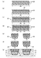
- 2 (a) to 2 (g) are diagrams for explaining a method of manufacturing the transmission belt of FIG.
- FIG. 1 is a view showing an exemplary V-belt B (transmission belt) of the present embodiment.
- the V belt B is used for, for example, an agricultural machine or an industrial machine.
- the dimensions of the V-belt B are not particularly limited.
- the belt circumferential length is 700 to 5000 mm
- the belt width is 16 to 17 mm
- the belt thickness is 8 to 10 mm.
- the V-belt B includes a belt main body 10 formed of a triple layer of a bottom rubber layer 11 on the belt inner peripheral side (pulley contact side), an intermediate adhesive rubber layer 12 and a back rubber layer 13 on the belt outer peripheral side. Prepare. A core wire 14 is embedded in the adhesive rubber layer 12 so as to form a spiral having a pitch in the belt width direction.
- the entire belt body 10 is covered with the reinforcing cloth 15, and the V belt B is a wrapped belt.
- the rubber component of the rubber composition forming the bottom rubber layer 11 is not particularly limited.
- ethylene- ⁇ -olefin elastomer chloroprene rubber (CR), chlorosulfonated polyethylene rubber (CSM), hydrogenated acrylonitrile rubber ( H-NBR) and the like.
- the rubber component may be composed of a single species or a blend of a plurality of species.
- the rubber component forming the bottom rubber layer 11 contains a luminescent agent.
- the luminescent agent is not particularly limited, and may be either organic or inorganic, and a substance that emits fluorescence or phosphorescence, a substance that emits light by contact with oxygen, or the like can be used.
- a coumarin compound that emits light when irradiated with ultraviolet rays is used, and about 5 to 30 parts by mass, more desirably about 10 to 20 parts by mass, is blended with respect to 100 parts by mass of the rubber composition. If the blending amount is too small, sufficient light emission is not achieved. If the blending amount is too large, performance such as durability of the belt is deteriorated. Therefore, an amount in such a range is preferably blended.
- a phosphorescent agent for example, a distyryl luminescent agent, perylene, or the like which is an alumina-based oxide may be used.
- N luminous (Nemoto Special Chemical Co., Ltd., aluminate compound type) which is a phosphorescent agent can also be used. In this case, light is emitted by irradiation with visible light.
- DCJTB (4- (dicyanomethylene) -2-tert-butyl-6 (1,1,7,7-tetramethyljulolidyl-9-enyl) -4H-pyran
- compounding agents include reinforcing materials such as carbon black, vulcanization accelerators, cross-linking agents, anti-aging agents, and softening agents.
- a reinforcing material for example, carbon black, channel black; furnace black such as SAF, ISAF, N-339, HAF, N-351, MAF, FEF, SRF, GPF, ECF, N-234; FT, MT, etc. Thermal black; acetylene black.
- Silica is also mentioned as a reinforcing agent.
- the reinforcing agent may be composed of a single species or a plurality of species.
- the reinforcing material preferably has a blending amount of 30 to 80 parts by mass with respect to 100 parts by mass of the rubber component, from the viewpoint of achieving a good balance between wear resistance and bending resistance.
- the vulcanization accelerator examples include metal oxides such as magnesium oxide and zinc oxide (zinc white), metal carbonates, fatty acids such as stearic acid, and derivatives thereof.
- the vulcanization accelerator may be composed of a single species or a plurality of species.
- the amount of the vulcanization accelerator is 0.5 to 8 parts by mass with respect to 100 parts by mass of the rubber component.
- crosslinking agent examples include sulfur and organic peroxides.
- sulfur may be used, organic peroxide may be used, or both of them may be used in combination.
- the crosslinking agent is preferably used in an amount of 0.5 to 4.0 parts by mass with respect to 100 parts by mass of the rubber component, and in the case of an organic peroxide, the compounding amount with respect to 100 parts by mass of the rubber component is, for example, 0. .5 to 8 parts by mass.
- Antiaging agents include amine-based, quinoline-based, hydroquinone derivatives, phenol-based and phosphite-based agents.
- the anti-aging agent may be composed of a single species or a plurality of species.
- the anti-aging agent is, for example, 0 to 8 parts by mass with respect to 100 parts by mass of the rubber component.
- the softener examples include petroleum-based softeners, mineral oil-based softeners such as paraffin wax, castor oil, cottonseed oil, sesame oil, rapeseed oil, soybean oil, palm oil, palm oil, fallen raw oil, waxy wax, rosin And vegetable oil-based softeners such as pine oil.
- the softener may be composed of a single species or a plurality of species.
- the amount of the softener other than the petroleum-based softener is, for example, 2 to 30 parts by mass with respect to 100 parts by mass of the rubber component.
- layered silicates such as smectite group, vermulite group, kaolin group and the like may be included.
- the bottom rubber layer 11 may contain a friction coefficient reducing material.
- the friction coefficient reducing material include short fibers such as nylon short fibers, vinylon short fibers, aramid short fibers, polyester short fibers, cotton short fibers, and ultrahigh molecular weight polyethylene resins.
- the adhesive rubber layer 12 and the back rubber layer 13 are formed in a band shape having a horizontally long cross section.
- the adhesive rubber layer 12 and the back rubber layer 13 are formed of a rubber composition obtained by heating and pressurizing an uncrosslinked rubber composition in which various compounding agents are blended into a rubber component and then kneading and crosslinking with a crosslinking agent. .
- Examples of the rubber component of the rubber composition forming the adhesive rubber layer 12 and the back rubber layer 13 include ethylene- ⁇ -olefin elastomer, chloroprene rubber (CR), chlorosulfonated polyethylene rubber (CSM), hydrogenated acrylonitrile rubber ( H-NBR) and the like.
- the rubber component of the adhesive rubber layer 12 and the back rubber layer 13 is preferably the same as the rubber component of the bottom rubber layer 11.
- the compounding agent examples include a reinforcing material such as carbon black, a vulcanization accelerator, a crosslinking agent, an anti-aging agent, a softening agent and the like, as in the bottom rubber layer 11.
- the bottom rubber layer 11, the adhesive rubber layer 12, and the back rubber layer 13 may be formed of a different rubber composition, or may be formed of the same rubber composition.
- the core wire 14 is composed of twisted yarns such as polyester fiber (PET), polyethylene naphthalate fiber (PEN), aramid fiber, and vinylon fiber.
- PET polyester fiber
- PEN polyethylene naphthalate fiber
- aramid fiber aramid fiber
- vinylon fiber vinylon fiber
- the reinforcing cloth 15 is constituted by, for example, a woven fabric, a knitted fabric, a non-woven fabric or the like formed of yarns such as cotton, polyamide fiber, polyester fiber, and aramid fiber.
- the reinforcing cloth 15 is coated with rubber paste on the surface on the side of the belt main body 10 and / or an adhesive treatment in which it is immersed in an RFL aqueous solution and heated before molding. An adhesion treatment for drying is performed.
- a rubber sheet 22 such as a chloroprene rubber composition for a compressed rubber layer is wound around a mantle 21 a plurality of times, and a rubber sheet 22 for an adhesive rubber layer is wound thereon. Furthermore, as shown in FIG. 2 (b), a core wire 14 such as a polyester cord to which an adhesive is attached is spirally wound. Further, as shown in FIG. 2C, the rubber sheet 22 for the adhesive rubber layer and the back rubber layer is wound to produce the cylindrical laminated structure 20.
- the cylindrical laminated structure 20 is cut into a predetermined width on the mantle 21 and then removed from the mantle 21.
- the annular laminated structure 20 is wound between a pair of pulleys with the rubber layer on the outer side, and both edges are cut obliquely while rotating to form a V shape. To skiving.
- the lapped annular laminated structure 20 is externally fitted to a cylindrical mold 23, and the entire cylindrical mold 23 is placed in a vulcanizing can and heated and pressurized.
- the rubber component of the annular laminated structure 20 is cross-linked and integrated, whereby the belt forming cloth 25 becomes the reinforcing cloth 15 and the V belt B which is a wrapped V belt is manufactured.
- a luminescent agent about all the rubber sheets 22 may be used, and only the rubber sheet 22 used as the bottom rubber layer 11 may contain the luminescent agent. Further, a rubber sheet 22 containing a luminescent agent is used only in a portion near the bottom surface of the bottom rubber layer 11 (for example, rubber containing a luminescent agent is used only for the several layers on the mantle 22 side in FIG. 2A). Sheet 22).
- the bottom rubber layer 11 may contain a luminescent agent.
- a luminescent agent In order to reduce the cost of the luminescent agent, it is desirable to use rubber that does not contain the luminescent agent in other parts (back rubber layer 13 and the like).
- back rubber layer 13 and the like since it is conceivable that the properties of the rubber are changed (deteriorated) by blending the light-emitting agent, in such a case, it is better to use a rubber containing the light-emitting agent only in a portion that needs to emit light. .
- the belt main body 10 is covered with the reinforcing cloth 15 at the time of manufacture. Accordingly, for example, when the bottom rubber layer 11 is formed of rubber containing a luminescent agent that emits light by ultraviolet rays, even if the ultraviolet rays are irradiated, no light is observed because the bottom rubber layer 11 is not exposed to ultraviolet rays ( However, it is conceivable that slight light emission is observed when the reinforcing cloth 15 is relatively thin, the stitches are rough, or the like).
- the reinforcing cloth 15 is damaged such as abrasion, cracking, and peeling, and the bottom rubber layer 11 is exposed.
- the bottom rubber layer 11 receives the ultraviolet rays, and the blended luminescent agent emits light.
- the breakage of the reinforcing cloth 15 can be found. Such breakage can be detected even when the apparatus using the V-belt B is in operation. That is, in the state where the V-belt B is running, the presence or absence (or intensity) of light emission may be observed by irradiating ultraviolet rays.
- the breakage of the reinforcing cloth 15 can be found by detecting the light emission (or the increase in the intensity).
- a V belt is taken as an example, and a wrapped belt in which the entire belt body made of a rubber composition is wrapped in a reinforcing cloth is taken as an example, but the invention is not limited to this.
- the pulley contact surface has a reinforcing cloth, but the side surface and / or the back surface may be a belt having no reinforcing cloth. In this case, when the reinforcing cloth on the pulley contact surface is broken, light emission is observed on the pulley contacting surface, so that the breakage of the reinforcing cloth can be found.
- the transmission belt of the present disclosure can detect breakage of the reinforcing cloth during operation in various types of belts, and is useful as a means for transmitting rotational power of various mechanical devices.
Landscapes
- Engineering & Computer Science (AREA)
- General Engineering & Computer Science (AREA)
- Textile Engineering (AREA)
- Mechanical Engineering (AREA)
- Chemical & Material Sciences (AREA)
- Materials Engineering (AREA)
- Organic Chemistry (AREA)
Abstract
Description
以下、ラップドVベルトであるVベルトBの製造方法について、図2(a)~(g)を参照して説明する。
11 底部ゴム層
12 接着ゴム層
13 背面ゴム層
14 心線
15 補強布
20 積層構造体
21 マントル
22 ゴムシート
23 円筒金型
25 ベルト形成用布
Claims (10)
- プーリに巻き掛けられて動力を伝達する伝動ベルトであって、
プーリ接触側に配置された底部ゴム層と、少なくともプーリ接触側の表面を補強する補強布とを備え、
前記底部ゴム層は、発光剤を含有することを特徴とする伝動ベルト。 - 請求項1の伝動ベルトにおいて、
前記発光剤は、紫外線の照射により発光することを特徴とする伝動ベルト。 - 請求項1の伝動ベルトにおいて、
前記発光剤は、酸素との接触により発光することを特徴とする伝動ベルト。 - 請求項1の伝動ベルトにおいて、
前記発光剤は、蛍光又は燐光を発する物質であることを特徴とする伝動ベルト。 - 請求項1の伝動ベルトにおいて、
前記発光剤は、クマリン化合物であり、前記底部ゴム層を構成するゴム組成物100重量部に対して5~30質量部含有することを特徴とする伝動ベルト。 - 請求項1の伝動ベルトにおいて、
前記発光剤は、クマリン化合物、アルミナ系酸化物である蓄光剤、ジスチリル系発光剤、ペリレン及びアルミン酸塩化合物系である蓄光剤及びFCJTBの少なくとも一つであることを特徴とする伝動ベルト。 - 請求項1~6のいずれか一つの伝動ベルトにおいて、
前記補強布は、前記伝動ベルト全体を覆っていることを特徴とする伝動ベルト。 - 請求項1~7のいずれか1つの伝動ベルトにおいて、
前記底部ゴム層は、複数のゴムシートをからなる積層構造を有しており、
前記複数のゴムシートは、前記発光剤を含有するゴムシートを含み、
少なくとも最もプーリ接触側のゴムシートは前記発光剤を含有するゴムシートであることを特徴とする伝動ベルト。 - 請求項8の伝動ベルトにおいて、
前記複数のゴムシートは、前記発光剤を含有しないゴムシートを含むことを特徴とする伝動ベルト。 - 請求項1~9のいずれか1つの伝動ベルトにおいて、
前記伝動ベルトは、プーリ接触側とは反対側の背面ゴム層と、前記背面ゴム層と前記底部ゴム層との間に挟まれ且つ少なくとも一つの心線を含む接着ゴム層とを備え、
前記背面ゴム層は前記発光剤を含有することを特徴とする伝動ベルト。
Priority Applications (3)
| Application Number | Priority Date | Filing Date | Title |
|---|---|---|---|
| CN201480022562.4A CN105143712A (zh) | 2013-04-30 | 2014-02-13 | 传动带 |
| JP2015514746A JPWO2014178161A1 (ja) | 2013-04-30 | 2014-02-13 | 伝動ベルト |
| KR1020157032032A KR20160003695A (ko) | 2013-04-30 | 2014-02-13 | 전동벨트 |
Applications Claiming Priority (2)
| Application Number | Priority Date | Filing Date | Title |
|---|---|---|---|
| JP2013095566 | 2013-04-30 | ||
| JP2013-095566 | 2013-04-30 |
Publications (1)
| Publication Number | Publication Date |
|---|---|
| WO2014178161A1 true WO2014178161A1 (ja) | 2014-11-06 |
Family
ID=51843307
Family Applications (1)
| Application Number | Title | Priority Date | Filing Date |
|---|---|---|---|
| PCT/JP2014/000726 Ceased WO2014178161A1 (ja) | 2013-04-30 | 2014-02-13 | 伝動ベルト |
Country Status (5)
| Country | Link |
|---|---|
| JP (1) | JPWO2014178161A1 (ja) |
| KR (1) | KR20160003695A (ja) |
| CN (1) | CN105143712A (ja) |
| TW (1) | TW201441505A (ja) |
| WO (1) | WO2014178161A1 (ja) |
Cited By (4)
| Publication number | Priority date | Publication date | Assignee | Title |
|---|---|---|---|---|
| CN105570383A (zh) * | 2016-02-19 | 2016-05-11 | 山东日久智能输送科技有限公司 | 无污染的农机用v带 |
| WO2016194371A1 (ja) * | 2015-06-04 | 2016-12-08 | バンドー化学株式会社 | 伝動ベルト |
| EP3812612A4 (en) * | 2018-06-25 | 2022-04-13 | Mitsuboshi Belting Ltd. | COVERED CONNECTED V-BELT |
| JP2024000980A (ja) * | 2022-06-21 | 2024-01-09 | バルメット テクノロジーズ オサケユキチュア | ベルト |
Families Citing this family (2)
| Publication number | Priority date | Publication date | Assignee | Title |
|---|---|---|---|---|
| CN107152495A (zh) * | 2017-03-24 | 2017-09-12 | 盖茨优霓塔传动系统(苏州)有限公司 | 包布有齿v带及其制造方法 |
| US11001474B2 (en) * | 2018-01-15 | 2021-05-11 | Otis Elevator Company | Wear detection of elevator belt |
Citations (8)
| Publication number | Priority date | Publication date | Assignee | Title |
|---|---|---|---|---|
| JPS57163041U (ja) * | 1981-04-08 | 1982-10-14 | ||
| JPH03170849A (ja) * | 1989-11-30 | 1991-07-24 | Rikagaku Kenkyusho | 湿度の測定方法 |
| JPH08159976A (ja) * | 1994-11-30 | 1996-06-21 | Nippon Kemitsukusu:Kk | 損傷箇所の警報方法、及び、その検知システム |
| JP2002195349A (ja) * | 2000-12-26 | 2002-07-10 | Mitsuboshi Belting Ltd | 伝動ベルト |
| JP2002371191A (ja) * | 2001-06-13 | 2002-12-26 | Toshiba Corp | マイクロカプセル含有成形品、その検査方法、及びその検査装置 |
| JP2004196916A (ja) * | 2002-12-17 | 2004-07-15 | National Institute Of Advanced Industrial & Technology | 弾性体及びそれを用いた動力伝達装置 |
| JP2009287696A (ja) * | 2008-05-30 | 2009-12-10 | Mitsuboshi Belting Ltd | 動力伝動用ベルト |
| JP2012202538A (ja) * | 2011-03-28 | 2012-10-22 | Toyota Motor Corp | 動力伝達装置 |
Family Cites Families (2)
| Publication number | Priority date | Publication date | Assignee | Title |
|---|---|---|---|---|
| JP4178115B2 (ja) | 2004-01-19 | 2008-11-12 | ゲイツ・ユニッタ・アジア株式会社 | ベルト寿命検知システム |
| JP2009281780A (ja) | 2008-05-20 | 2009-12-03 | Chugoku Electric Power Co Inc:The | 磨耗検査方法 |
-
2014
- 2014-02-13 KR KR1020157032032A patent/KR20160003695A/ko not_active Ceased
- 2014-02-13 WO PCT/JP2014/000726 patent/WO2014178161A1/ja not_active Ceased
- 2014-02-13 JP JP2015514746A patent/JPWO2014178161A1/ja active Pending
- 2014-02-13 CN CN201480022562.4A patent/CN105143712A/zh active Pending
- 2014-02-27 TW TW103106714A patent/TW201441505A/zh unknown
Patent Citations (8)
| Publication number | Priority date | Publication date | Assignee | Title |
|---|---|---|---|---|
| JPS57163041U (ja) * | 1981-04-08 | 1982-10-14 | ||
| JPH03170849A (ja) * | 1989-11-30 | 1991-07-24 | Rikagaku Kenkyusho | 湿度の測定方法 |
| JPH08159976A (ja) * | 1994-11-30 | 1996-06-21 | Nippon Kemitsukusu:Kk | 損傷箇所の警報方法、及び、その検知システム |
| JP2002195349A (ja) * | 2000-12-26 | 2002-07-10 | Mitsuboshi Belting Ltd | 伝動ベルト |
| JP2002371191A (ja) * | 2001-06-13 | 2002-12-26 | Toshiba Corp | マイクロカプセル含有成形品、その検査方法、及びその検査装置 |
| JP2004196916A (ja) * | 2002-12-17 | 2004-07-15 | National Institute Of Advanced Industrial & Technology | 弾性体及びそれを用いた動力伝達装置 |
| JP2009287696A (ja) * | 2008-05-30 | 2009-12-10 | Mitsuboshi Belting Ltd | 動力伝動用ベルト |
| JP2012202538A (ja) * | 2011-03-28 | 2012-10-22 | Toyota Motor Corp | 動力伝達装置 |
Cited By (8)
| Publication number | Priority date | Publication date | Assignee | Title |
|---|---|---|---|---|
| WO2016194371A1 (ja) * | 2015-06-04 | 2016-12-08 | バンドー化学株式会社 | 伝動ベルト |
| JPWO2016194371A1 (ja) * | 2015-06-04 | 2017-06-15 | バンドー化学株式会社 | 伝動ベルト |
| CN105570383A (zh) * | 2016-02-19 | 2016-05-11 | 山东日久智能输送科技有限公司 | 无污染的农机用v带 |
| CN105570383B (zh) * | 2016-02-19 | 2020-05-08 | 山东日久智能输送科技有限公司 | 无污染的农机用v带 |
| EP3812612A4 (en) * | 2018-06-25 | 2022-04-13 | Mitsuboshi Belting Ltd. | COVERED CONNECTED V-BELT |
| US12222020B2 (en) | 2018-06-25 | 2025-02-11 | Mitsuboshi Belting Ltd. | Wrapped joined V-belt |
| JP2024000980A (ja) * | 2022-06-21 | 2024-01-09 | バルメット テクノロジーズ オサケユキチュア | ベルト |
| JP7635490B2 (ja) | 2022-06-21 | 2025-02-26 | バルメット テクノロジーズ オサケユキチュア | ベルト |
Also Published As
| Publication number | Publication date |
|---|---|
| KR20160003695A (ko) | 2016-01-11 |
| CN105143712A (zh) | 2015-12-09 |
| JPWO2014178161A1 (ja) | 2017-02-23 |
| TW201441505A (zh) | 2014-11-01 |
Similar Documents
| Publication | Publication Date | Title |
|---|---|---|
| US9709129B2 (en) | Transmission belt | |
| US9366314B2 (en) | Cover fabric for power transmission belt and toothed belt | |
| CN108700162B (zh) | 齿形带 | |
| CN102803787B (zh) | 齿形带以及齿形带在机油混合物中的应用 | |
| US9702434B2 (en) | Friction transmission belt | |
| KR101516934B1 (ko) | 마찰 전동 벨트 및 그 제조방법 | |
| WO2014178161A1 (ja) | 伝動ベルト | |
| JP6412210B2 (ja) | 摩擦伝動ベルト | |
| US20120058849A1 (en) | Friction drive belt and manufacturing method thereof | |
| CN106233036B (zh) | 传动带以及相关联的传动系统 | |
| KR102062739B1 (ko) | 전동 벨트 및 그 제조방법 | |
| KR102478921B1 (ko) | 마찰 전동 벨트용 심선 및 마찰 전동 벨트 및 그 제조 방법 | |
| JP6438413B2 (ja) | 耐油性伝動ベルト | |
| JP6609395B1 (ja) | 歯付ベルト | |
| CN104428561B (zh) | 传动带及其制造方法以及带传动装置 | |
| KR20170008208A (ko) | 전동벨트 | |
| JP6635753B2 (ja) | ベルト | |
| TW202508836A (zh) | 傳動帶 | |
| RU2588549C2 (ru) | Приводной ремень |
Legal Events
| Date | Code | Title | Description |
|---|---|---|---|
| WWE | Wipo information: entry into national phase |
Ref document number: 201480022562.4 Country of ref document: CN |
|
| 121 | Ep: the epo has been informed by wipo that ep was designated in this application |
Ref document number: 14791948 Country of ref document: EP Kind code of ref document: A1 |
|
| ENP | Entry into the national phase |
Ref document number: 2015514746 Country of ref document: JP Kind code of ref document: A |
|
| NENP | Non-entry into the national phase |
Ref country code: DE |
|
| ENP | Entry into the national phase |
Ref document number: 20157032032 Country of ref document: KR Kind code of ref document: A |
|
| 122 | Ep: pct application non-entry in european phase |
Ref document number: 14791948 Country of ref document: EP Kind code of ref document: A1 |