WO2014175406A1 - ダンパ制御装置 - Google Patents
ダンパ制御装置 Download PDFInfo
- Publication number
- WO2014175406A1 WO2014175406A1 PCT/JP2014/061636 JP2014061636W WO2014175406A1 WO 2014175406 A1 WO2014175406 A1 WO 2014175406A1 JP 2014061636 W JP2014061636 W JP 2014061636W WO 2014175406 A1 WO2014175406 A1 WO 2014175406A1
- Authority
- WO
- WIPO (PCT)
- Prior art keywords
- damper
- speed
- control
- value
- damper speed
- Prior art date
- Legal status (The legal status is an assumption and is not a legal conclusion. Google has not performed a legal analysis and makes no representation as to the accuracy of the status listed.)
- Ceased
Links
Images






Classifications
-
- B—PERFORMING OPERATIONS; TRANSPORTING
- B60—VEHICLES IN GENERAL
- B60G—VEHICLE SUSPENSION ARRANGEMENTS
- B60G17/00—Resilient suspensions having means for adjusting the spring or vibration-damper characteristics, for regulating the distance between a supporting surface and a sprung part of vehicle or for locking suspension during use to meet varying vehicular or surface conditions, e.g. due to speed or load
- B60G17/015—Resilient suspensions having means for adjusting the spring or vibration-damper characteristics, for regulating the distance between a supporting surface and a sprung part of vehicle or for locking suspension during use to meet varying vehicular or surface conditions, e.g. due to speed or load the regulating means comprising electric or electronic elements
- B60G17/018—Resilient suspensions having means for adjusting the spring or vibration-damper characteristics, for regulating the distance between a supporting surface and a sprung part of vehicle or for locking suspension during use to meet varying vehicular or surface conditions, e.g. due to speed or load the regulating means comprising electric or electronic elements characterised by the use of a specific signal treatment or control method
-
- B—PERFORMING OPERATIONS; TRANSPORTING
- B60—VEHICLES IN GENERAL
- B60G—VEHICLE SUSPENSION ARRANGEMENTS
- B60G17/00—Resilient suspensions having means for adjusting the spring or vibration-damper characteristics, for regulating the distance between a supporting surface and a sprung part of vehicle or for locking suspension during use to meet varying vehicular or surface conditions, e.g. due to speed or load
- B60G17/06—Characteristics of dampers, e.g. mechanical dampers
- B60G17/08—Characteristics of fluid dampers
-
- B—PERFORMING OPERATIONS; TRANSPORTING
- B60—VEHICLES IN GENERAL
- B60G—VEHICLE SUSPENSION ARRANGEMENTS
- B60G2400/00—Indexing codes relating to detected, measured or calculated conditions or factors
- B60G2400/25—Stroke; Height; Displacement
- B60G2400/252—Stroke; Height; Displacement vertical
-
- B—PERFORMING OPERATIONS; TRANSPORTING
- B60—VEHICLES IN GENERAL
- B60G—VEHICLE SUSPENSION ARRANGEMENTS
- B60G2500/00—Indexing codes relating to the regulated action or device
- B60G2500/10—Damping action or damper
- B60G2500/11—Damping valves
Definitions
- the present invention relates to a damper control device.
- the damper is based on the expansion / contraction displacement and expansion / contraction speed (damper speed) of the damper. In some cases, it is determined whether the vehicle is decelerating or accelerating, and the control gain is changed between decelerating and accelerating (see JP2007-210590A).
- the above-mentioned damper control device increases the control gain when decelerating and exerts a high damping force on the damper to suppress fluttering of the unsprung member, and reduces the control gain and exerts a low damping force on the damper during acceleration.
- the road surface following property of the unsprung member is improved, and the riding comfort in the vehicle is improved.
- the damper control device described above causes the damper to exhibit a low damping force when the damper accelerates and the damper speed increases, and causes the damper to exhibit a high damping force when the damper decelerates and the damper speed decreases. It is like that.
- the damper When the damper repeatedly expands and contracts, if the damping force is controlled as in the above damper control device, the vehicle body is vibrated due to the response delay of the damper, especially when the damper speed is over 0 and the expansion / contraction direction is switched. This may impair riding comfort.
- a damper control device that controls a damping force of a damper interposed between an unsprung member and an unsprung member in a vehicle based on a damper speed, and controls the damper speed.
- a speed conversion unit that converts the damper speed to a damper speed, and the speed conversion unit, when the damper is accelerating, makes the sign of the damper speed for control and the damper speed coincide with each other, and
- the damper speed is converted so that the absolute value of the control damper speed is equal to or greater than the absolute value of the damper speed, and the damper is decelerating, the sign of the control damper speed and the damper speed is
- the control damper speed obtained by the speed converter is converted so that the absolute value of the control damper speed is equal to or less than the absolute value of the damper speed.
- Damper control device is provided for controlling the damping force of the damper using.
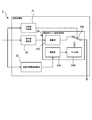
- FIG. 1 is a diagram showing a schematic configuration of a damper control device according to an embodiment of the present invention.
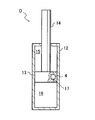
- FIG. 2 is a schematic longitudinal sectional view of the damper.
- FIG. 3 is a diagram illustrating a specific configuration of the damper control device.
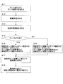
- FIG. 4 is a flowchart showing a control procedure performed by the damper control device.
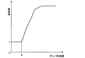
- FIG. 5 is an example of a map in the multiplication value calculation unit.
- FIG. 6 is an example of a map in the subtraction value calculation unit.
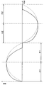
- FIG. 7 is a diagram showing a change with time of the damper speed and the control damper speed.
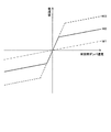
- FIG. 8 is an example of a map for obtaining a current value applied to the damper based on the control damper speed.
- FIG. 1 is a diagram showing a schematic configuration of a damper control device according to an embodiment of the present invention.
- FIG. 2 is a schematic longitudinal sectional view of the damper.
- FIG. 3 is a diagram illustrating a specific
- FIG. 9 is a diagram for explaining a damping force speed characteristic of a damper to which the damper control device according to the embodiment of the present invention is applied and a hysteresis generated in the damping force speed characteristic due to a damping force response delay of the damper.
- FIG. 10 is a diagram illustrating a modification of the damper control device.
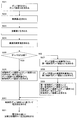
- FIG. 11 is a flowchart illustrating a control procedure performed by the damper control device according to the modification.
- FIG. 12 is a diagram illustrating another modification of the damper control device.
- FIG. 13 is a flowchart illustrating a control procedure performed by a damper control device according to another modification.
- the damper control device E controls the damping force of the damper D interposed between the sprung member B and the unsprung member W in the vehicle, as shown in FIG.
- the damper control device E uses the speed detector 1 for detecting the damper speed Vd, the speed converter 2 for converting the damper speed Vd to the control damper speed Vc, and the damping force of the damper D using the control damper speed Vc.
- a control unit 3 for controlling.
- the speed detector 1 includes a stroke sensor 26 that detects a damper displacement X that is a stroke of the damper D, a differentiator 27 that calculates a damper speed Vd of the damper D by differentiating the damper displacement X detected by the stroke sensor 26, and It has.
- the speed conversion unit 2 includes an acceleration / deceleration determination unit 21 that determines whether the damper D is accelerating or decelerating, a multiplication value calculation unit 22 that calculates a multiplication value k to be multiplied by the damper speed Vd, and a damper speed Vd.
- a subtraction value calculation unit 23 that calculates a subtraction value ⁇ to be subtracted, and a control damper speed calculation unit 24 that calculates a control damper speed Vc based on the determination result of the acceleration / deceleration determination unit 21 are provided.
- the damper D includes a cylinder 12, a piston 13 that is slidably inserted into the cylinder 12, and a piston rod that is movably inserted into the cylinder 12 and connected to the piston 13. 14, two pressure chambers 15, 16 partitioned by a piston in the cylinder 12, a passage 17 communicating with the pressure chambers 15, 16, and damping that provides resistance to the flow of hydraulic fluid as a working fluid passing through the passage 17
- a fluid pressure damper including the force adjusting unit 4.
- the damper D is interposed between the sprung member B and the unsprung member W in parallel with the suspension spring S.
- the damper D applies a resistance to the flow of the hydraulic oil by the damping force adjusting unit 4 to perform the expansion / contraction operation. Demonstrate damping force. Thereby, the relative movement of the sprung member B and the unsprung member W is suppressed.
- the damper D includes a gas chamber and a reservoir for compensating the volume of the piston rod 14 entering and exiting the cylinder 12.
- the working fluid is a gas
- the gas chamber and the reservoir may not be provided.
- damper D when the damper D is provided with a reservoir and is a uniflow damper in which the working fluid is discharged from the cylinder 12 through the passage to the reservoir even when the damper D is extended or contracted, the damper 12 is transferred from the cylinder 12 to the reservoir.
- the damping force adjusting unit 4 may be provided in the middle of the communicating path.
- the damping force adjusting unit 4 includes, for example, a damping valve that makes the flow passage area of the passage 17 variable, and a solenoid or an actuator that can adjust the flow passage area of the passage 17 by driving the valve body of the damping valve. It is prepared for.
- the damper D can adjust the flow path area of the passage 17 by increasing or decreasing the amount of current applied to the solenoid or actuator, and can change the resistance given to the flow of hydraulic oil passing through the passage 17. Thereby, the damping force generated by the damper D can be adjusted.
- the damping force adjustment unit 4 adjusts the damping force generated by the damper D by adjusting the damping coefficient.
- the configuration of the damping force adjusting unit 4 is an example.
- the damper D is configured by filling the pressure chambers 15 and 16 with electrorheological fluid or magnetorheological fluid
- a device capable of applying an electric field or a magnetic field can be used instead of the damping valve to adjust the damping force. What is necessary is just to incorporate in the channel
- FIG. 1 is just to incorporate in the channel
- the generated damping force of the damper D is made variable by changing the viscosity of the fluid flowing through the passage 17 by adjusting the magnitude of the electric field or magnetic field according to the current or voltage supplied from the damper control device E. Can do.
- the damping coefficient is adjusted according to the magnitude of the electric field applied to the passage 17, so that the control is performed by increasing or decreasing the voltage applied to the damping force adjusting unit 4. For this reason, the control part 3 should just obtain
- the damper D may be an electromagnetic damper that exhibits a damping force that suppresses relative movement between the sprung member B and the unsprung member W by electromagnetic force.
- the electromagnetic damper includes, for example, a motor and a motion conversion mechanism that converts the rotational motion of the motor into a linear motion, or is a linear motor.
- the damping force adjustment unit 4 may be a motor driving device that adjusts the current flowing through the motor or linear motor.
- the damper control device E obtains the damper speed Vd by differentiating the damper displacement X detected by the stroke sensor 26 with the fine weapon 27 in the speed detector 1 (S1).
- the speed detection unit 1 inputs the detected damper speed Vd to the speed conversion unit 2.
- the speed detection unit 1 detects the damper speed Vd by setting the direction in which the damper D extends to be positive and, on the other hand, setting the direction in which the damper D contracts to be negative.
- the damper control device E obtains the damper acceleration ⁇ from the damper acceleration Vd obtained in S1 and obtains the multiplication value k from the damper acceleration ⁇ in the multiplication value calculation unit 22 (S2).
- the multiplication value calculation unit 22 has a map regarding the relationship between the absolute value of the damper acceleration ⁇ and the multiplication value k to be multiplied by the damper speed Vd.
- the multiplication value calculation unit 22 obtains the multiplication value k by map calculation using the absolute value of the damper acceleration ⁇ as a parameter.
- the multiplication value k is set so that the lower limit value is 1, and the multiplication value k increases as the absolute value of the damper acceleration ⁇ increases.
- the damper speed Vd is multiplied by the multiplication value k obtained by the multiplication value calculating unit 22 to obtain the control damper speed Vc. Is required.
- the above map can be set arbitrarily.
- the absolute value of the damper acceleration ⁇ is equal to or less than the set value ⁇
- the multiplication value k is set to be 1. Therefore, when the damper D is accelerating and the damper acceleration ⁇ takes a value close to 0, that is, when the rate of change of the speed of the damper D is small, the control damper speed Vc is close to the damper speed Vd. It is supposed to take a value. As a result, during the acceleration of the damper D, the control damper speed Vc always takes a value equal to or higher than the damper speed Vd.
- the increase rate of the multiplication value k with respect to the increase of the damper acceleration ⁇ can be arbitrarily set. If the increase rate of the multiplication value k is set empirically or experimentally so that the control damper speed Vc does not exceed the maximum value that the damper speed Vd will reach when the damper D vibrates. Therefore, it is possible to prevent the control damper speed Vc from being excessively large with respect to the damper speed Vd.
- the set value ⁇ can be set arbitrarily and can be set to 0.
- the map may be set so that the multiplication value k takes 1 when the damper acceleration ⁇ is 0.
- the damper control device E obtains the subtraction value ⁇ from the absolute value of the damper acceleration ⁇ and the damper speed Vd by the subtraction value calculation unit 23 (S3).
- the subtraction value calculation unit 23 determines the sign of the temporary value obtained by the map calculation unit 23a and the map calculation unit 23a, and calculates the subtraction value ⁇ based on the temporary value.
- the map calculation unit 23a holds a map regarding the relationship between the absolute value of the damper acceleration ⁇ and the provisional value.
- the provisional value is a numerical value necessary for obtaining the subtraction value ⁇ to be subtracted from the damper speed Vd.
- the subtraction value calculator 23 obtains a temporary value by map calculation using the absolute value of the damper acceleration ⁇ as a parameter.
- the provisional value is set to take a positive value.
- requiring a temporary value can be set arbitrarily. As shown in FIG. 6, the provisional value is set to increase as the absolute value of the damper acceleration ⁇ increases.
- the sign determination unit 23b multiplies 1 to obtain the subtraction value ⁇ in order to make the sign of the provisional value positive.
- the subtraction value ⁇ is obtained by multiplying by ⁇ 1 to make the sign of the provisional value negative.
- the damper control device E determines whether the damper D is accelerating or decelerating from the sign of the damper speed Vd and the sign of the damper acceleration ⁇ at the acceleration / deceleration judging unit 21 (S4).
- the acceleration of the damper D means that the change rate of the absolute value of the damper speed Vd is positive, and the deceleration of the damper D means that the change rate of the absolute value of the damper speed Vd is negative. is there. That is, the acceleration / deceleration determination unit 21 determines that the damper D is accelerating in a situation where the absolute value of the damper speed Vd increases with time, and in a situation where the absolute value of the damper speed Vd decreases over time, It is determined that the damper D is decelerating.
- the damper D When the damper speed Vd takes a positive value, the damper D is accelerating when the damper speed Vd is increasing, and the damper D is decelerating when the damper speed Vd is the value of the damper speed Vd. Is in a decreasing state. In addition, when the damper speed Vd takes a negative value, the damper D is accelerating when the damper speed Vd is increasing in the negative direction, and the damper D is decelerating. In this state, the value of the damper speed Vd is decreasing in the positive direction. Therefore, whether the damper D is accelerating or decelerating can be determined from the sign of the damper speed Vd and the sign of the damper acceleration ⁇ .
- the acceleration / deceleration determining unit 21 determines that the damper D is accelerating when the product value of the damper acceleration ⁇ and the damper speed Vd obtained by differentiating the damper speed Vd is positive. If the product value of the damper acceleration ⁇ and the damper speed Vd is negative, it is determined that the damper D is decelerating.
- the damper displacement X has a phase opposite to that of the damper acceleration ⁇ , it can be determined whether the damper D is accelerating or decelerating based on the sign of the damper displacement X and the sign of the damper speed Vd. . When the value of the product is 0, it may be determined that the damper D is accelerating or may be determined to be decelerating.
- the acceleration / deceleration determination unit 21 may determine whether the damper D is accelerating or decelerating based on the sign of the damper displacement X and the sign of the damper speed Vd.
- the damper speed calculator 24 controls the damper speed so that the signs of the control damper speed Vc and the damper speed Vd match.
- a control damper speed Vc is obtained from Vd and the multiplication value k obtained in S2 (S5). If it is determined in S4 that the damper D is decelerating, the damper speed Vd and S3 are set so that the control damper speed calculator 24 matches the signs of the damper speed Vd and the damper speed Vd.
- a control damper speed Vc is obtained from the obtained subtraction value ⁇ (S6).
- the control damper speed calculation unit 24 includes a multiplication unit 24 b that multiplies the damper value Vd by the multiplication value k, a subtraction unit 24 c that subtracts the subtraction value ⁇ from the damper speed Vd, A selection unit 24a that selects one of the path of the multiplication unit 24b and the path of the subtraction unit 24c based on the determination result of the acceleration / deceleration determination unit 21, and the sign of the calculation result of the subtraction part 24c is the sign of the damper speed Vd And a limiter unit 24d that outputs the value of the calculation result of the subtraction unit 24c as it is when the codes match.
- the selection unit 24a selects the path of the multiplication unit 24b based on the determination result.
- the multiplier 24b multiplies the damper speed Vd by the multiplication value k obtained by the multiplication value calculator 22, and outputs a control damper speed Vc.
- the selection unit 24a selects the path of the subtraction unit 24c in response to the determination result.
- the subtraction unit 24c outputs a value obtained by subtracting the subtraction value ⁇ from the damper speed Vd to the limiter unit 24d.
- the limiter unit 24d When the sign of the damper speed Vd and the sign of the value obtained by the calculation of the subtracting part 24c are the same, the limiter unit 24d outputs the value as it is as the control damper speed Vc. Further, when the sign of the damper speed Vd and the sign of the value obtained by the calculation of the subtracting unit 24c are different, the control damper speed Vc is output as 0.
- the control damper speed Vc is obtained by subtracting the subtracted value ⁇ from the damper speed Vd, so that the control damper speed Vc is earlier in time than the damper speed Vd becomes zero. Becomes 0.
- the sign of the damper speed Vd and the sign of the value obtained by the calculation of the subtracting unit 24c are different, the control damper speed Vc is limited to 0, and the direction of the control damper speed Vc is the same as the damper speed Vd. Inversion against the direction is prevented.
- the control damper speed Vc converted from the damper speed Vd does not indicate the contraction of the damper D. Further, when the damper D is contracted, the converted control damper speed Vc does not indicate the extension of the damper D.
- the damper control device E causes the speed converter 2 to make the sign coincide with the sign of the damper speed Vd when the damper D is accelerating, and the absolute value is the damper speed.
- the damper speed Vd is converted into a control damper speed Vc so that the absolute value of Vd is greater than or equal to Vd.
- the damper speed Vd is made to coincide with the sign of the damper speed Vd, and the damper speed Vd is set to the control damper speed Vc so that the absolute value is equal to or less than the absolute value of the damper speed Vd. Convert to
- the damper control device E obtains a current value I as a control command value to be given to the damping force adjusting unit 4 based on the control damper speed Vc in the control unit 3 (S7).
- control unit 3 adjusts the damping coefficient of the damper D according to the amount of current supplied to the damping force adjustment unit 4.
- the control command output by the control unit 3 is input to a driver 5 that supplies current to the solenoid of the damping force adjustment unit 4.
- the driver 5 controls the damping force of the damper D by supplying current to the damping force adjusting unit 4 according to the current value I obtained in S7 (S8).
- the driver 5 includes, for example, a PWM circuit and can supply current to the damping force adjusting unit 4 according to the current value I input from the control unit 3.
- the control unit 3 has a plurality of maps of the current value I that changes using the control damper speed Vc as a parameter in order to realize three damping characteristics of soft, medium, and hard.
- the control unit 3 selects a map based on the vibration intensity of the unsprung member W in the vehicle, and performs a map calculation using the control damper speed Vc. Then, a control command is output to the driver 5 in order to output a current according to the obtained current value I.
- the vibration intensity of the unsprung member W is the magnitude of vibration of the unsprung member W.
- the length of the combined vector of the damper acceleration ⁇ and the damper speed Vd divided by the angular frequency value or the length of the combined vector of the damper displacement X and the damper speed Vd multiplied by the angular frequency value is obtained. Can do.
- the map is set such that as the vibration intensity increases, the damping force increases with respect to the control damper speed Vc, that is, the current value I increases.
- the vibration strength is divided into large, medium and small categories according to the magnitude of the vibration strength, and a map corresponding to each category is prepared.
- the control unit 3 selects a map corresponding to the small category, that is, a map M1 having a damping characteristic as a soft characteristic from the map group. Then, using the selected map M1, a current value I that is a control command value is obtained using the control damper speed Vc.
- the control unit 3 selects a map corresponding to the classification, that is, a map M2 having a damping characteristic as a medium characteristic from the map group. Then, using the selected map M2, a current value I which is a control command value is obtained using the control damper speed Vc.
- the control unit 3 selects a map corresponding to the large category, that is, a map M3 having a damping characteristic as a hard characteristic from the map group. Then, using the selected map M3, a current value I which is a control command value is obtained using the control damper speed Vc.
- control unit 3 may employ skyhook control to generate a control command to be given to the driver 5 from the control damper speed Vc.
- the Karnop switching rule can also be used for skyhook control. Note that the map calculation may be performed to obtain the control command, or the map calculation may not be performed when the control command can be obtained without performing the map calculation.
- the damping force adjustment unit 4 adjusts the damping coefficient in the damper D by receiving a current amount according to the current value I from the driver 5. At this time, the damper D exhibits a damping force according to the control damper speed Vc, not the damper speed Vd. In this way, the damping force of the damper D is controlled by the damper control device E.
- the damper control device E converts the damper speed Vd into a control damper speed Vc that is equal to or higher than the damper speed Vd.
- the damping force of the damper D is controlled by the converted control damper speed Vc.
- the damper speed Vd has the same sign as the damper speed Vd, and the absolute value is equal to or greater than the absolute value of the damper speed Vd. , Converted to a control damper speed Vc.
- the converted control damper speed Vc changes as if the phase was advanced in time with respect to the damper speed Vd. However, it does not change so that the phase is completely advanced with respect to the damper speed Vd. When the damper D is accelerating, it does not fall below the damper speed Vd until the damper acceleration ⁇ starts to decrease.
- the damper speed Vd is made to have the same sign as the damper speed Vd, and the absolute value is equal to or less than the absolute value of the damper speed Vd. Thus, it is converted into a control damper speed Vc.
- the converted control damper speed Vc changes as if the phase was advanced in time with respect to the damper speed Vd. However, it does not change so that the phase is completely advanced with respect to the damper speed Vd. When the damper D is decelerating, it does not exceed the damper speed Vd until the damper acceleration ⁇ starts to increase.
- the control damper speed Vc advances in time with respect to the damper speed Vd that is the actual speed of the damper D.
- the time delay of the damping force response of the damper D is canceled out. Therefore, as indicated by a solid line in FIG. 9, the hysteresis in the damping characteristic of the damper D (the characteristic of the damping force generated by the damper D with respect to the damper speed) can be made extremely small.
- the damper control device E of the present embodiment it is possible to suppress the occurrence of hysteresis in the damping force of the damper D and to improve the riding comfort in the vehicle.
- phase of the control damper speed Vc is not simply advanced with respect to the damper speed Vd, but the control damper speed Vc and the speed direction of the damper speed Vd are always matched. Therefore, when the damper D decelerates and the damper speed Vd approaches 0, the absolute value of the control damper speed Vc increases with the sign of the control damper speed Vc reversed, and the damping force generated by the damper D Can be prevented from becoming large.
- the damper control device E of the present embodiment when the damper speed Vd approaches 0 during deceleration, it is possible to prevent the damping force from increasing and deteriorating the riding comfort in the vehicle. .
- the hysteresis of the damper D appears prominently when the damping characteristic of the damper D is controlled so that the damping coefficient when the damper speed Vd is in the low speed region is higher than the damping coefficient when the damper speed Vd is in the high speed region.
- the damping force of the damper D is controlled so that the damping coefficient when the damper speed Vd is in the low speed region is higher than the damping coefficient when in the high speed region. Only in this case, the control using the control damper speed Vc may be executed as described above. Even in this case, the hysteresis of the damper D can be reduced.
- the damper speed Vd is converted into the control damper speed Vc so that the difference between the damper speed Vd and the control damper speed Vc increases as the absolute value of the damper acceleration ⁇ increases. Yes.
- the control damper speed Vc can be temporally advanced with respect to the damper speed Vd in a scene where the speed change of the damper D is severe, the hysteresis of the damping force of the damper D can be reduced more effectively. be able to.
- the control damper speed Vc can be set to 0 earlier in time than the damper speed Vd becomes 0, and the hysteresis can be further reduced.
- the control damper speed Vc is obtained by subtracting the subtraction value ⁇ from the damper speed Vd.
- a deceleration multiplication value calculation unit 25 for obtaining a deceleration multiplication value j having a value of 0 or more and 1 or less is provided, and instead of the subtraction unit 24c, the damper speed Vd is multiplied by the deceleration multiplication value j. It is also possible to obtain the control damper speed Vc by providing the multiplication unit 24e that multiplies and multiplying the damper speed Vd by the deceleration multiplication value j.
- the damper control device E performs control according to the procedure shown in the flowchart of FIG.
- the damper control device E obtains the damper speed Vd and the multiplication value k similarly to S1 and S2 in the above embodiment (S11, S12).
- the damper control device E obtains the deceleration multiplication value j from the damper speed Vd by the deceleration multiplication value calculation unit 25 (S13).
- the damper control device E determines whether the damper D is accelerating or decelerating (S14), similarly to S4 in the above embodiment.
- the damper control device E determines that the damper D is accelerating in S14, the damper speed Vc and the damper speed Vd are matched so that the signs of the damper speed Vd and the damper speed Vd are the same as in S5 in the above embodiment.
- a control damper speed Vc is obtained from Vd and the multiplication value k obtained in S12 (S15). If it is determined in S14 that the damper D is decelerating, the multiplying unit 24e uses the damper speed Vd and the deceleration speed obtained in S13 so that the signs of the control damper speed Vc and the damper speed Vd match.
- a control damper speed Vc is obtained from the multiplication value j (S16).
- damper control apparatus E calculates
- a deceleration multiplication value calculation unit 25 is provided.
- the damper speed Vd, the subtraction value ⁇ , and the deceleration A calculation unit 24f that obtains the control damper speed Vc from the product multiplication value j may be provided.
- the damper control device E performs control according to the procedure shown in the flowchart of FIG.
- the damper control device E obtains the damper speed Vd, the multiplication value k, and the subtraction value ⁇ , similarly to S1 to S3 in the above embodiment (S21 to S23). Further, similarly to S13 in the embodiment shown in FIG. 10, a deceleration multiplication value j is obtained (S24).
- the damper control device E determines whether the damper D is accelerating or decelerating (S25), similarly to S4 in the above embodiment.
- damper control device E determines that the damper D is accelerating in S25, the damper speed Vc and the damper speed Vd are matched so that the signs of the control damper speed Vc and the damper speed Vd are the same as in S5 in the above embodiment.
- a control damper speed Vc is obtained from Vd and the multiplication value k obtained in S22 (S26).
- the calculation unit 24f subtracts the subtraction value ⁇ from the damper speed Vd to obtain the first control damper speed Vc1 (S27), and the deceleration multiplication
- the value j is multiplied by the damper speed Vd to obtain the second control damper speed Vc2 (S28), and the control damper speed Vc and the damper speed Vd are determined from the first control damper speed Vc1 and the second control damper speed Vc2.
- the control damper speed Vc is obtained so that the signs coincide (S29).
- any one of the first control damper speed Vc1 and the second control damper speed Vc2 may be adopted as the control damper speed Vc used for control, or the first control damper speed Vc1 may be used.
- a value obtained by averaging the speed Vc1 and the second control damper speed Vc2 may be employed, or a value obtained by multiplying the weights and adding them may be employed.
- damper control apparatus E calculates
- the damper speed Vd is not multiplied by the multiplication value k to obtain the control damper speed Vc, but an addition value having a value of 1 or more is obtained and the damper speed Vd is added to the addition value. May be added to obtain the control damper speed Vc.
- the speed conversion unit 2 converts the damper speed Vd into the control damper speed Vc, so that the sign of the damper speed Vd and the sign of the control damper speed Vc are different.
- the control damper speed Vc is set to 0, but it may be set to a predetermined value whose sign coincides with the damper speed Vd. According to this, similarly to the case where the control damper speed Vc is set to 0, when the damper D decelerates and the damper speed Vd approaches 0, the control damper speed Vc is in the state where the sign of the control damper speed Vc is reversed. It can be prevented that the absolute value of the damper speed Vc increases and the damping force generated by the damper D increases. If the predetermined value is set to a small value close to 0, it is advantageous in reducing the hysteresis of the damping force.
- the predetermined value may be a value that changes according to the damper speed Vd.
Landscapes
- Engineering & Computer Science (AREA)
- Mechanical Engineering (AREA)
- Vehicle Body Suspensions (AREA)
Abstract
Description
Claims (9)
- 車両におけるばね上部材とばね下部材との間に介装されるダンパの減衰力をダンパ速度に基づいて制御するダンパ制御装置であって、
前記ダンパ速度を制御用ダンパ速度に変換する速度変換部を備え、
前記速度変換部は、前記ダンパが加速している場合には、前記制御用ダンパ速度と前記ダンパ速度との符号が一致するようにするとともに、前記制御用ダンパ速度の絶対値が前記ダンパ速度の絶対値以上となるように前記ダンパ速度を変換し、前記ダンパが減速している場合には、前記制御用ダンパ速度と前記ダンパ速度との符号が一致するようにするとともに、前記制御用ダンパ速度の絶対値が前記ダンパ速度の絶対値以下となるように前記ダンパ速度を変換し、
前記速度変換部で求めた前記制御用ダンパ速度を用いて前記ダンパの減衰力を制御するダンパ制御装置。 - 請求項1に記載のダンパ制御装置であって、
前記速度変換部は、ダンパ加速度に基づいて前記ダンパ速度を変換するダンパ制御装置。 - 請求項2に記載のダンパ制御装置であって、
前記速度変換部は、前記ダンパ加速度が大きいほど、大きくダンパ速度を変換するダンパ制御装置。 - 請求項1に記載のダンパ制御装置であって、
前記速度変換部は、前記ダンパ速度が減速している場合に前記ダンパ速度を前記制御用ダンパ速度に変換した結果、前記ダンパ速度の符号と前記制御用ダンパ速度の符号とが異なる場合は、前記制御用ダンパ速度を前記ダンパ速度と符号が一致する所定値または0とするダンパ制御装置。 - 請求項1に記載のダンパ制御装置であって、
前記速度変換部は、前記ダンパが加速しているか減速しているかを判断する加減速判断部を備え、前記加減速判断部が前記ダンパが減速していると判断した場合は、前記ダンパ速度から減算値を減算して前記制御用ダンパ速度を求めるダンパ制御装置。 - 請求項1に記載のダンパ制御装置であって、
前記速度変換部は、
前記ダンパが加速しているか減速しているかを判断する加減速判断部と、
前記ダンパが加速している場合に前記ダンパ速度に乗算すべき乗算値を求める乗算値演算部と、
前記ダンパが減速している場合に前記ダンパ速度から減算すべき減算値を求める減算値演算部と、
前記加減速判断部が前記ダンパが加速していると判断した場合は、前記ダンパ速度に前記乗算値を乗じて前記制御用ダンパ速度を求め、前記ダンパが減速していると判断した場合は、前記ダンパ速度から前記減算値を減算して前記制御用ダンパ速度を求める制御用ダンパ速度演算部と、
を備えるダンパ制御装置。 - 請求項1に記載のダンパ制御装置であって、
前記速度変換部は、
前記ダンパが加速しているか減速しているかを判断する加減速判断部と、
前記ダンパが加速している場合に前記ダンパ速度に乗算すべき乗算値を求める乗算値演算部と、
前記ダンパが減速している場合に前記ダンパ速度に乗算すべき0以上1以下の減速用乗算値を求める減速用乗算値演算部と、
前記加減速判断部が前記ダンパが加速していると判断した場合は、前記ダンパ速度に前記乗算値を乗じて前記制御用ダンパ速度を求め、前記ダンパが減速していると判断した場合は、前記ダンパ速度に前記減速用乗算値を乗算して前記制御用ダンパ速度を求める制御用ダンパ速度演算部と、
を備えるダンパ制御装置。 - 請求項1に記載のダンパ制御装置であって、
前記速度変換部は、
前記ダンパが加速しているか減速しているかを判断する加減速判断部と、
前記ダンパが加速している場合に前記ダンパ速度に乗算すべき乗算値を求める乗算値演算部と、
前記ダンパが減速している場合に前記ダンパ速度から減算すべき減算値を求める減算値演算部と、
前記ダンパが減速している場合に前記ダンパ速度に乗算すべき0以上1以下の減速用乗算値を求める減速用乗算値演算部と、
前記加減速判断部が前記ダンパが加速していると判断した場合は、前記ダンパ速度に前記乗算値を乗じて前記制御用ダンパ速度を求め、前記ダンパが減速していると判断した場合は、前記ダンパ速度から前記減算値を減算して第一制御用ダンパ速度を求めるとともに前記ダンパ速度に前記減速用乗算値を乗算して第二制御用ダンパ速度を求めて、前記第一制御用ダンパ速度と前記第二制御用ダンパ速度とに基づいて前記制御用ダンパ速度を求める制御用ダンパ速度演算部と、
を備えるダンパ制御装置。 - 請求項1に記載のダンパ制御装置であって、
ダンパ速度が低速領域にある際の減衰係数が高速領域にある際の減衰係数よりも高くなるように前記ダンパの減衰力を制御する場合には、前記制御用ダンパ速度を用いて前記ダンパの減衰力を制御するダンパ制御装置。
Priority Applications (3)
| Application Number | Priority Date | Filing Date | Title |
|---|---|---|---|
| JP2015513842A JP6349308B2 (ja) | 2013-04-25 | 2014-04-24 | ダンパ制御装置 |
| DE112014002136.9T DE112014002136T5 (de) | 2013-04-25 | 2014-04-24 | Dämpferregelvorrichtung |
| US14/780,027 US9718324B2 (en) | 2013-04-25 | 2014-04-24 | Damper control device |
Applications Claiming Priority (2)
| Application Number | Priority Date | Filing Date | Title |
|---|---|---|---|
| JP2013-091885 | 2013-04-25 | ||
| JP2013091885 | 2013-04-25 |
Publications (1)
| Publication Number | Publication Date |
|---|---|
| WO2014175406A1 true WO2014175406A1 (ja) | 2014-10-30 |
Family
ID=51791972
Family Applications (1)
| Application Number | Title | Priority Date | Filing Date |
|---|---|---|---|
| PCT/JP2014/061636 Ceased WO2014175406A1 (ja) | 2013-04-25 | 2014-04-24 | ダンパ制御装置 |
Country Status (4)
| Country | Link |
|---|---|
| US (1) | US9718324B2 (ja) |
| JP (1) | JP6349308B2 (ja) |
| DE (1) | DE112014002136T5 (ja) |
| WO (1) | WO2014175406A1 (ja) |
Families Citing this family (1)
| Publication number | Priority date | Publication date | Assignee | Title |
|---|---|---|---|---|
| GB2579510B (en) * | 2017-07-19 | 2021-10-13 | Takahashi Kota | Signal generator for generating power change signal to drive speaker, speaker |
Citations (4)
| Publication number | Priority date | Publication date | Assignee | Title |
|---|---|---|---|---|
| JP2005075238A (ja) * | 2003-09-02 | 2005-03-24 | Toyota Motor Corp | 車両用サスペンション装置 |
| JP2009132237A (ja) * | 2007-11-29 | 2009-06-18 | Toyota Motor Corp | サスペンションシステム |
| JP2011131876A (ja) * | 2009-11-30 | 2011-07-07 | Hitachi Automotive Systems Ltd | 車両用サスペンション制御装置 |
| JP2011230718A (ja) * | 2010-04-29 | 2011-11-17 | Hitachi Automotive Systems Ltd | 車両用サスペンション制御装置 |
Family Cites Families (13)
| Publication number | Priority date | Publication date | Assignee | Title |
|---|---|---|---|---|
| JP3083116B2 (ja) * | 1991-12-26 | 2000-09-04 | 株式会社ユニシアジェックス | 車両懸架装置 |
| US5712783A (en) * | 1996-04-26 | 1998-01-27 | Lord Corporation | Control method for semi-active damper |
| JP3689829B2 (ja) * | 1996-10-04 | 2005-08-31 | 株式会社日立製作所 | サスペンション制御装置 |
| KR100550070B1 (ko) * | 2003-11-26 | 2006-02-08 | 주식회사 만도 | 전자 제어 현가 장치와 이를 이용한 댐퍼 감쇠력 제어 방법 |
| KR100574898B1 (ko) * | 2003-11-26 | 2006-04-27 | 주식회사 만도 | 전자 제어 현가 장치와 이를 이용한 감쇠력 제어 방법 |
| JP4546308B2 (ja) * | 2005-03-30 | 2010-09-15 | 本田技研工業株式会社 | 可変減衰力ダンパーの制御装置 |
| JP5001585B2 (ja) | 2006-01-16 | 2012-08-15 | 本田技研工業株式会社 | 可変減衰力ダンパの制御装置 |
| US7340334B2 (en) * | 2006-06-07 | 2008-03-04 | Honda Motor Co., Ltd. | Control device of variable damping force damper |
| US8090500B2 (en) * | 2006-12-06 | 2012-01-03 | Honda Motor Co., Ltd. | Control device for a variable damper |
| JP5093490B2 (ja) * | 2008-05-20 | 2012-12-12 | 日立オートモティブシステムズ株式会社 | サスペンション制御装置 |
| JP5246269B2 (ja) * | 2008-12-25 | 2013-07-24 | トヨタ自動車株式会社 | 減衰力制御装置 |
| EP2452841B1 (en) * | 2009-07-08 | 2017-10-18 | Toyota Jidosha Kabushiki Kaisha | Vehicular damper system |
| JP5839443B2 (ja) * | 2011-05-31 | 2016-01-06 | 日立オートモティブシステムズ株式会社 | サスペンション制御装置 |
-
2014
- 2014-04-24 DE DE112014002136.9T patent/DE112014002136T5/de not_active Withdrawn
- 2014-04-24 US US14/780,027 patent/US9718324B2/en not_active Expired - Fee Related
- 2014-04-24 JP JP2015513842A patent/JP6349308B2/ja not_active Expired - Fee Related
- 2014-04-24 WO PCT/JP2014/061636 patent/WO2014175406A1/ja not_active Ceased
Patent Citations (4)
| Publication number | Priority date | Publication date | Assignee | Title |
|---|---|---|---|---|
| JP2005075238A (ja) * | 2003-09-02 | 2005-03-24 | Toyota Motor Corp | 車両用サスペンション装置 |
| JP2009132237A (ja) * | 2007-11-29 | 2009-06-18 | Toyota Motor Corp | サスペンションシステム |
| JP2011131876A (ja) * | 2009-11-30 | 2011-07-07 | Hitachi Automotive Systems Ltd | 車両用サスペンション制御装置 |
| JP2011230718A (ja) * | 2010-04-29 | 2011-11-17 | Hitachi Automotive Systems Ltd | 車両用サスペンション制御装置 |
Also Published As
| Publication number | Publication date |
|---|---|
| JPWO2014175406A1 (ja) | 2017-02-23 |
| US20160052360A1 (en) | 2016-02-25 |
| DE112014002136T5 (de) | 2016-01-07 |
| US9718324B2 (en) | 2017-08-01 |
| JP6349308B2 (ja) | 2018-06-27 |
Similar Documents
| Publication | Publication Date | Title |
|---|---|---|
| CN102729761B (zh) | 悬架装置 | |
| JP6510796B2 (ja) | サスペンション装置およびサスペンション制御装置 | |
| WO2020075455A1 (ja) | サスペンション制御装置 | |
| EP3216634A1 (en) | Suspension device and suspension control device | |
| JP2008012960A (ja) | 緩衝器の制御装置 | |
| KR102304144B1 (ko) | 서스펜션에서의 댐퍼 마찰 효과들의 제어 | |
| US10696119B2 (en) | Control apparatus of damping force variable damper, control system, and method | |
| JP5746246B2 (ja) | ダンパ制御装置 | |
| WO2016056518A1 (ja) | 緩衝器 | |
| JP6349308B2 (ja) | ダンパ制御装置 | |
| JP6132859B2 (ja) | サスペンション装置 | |
| EP3213942A1 (en) | Damper control apparatus | |
| JP5702200B2 (ja) | 緩衝器の制御装置 | |
| KR20180054803A (ko) | 진동 댐퍼, 진동 댐퍼의 작동 방법, 제어 장치, 및 자동차 | |
| JP5608057B2 (ja) | サスペンション装置 | |
| JP7161958B2 (ja) | サスペンション装置及びその制御方法 | |
| JP6059564B2 (ja) | ダンパ速度検知装置 | |
| JP4546323B2 (ja) | 可変減衰力ダンパー | |
| JP2012148734A (ja) | サスペンション装置 | |
| JP6838785B2 (ja) | サスペンション制御装置 | |
| JP5503511B2 (ja) | サスペンション装置 | |
| JP2006264367A (ja) | 緩衝器の制御装置 | |
| JP2006273220A (ja) | 可変減衰力ダンパーの制御装置 | |
| KR20120002756A (ko) | 연속 가변 제어 댐퍼의 제어 방법 |
Legal Events
| Date | Code | Title | Description |
|---|---|---|---|
| 121 | Ep: the epo has been informed by wipo that ep was designated in this application |
Ref document number: 14788160 Country of ref document: EP Kind code of ref document: A1 |
|
| ENP | Entry into the national phase |
Ref document number: 2015513842 Country of ref document: JP Kind code of ref document: A |
|
| WWE | Wipo information: entry into national phase |
Ref document number: 14780027 Country of ref document: US |
|
| WWE | Wipo information: entry into national phase |
Ref document number: 112014002136 Country of ref document: DE Ref document number: 1120140021369 Country of ref document: DE |
|
| 122 | Ep: pct application non-entry in european phase |
Ref document number: 14788160 Country of ref document: EP Kind code of ref document: A1 |