WO2014175017A1 - 金属平板部材の接合構造 - Google Patents
金属平板部材の接合構造 Download PDFInfo
- Publication number
- WO2014175017A1 WO2014175017A1 PCT/JP2014/059632 JP2014059632W WO2014175017A1 WO 2014175017 A1 WO2014175017 A1 WO 2014175017A1 JP 2014059632 W JP2014059632 W JP 2014059632W WO 2014175017 A1 WO2014175017 A1 WO 2014175017A1
- Authority
- WO
- WIPO (PCT)
- Prior art keywords
- flat plate
- metal flat
- rotation preventing
- plate members
- plate member
- Prior art date
- Legal status (The legal status is an assumption and is not a legal conclusion. Google has not performed a legal analysis and makes no representation as to the accuracy of the status listed.)
- Ceased
Links
Images




Classifications
-
- B—PERFORMING OPERATIONS; TRANSPORTING
- B21—MECHANICAL METAL-WORKING WITHOUT ESSENTIALLY REMOVING MATERIAL; PUNCHING METAL
- B21D—WORKING OR PROCESSING OF SHEET METAL OR METAL TUBES, RODS OR PROFILES WITHOUT ESSENTIALLY REMOVING MATERIAL; PUNCHING METAL
- B21D39/00—Application of procedures in order to connect objects or parts, e.g. coating with sheet metal otherwise than by plating; Tube expanders
- B21D39/03—Application of procedures in order to connect objects or parts, e.g. coating with sheet metal otherwise than by plating; Tube expanders of sheet metal otherwise than by folding
- B21D39/031—Joining superposed plates by locally deforming without slitting or piercing
Definitions
- the present invention relates to a joint structure of metal flat plate members, and more particularly to a joint structure using a mechanical clinch.
- a conductive member used for an electric connection box etc. of a car As a conductive member used for an electric connection box etc. of a car, a bus bar, a tab terminal etc. which were formed by press punching a metal flat plate are widely adopted, and by joining these metal flat members at appropriate places, Various types of energization circuits are configured.
- Patent Document 1 proposes a structure for caulking and fixing the other metal flat plate member (tab terminal) to (bus bar).
- the tab terminal is superimposed on the bus bar, and only a part of the base end portion of the tab terminal is pushed into the bus bar main body side and caulked.
- the tab terminal may be displaced or detached.
- Patent Document 2 an adhesive containing fine particulate solid is interposed between the overlapping surfaces of the metal flat plate members, and the overlapping portions of the metal flat plate members are A structure is also proposed in which bonding is performed by mechanical clinching which is locally pushed by a punch with the backrest as a backrest. According to this, it is possible to improve the bonding strength of the whole by mechanical clinching, and since a large number of mechanical engaging parts are formed by the fine particulate solid biting into the metal flat plate member, the rotational direction It is possible to prevent rotation by exerting sufficient resistance against the load of
- the present invention has been made against the background described above, and the problem to be solved is a bonding structure of a novel metal flat plate member capable of improving the bonding strength between metal flat plate members with a simple structure. To provide.
- a joint structure of metal flat plate members for joining overlapping portions of two metal flat plate members, wherein the overlapping portions are joined by a joint formed by mechanical clinching.
- at least one of the two metal flat plate members is provided with a rotation preventing protrusion which protrudes in the same direction as the protruding direction of the joint portion and engages with the other of the two metal flat plate members.
- At least one of the metal flat plate members is provided with the rotation preventing projection that protrudes in the same direction as the protruding direction of the bonding portion formed by mechanical clinch, so the joint portion of the metal flat plate member is
- the rotation preventing projection is engaged with the other metal flat plate member to prevent the rotation.
- the rotation preventing projection may be any as long as it can prevent displacement in the assumed rotational direction, and the formation location, shape, number, etc. can be set arbitrarily.
- the rotation preventing projection may be provided only on one of the metal flat plate members in a portion out of the overlapping portion of the metal flat plate members, or may be provided on both metal flat plate members in the overlapping portion.
- the rotation preventing projection is formed by extrusion simultaneously with the joint portion by the mechanical clinch.
- the rotation preventing projection is formed by the extrusion processing performed simultaneously with the joint by mechanical clinch, it is possible to advantageously realize cost reduction and improvement of the workability by shortening the working time. it can.
- a third aspect of the present invention is the one according to the first or second aspect, wherein the anti-rotational protrusion is at a portion outside the overlapping portion of the two flat metal members. It projects from the metal flat plate member and is engaged with the peripheral portion of the other metal flat plate member.
- the rotation preventing protrusion can be provided in a region other than the overlapping portion of the flat metal members as the formation portion of the rotation preventing protrusion, the rotation preventing protrusion is advantageous even when the area of the overlapping portion is small. Can be provided.
- the rotation preventing projections provided on one metal flat plate member are engaged with the peripheral portion of the other metal flat plate member, the rotation preventing force of the metal flat plate member can be reliably exerted.
- the rotation preventing projection is provided so as to project from the overlapping portion of the two metal flat plate members.
- the rotation preventing projection is provided so as to project at a position that is not coaxial with the joint portion of the overlapping portion.
- the rotation preventing projection has a non-circular shape and protrudes in a plan view.
- the rotation preventing projection is projected in a non-circular shape in plan view.
- At least one metal flat plate member is provided with the rotation preventing protrusion projecting in the same direction as the protruding direction of the joint formed by mechanical clinch, so the rotation preventing protrusion is the other metal.
- the engagement with the flat member prevents rotation.
- the joint strength in the rotational direction can be stably ensured, and the joint strength of the metal flat plate member can be reliably improved.
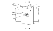
- FIG. 2 is a plan view of the bonded structure of the metal flat plate member shown in FIG. 1.
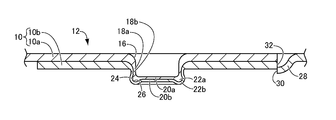
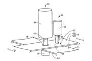
- the III-III cross section enlarged view of FIG. The perspective view which shows the joining process by the mechanical clinch of the joining structure of the metal flat plate member shown in FIG.
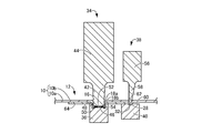
- FIG. 5 is a cross-sectional view taken along line VV of FIG. 4.
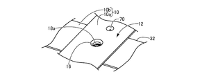
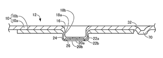
- FIG. 7 is a plan view of the joint structure of the flat metal members shown in FIG. 6.
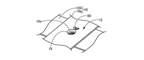
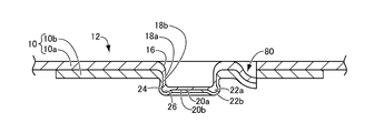
- FIG. 10 is a plan view of the bonded structure of the metal flat plate shown in FIG. 9; The XI-XI cross section enlarged view of FIG.
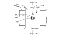
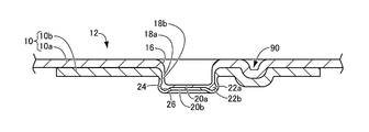
- FIG. 13 is a plan view of the bonded structure of the metal flat plate member shown in FIG. 12. The XIV-XIV cross section enlarged view of FIG.
- 1 to 5 show a structure for joining overlapping portions 12 of two flat metal members 10 using the joint structure of flat metal members 10 according to an embodiment of the present invention.
- FIGS. 1 to 3 show a bonding structure of a flat metal member 10 according to an embodiment of the present invention.
- the metal flat plate member 10 is used, for example, as a conducting member such as a bus bar or a tab terminal, and is formed by, for example, press punching and bending a metal plate such as copper or copper alloy using conventionally known techniques. There is. And electric conduction circuit of various shape is constituted by joining metal flat plate members 10 comrades in an appropriate place.
- the two flat metal members 10 are composed of one upper flat metal member 10a and the other lower flat metal member 10b.
- the two metal flat plate members 10a and 10b are overlapped in the direction orthogonal to each other.
- the superposition part 12 is joined by the joined part 16 formed of mechanical clinch.
- the upper side means the upper side in FIG. 3 and the lower side means the lower side in FIG.
- a cylindrical joint 16 is formed at the center of the overlapping portion 12 of the two flat metal members 10a and 10b.
- the joint portion 16 is constituted by bottomed cylindrical portions 18a and 18b in which two flat metal members 10a and 10b have substantially the same shape and project downward in a cylindrical shape.
- the outer peripheral edge portions of the bottom portions 20a and 20b of the bottomed cylindrical portions 18a and 18b protrude annularly toward the diagonally outward direction, and are provided with annular projections 22a and 22b.
- the outer diameter of the bottomed cylindrical portion 18a of one metal flat plate member 10a is expanded on the side of the bottom portion 20a by the annular projections 22a and 22b, and an annular engagement convex portion 24 is formed.
- the inner diameter of the bottomed cylindrical portion 18b of the other metal flat plate member 10b is expanded on the bottom portion 20b side to form an annular engagement recess 26. Then, the two metal flat plate members 10a and 10b are joined by the engagement of the engagement convex portion 24 and the engagement concave portion 26.
- the part of the metal flat plate member 10a located on the upper side, apart from the overlapping part 12, has a semicircular shape which is non-circular in plan view in the same direction as the protruding direction of the bonding part 16
- a rotation preventing projection 28 is provided to project in a semi-dome shape in a partial spherical shell shape.
- the rotation preventing projection 28 is adapted to engage with the peripheral edge portion 32 of the other metal flat plate member 10 b positioned below at the dome-shaped projecting end surface 30.
- the joint forming punch 34 and the joint forming die 36 for forming the joint 16 and the rotation preventing projection forming punch 38 for forming the rotation preventing projection 28 and the rotation preventing projection are formed.
- a die 40 is prepared.
- the joint forming punch 34 has a cylindrical shape, and the distal end portion 42 has a diameter smaller than that of the proximal end portion 44. Further, the tip end surface 46 of the junction forming punch 34 is substantially flat.
- the bonding portion forming die 36 has a cylindrical shape, and a recess 50 is formed in the tip end surface 48.
- the recess 50 has a substantially bottomed cylindrical shape that opens upward, and a central portion of the bottom surface 52 is substantially flat, while an annular groove 54 is formed in the outer peripheral edge portion of the bottom surface 52.
- the inner diameter of the recess 50 is formed to have a predetermined size slightly larger than the outer diameter of the distal end portion 42 of the joint forming punch 34 in consideration of the thickness of the two metal flat plate members 10.
- the rotation preventing projection forming punch 38 has a proximal end 56 having a cylindrical shape and a distal end 58 having a substantially semi-conical shape, while the distal end has a semi dome shape.
- the rotation preventing projection forming die 40 has a cylindrical shape, and a recess 62 is formed in the tip end surface 60.
- the recess 62 is in the shape of a semi-dome that protrudes toward the proximal side.
- the bonding portion forming die 36 is brought into contact with the bottom surface 64 of the other metal flat plate member 10b positioned below. Let me fix it.
- the tip end portion 42 of the joint forming punch 34 toward the recess 50 of the joint forming die 36 in this state, as shown in FIG. 10b locally overhangs in the recess 50 of the bonding portion forming die 36 in the overlapping portion 12 to form the bottomed cylindrical portions 18a and 18b.
- the bottomed cylindrical portions 18a and 18b maintain the shape of the bottomed cylindrical body until reaching the bottom surface 52 of the recess 50 of the bonding portion forming die 36, and then, when the bonding portion forming punch 34 is further advanced, bonding is performed It extends laterally within the recess 50 of the part forming die 36. Finally, by causing plastic flow to fill the recess 50 including the annular groove 54 with the material, as shown in FIG. 3, an annular engagement convex portion is formed on one metal flat plate member 10a. On the other hand, the other metal flat plate member 10b is formed with an annular engagement recess 26. Then, the two metal flat plate members 10 a and 10 b are joined by the engagement of the engagement convex portion 24 and the engagement concave portion 26.
- the rotation preventing projection 28 projects in the same direction (downward in FIGS. 3 to 5) as the projecting direction of the joining portion 16 formed by mechanical clinching. Is provided on one of the metal flat plate members 10a located above. Thus, when a load in the rotational direction is applied to the joint portion 16 of the metal flat plate members 10a and 10b, the rotation preventing projection 28 engages with the peripheral portion 32 of the other metal flat plate member 10b located below. Rotation can be blocked.
- the bonding strength not only in the vertical direction of the bonding portion 16 but also in the rotational direction can be stably secured, and the bonding strength of the metal flat plate members 10a and 10b can be reliably improved.
- the formation portion of the rotation preventing projection 28 is provided in the area other than the overlapping portion 12 of the flat metal members 10a and 10b, the rotation preventing protrusion is produced even when the area of the overlapping portion 12 is small. Portions 28 can be advantageously provided.
- the joint strength can be improved simply by providing the rotation preventing projection 28 projecting in the same direction as the joint portion 16 formed by mechanical clinching, so that the metal flat plate members as in the prior art are overlapped. There is no need to interpose other members between the faces, and the bonding strength can be improved by simple press processing or the like. As a result, it is possible to advantageously achieve both of the contradictory problems of simplification of the structure and improvement of the bonding strength.
- rotation preventing projection 28 is formed by the extrusion process performed simultaneously with the mechanical clinching, cost reduction and improvement in workability can be advantageously realized by shortening the working time.
- FIGS. 6 to 8 show the joint structure of the flat metal member 10 as a first modification of the present embodiment.
- the rotation preventing protrusion 70 is directed downward from a portion outside the overlapping portion 12 of one of the metal flat plate members 10a positioned above, It has a circular shape in a plan view and protrudes in a dome shape in the form of a partial spherical shell, and is adapted to engage with the peripheral portion 32 of the other metal flat plate member 10b located below. Thereby, the rotation preventing force of the metal flat plate member 10 can be reliably exhibited.
- the shape of the rotation preventing projection 70 may be any shape as long as it can be engaged with the peripheral portion 32 of the other metal flat plate member 10b located below, and is not limited to the circular shape illustrated this time.
- a semicircular shape as exemplified in the embodiment, or a noncircular shape such as a polygonal shape or an elliptical shape can also be adopted.
- the forming position and the number of the rotation preventing protrusions can be arbitrarily set according to the rotation direction to be blocked and the required rotation blocking force.
- FIGS. 9 to 11 show the joint structure of the flat metal member 10 as a second modification of the present embodiment.
- the rotation preventing projection 80 is not coaxial with the joint portion 16 in the overlapping portion 12 of the two metal flat plate members 10a and 10b. It is protrusively installed.
- both of the two metal flat plate members 10a and 10b have a semi-dome shape in plan view and project in a semi-dome shape toward the lower side.
- the rotation preventing projection 80 provided in the overlapping portion 12 is non-circular in a plan view, when the metal flat plate members 10a and 10b attempt to rotationally displace each other, the rotation preventing projection 80
- the metal flat members 10a and 10b interfere with each other at the forming portion of the above, and the rotation preventing effect is exhibited over the entire circumference of the rotation preventing protrusion 80 in the circumferential direction. Therefore, only by providing one rotation preventing projection 80, the rotation preventing effect can be stably and advantageously exerted, and the rotation preventing structure of the metal flat plate member 10 can be provided more efficiently.
- FIGS. 12 to 14 show the joint structure of the flat metal member 10 as a third modification of the present embodiment.
- the rotation preventing projection 90 is not coaxial with the joint portion 16 in the overlapping portion 12 of the two metal flat plate members 10a and 10b. It is protrusively installed.
- both of the two metal flat plate members 10a and 10b have a circular shape in plan view and project in a dome shape toward the lower side.
- the rotation preventing protrusion 90 has a circular shape in a plan view, but since the rotation preventing protrusion 90 is provided at a position that is not coaxial with the bonding portion 16, a load in the rotational direction is applied to the bonding portion 16. In this case, the flat metal members 10 a and 10 b interfere with each other at the formation portion of the rotation preventing protrusion 90. Therefore, only by providing one rotation preventing protrusion 90, the rotation preventing effect can be exhibited advantageously.
- the shapes of the rotation preventing projections 80 and 90 provided in the overlapping portion 12 of the flat metal members 10a and 10b may be any shape as long as the two flat metal members 10a and 10b can be engaged with each other.
- polygonal and elliptical shapes can also be employed.
- the forming positions and the number of the rotation preventing protrusions 80 and 90 can be arbitrarily set according to the rotation direction to be blocked and the required rotation blocking force.
- the rotation preventing projection 28 is formed by extrusion processing performed simultaneously with mechanical clinching, but it is not necessarily limited to simultaneous processing, for example, one metal flat plate member 10a Alternatively, the rotation preventing projection 28 may be formed by pressing or the like.
- 10 metal flat plate member
- 10a one metal flat plate member
- 10b other metal flat plate member
- 12 overlapping portion
- 16 joint portion
- 24 engaging convex portion
- 26 engaging concave portion
- 28, 70, 80, 90 Rotation preventing projection
- 32 Peripheral edge
Landscapes
- Engineering & Computer Science (AREA)
- Mechanical Engineering (AREA)
- Punching Or Piercing (AREA)
- Connection Of Plates (AREA)
Abstract
簡単な構造で金属平板部材間の接合強度の向上を図ることができる、新規な金属平板部材の接合構造を提供すること。 2つの金属平板部材10a,10bの重ね合せ部分12を接合する金属平板部材10の接合構造であって、重ね合せ部分12が、メカニカルクリンチにより形成された接合部16により接合されている一方、2つの金属平板部材10a,10bの少なくとも一方には、接合部16の突出方向と同じ方向に突出して2つの金属平板部材10a,10bの他方に係合する回転防止突部28が設けられているようにした。
Description
本発明は、金属平板部材の接合構造であって、特に、メカニカルクリンチを用いた接合構造に関するものである。
従来から、自動車の電気接続箱等に用いられる導通部材として、金属平板をプレス打ち抜き加工して形成したバスバーやタブ端子等が広く採用されており、これら金属平板部材を適所で接合することにより、種々の形状の通電回路が構成されるようになっている。
ところで、このような金属平板部材同士の接合構造としては、それらの間に中継端子を介して接合する方法もあるが、部品点数の削減や構造の簡素化等の目的から、一方の金属平板部材(バスバー)に対して、他方の金属平板部材(タブ端子)を加締め固定する構造が、特開2000-350335号公報(特許文献1)に提案されている。
ところが、特許文献1に記載の構造では、バスバーにタブ端子を重ね合せて、タブ端子の基端部の一部をバスバー本体側に押し込んで加締めているだけであるので、例えば、電気接続箱などへの組付け時に、タブ端子が周囲の部材と干渉して回転方向の荷重が加わった際には、タブ端子が変位したり外れてしまうおそれがあった。
そこで、特開2009-208103号公報(特許文献2)に記載のように、金属平板部材の重ね合せ面間に微粒子状固形物入りの接着剤を介在させ、金属平板部材の重ね合せ部分を、ダイを背当てにしてポンチにより局部的に押し込むメカニカルクリンチにより接合する構造も提案されている。これによれば、メカニカルクリンチにより全体の接合強度の向上を図ることができると共に、微粒子状固形物が金属平板部材に食い込むことにより多数の機械的な係合部が構成されることから、回転方向の荷重に対しても十分な抗力を発揮して回転を阻止することができるのである。
しかしながら、金属平板部材の重ね合せ面間に微粒子状固形物入りの接着剤を介在させることは、製造工程が煩雑になりコストアップに繋がるという問題を内在しており、構造の簡素化と接合強度の向上を両立し得る接合構造が望まれていたのである。
本発明は、上述の事情を背景に為されたものであって、その解決課題は、簡単な構造で金属平板部材間の接合強度の向上を図ることができる、新規な金属平板部材の接合構造を提供することにある。
以下、前述の如き課題を解決するために為された本発明の態様を記載する。なお、以下に記載の各態様において採用される構成要素は、可能な限り任意の組み合わせで採用可能である。
本発明の第一の態様は、2つの金属平板部材の重ね合せ部分を接合する金属平板部材の接合構造であって、前記重ね合せ部分が、メカニカルクリンチにより形成された接合部により接合されている一方、前記2つの金属平板部材の少なくとも一方には、前記接合部の突出方向と同じ方向に突出して前記2つの金属平板部材の他方に係合する回転防止突部が設けられていることを特徴とする。
本態様によれば、メカニカルクリンチにより形成された接合部の突出方向と同じ方向に突出する回転防止突部が、少なくとも一方の金属平板部材に設けられていることから、金属平板部材の接合部に対して回転方向の荷重が加わった際には、当該回転防止突部が他方の金属平板部材へ係合することにより、回転が阻止される。これにより、接合部の上下方向のみならず回転方向の接合強度も安定して確保することができ、金属平板部材の接合強度の確実な向上を図ることができる。
しかも、メカニカルクリンチによる接合部と同じ方向に突出する回転防止突部を設けるだけで、接合強度の向上を図ることが可能であることから、金属平板部材の重ね合せ面間に他部材を介在させる必要もなく、簡単なプレス加工等で接合強度の向上を図ることができるのである。これにより、構造の簡素化と接合強度の向上という相反する課題の両立を有利に図ることができるのである。
なお、回転防止突部は、想定される回転方向の変位を阻止し得るものであれば何れでもよく、その形成箇所や形状、個数等は任意に設定が可能である。また、回転防止突部は、金属平板部材の重ね合せ部分を外れた部位において、一方の金属平板部材のみに設けてもよく、重ね合せ部分において両方の金属平板部材に設けてもよい。
本発明の第二の態様は、前記第一の態様に記載のものにおいて、前記回転防止突部が、前記メカニカルクリンチによる前記接合部と同時に、押出加工によって形成されているものである。
本態様によれば、回転防止突部が、メカニカルクリンチによる接合部と同時に実施される押出加工によって形成されていることから、作業時間短縮によるコスト低減や作業性の改善を有利に実現することができる。
本発明の第三の態様は、前記第一又は第二の態様に記載のものにおいて、前記回転防止突部が、前記2つの金属平板部材の前記重ね合せ部分を外れた部分において、前記一方の金属平板部材に突設されて前記他方の金属平板部材の周縁部に係合しているものである。
本態様によれば、回転防止突部の形成部位として、金属平板部材の重ね合せ部分以外の領域に設けることができることから、重ね合せ部分の面積が小さい場合等にも、回転防止突部を有利に設けることができる。しかも、一方の金属平板部材に突設した回転防止突部が他方の金属平板部材の周縁部に係合していることから、金属平板部材の回転阻止力が確実に発揮され得る。
本発明の第四の態様は、前記第一又は第二の態様に記載のものにおいて、前記回転防止突部が、前記2つの金属平板部材の前記重ね合せ部分に突設されているものである。
本態様によれば、回転防止突部が、重ね合せ部分の接合部と非同軸となる位置に突設されている。これにより、金属平板部材の接合部に対して、回転方向の荷重が加わった際に、回転防止突部の形成部位における一方の金属平板部材と他方の金属平板部材が干渉する。それ故、1つの回転防止突部を設けるだけで、回転防止効果が有利に発揮される。これにより、一層効率的に金属平板部材の回転阻止構造を設けることができる。
本発明の第五の態様は、前記第三又は四の態様に記載のものにおいて、前記回転防止突部が、平面視で非円形状を有して突出しているものである。
本態様によれば、回転防止突部が、平面視で非円形状を有して突出されている。これにより、金属平板部材の接合部に対して、回転方向の荷重が加わった際に、回転防止突部の形成部位における一方の金属平板部材と他方の金属平板部材が干渉する。それ故、1つの回転防止突部を設けるだけで、周方向の全周に亘る回転防止効果が発揮される。よって、より一層安定した金属平板部材の回転阻止構造を設けることができる。
本発明においては、メカニカルクリンチにより形成された接合部の突出方向と同じ方向に突出する回転防止突部が、少なくとも一方の金属平板部材に設けられていることから、回転防止突部が他方の金属平板部材へ係合することにより、回転が阻止される。これにより、回転方向の接合強度も安定して確保することができ、金属平板部材の接合強度の確実な向上を図ることができる。しかも、金属平板部材の重ね合せ面間に他部材を介在させる必要もなく、簡単なプレス加工等で接合強度の向上を図ることができることから、構造の簡素化と接合強度の向上という相反する課題の両立を有利に図ることができる。
以下、本発明の実施形態について、図面を参照しつつ説明する。
図1~5には、本発明の一実施形態に従う金属平板部材10の接合構造を用いて、2つの金属平板部材10の重ね合せ部分12を接合する構造が示されている。
先ず、図1~3に、本発明の一実施形態としての金属平板部材10の接合構造が示されている。金属平板部材10は、例えばバスバーやタブ端子等の導通部材として用いられており、従来公知の技術を用いて、例えば銅や銅合金等の金属板をプレス打ち抜きおよび屈曲加工等して形成されている。そして、金属平板部材10同士を適所で接合することにより、種々の形状の通電回路が構成されるようになっている。図1~3に示されているように、2つの金属平板部材10は、上方に位置する一方の金属平板部材10aと、下方に位置する他方の金属平板部材10bから構成されている一方、2つの金属平板部材10a,10bが互いに直交する方向に重ね合わされている。そして、その重ね合せ部分12が、メカニカルクリンチにより形成された接合部16により接合されるようになっている。なお、以下の説明において、上方とは、図3中の上方、下方とは、図3中の下方を言うものとする。
図1~3に示されているように、2つの金属平板部材10a,10bの重ね合せ部分12の中央部には、円筒形状の接合部16が形成されている。接合部16は、2つの金属平板部材10a,10bが略同形状で下方に向かって円筒形状で突設された有底筒部18a,18bによって構成されている。そして、有底筒部18a,18bの底部20a,20bには、その外周縁部が斜め外方に向かって円環状に突出して環状突部22a,22bが設けられている。図3に示されているように、この環状突部22a,22bにより、一方の金属平板部材10aの有底筒部18aの外径が底部20a側において拡げられて円環状の係合凸部24が構成されている一方、他方の金属平板部材10bの有底筒部18bの内径が底部20b側において拡げられて円環状の係合凹部26が構成されている。そして、係合凸部24と係合凹部26の嵌合により、2つの金属平板部材10a,10bが接合されるようになっている。
また、上方に位置する一方の金属平板部材10aの重ね合せ部分12を外れた部分には、接合部16の突出方向と同じく下方に向って、平面視で非円形状である半円形状を有して半ドーム状に部分球殻形状で突出して、回転防止突部28が設けられている。回転防止突部28は、ドーム形状の突出端面30において、下方に位置する他方の金属平板部材10bの周縁部32に係合するようになっている。
次に、図1~3に示されているような金属平板部材10の接合構造を実現する方法について、図4~5を用いて、説明する。まず、接合部16を形成するための接合部形成用ポンチ34と接合部形成用ダイ36、および、回転防止突部28を形成するための回転防止突部形成用ポンチ38と回転防止突部形成用ダイ40、を用意する。接合部形成用ポンチ34は、円柱形状を有しており、先端部42が基端部44に比べて小径とされている。また、接合部形成用ポンチ34の先端面46は、略平坦形状となっている。一方、接合部形成用ダイ36は、円柱形状を有しており、先端面48に凹所50が形成されている。凹所50は、上方に開口する略有底円筒形状とされており、底面52の中心部が略平坦形状とされている一方、底面52の外周縁部に環状溝54が形成されている。そして、凹所50の内径は、2つの金属平板部材10の厚さを考慮して、接合部形成用ポンチ34の先端部42の外径よりやや大きい所定の大きさに形成されている。
回転防止突部形成用ポンチ38は、基端部56が円柱形状、先端部58が略半円錐形状を有している一方、先端が半ドーム形状とされている。一方、回転防止突部形成用ダイ40は、円柱形状を有しており、先端面60に凹所62が形成されている。凹所62は、基端側に向かって突出する半ドーム形状とされている。
そして、メカニカルクリンチにより接合部16を形成するに際しては、まず、図5に示されているように、接合部形成用ダイ36を、下方に位置する他方の金属平板部材10bの底面64に当接させて位置固定する。この状態で接合部形成用ポンチ34の先端部42を、接合部形成用ダイ36の凹所50に向かって移動させることにより、図5に示されているように、2つの金属平板部材10a,10bがその重ね合せ部分12において、局部的に接合部形成用ダイ36の凹所50内に張出し、有底筒部18a,18bを形成する。有底筒部18a,18bは、接合部形成用ダイ36の凹所50の底面52に到達するまでは有底筒体形状を維持し、その後、さらに接合部形成用ポンチ34が前進すると、接合部形成用ダイ36の凹所50内で横方向に広がる。そして、遂には塑性流動を起こして環状溝54を含む凹所50内に材料が満たされることにより、図3に示されているように、一方の金属平板部材10aに円環状の係合凸部24が構成される一方、他方の金属平板部材10bに円環状の係合凹部26が構成されるのである。そして、係合凸部24と係合凹部26の嵌合により、2つの金属平板部材10a,10bが接合されるのである。
さらに、メカニカルクリンチにより接合部16を形成するのと同時に、押出加工より回転防止突部28を形成するに際しては、まず、図5に示されているように、回転防止突部形成用ダイ40を、下方に位置する他方の金属平板部材10bの底面64に当接させて周縁部32に位置固定する。この状態で回転防止突部形成用ポンチ38の先端部58を、回転防止突部形成用ダイ40の凹所62に向かって移動させて押出加工を行う。これにより、図5に示されているように、上方に位置する一方の金属平板部材10aがその重ね合せ部分12を外れた部分において、下方に向って半ドーム形状で突出して、回転防止突部28が形成されるのである。
上述の如き本実施形態の金属平板部材10の接合構造によれば、メカニカルクリンチにより形成された接合部16の突出方向と同じ方向(図3~5中、下方)に突出する回転防止突部28が、上方に位置する一方の金属平板部材10aに設けられている。これにより、金属平板部材10a,10bの接合部16に対して回転方向の荷重が加わった際に、回転防止突部28が下方に位置する他方の金属平板部材10bの周縁部32に係合することにより、回転を阻止することができる。これにより、接合部16の上下方向のみならず回転方向の接合強度も安定して確保することができ、金属平板部材10a,10bの接合強度の確実な向上を図ることができるのである。また、回転防止突部28の形成部位が、金属平板部材10a,10bの重ね合せ部分12以外の領域に設けられていることから、重ね合せ部分12の面積が小さい場合等にも、回転防止突部28を有利に設けることができるのである。
しかも、メカニカルクリンチにより形成された接合部16と同じ方向に突出する回転防止突部28を設けるだけで、接合強度の向上を図ることが可能であることから、従来の如き金属平板部材の重ね合せ面間に他部材を介在させる必要もなく、簡単なプレス加工等で接合強度の向上を図ることができる。これにより、構造の簡素化と接合強度の向上という相反する課題の両立を有利に図ることができるのである。
加えて、回転防止突部28が、メカニカルクリンチと同時に実施される押出加工によって形成されていることから、作業時間短縮によるコスト低減や作業性の改善を有利に実現することができる。
次に、図6~8に、本実施形態の変形例1としての金属平板部材10の接合構造が示されている。図6~8に示されているように、本実施形態においては、回転防止突部70は、上方に位置する一方の金属平板部材10aの重ね合せ部分12を外れた部分から下方に向かって、平面視で円形状を有してドーム状に部分球殻形状で突出しており、下方に位置する他方の金属平板部材10bの周縁部32に係合するようになっている。これにより、金属平板部材10の回転阻止力が確実に発揮され得るようになっているのである。要するに、回転防止突部70の形状は、下方に位置する他方の金属平板部材10bの周縁部32に係合し得る形状であれば、何れでもよく、今回例示した円形状に限定されず、前実施形態で例示したような半円形状、あるいは多角形状や楕円形状等の非円形状も採用可能である。その他、回転防止突部の形成位置や個数などについても、阻止したい回転方向や要求される回転阻止力等に応じて任意に設定可能である。
また、図9~11には、本実施形態の変形例2としての金属平板部材10の接合構造が示されている。図9~11に示されているように、本実施形態においては、回転防止突部80は、2つの金属平板部材10a,10bの重ね合せ部分12において、接合部16と非同軸となる位置に突設されている。回転防止突部80は、その形成部位において、2つの金属平板部材10a,10b両方が、下方に向かって平面視で半円形状を有して半ドーム形状で突出している。すなわち、重ね合せ部分12に設けた回転防止突部80が平面視で非円形状とされていることから、金属平板部材10a,10bが相互に回転変位しようとした際に、回転防止突部80の形成部位において、金属平板部材10a,10bが相互に干渉して、回転防止突部80の周方向の全周に亘る回転防止効果が発揮されるのである。それ故、1つの回転防止突部80を設けるだけで、回転防止効果が安定して有利に発揮され、一層効率的に金属平板部材10の回転阻止構造を設けることができるのである。
さらに、図12~14には、本実施形態の変形例3としての金属平板部材10の接合構造が示されている。図12~14に示されているように、本実施形態においても、回転防止突部90は、2つの金属平板部材10a,10bの重ね合せ部分12において、接合部16と非同軸となる位置に突設されている。回転防止突部90の形成部位において、2つの金属平板部材10a,10b両方は、下方に向かって平面視で円形状を有してドーム形状で突出している。本実施形態では、回転防止突部90は平面視で円形状を有しているが、接合部16と非同軸となる位置に設けられていることから、接合部16に回転方向の荷重が加わった際には、回転防止突部90の形成部位において金属平板部材10a,10bが相互に干渉することとなる。それ故、1つの回転防止突部90を設けるだけで、回転防止効果が有利に発揮され得る。
なお、金属平板部材10a,10bの重ね合せ部分12に設けられる回転防止突部80,90の形状は、2つの金属平板部材10a,10b同士が係合し得る形状であれば、何れでもよく、例示した半円形状や円形状の他、多角形状や楕円形状も採用可能である。その他、回転防止突部80,90の形成位置や個数などについても、阻止したい回転方向や要求される回転阻止力等に応じて任意に設定可能である。
以上、本発明の一実施形態について説明してきたが、これはあくまでも例示であって、本発明は、かかる実施形態における具体的な記載によって、何等、限定的に解釈されるものではない。
例えば、本実施形態においては、回転防止突部28は、メカニカルクリンチと同時に実施される押出加工によって形成されていたが、必ずしも同時加工に限定するものではなく、例えば一方の金属平板部材10aに事前に回転防止突部28をプレス加工等により形成するようにしてもよい。
その他、一々列挙はしないが、本発明は、当業者の知識に基づいて種々なる変更,修正,改良等を加えた態様において実施され得るものであり、また、そのような実施態様が、本発明の趣旨を逸脱しない限り、何れも、本発明の範囲内に含まれるものであることは、言うまでもない。
10:金属平板部材、10a:一方の金属平板部材、10b:他方の金属平板部材、12:重ね合せ部分、16:接合部、24:係合凸部、26:係合凹部、28,70,80,90:回転防止突部、32:周縁部
Claims (5)
- 2つの金属平板部材の重ね合せ部分を接合する金属平板部材の接合構造であって、
前記重ね合せ部分が、メカニカルクリンチにより形成された接合部により接合されている一方、
前記2つの金属平板部材の少なくとも一方には、前記接合部の突出方向と同じ方向に突出して前記2つの金属平板部材の他方に係合する回転防止突部が設けられている
ことを特徴とする金属平板部材の接合構造。 - 前記回転防止突部が、前記メカニカルクリンチによる前記接合部と同時に、押出加工によって形成されている請求項1に記載の金属平板部材の接合構造。
- 前記回転防止突部が、前記2つの金属平板部材の前記重ね合せ部分を外れた部分において、前記一方の金属平板部材に突設されて前記他方の金属平板部材の周縁部に係合している請求項1又は2に記載の金属平板部材の接合構造。
- 前記回転防止突部が、前記2つの金属平板部材の前記重ね合せ部分に突設されている請求項1又は2に記載の金属平板部材の接合構造。
- 前記回転防止突部が、平面視で非円形状を有して突出している請求項3又は4に記載の金属平板部材の接合構造。
Applications Claiming Priority (2)
| Application Number | Priority Date | Filing Date | Title |
|---|---|---|---|
| JP2013-089108 | 2013-04-22 | ||
| JP2013089108A JP6011871B2 (ja) | 2013-04-22 | 2013-04-22 | 金属平板部材の接合構造 |
Publications (1)
| Publication Number | Publication Date |
|---|---|
| WO2014175017A1 true WO2014175017A1 (ja) | 2014-10-30 |
Family
ID=51791598
Family Applications (1)
| Application Number | Title | Priority Date | Filing Date |
|---|---|---|---|
| PCT/JP2014/059632 Ceased WO2014175017A1 (ja) | 2013-04-22 | 2014-04-01 | 金属平板部材の接合構造 |
Country Status (2)
| Country | Link |
|---|---|
| JP (1) | JP6011871B2 (ja) |
| WO (1) | WO2014175017A1 (ja) |
Citations (5)
| Publication number | Priority date | Publication date | Assignee | Title |
|---|---|---|---|---|
| GB2072059A (en) * | 1980-03-19 | 1981-09-30 | Hotpoint Ltd | Domestic appliance cabinet |
| JPH01289522A (ja) * | 1988-05-16 | 1989-11-21 | Toshiba Corp | 部材間結合方法及びその装置 |
| JPH02251325A (ja) * | 1989-02-18 | 1990-10-09 | Lahnwerk Gmbh & Co Kg Verformungs Technik Friedensdorf | 特に自動車用の多層の平板材料構造製の構成部材 |
| DE19822772A1 (de) * | 1998-05-20 | 1999-12-09 | Reinz Dichtungs Gmbh | Mehrlagenflachdichtung und Verfahren zum lösbaren Verbinden von Lagen einer Mehrlagenflachdichtung |
| JP2010201458A (ja) * | 2009-03-03 | 2010-09-16 | Hitachi Ltd | 継手構造及びその製造方法、並びに継手構造を用いたエレベーター及びその製造方法 |
Family Cites Families (2)
| Publication number | Priority date | Publication date | Assignee | Title |
|---|---|---|---|---|
| JPS6210921U (ja) * | 1985-07-04 | 1987-01-23 | ||
| JP2012035279A (ja) * | 2010-08-04 | 2012-02-23 | Asmo Co Ltd | 金属部材のかしめ接合方法及び金属部材のかしめ接合装置 |
-
2013
- 2013-04-22 JP JP2013089108A patent/JP6011871B2/ja not_active Expired - Fee Related
-
2014
- 2014-04-01 WO PCT/JP2014/059632 patent/WO2014175017A1/ja not_active Ceased
Patent Citations (5)
| Publication number | Priority date | Publication date | Assignee | Title |
|---|---|---|---|---|
| GB2072059A (en) * | 1980-03-19 | 1981-09-30 | Hotpoint Ltd | Domestic appliance cabinet |
| JPH01289522A (ja) * | 1988-05-16 | 1989-11-21 | Toshiba Corp | 部材間結合方法及びその装置 |
| JPH02251325A (ja) * | 1989-02-18 | 1990-10-09 | Lahnwerk Gmbh & Co Kg Verformungs Technik Friedensdorf | 特に自動車用の多層の平板材料構造製の構成部材 |
| DE19822772A1 (de) * | 1998-05-20 | 1999-12-09 | Reinz Dichtungs Gmbh | Mehrlagenflachdichtung und Verfahren zum lösbaren Verbinden von Lagen einer Mehrlagenflachdichtung |
| JP2010201458A (ja) * | 2009-03-03 | 2010-09-16 | Hitachi Ltd | 継手構造及びその製造方法、並びに継手構造を用いたエレベーター及びその製造方法 |
Also Published As
| Publication number | Publication date |
|---|---|
| JP2014210284A (ja) | 2014-11-13 |
| JP6011871B2 (ja) | 2016-10-19 |
Similar Documents
| Publication | Publication Date | Title |
|---|---|---|
| US20140206244A1 (en) | Female terminal | |
| EP3579357B1 (en) | Shield connector | |
| US7150658B1 (en) | Terminal for an electrical connector | |
| US20150190880A1 (en) | Assembly unit with an assembly piece and a welding element, and method of producing the assembly unit | |
| JP2014032794A (ja) | 圧着治具 | |
| JP2012164752A (ja) | モールドコイルおよびモールドコイルを用いた電磁弁 | |
| US10730096B2 (en) | Joint component manufacturing method | |
| JP2017134958A (ja) | バッテリ端子 | |
| JP4584092B2 (ja) | バッテリーターミナル | |
| CA2919617C (en) | Aluminum electric wire connecting structure | |
| WO2014175017A1 (ja) | 金属平板部材の接合構造 | |
| JP2002260754A (ja) | アース用端子金具 | |
| WO2019082344A1 (ja) | 半導体装置の製造方法 | |
| US20160141592A1 (en) | Terminal component and method of manufacturing terminal component | |
| JP4845685B2 (ja) | 端子の接続構造及び端子の接続方法、並びに制御装置 | |
| JP2016225106A (ja) | コネクタ端子及びこのコネクタ端子を用いたバスバー | |
| US20200169010A1 (en) | Conductive member | |
| JP2015210941A (ja) | 接点接続構造 | |
| JPWO2019215776A1 (ja) | 回転電機 | |
| JP2017524107A (ja) | アセンブリホルダおよびアセンブリ | |
| JP6449047B2 (ja) | リード・スイッチのためのヒンジを有するリード | |
| JP4677328B2 (ja) | 補助端子を備えたパワー半導体モジュール | |
| JP2015005436A (ja) | 端子金具の取付構造 | |
| JP2015011792A (ja) | バッテリーターミナル | |
| WO2017002581A1 (ja) | 組合せ端子金具 |
Legal Events
| Date | Code | Title | Description |
|---|---|---|---|
| 121 | Ep: the epo has been informed by wipo that ep was designated in this application |
Ref document number: 14788760 Country of ref document: EP Kind code of ref document: A1 |
|
| NENP | Non-entry into the national phase |
Ref country code: DE |
|
| 122 | Ep: pct application non-entry in european phase |
Ref document number: 14788760 Country of ref document: EP Kind code of ref document: A1 |