WO2014174758A1 - 水耕栽培装置及び水耕栽培方法 - Google Patents
水耕栽培装置及び水耕栽培方法 Download PDFInfo
- Publication number
- WO2014174758A1 WO2014174758A1 PCT/JP2014/001630 JP2014001630W WO2014174758A1 WO 2014174758 A1 WO2014174758 A1 WO 2014174758A1 JP 2014001630 W JP2014001630 W JP 2014001630W WO 2014174758 A1 WO2014174758 A1 WO 2014174758A1
- Authority
- WO
- WIPO (PCT)
- Prior art keywords
- liquid
- concentration
- root
- unit
- lateral
- Prior art date
Links
Images

Classifications
-
- A—HUMAN NECESSITIES
- A01—AGRICULTURE; FORESTRY; ANIMAL HUSBANDRY; HUNTING; TRAPPING; FISHING
- A01G—HORTICULTURE; CULTIVATION OF VEGETABLES, FLOWERS, RICE, FRUIT, VINES, HOPS OR SEAWEED; FORESTRY; WATERING
- A01G31/00—Soilless cultivation, e.g. hydroponics
- A01G31/02—Special apparatus therefor
-
- Y—GENERAL TAGGING OF NEW TECHNOLOGICAL DEVELOPMENTS; GENERAL TAGGING OF CROSS-SECTIONAL TECHNOLOGIES SPANNING OVER SEVERAL SECTIONS OF THE IPC; TECHNICAL SUBJECTS COVERED BY FORMER USPC CROSS-REFERENCE ART COLLECTIONS [XRACs] AND DIGESTS
- Y02—TECHNOLOGIES OR APPLICATIONS FOR MITIGATION OR ADAPTATION AGAINST CLIMATE CHANGE
- Y02P—CLIMATE CHANGE MITIGATION TECHNOLOGIES IN THE PRODUCTION OR PROCESSING OF GOODS
- Y02P60/00—Technologies relating to agriculture, livestock or agroalimentary industries
- Y02P60/20—Reduction of greenhouse gas [GHG] emissions in agriculture, e.g. CO2
- Y02P60/21—Dinitrogen oxide [N2O], e.g. using aquaponics, hydroponics or efficiency measures
Definitions
- the present invention relates to a hydroponic cultivation apparatus and a hydroponic cultivation method for cultivating plants by hydroponic cultivation.
- Patent Document 1 is known as a technique related to hydroponic culture.
- This patent document 1 describes a hydroponic cultivation system and a hydroponic cultivation method for enlarging the root of a root crop by using mist cultivation and deep flow cultivation.
- An object of this invention is to provide the hydroponic cultivation apparatus and hydroponic cultivation method which can suppress that the liquid manure for mist culture and the liquid manure for soy sauce culture interfere.
- a hydroponic cultivation apparatus is a hydroponic cultivation apparatus for cultivating a plant body having a main root and a lateral root, wherein the support portion for supporting the plant body, and the mist form on the main root
- the concentration of the liquid provided in the main root irrigation section that performs irrigation to the main root by spraying a liquid, the lateral root irrigation section that performs irrigation to the lateral root by immersing the lateral root in the liquid, and the liquid provided in the lateral root irrigation section is detected
- a detection unit and referring to the concentration detected by the detection unit, at least the concentration of the liquid sprayed by the main root irrigation unit and the concentration of the liquid in which the lateral roots are immersed in the lateral root irrigation unit
- a control unit is provided to control one side so that the concentration of the liquid sprayed by the main root irrigation unit is different from the concentration of the liquid in which the side roots are immersed in the side root irrigation unit.
- the hydroponic cultivation apparatus is the hydroponic cultivation apparatus according to the first aspect, wherein the control unit is configured to control the concentration of the liquid sprayed by the main root irrigation unit to the side root irrigation unit The concentration of the liquid sprayed by the main root irrigation unit and the concentration of the liquid immersed in the lateral root in the lateral root irrigation unit so that the concentration of the liquid in which the lateral root is submerged is lower than It is characterized in that one side is controlled.
- a hydroponic cultivation apparatus is the hydroponic cultivation apparatus according to the first aspect, wherein at least a part of the main root irrigation unit and the lateral root irrigation section are physically separated.
- a separation unit for forming a recovery layer for recovering the liquid sprayed by the main root irrigation unit, and a liquid sprayed by the main root irrigation unit in the recovery layer to recover the liquid sprayed by the main root irrigation unit And a recovery and reproduction unit for reproducing.
- a hydroponic cultivation apparatus is the hydroponic cultivation apparatus according to the third aspect, wherein the control unit is configured to control the concentration of the liquid sprayed by the main root irrigation unit to the side root irrigation unit The concentration of the liquid sprayed by the main root irrigation unit and the concentration of the liquid immersed in the lateral root in the lateral root irrigation unit so that the concentration of the liquid in which the lateral root is immersed is higher than It is characterized in that one side is controlled.
- a hydroponic cultivation apparatus is the hydroponic cultivation apparatus according to the fourth aspect, wherein the main root watering unit has a plurality of different recovery directions in the plant body in the recovery layer.
- the spray nozzle of the present invention is characterized in that the higher the height direction in the plant body is, the higher concentration liquid is sprayed.
- a hydroponic cultivation method is a hydroponic cultivation method for cultivating a plant having a main root and a lateral root, wherein irrigation to the main root is carried out by spraying a misty liquid. Together with immersing the lateral root in the liquid by immersing the lateral root in the liquid, detecting the concentration of the liquid being irrigated in the lateral root, referring to the detected concentration, the concentration of the liquid sprayed to the main root The lateral roots control at least one of the concentration of the liquid being soaked.
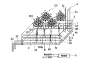
- FIG. 1 is a perspective view which shows one structural example of the hydroponic cultivation apparatus shown as embodiment of this invention.
- FIG. 2 is a perspective view which shows the other structural example of the hydroponic cultivation apparatus shown as embodiment of this invention.
- the hydroponic cultivation apparatus shown as an embodiment of the present invention is configured, for example, as shown in FIG.
- This hydroponic cultivation apparatus does not use soil to grow the plant 100, but supplies a liquid to the main root 102 and the side root 103 (underground) of the plant 100 to cultivate the plant 100. Cultivation is done.
- this hydroponic cultivation apparatus implements both methods of mist cultivation and soy sauce cultivation. If the hydroponic cultivation apparatus shown as this embodiment has the main root part 102 and the side root part 103, the kind of plant body 100 is arbitrary. Moreover, although what supplies a liquid to the plant body 100 is demonstrated in this embodiment, as the said liquid, the culture solution (liquid fertilizer) which added the nutrient to water or water is included.
- the culture solution liquid fertilizer
- the hydroponic cultivation apparatus includes a plant cultivation tank 1, a plant support 2, a main root watering unit 3, a liquid fertilization unit 4, a liquid fertilizer concentration management sensor 5, and a control unit 6.
- the plant cultivation tank 1 has a box-like form, and stores the nutrient solution 10 at the bottom.
- the nutrient solution 10 disposed at the bottom of the plant cultivation tank 1 corresponds to a lateral root irrigation unit.
- the liquid fertilizer sprayed from the mist spray port 3a mentioned later is also mixed with the nutrient solution 10. As shown in FIG. The root of the root fluid part 102, the lateral root part 103, and the fine root extended from the lateral root part 103 are immersed in the nutrient solution 10.
- the nutrient solution 10 is supplied to the plant cultivation tank 1 by a worker or piping or a pump (not shown) into the plant cultivation tank 1.
- the plant cultivation tank 1 functions as a lateral root watering unit that waters the lateral root portion 103 by immersing the lateral root portion 103 in a liquid (the nutrient solution 10).
- a plant support 2 is disposed at the upper end of the plant cultivation tank 1.
- the plant support 2 can be configured by a light shielding sheet or the like that blocks light emitted to the plant 100 from above.
- the plant support 2 is provided with a support 2 a for supporting the plant 100 in a state where the plant 100 is inserted.
- the support 2 a applies pressure from the side of the plant 100 to support the plant 100.
- an annular sponge can be used as the support portion 2a.
- the plant support 2 supports the plant 100 by the frictional force between the sponge and the plant 100.
- any means may be used such as hanging the above-ground part of the plant body 100 with a string-like thing.
- the main root watering unit 3 sprays misty liquid fertilizer (mist) onto the main root portion 102 in the plant cultivation tank 1. As a result, the main root watering unit 3 waters the main root 102.
- the main root irrigation unit 3 has a mist spray port 3a constituted by a plurality of through holes provided in a rod-shaped pipe.
- the main root irrigation unit 3 is connected to a liquid supply pipe (not shown).
- the mist sprayer 3a sprays the liquid supplied from the liquid supply pipe in the form of a mist (mist).
- the mist spraying port 3a may be a nozzle part provided not only in the form shown in FIG. 1, but in each part in the plant cultivation tank 1 and arbitrary height.
- the concentration of the liquid sprayed from the main root irrigation unit 3 may be a predetermined concentration, or may be adjustable by the control unit 6. Moreover, the main root watering unit 3 can adjust the spraying interval at which the mist is sprayed and the spraying time at each spraying interval by the control unit 6.
- the liquid fertilization unit 4 performs fertilization on the nutrient solution 10 in the plant cultivation tank 1.
- the upper part 4 a protrudes from the plant support 2 and the lower part 4 b extends to the plant support 2.
- the liquid fertilization unit 4 is supplied with fertilizer from the upper part 4a and supplies fertilizer to the nutrient solution 10 from the lower part 4b.
- the liquid fertilization unit 4 adjusts the concentration of the nutrient solution 10.
- the liquid fertilization unit 4 performs fertilization, for example, in accordance with a control signal transmitted from the control unit 6.
- the liquid fertilization unit 4 may perform the fertilizing of a predetermined amount at a predetermined time.
- the liquid fertilizer concentration management sensor 5 functions as a detection unit that detects the concentration of the component corresponding to the fertilizer contained in the nutrient solution 10.
- the concentration of the nutrient solution 10 detected by the liquid fertilizer concentration management sensor 5 is read by the control unit 6.
- the control part 6 inputs a sensor signal, outputs a control signal, and controls each part of a plant growing apparatus.
- the control part 6 controls the water
- the control unit 6 controls at least one of the concentration of the liquid sprayed by the mist spray port 3a and the concentration of the nutrient solution 10 in which the lateral root portion 103 is immersed, based on the concentration of the nutrient solution 10. .
- the control unit 6 makes the concentration of the liquid fertilizer sprayed by the main root watering unit 3 different from the concentration of the nutrient solution 10 in which the lateral root portion 103 is immersed.
- the control unit 6 is configured to allow the side root portion 103 to be immersed so as to lower the concentration of the root fluid nutrient solution 10 to which the side root portion 103 is immersed than the concentration of the liquid sprayed by the mist spray port 3a. Control the concentration of solution 10.
- low concentration liquid fertilizer (EC: 1.0 mS / cm or less) is sprayed onto the main root 102 from the mist spray port 3a.
- the control unit 6 immerses the tip of the main root portion 102 and the side root portion 103 using liquid fertilizer (EC: 1.3 mS / cm or more) with a high concentration in the nutrient solution 10.
- control unit 6 in the present embodiment controls the liquid fertilization unit 4 so that the liquid fertilization unit 4 performs additional fertilization on the nourishing solution 10.
- the control unit 6 may not only control the liquid fertilization unit 4 but also control the concentration of liquid fertilizer to be sprayed from the main root watering unit 3.
- the main root 102 and the side root 103 and the main root 102 are enlarged in order to enlarge and grow the main root 102 of the plant 100 having the main root 102 and the side root 103. It can be watered by liquid fertilizer with different concentration. Therefore, according to this hydroponic cultivation apparatus, when growing the plant body 100 simultaneously using two or more types of liquid manure of mist cultivation and soy sauce cultivation, interference of liquid manure concentration can be suppressed.
- the hydroponic cultivation apparatus can control the enlargement and the enlargement direction of the roots of the plant body 100. Furthermore, the hydroponic cultivation apparatus can extend the roots of the plant 100 in the vertical direction. In particular, in the plant 100 having commercial value in the roots, the value can be increased by controlling the enlargement and enlargement directions of the roots. At the same time, by using the main root watering unit 3, it is possible to suppress dryness and rot in root cultivation.
- the concentration of the liquid fertilizer sprayed by the main root watering unit 3 is lower than the concentration of the nutrient solution 10 in which the lateral root portion 103 is immersed.
- the hydroponic cultivation apparatus in this embodiment includes, in addition to the hydroponic cultivation apparatus described above, a separation unit 21, a mist nutrient solution collecting pipe 22, and a nutrient solution collecting pipe 23.
- the separation unit 21 is provided above the nutrient solution 10 in the plant cultivation tank 1.
- the separation unit 21 is arranged to physically separate at least a part of the upper main root watering unit 3 in the plant cultivation tank 1 and the lower side root watering unit in the plant cultivation tank 1.
- the separation unit 21 forms a recovery layer 31 for recovering the liquid sprayed by the mist spray port 3a.
- the lower part of the heavy recovery layer 31 is the immersion layer 32 in which the nutrient solution 10 is present.
- Holes 21 a are provided in the separation part 21 in the extending direction of the plant body 100. Thereby, when the tip of the main root portion 102 and the lateral root portion 103 grow, they can be immersed in the nutrient solution 10.
- the main root irrigation units 3A and 3B are configured by providing piping at a plurality of locations along the wall surface of the plant cultivation tank 1.
- a plurality of spray ports are disposed in the recovery layer 31 so that the height direction in the plant 100 is different.
- the mist nutrient solution collecting pipe 22 is connected to the collecting layer 31 in the plant cultivation tank 1 formed by the separating unit 21.
- the mist nutrient solution recovery pipe 22 recovers the liquid sprayed by the main root watering unit 3 in the recovery layer 31.
- the recovered liquid is regenerated to be a liquid fertilizer or a nutrient solution 10 to be sprayed.
- the mist nutrient solution recovery pipe 22 functions as a recovery and regeneration unit that regenerates the liquid sprayed from the mist spray port 3 a and the nutrient solution 10.
- the nutrient solution recovery pipe 23 is connected below the recovery layer 31 in which the nutrient solution 10 is stored in the plant cultivation tank 1.
- the nutrient solution recovery pipe 23 recovers the nutrient solution 10.
- the mist nutrient solution recovery pipe 22 recovers the nutrient solution 10 fed to the plant cultivation tank 1 by, for example, piping and a pump (not shown).
- the control unit 6 controls the concentration of the liquid sprayed from the mist spray port 3a to be lower than the concentration of the nutrient solution 10 in which the main root portion 102 is immersed. At this time, the control unit 6 controls the concentration of the component corresponding to the fertilizer in the nutrient solution 10. Thereby, the control unit 6 controls the enlargement and the enlargement direction of the roots of the plant body 100.
- high concentration liquid fertilizer (EC: 1.3 mS / cm or more) is sprayed from the main root watering unit 3A.
- a medium concentration liquid fertilizer (EC: 1.0 to 1.3 mS / cm) is sprayed from the main root watering unit 3B.
- high concentration liquid fertilizer and medium concentration liquid fertilizer are sprayed to the fine roots extending from the main root 102 and the main root 102 by the main root irrigation unit 3A and the main root irrigation unit 3B.
- low concentration liquid fertilizer (EC: 1.0 mS / cm or less) is used as the nourishing solution 10.
- the control unit 6 controls the liquid fertilization unit 4 to adjust the concentration of the nutrient solution 10 as in the embodiment described above.
- the hydroponic cultivation apparatus may be capable of controlling either the concentration of the nutrient solution 10 or the concentration sprayed from the main root watering unit 3.
- the separation unit 21 forms a recovery layer 31 for recovering the liquid fertilizer sprayed by the main root irrigation unit 3.
- liquid fertilizer sprayed from the mist spray port 3a can be separated and collected, and liquid fertilizers of different concentrations can be recycled and circulated to grow the plant body 100.
- the concentration of the liquid sprayed by the mist spray port 3a is made higher than the concentration of the nutrient solution 10 in which the side root portion 103 is immersed. At this time, at least one of the concentration of the liquid sprayed by the main root irrigation unit 3 and the concentration of the liquid in which the lateral roots are immersed in the lateral root irrigation unit is controlled. Thereby, according to the hydroponic cultivation apparatus, the root of the plant 100 can be extended in the horizontal direction.
- the collection layer 31 is provided with a plurality of mist spray ports 3 a having different height directions in the plant 100.
- a hydroponic cultivation apparatus sprays liquid manure with a high density
- the root of the plant 100 can be further extended in the horizontal direction.
- ADVANTAGE OF THE INVENTION According to this invention, it can suppress that the liquid manure for mist culture and the liquid manure for soybean juice culture interfere.
- Plant cultivation tank (side root irrigation section) 2 Plant support (support part) 2a Support part 3 Main root irrigation part 3a Mist spray port 4 Liquid fertilization part (control part) 5 Liquid fertilizer concentration management sensor (detection unit) 6 Control part 10 Nose solution nourishing solution (lateral root irrigation part) 21 separation part 22 mist nutrient solution recovery pipe 23 nutrient solution recovery pipe 31 recovery layer
Abstract
Description
2 植物支持体(支持部)
2a 支持部
3 主根潅水部
3a ミスト噴霧口
4 液肥追肥部(制御部)
5 液肥濃度管理センサ(検出部)
6 制御部
10 湛液養液(側根潅水部)
21 分離部
22 ミスト養液回収管
23 湛液養液回収管
31 回収層
Claims (6)
- 主根と側根とを有する植物体を育成する水耕栽培装置であって、
前記植物体を支持する支持部と、
前記主根に霧状に液体を噴霧することにより前記主根への潅水を行う主根潅水部と、
前記側根を液体に浸すことにより前記側根への潅水を行う側根潅水部と、
前記側根潅水部に設けた液体の濃度を検出する検出部とを備え、
前記検出部により検出された濃度を参照し、前記主根潅水部により噴霧される液体の濃度と前記側根潅水部にて前記側根が浸されている液体の濃度との少なくとも一方を制御して、前記主根潅水部により噴霧される液体の濃度と前記側根潅水部にて前記側根が浸されている液体の濃度とを異なるようにする制御部と
を備えることを特徴とする水耕栽培装置。 - 前記制御部は、前記主根潅水部により噴霧される液体の濃度が前記側根潅水部にて前記側根が浸されている液体の濃度よりも低くなるように、前記主根潅水部により噴霧される液体の濃度と前記側根潅水部にて前記側根が浸されている液体の濃度との少なくとも一方を制御することを特徴とする請求項1に記載の水耕栽培装置。
- 前記主根潅水部と前記側根潅水部との少なくとも一部を物理的に分離して、前記主根潅水部により噴霧された液体を回収する回収層を形成する分離部と、
前記回収層における前記主根潅水部により噴霧された液体を回収して、前記主根潅水部により噴霧される液体として再生する回収再生部と
を備えることを特徴とする請求項1に記載の水耕栽培装置。 - 前記制御部は、前記主根潅水部により噴霧される液体の濃度が前記側根潅水部にて前記側根が浸されている液体の濃度よりも高くなるように、前記主根潅水部により噴霧される液体の濃度と前記側根潅水部にて前記側根が浸されている液体の濃度との少なくとも一方を制御することを特徴とする請求項3に記載の水耕栽培装置。
- 前記主根潅水部は、前記回収層に、前記植物体における高さ方向が異なる複数の噴霧口を備え、前記植物体における高さ方向が高いほど濃度の高い液体を噴霧することを特徴とする請求項4に記載の水耕栽培装置。
- 主根と側根とを有する植物体を育成する水耕栽培方法であって、
前記主根への潅水を霧状の液体を噴霧することにより行うと共に、前記側根への潅水を当該側根を液体に浸すことにより行い、
前記側根に潅水している液体の濃度を検出し、
検出した濃度を参照し、前記主根に噴霧される液体の濃度と前記側根が浸されている液体の濃度との少なくとも一方を制御すること
を特徴とする水耕栽培方法。
Priority Applications (4)
| Application Number | Priority Date | Filing Date | Title |
|---|---|---|---|
| CN201480017050.9A CN105050386B (zh) | 2013-04-25 | 2014-03-20 | 水耕栽培装置以及水耕栽培方法 |
| KR1020157026750A KR20150123304A (ko) | 2013-04-25 | 2014-03-20 | 수경 재배 장치 및 수경 재배 방법 |
| EP14788316.9A EP2989888A4 (en) | 2013-04-25 | 2014-03-20 | DEVICE AND METHOD FOR HYDROCULTURES |
| US14/779,434 US20160037738A1 (en) | 2013-04-25 | 2014-03-20 | Hydroponic apparatus and hydroponic method |
Applications Claiming Priority (2)
| Application Number | Priority Date | Filing Date | Title |
|---|---|---|---|
| JP2013092279A JP5662513B2 (ja) | 2013-04-25 | 2013-04-25 | 水耕栽培装置及び水耕栽培方法 |
| JP2013-092279 | 2013-04-25 |
Publications (1)
| Publication Number | Publication Date |
|---|---|
| WO2014174758A1 true WO2014174758A1 (ja) | 2014-10-30 |
Family
ID=51791348
Family Applications (1)
| Application Number | Title | Priority Date | Filing Date |
|---|---|---|---|
| PCT/JP2014/001630 WO2014174758A1 (ja) | 2013-04-25 | 2014-03-20 | 水耕栽培装置及び水耕栽培方法 |
Country Status (6)
| Country | Link |
|---|---|
| US (1) | US20160037738A1 (ja) |
| EP (1) | EP2989888A4 (ja) |
| JP (1) | JP5662513B2 (ja) |
| KR (1) | KR20150123304A (ja) |
| CN (1) | CN105050386B (ja) |
| WO (1) | WO2014174758A1 (ja) |
Families Citing this family (9)
| Publication number | Priority date | Publication date | Assignee | Title |
|---|---|---|---|---|
| FI20110247A0 (fi) | 2011-07-22 | 2011-07-22 | Niko Rainer Jaervinen | Kasvipohjainen biosuodatin ilmapohjaisten haihtuvien orgaanisten yhdisteiden ja mikrobien poistamiseen |
| JP6332696B2 (ja) * | 2015-01-28 | 2018-05-30 | 有限会社 グリーン・グリーン | にんにくの栽培方法 |
| US11089740B2 (en) | 2015-05-26 | 2021-08-17 | Delos Living Llc | Green wall modular system |
| US10781123B2 (en) * | 2017-08-07 | 2020-09-22 | NuLeaf Tech, Inc. | Multi-stage wastewater treatment and hydroponic farming device |
| KR101951702B1 (ko) * | 2017-12-14 | 2019-05-20 | 현대로오텍(주) | 외기와 실내 온도차를 이용한 비닐하우스의 자동온도제어 시스템 |
| US20200170205A1 (en) * | 2018-12-02 | 2020-06-04 | Itay Tayas Zamir | Indoor Plant Growing System |
| US11202417B2 (en) | 2019-12-11 | 2021-12-21 | Herbert Newsam | Modular commercial plant cloning system |
| CN112997872B (zh) * | 2021-02-26 | 2023-01-24 | 爱盛生物科技(上海)有限公司 | 多功能室内植物种植系统 |
| CN114766125B (zh) * | 2022-05-20 | 2023-04-25 | 安徽省农业科学院土壤肥料研究所 | 一种适宜于无人机播种的种子丸粒化制作方法 |
Citations (5)
| Publication number | Priority date | Publication date | Assignee | Title |
|---|---|---|---|---|
| JPS62269632A (ja) * | 1986-05-15 | 1987-11-24 | 岡谷酸素株式会社 | 噴霧式植物栽培装置 |
| JPH0166854U (ja) * | 1987-10-23 | 1989-04-28 | ||
| JPH0546260U (ja) * | 1991-11-29 | 1993-06-22 | カネコ種苗株式会社 | 植物栽培装置 |
| JP2007195514A (ja) * | 2006-01-30 | 2007-08-09 | Tottori Univ | 植物の栽培方法及びその栽培装置 |
| JP2012100573A (ja) | 2010-11-09 | 2012-05-31 | Kajima Corp | 養液栽培システム及び養液栽培方法 |
Family Cites Families (24)
| Publication number | Priority date | Publication date | Assignee | Title |
|---|---|---|---|---|
| US2189510A (en) * | 1938-06-16 | 1940-02-06 | Ellis Lab Inc | Hydroculture plant box |
| SE331610B (ja) * | 1965-10-01 | 1971-01-04 | Wallco Ab | |
| US3660933A (en) * | 1970-03-02 | 1972-05-09 | Weingarten & Wong Enterprises | Hydroponics system and method |
| US3868787A (en) * | 1971-12-29 | 1975-03-04 | Weingarten & Wong Enterprises | Apparatus for supporting hydroponically grown plants |
| US3925926A (en) * | 1973-11-08 | 1975-12-16 | Kyowa Kagaku Kogyo Kk | Method and apparatus for water and air culture of plants |
| US4059922A (en) * | 1976-01-12 | 1977-11-29 | Digiacinto Joseph A | Sprayer hydroponic grower |
| US4178716A (en) * | 1977-01-15 | 1979-12-18 | Fisons Limited | Nutrient film technique |
| US4245433A (en) * | 1979-06-12 | 1981-01-20 | Sjostedt Ernst H S | Method and apparatus of growing plants without soil |
| US4294037A (en) * | 1980-02-13 | 1981-10-13 | National Research Development Corporation | Production of mycorrhizal fungi |
| DK40881A (da) * | 1981-01-30 | 1982-07-31 | Gartnerens Vandings Ind | Vandkulturanlaeg |
| BE1000564A3 (fr) * | 1987-05-18 | 1989-02-07 | Hiveral Sa | Perfectionnement des installations et procedes d'injection de solution nutritive aqueuse dans les cultures hydroponiques. |
| CA1332000C (en) * | 1988-10-04 | 1994-09-13 | Nicola Liburdi | Computerized fertilizer injector system |
| US4992942A (en) * | 1989-01-25 | 1991-02-12 | Bahm, Inc. | Apparatus and method for controlling a system, such as nutrient control system for feeding plants, based on actual and projected data and according to predefined rules |
| JP2592969B2 (ja) * | 1989-12-12 | 1997-03-19 | 株式会社東芝 | 養液制御装置 |
| DE69113436T2 (de) * | 1991-01-30 | 1996-03-07 | Erma Cr Inc | Hydrokultursystem. |
| BE1005439A3 (fr) * | 1991-10-09 | 1993-07-27 | Julien Philippe | Dispositif d'injection des solutions nutritives pour cultures aero-hydroponiques. |
| JP3505046B2 (ja) * | 1996-09-30 | 2004-03-08 | 日本たばこ産業株式会社 | バレイショ塊茎生産方法 |
| CN2389465Y (zh) * | 1999-09-23 | 2000-08-02 | 李明 | 无土栽培营养液浓度自动调整装置 |
| US20060179711A1 (en) * | 2003-11-17 | 2006-08-17 | Aerogrow International, Inc. | Devices and methods for growing plants |
| US8904705B2 (en) * | 2010-07-07 | 2014-12-09 | Thomas J. Downs, SR. | Aeroponic system and sprayer device for improved plant growth and aeration |
| US8448379B2 (en) * | 2010-12-09 | 2013-05-28 | Larry Y Igarashi | Pure-grown totally concealed clean room vegetable factory |
| US8621781B2 (en) * | 2011-09-27 | 2014-01-07 | Vijay Singh | Hydroponic irrigation system |
| JP6331248B2 (ja) * | 2012-01-16 | 2018-05-30 | パナソニックIpマネジメント株式会社 | 植物育成装置 |
| US9433160B2 (en) * | 2013-03-21 | 2016-09-06 | Disney Enterprises, Inc. | Hydroponic array for the individualized delivery of nutrients |
-
2013
- 2013-04-25 JP JP2013092279A patent/JP5662513B2/ja not_active Expired - Fee Related
-
2014
- 2014-03-20 WO PCT/JP2014/001630 patent/WO2014174758A1/ja active Application Filing
- 2014-03-20 KR KR1020157026750A patent/KR20150123304A/ko not_active Application Discontinuation
- 2014-03-20 CN CN201480017050.9A patent/CN105050386B/zh not_active Expired - Fee Related
- 2014-03-20 US US14/779,434 patent/US20160037738A1/en not_active Abandoned
- 2014-03-20 EP EP14788316.9A patent/EP2989888A4/en not_active Withdrawn
Patent Citations (5)
| Publication number | Priority date | Publication date | Assignee | Title |
|---|---|---|---|---|
| JPS62269632A (ja) * | 1986-05-15 | 1987-11-24 | 岡谷酸素株式会社 | 噴霧式植物栽培装置 |
| JPH0166854U (ja) * | 1987-10-23 | 1989-04-28 | ||
| JPH0546260U (ja) * | 1991-11-29 | 1993-06-22 | カネコ種苗株式会社 | 植物栽培装置 |
| JP2007195514A (ja) * | 2006-01-30 | 2007-08-09 | Tottori Univ | 植物の栽培方法及びその栽培装置 |
| JP2012100573A (ja) | 2010-11-09 | 2012-05-31 | Kajima Corp | 養液栽培システム及び養液栽培方法 |
Non-Patent Citations (1)
| Title |
|---|
| See also references of EP2989888A4 |
Also Published As
| Publication number | Publication date |
|---|---|
| CN105050386B (zh) | 2017-04-26 |
| EP2989888A1 (en) | 2016-03-02 |
| EP2989888A4 (en) | 2016-04-27 |
| JP5662513B2 (ja) | 2015-01-28 |
| US20160037738A1 (en) | 2016-02-11 |
| CN105050386A (zh) | 2015-11-11 |
| KR20150123304A (ko) | 2015-11-03 |
| JP2014212725A (ja) | 2014-11-17 |
Similar Documents
| Publication | Publication Date | Title |
|---|---|---|
| WO2014174758A1 (ja) | 水耕栽培装置及び水耕栽培方法 | |
| CA2660284A1 (en) | Plant cultivation system | |
| JP2016518120A (ja) | 垂直ガーデンシステム | |
| Pradhan et al. | Soilless farming–the next generation green revolution | |
| JP2006320296A (ja) | チャの育苗方法 | |
| US20180338430A1 (en) | Aeroponic irrigation system | |
| CN206547527U (zh) | 一种林木智能化养护系统 | |
| US20180206421A1 (en) | Segregated hydroponic assembly | |
| AU2011285753A1 (en) | Irrigation system and method | |
| JP2012217373A (ja) | 養液栽培の培地 | |
| JP4759734B2 (ja) | 水耕栽培装置 | |
| KR102320847B1 (ko) | 분무식 수경 재배장치 | |
| CN203814327U (zh) | 无土栽培盆 | |
| CN105493945B (zh) | 秧苗的培育装置 | |
| KR101650690B1 (ko) | 요철이 형성된 화분 수직 재배장치 | |
| CN204409165U (zh) | 无土栽培装置 | |
| CN203105263U (zh) | 一种立体栽培装置 | |
| CN204811231U (zh) | 一种节省土地的农业移动种植装置 | |
| CN204047332U (zh) | 一种立柱式栽培装置 | |
| CN202819208U (zh) | 一种柱式栽培架 | |
| KR100463429B1 (ko) | 영양액 분무식 수경재배장치 | |
| CN104041400A (zh) | 新型无土栽培种植袋及新型无土栽培种植系统 | |
| CN212753479U (zh) | 一种多功能育苗容器架 | |
| KR102342010B1 (ko) | 벽천형 수경식생시스템 | |
| KR20110020956A (ko) | 지중배관으로 식물성장에 필요한 물품을 공급하고 방해물을 배출하는 식물재배 방법과 그 장치 |
Legal Events
| Date | Code | Title | Description |
|---|---|---|---|
| WWE | Wipo information: entry into national phase |
Ref document number: 201480017050.9 Country of ref document: CN |
|
| 121 | Ep: the epo has been informed by wipo that ep was designated in this application |
Ref document number: 14788316 Country of ref document: EP Kind code of ref document: A1 |
|
| WWE | Wipo information: entry into national phase |
Ref document number: 14779434 Country of ref document: US |
|
| ENP | Entry into the national phase |
Ref document number: 20157026750 Country of ref document: KR Kind code of ref document: A |
|
| REEP | Request for entry into the european phase |
Ref document number: 2014788316 Country of ref document: EP |
|
| WWE | Wipo information: entry into national phase |
Ref document number: 2014788316 Country of ref document: EP |
|
| NENP | Non-entry into the national phase |
Ref country code: DE |