WO2014168258A1 - 光学異方性フィルムの製造方法 - Google Patents
光学異方性フィルムの製造方法 Download PDFInfo
- Publication number
- WO2014168258A1 WO2014168258A1 PCT/JP2014/060884 JP2014060884W WO2014168258A1 WO 2014168258 A1 WO2014168258 A1 WO 2014168258A1 JP 2014060884 W JP2014060884 W JP 2014060884W WO 2014168258 A1 WO2014168258 A1 WO 2014168258A1
- Authority
- WO
- WIPO (PCT)
- Prior art keywords
- optically anisotropic
- liquid crystal
- film
- anisotropic film
- crystal compound
- Prior art date
- Legal status (The legal status is an assumption and is not a legal conclusion. Google has not performed a legal analysis and makes no representation as to the accuracy of the status listed.)
- Ceased
Links
- 0 CCOC(CC1)CCC1C(OC(CC1)CC2C1C(CC[C@](C1)OC(C3CCC([*+])CC3)=O)C1C2C)=O Chemical compound CCOC(CC1)CCC1C(OC(CC1)CC2C1C(CC[C@](C1)OC(C3CCC([*+])CC3)=O)C1C2C)=O 0.000 description 1
Images


Classifications
-
- G—PHYSICS
- G02—OPTICS
- G02B—OPTICAL ELEMENTS, SYSTEMS OR APPARATUS
- G02B5/00—Optical elements other than lenses
- G02B5/30—Polarising elements
- G02B5/3016—Polarising elements involving passive liquid crystal elements
Definitions
- the present invention relates to a method for producing an optically anisotropic film.
- an optically anisotropic film such as a polarizing plate and a retardation plate are used.
- an optically anisotropic film an optically anisotropic film produced by applying a composition containing a polymerizable liquid crystal compound to a substrate is known.
- a coating film is obtained by applying a composition containing a polymerizable liquid crystal compound to an alignment-treated substrate, and the polymerizable liquid crystal compound is polymerized by irradiating the coating film with light.
- the manufacturing method of the optically anisotropic film to be made is described, it is not described about the conditions at the time of irradiating light.
- the present invention includes the following inventions.
- a method for producing an optically anisotropic film including the following steps (1) and (2): (1) Step of applying an optical anisotropic layer forming composition containing a polymerizable liquid crystal compound and a photopolymerization initiator on the surface of the alignment film (2) Applying the applied optical anisotropic layer forming composition to an oxygen concentration A process of irradiating the composition for forming an optically anisotropic layer with light while maintaining the liquid crystal-liquid phase transition temperature or lower of the polymerizable liquid crystal compound in an atmosphere of 0.5% or less [2] In the process (2) The method for producing an optically anisotropic film according to [1], wherein the temperature for holding the applied composition for forming an optically anisotropic layer is 80 ° C.
- Step of applying an optical anisotropic layer forming composition containing a polymerizable liquid crystal compound and a photopolymerization initiator on the surface of the alignment film (2) Applying the applied optical anisotropic layer forming composition to an oxygen concentration
- Vertically aligned polymerizability The optically anisotropic film according to [10], which is formed from a liquid crystal compound.
- a front retardation value Re (549) is 0 ⁇ 10 nm
- optically anisotropic film according to the phase difference value in the thickness direction R th is -10 ⁇ -300 nm [10] or [11].
- the polarizing plate according to [14], wherein the degree of polarization is 99.97% or more.
- a display device comprising the optically anisotropic film according to any one of [10] to [13].
- an optically anisotropic film excellent in transparency and durability of optical anisotropy can be produced.
- the method for producing an optically anisotropic film of the present invention includes the following steps (1) and (2).
- the alignment film is usually formed on the substrate surface.
- a transparent substrate is usually used.
- a transparent substrate means a substrate having translucency capable of transmitting light, particularly visible light, and the translucency is a transmittance with respect to a light beam having a wavelength of 380 to 780 nm of 80% or more.
- Specific examples of the transparent substrate include glass and a translucent resin substrate, and a translucent resin substrate is preferable.
- a film is usually used, and a roll film is preferably used.
- Polyethylene such as polyethylene, polypropylene and norbornene polymers; polyvinyl alcohol; polyethylene terephthalate; polymethacrylic acid ester; polyacrylic acid ester; cellulose ester; polyethylene naphthalate; polycarbonate; polysulfone; And sulfone; polyether ketone; polyphenylene sulfide; and polyphenylene oxide.
- a substrate made of polyolefin such as polyethylene, polypropylene, norbornene-based polymer is preferable.
- the substrate may be surface treated.
- the surface treatment include a method of treating the surface of the substrate with corona or plasma under vacuum or atmospheric pressure, a method of laser treating the surface of the substrate, a method of treating the surface of the substrate with ozone, and a surface of the substrate.
- Saponification method or flame treatment of substrate surface, method of applying coupling agent to substrate surface, method of primer treatment, reactive monomer or reactive polymer adhered to substrate surface Thereafter, a graft polymerization method in which the reaction is performed by irradiation with radiation, plasma, or ultraviolet rays may be mentioned.
- a method of corona or plasma treatment of the substrate surface under vacuum or atmospheric pressure is preferable.
- a method of performing surface treatment of a substrate with corona or plasma a method of performing surface treatment of the substrate by installing a substrate between opposed electrodes and generating corona or plasma under a pressure near atmospheric pressure.
- the surface treatment of a substrate by flowing a gas between opposed electrodes, converting the gas into a plasma between the electrodes, and blowing the plasmaized gas onto the substrate, and generating glow discharge plasma under low pressure conditions.
- a substrate is placed between opposed electrodes, and corona or plasma is generated to treat the surface of the substrate, or a gas is flowed between the opposed electrodes.
- a method is preferred in which the gas is converted into plasma and the plasmaized gas is sprayed onto the substrate.
- Such surface treatment with corona or plasma is usually performed by a commercially available surface treatment apparatus.
- the alignment film in the present specification does not dissolve in the composition for forming an optical anisotropic layer, but is heated by adjusting the liquid crystal alignment of the polymerizable liquid crystal compound by removing the solvent contained in the composition for forming the optical anisotropic layer. Those that do not change in quality and do not peel off due to friction during film conveyance are preferred.
- a method of forming the alignment film a method of applying and drying the alignment polymer on the surface of the substrate, a method of applying and drying the alignment polymer and rubbing the surface, a method of applying the photo-alignment polymer, drying and polarizing Examples thereof include a method of irradiation, a method of obliquely depositing silicon oxide, and a method of forming a monomolecular film having a long-chain alkyl group using the Langmuir-Blodgett method (LB method).
- the alignment polymer and the photo-alignment polymer are usually applied after being dissolved in a solvent.
- alignment polymer examples include polyamides and gelatins having an amide bond in the molecule, polyimides having an imide bond in the molecule and polyamic acid, polyvinyl alcohol, alkyl-modified polyvinyl alcohol, polyacrylamide, polyoxazole, Examples include polyethyleneimine, polystyrene, polyvinylpyrrolidone, polyacrylic acid, and polyacrylic acid esters. Among these, polyamide, polyimide, or polyamic acid is preferable.
- the alignment polymer forming the alignment film may be one type, a composition combining a plurality of types of polymers, or a copolymer combining a plurality of types of polymers.
- polymers can be easily obtained by subjecting the monomer to polycondensation such as dehydration or dealcoholization, chain polymerization such as radical polymerization, anionic polymerization, and cationic polymerization, coordination polymerization, or ring-opening polymerization.
- orientation polymers include Sanever (registered trademark, manufactured by Nissan Chemical Industries), Optomer (registered trademark, manufactured by JSR), and the like.
- An alignment film formed from such an alignment polymer facilitates liquid crystal alignment of the polymerizable liquid crystal compound.
- various liquid crystal alignments such as horizontal alignment, vertical alignment, hybrid alignment, and tilt alignment can be controlled depending on the type of alignment polymer and rubbing conditions, and can be used to improve the viewing angle of various liquid crystal panels.
- Examples of the photo-alignment polymer include a polymer having a photosensitive structure.
- a polymer having a photosensitive structure When a polymer having a photosensitive structure is irradiated with polarized light, the photosensitive structure in the irradiated portion is isomerized or cross-linked so that the photo-alignable polymer is aligned, and an alignment regulating force is imparted to the film made of the photo-alignable polymer.
- the Examples of the photosensitive structure include an azobenzene structure, a maleimide structure, a chalcone structure, a cinnamic acid structure, a 1,2-vinylene structure, a 1,2-acetylene structure, a spiropyran structure, a spirobenzopyran structure, and a fulgide structure.
- the photo-alignment polymer that forms the alignment film may be one type, a combination of a plurality of polymers having different structures, or a copolymer having a plurality of different photosensitive structures.
- the photoalignable polymer is obtained by subjecting a monomer having a photosensitive structure to polycondensation such as dehydration or dealcoholization, chain polymerization such as radical polymerization, anion polymerization, or cationic polymerization, coordination polymerization, or ring-opening polymerization.
- Examples of the photo-alignment polymer include light described in Japanese Patent No. 4450261, Japanese Patent No. 4011652, Japanese Patent Application Laid-Open No. 2010-49230, Japanese Patent No. 444090, Japanese Patent Application Publication No. 2007-156439, Japanese Patent Application Laid-Open No. 2007-232934, and the like.
- An orientation polymer etc. are mentioned.
- the photo-alignment polymer a polymer that forms a crosslinked structure by irradiation with polarized light is preferable from the viewpoint of durability.
- the method of applying and drying the alignment polymer, and the application of the alignment polymer A method of drying and rubbing the surface is preferred.
- Examples of the solvent that dissolves the alignment polymer or photoalignment polymer include water; alcohol solvents such as methanol, ethanol, ethylene glycol, isopropyl alcohol, propylene glycol, methyl cellosolve, and butyl cellosolve; ethyl acetate, butyl acetate, and ethylene glycol methyl.
- alcohol solvents such as methanol, ethanol, ethylene glycol, isopropyl alcohol, propylene glycol, methyl cellosolve, and butyl cellosolve
- ethyl acetate, butyl acetate, and ethylene glycol methyl examples of the solvent that dissolves the alignment polymer or photoalignment polymer.
- Ester solvents such as ether acetate, ⁇ -butyrolactone, propylene glycol methyl ether acetate, ethyl lactate; ketone solvents such as acetone, methyl ethyl ketone, cyclopentanone, cyclohexanone, methyl amyl ketone, methyl isobutyl ketone, N-methyl-2-pyrrolidone; Aliphatic hydrocarbon solvents such as pentane, hexane, heptane and ethylcyclohexane; aromatic hydrocarbon solvents such as toluene, xylene and chlorobenzene; Nitrile solvents such as nitriles; propylene glycol monomethyl ether, tetrahydrofuran, an ether solvent such as dimethoxyethane; halogenated hydrocarbon solvents such as chloroform and the like. These organic solvents may be used alone or in combination.
- the solvent is usually 10 parts by mass to 100000 parts by mass, preferably 1000 parts by mass to 50000 parts by mass, more preferably 2000 parts by mass to 20000 parts by mass with respect to 100 parts by mass of the orientation polymer or photoalignment polymer. Part.
- Examples of the method for dissolving the orientation polymer or the photo-orientation polymer in a solvent and applying the polymer to a substrate include an extrusion coating method, a direct gravure coating method, a reverse gravure coating method, a CAP coating method, and a die coating method.
- coating using coaters such as a dip coater, a bar coater, a spin coater, is also mentioned.
- Drying methods include natural drying, ventilation drying, heat drying, vacuum drying, and a combination of these.
- the drying temperature is preferably 10 to 250 ° C, more preferably 25 to 200 ° C.
- the drying time is preferably 5 seconds to 60 minutes, more preferably 10 seconds to 30 minutes, depending on the type of solvent.
- the rubbing method includes a method in which a rubbing roll is wound and a rotating rubbing roll is brought into contact with an oriented polymer that has been applied to a substrate and dried.
- Examples of the method of irradiating polarized light include a method using an apparatus described in JP-A-2006-323060.
- a patterned alignment film can be formed by repeatedly irradiating polarized light such as linearly polarized ultraviolet light for each region through a photomask corresponding to a desired plurality of regions.
- polarized light such as linearly polarized ultraviolet light
- a photomask usually, a light shielding pattern provided on a film of quartz glass, soda lime glass or polyester is used. The portion covered with the light-shielding pattern blocks the irradiated polarized light, and the portion not covered transmits the irradiated polarized light. Quartz glass is preferable in that the influence of thermal expansion is small.
- the irradiated polarized light is preferably ultraviolet light.
- the thickness of the alignment film is usually 10 nm to 10000 nm, preferably 10 nm to 1000 nm.
- the polymerizable liquid crystal compound can be easily aligned in a desired direction or angle, which is preferable.
- composition for forming an optically anisotropic layer contains a polymerizable liquid crystal compound and a photopolymerization initiator.
- Examples of the polymerizable liquid crystal compound include a compound containing a group represented by the formula (X) (hereinafter sometimes referred to as “compound (X)”).
- compound (X) a compound containing a group represented by the formula (X)
- One type of polymerizable liquid crystal compound may be used, or a plurality of compounds having different structures may be combined.
- P 11 -B 11 -E 11 -B 12 -A 11 -B 13 - (X) [In formula (X), P 11 represents a polymerizable group.
- a 11 represents a divalent alicyclic hydrocarbon group or a divalent aromatic hydrocarbon group.
- the hydrogen atom contained in the divalent alicyclic hydrocarbon group and divalent aromatic hydrocarbon group is a halogen atom, an alkyl group having 1 to 6 carbon atoms, an alkoxy group having 1 to 6 carbon atoms, a cyano group or a nitro group.
- the hydrogen atom contained in the alkyl group having 1 to 6 carbon atoms and the alkoxy group having 1 to 6 carbon atoms may be substituted with a fluorine atom.
- B 11 is —O—, —S—, —CO—O—, —O—CO—, —O—CO—O—, —CO—NR 16 —, —NR 16 —CO—, —CO—, -CS- or a single bond is represented.
- R 16 represents a hydrogen atom or an alkyl group having 1 to 6 carbon atoms.
- E 11 represents an alkanediyl group having 1 to 12 carbon atoms, and a hydrogen atom contained in the alkanediyl group may be substituted with an alkoxy group having 1 to 5 carbon atoms, and hydrogen contained in the alkoxy group The atom may be substituted with a halogen atom.
- —CH 2 — constituting the alkanediyl group may be replaced by —O— or —CO—.
- the carbon number of the divalent aromatic hydrocarbon group and divalent alicyclic hydrocarbon group represented by A 11 is preferably in the range of 3 to 18, more preferably in the range of 5 to 12. It is preferably 5 or 6, and particularly preferably.
- a 11 is preferably a cyclohexane-1,4-diyl group or a 1,4-phenylene group.
- the alkanediyl group having 1 to 12 carbon atoms represented by E 11 is preferably a linear alkanediyl group having 1 to 12 carbon atoms.
- —CH 2 — constituting the alkanediyl group having 1 to 12 carbon atoms may be replaced by —O—.
- methylene group ethylene group, propane-1,3-diyl group, butane-1,4-diyl group, pentane-1,5-diyl group, hexane-1,6-diyl group, heptane-1 , 7-diyl group, octane-1,8-diyl group, nonane-1,9-diyl group, decane-1,10-diyl group, undecane-1,11-diyl group and dodecane-1,12-diyl group
- a linear alkanediyl group having 1 to 12 carbon atoms such as: —CH 2 —CH 2 —O—CH 2 —CH 2 —, —CH 2 —CH 2 —O—CH 2 —CH 2 —O—CH 2; —CH 2 — and —CH 2 —CH 2 —O—CH 2 —CH 2 —O—CH 2 —CH 2 —O—CH
- B 11 is preferably —O—, —S—, —CO—O—, or —O—CO—, and more preferably —CO—O—.
- B 12 and B 13 are each independently —O—, —S—, —C ( ⁇ O) —, —C ( ⁇ O) —O—, —O—C ( ⁇ O) —, —O.
- —C ( ⁇ O) —O— is preferable, and —O— or —O—C ( ⁇ O) —O— is more preferable.
- the polymerizable group represented by P 11 is preferably a radically polymerizable group or a cationically polymerizable group in that it easily undergoes a photopolymerization reaction, and is easy to handle and easy to produce a polymerizable liquid crystal compound itself. Therefore, the polymerizable group is preferably a group represented by the following formula (P-11) to formula (P-15). [In the formulas (P-11) to (P-15), R 17 to R 21 each independently represents an alkyl group having 1 to 6 carbon atoms or a hydrogen atom. ]
- P 11 is preferably a group represented by formula (P-14) to formula (P-20), more preferably a vinyl group, a p-stilbene group, an epoxy group or an oxetanyl group. More preferably, the group represented by P 11 -B 11- is an acryloyloxy group or a methacryloyloxy group.
- Examples of compound (X) include compounds represented by formula (I), formula (II), formula (III), formula (IV), formula (V) or formula (VI).
- P 11 -B 11 -E 11 -B 12 -A 11 -B 13 -A 12 -B 14 -A 13 -B 15 -A 14 -B 16 -E 12 -B 17 -P 12 (I) P 11 -B 11 -E 11 -B 12 -A 11 -B 13 -A 12 -B 14 -A 13 -B 15 -A 14 -F 11 (II) P 11 -B 11 -E 11 -B 12 -A 11 -B 13 -A 12 -B 14 -A 13 -B 15 -E 12 -B 17 -P 12 (III) P 11 -B 11 -E 11 -B 12 -A 11 -B 13 -A 12 -B 14 -A 13 -F 11 (IV) P 11 -B 11 -E 11
- F 11 is a hydrogen atom, an alkyl group having 1 to 13 carbon atoms, an alkoxy group having 1 to 13 carbon atoms, a cyano group, a nitro group, a trifluoromethyl group, a dimethylamino group, a hydroxy group, a methylol group, a formyl group, a sulfo group.
- polymerizable liquid crystal compound examples include “3.8.6 Network (fully cross-linked type)”, “6” of Liquid Crystal Handbook (Edited by Liquid Crystal Handbook Editorial Committee, published by Maruzen Co., Ltd., October 30, 2000). .5.1 Liquid Crystal Material b. Polymerizable Nematic Liquid Crystal Material ”compound having a polymerizable group, JP 2010-31223 A, JP 2010-270108 A, JP 2011-6360 A And polymerizable liquid crystal compounds described in JP-A-2011-207765.
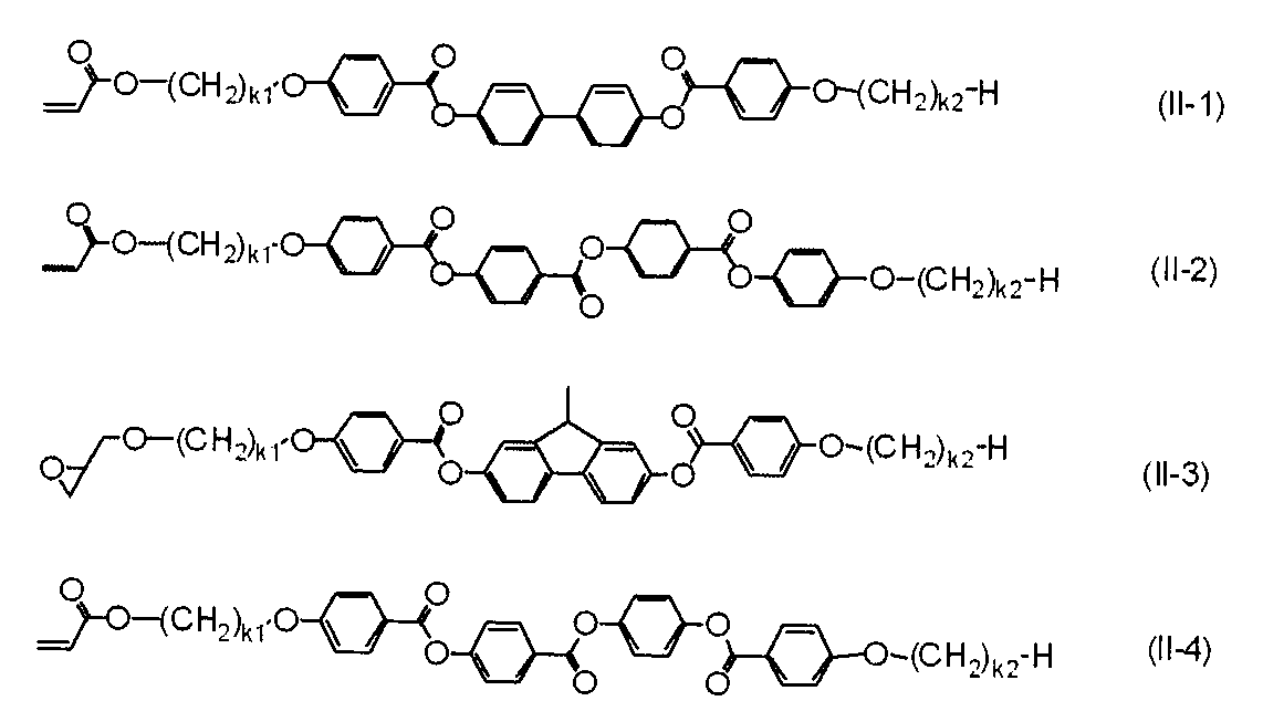
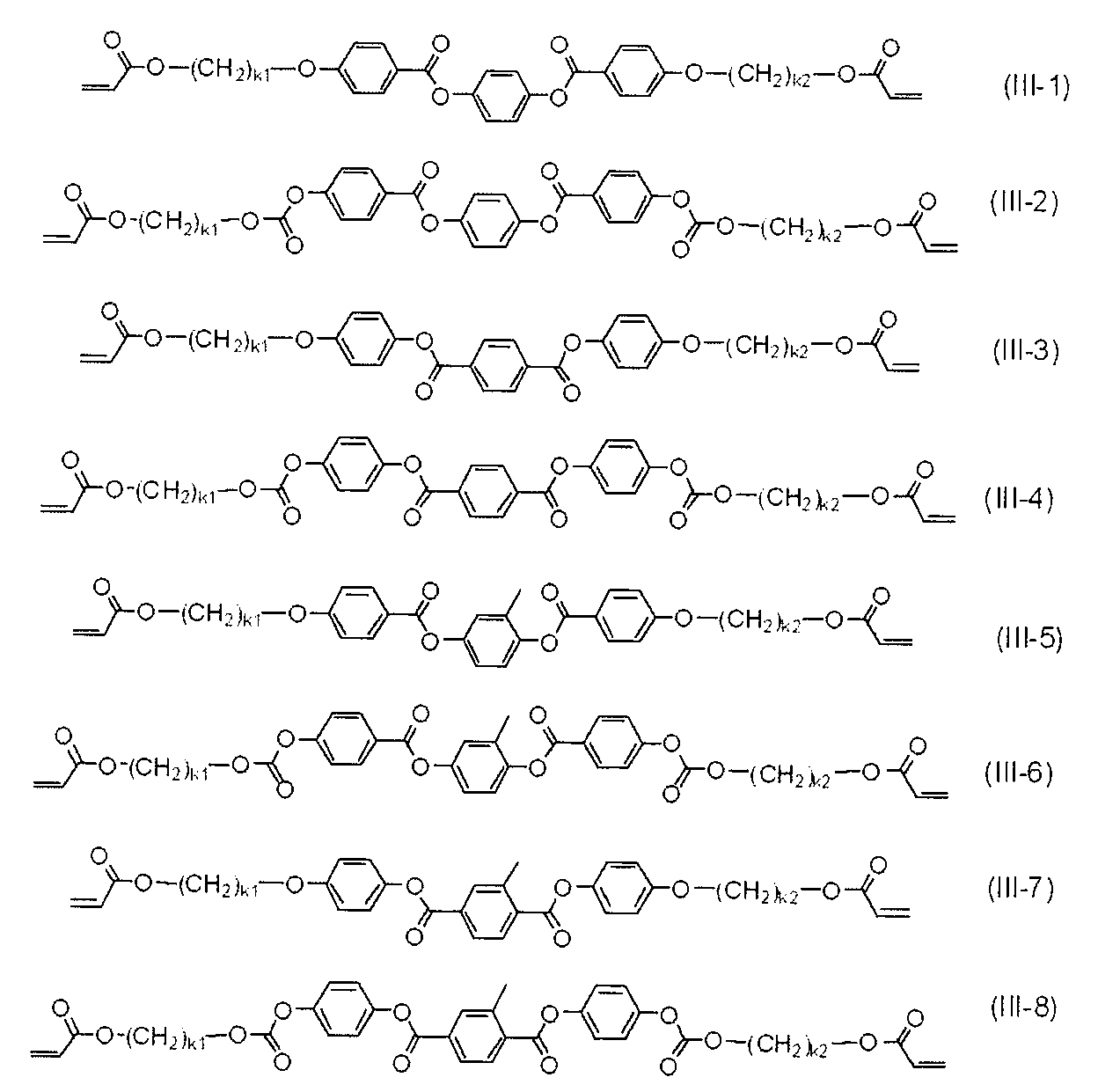
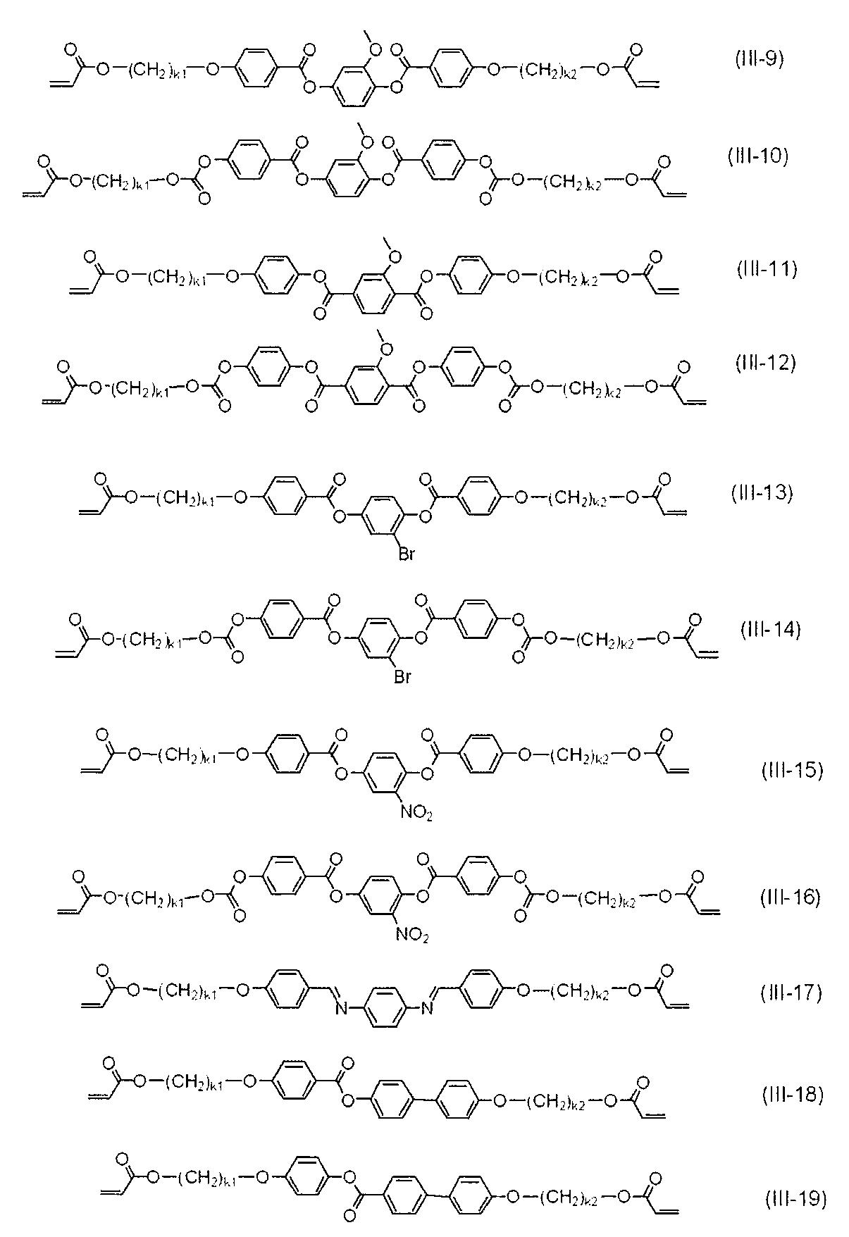
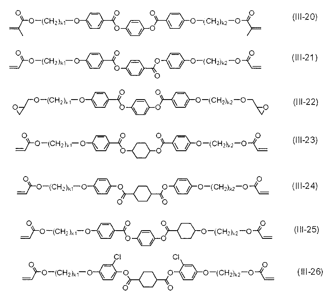
- the compound (X) include the following formula (I-1) to formula (I-4), formula (II-1) to formula (II-4), formula (III-1) to formula (III- 26), compounds represented by formula (IV-1) to formula (IV-26), formula (V-1) to formula (V-2) and formula (VI-1) to formula (VI-6). It is done.
- k1 and k2 each independently represents an integer of 2 to 12.
- the content of the polymerizable liquid crystal compound in the optical anisotropic layer forming composition is usually 5 parts by mass to 50 parts by mass, preferably 10 parts by mass to 100 parts by mass of the optical anisotropic layer forming composition. 30 parts by mass.
- photoinitiator what generate
- the photopolymerization initiator include benzoin compounds, benzophenone compounds, benzyl ketal compounds, ⁇ -hydroxyketone compounds, ⁇ -aminoketone compounds, ⁇ -acetophenone compounds, triazine compounds, iodonium salts, and sulfonium salts.
- Irgacure 907, Irgacure 184, Irgacure 651, Irgacure 819, Irgacure 250, Irgacure 369 (all are made by Ciba Japan Co., Ltd.), Sake All BZ, Sake All Z, Sake All BEE (all are all Seiko) Chemical Co., Ltd.), kayacure BP100 (manufactured by Nippon Kayaku Co., Ltd.), kayakure UVI-6992 (manufactured by Dow), Adekaoptomer SP-152, Adekaoptomer SP-170 (all above, ADEKA Corporation) Product), TAZ-A, TAZ-PP (manufactured by Nippon Siebel Hegner) and TAZ-104 (manufactured by Sanwa Chemical Co., Ltd.).
- ⁇ -acetophenone compounds are preferable, and examples of ⁇ -acetophenone compounds include 2-methyl-2-morpholino-1- (4-methylsulfanylphenyl) propan-1-one, 2-dimethylamino-1- (4-morpholino Phenyl) -2-benzylbutan-1-one, 2-dimethylamino-1- (4-morpholinophenyl) -2- (4-methylphenylmethyl) butan-1-one and the like, more preferably 2- And methyl-2-morpholino-1- (4-methylsulfanylphenyl) propan-1-one and 2-dimethylamino-1- (4-morpholinophenyl) -2-benzylbutan-1-one.
- Examples of commercially available products of ⁇ -acetophenone compounds include Irgacure 369, 379EG, 907 (above, manufactured by BASF Japan Ltd.), Sequol BEE (manufactured by Seiko Chemical Co., Ltd.), and the like.
- the photopolymerization initiator is usually 0.1 to 30 parts by mass, preferably 0.5 to 10 parts by mass with respect to 100 parts by mass of the polymerizable liquid crystal compound. Within the above range, the polymerizable liquid crystal compound can be polymerized without disturbing the liquid crystal alignment of the polymerizable liquid crystal compound.
- composition for forming an optically anisotropic layer may further contain a polymerization inhibitor, a photosensitizer, a leveling agent, a chiral agent, a reactive additive, a solvent and the like.
- Polymerization inhibitor can control the polymerization reaction of the polymerizable liquid crystal compound.
- Polymerization inhibitors include hydroquinones having substituents such as hydroquinone and alkyl ethers; catechols having substituents such as alkyl ethers such as butylcatechol; pyrogallols, 2,2,6,6-tetramethyl-1- Radical scavengers such as piperidinyloxy radicals; thiophenols; ⁇ -naphthylamines and ⁇ -naphthols.
- the content of the polymerization inhibitor in the composition for forming an optically anisotropic layer is usually 0.1 to 30 parts by mass, preferably 0.5 to 10 parts by mass with respect to 100 parts by mass of the polymerizable liquid crystal compound. Part by mass. If it is in the said range, it can superpose
- Examples of the photosensitizer include xanthones such as xanthone and thioxanthone; anthracene having a substituent such as anthracene and alkyl ether; phenothiazine; and rubrene.
- xanthones such as xanthone and thioxanthone
- anthracene having a substituent such as anthracene and alkyl ether
- phenothiazine phenothiazine
- rubrene a photosensitizer
- the content of the photosensitizer is usually 0.1 to 30 parts by mass, preferably 0.5 to 10 parts by mass with respect to 100 parts by mass of the polymerizable liquid crystal compound.
- Leveling agent examples include organic modified silicone oil-based, polyacrylate-based and perfluoroalkyl-based leveling agents. Specifically, DC3PA, SH7PA, DC11PA, SH28PA, SH29PA, SH30PA, ST80PA, ST86PA, SH8400, SH8700, FZ2123 (all are manufactured by Toray Dow Corning Co., Ltd.), KP321, KP323, KP324, KP326, KP340, KP341, X22-161A, KF6001 (all manufactured by Shin-Etsu Chemical Co., Ltd.), TSF400, TSF401, TSF410, TSF4300, TSF4440, TSF4445, TSF-4446, TSF4452, TSF4460 (all, Momentive Performance Materials Japan GK) Manufactured), Fluorinert (registered trademark) FC-72, FC-40, FC-43, FC-3283 (above, Manufactured by Sumitomo 3M Co
- a smoother optically anisotropic film can be formed.
- the fluidity of the composition for forming an optically anisotropic layer can be controlled, and the crosslinking density of the optically anisotropic film can be adjusted.
- the content of the leveling agent is usually 0.1 to 30 parts by mass, preferably 0.1 to 10 parts by mass with respect to 100 parts by mass of the polymerizable liquid crystal compound.
- chiral agent examples include known chiral agents (for example, liquid crystal device handbook, Chapter 3-4-3, TN, chiral agent for STN, 199 pages, edited by Japan Society for the Promotion of Science, 142nd Committee, 1989). It is done.
- the chiral agent generally contains an asymmetric carbon atom, but an axially asymmetric compound or a planar asymmetric compound containing no asymmetric carbon atom can also be used as the chiral agent.
- the axial asymmetric compound or the planar asymmetric compound include binaphthyl, helicene, paracyclophane, and derivatives thereof.
- PALIOCOLOR (registered trademark) LC756 manufactured by BASF Japan Ltd. are preferable.
- the content of the chiral agent is usually 0.1 to 30 parts by mass, preferably 1.0 to 25 parts by mass with respect to 100 parts by mass of the polymerizable liquid crystal compound. If it is in the said range, when superposing
- the reactive additive is preferably one having a carbon-carbon unsaturated bond and an active hydrogen reactive group in the molecule.
- the “active hydrogen reactive group” as used herein is a group reactive to a group having active hydrogen such as a carboxyl group (—COOH), a hydroxyl group (—OH), an amino group (—NH 2 ), and the like. Typical examples include glycidyl group, oxazoline group, carbodiimide group, aziridine group, imide group, isocyanato group, thioisocyanato group, maleic anhydride group and the like.
- the reactive additive it is preferable that at least two active hydrogen reactive groups are present. In this case, a plurality of active hydrogen reactive groups may be the same or different.
- the carbon-carbon unsaturated bond of the reactive additive may be a carbon-carbon double bond, a carbon-carbon triple bond, or a combination thereof, but is preferably a carbon-carbon double bond.
- the reactive additive preferably contains a carbon-carbon unsaturated bond as a vinyl group and / or a (meth) acryl group.
- the active hydrogen reactive group is preferably at least one selected from the group consisting of an epoxy group, a glycidyl group and an isocyanato group, and a reactive additive having an acrylic group and an isocyanato group is particularly preferable.
- reactive additives include compounds having (meth) acrylic groups and epoxy groups, such as methacryloxyglycidyl ether and acryloxyglycidyl ether; (meth) acrylic groups and oxetane, such as oxetane acrylate and oxetane methacrylate.
- a compound having a group a compound having a (meth) acryl group and a lactone group, such as lactone acrylate and lactone methacrylate; a compound having a vinyl group and an oxazoline group, such as vinyl oxazoline and isopropenyl oxazoline; isocyanatomethyl acrylate , Oligomers of compounds having (meth) acrylic groups and isocyanato groups, such as isocyanatomethyl methacrylate, 2-isocyanatoethyl acrylate and 20 isocyanatoethyl methacrylate And the like. Moreover, the compound etc.
- methacryloxyglycidyl ether methacryloxyglycidyl ether, acryloxyglycidyl ether, isocyanatomethyl acrylate, isocyanatomethyl methacrylate, vinyl oxazoline, 2-isocyanatoethyl acrylate, 2-isocyanatoethyl methacrylate and the above oligomers are preferred, isocyanatomethyl acrylate, 2-isocyanatoethyl acrylate and the aforementioned oligomers are particularly preferred.
- This preferable reactive additive is represented by the following formula (Y), for example.
- n represents an integer of 1 to 10
- R 1 ′ represents a divalent aliphatic or alicyclic hydrocarbon group having 2 to 20 carbon atoms, or a divalent aromatic hydrocarbon group having 5 to 20 carbon atoms.
- Two R 2 ′ in each repeating unit is a group represented by one of —NH— and the other of> N—C ( ⁇ O) —R 3 ′ .
- R 3 ′ represents a group having a hydroxyl group or a carbon-carbon unsaturated bond.
- at least one R 3 ′ is a group having a carbon-carbon unsaturated bond.
- a compound represented by the following formula (YY) (hereinafter, sometimes referred to as “compound (YY)”) is particularly preferable (n Is as defined above.
- compound (YY) a commercially available product can be used as it is or after purification as necessary. Examples of commercially available products include Laromer (registered trademark) LR-9000 (manufactured by BASF).
- the content of the reactive additive is usually 0.1 to 30 parts by mass, preferably 0.1 to 5 parts by mass with respect to 100 parts by mass of the polymerizable liquid crystal compound.
- the composition for forming an optically anisotropic layer preferably contains a solvent, particularly an organic solvent, in order to improve the operability in producing the optically anisotropic film.
- a solvent particularly an organic solvent
- an organic solvent capable of dissolving the constituent components of the optical anisotropic layer forming composition such as a polymerizable liquid crystal compound is preferable, and the constituent components of the optical anisotropic layer forming composition such as the polymerizable liquid crystal compound are dissolved.
- a solvent that can be used and is inert to the polymerization reaction of the polymerizable liquid crystal compound is more preferable.
- alcohol solvents such as methanol, ethanol, ethylene glycol, isopropyl alcohol, propylene glycol, methyl cellosolve, butyl cellosolve, propylene glycol monomethyl ether, phenol; ethyl acetate, butyl acetate, ethylene glycol methyl ether acetate, ⁇ -butyrolactone, Ester solvents such as propylene glycol methyl ether acetate and ethyl lactate; Ketone solvents such as acetone, methyl ethyl ketone, cyclopentanone, cyclohexanone, methyl amyl ketone, and methyl isobutyl ketone; Non-chlorinated aliphatic hydrocarbon solvents such as pentane, hexane, and heptane Non-chlorinated aromatic hydrocarbon solvents such as toluene and xylene; nitrile solvents such as acetonitrile;
- the liquid crystal alignment state of the polymerizable liquid crystal compound includes horizontal alignment, vertical alignment, hybrid alignment, tilted alignment, and the like, and vertical alignment is preferable.
- Expressions such as horizontal and vertical represent the orientation direction of the major axis of the polymerizable liquid crystal compound with respect to the substrate surface.
- the vertical alignment means that the major axis of the polymerizable liquid crystal compound is in a direction perpendicular to the substrate surface.
- the polymerizable group is likely to be distributed near the interface between the optical anisotropic layer forming composition and the atmosphere, so that the polymerization reaction of the polymerizable liquid crystal compound is strongly influenced by the environment of the atmosphere. There is a tendency to.
- optically anisotropic films produced by the production method of the present invention those obtained by irradiating the composition for forming an optically anisotropic layer containing a vertically aligned polymerizable liquid crystal compound are those of the present invention.
- the transparency and the durability of optical anisotropy superior to those of conventional products are exhibited.
- the state of liquid crystal alignment varies depending on the properties of the alignment film and the polymerizable liquid crystal compound, and the combination can be arbitrarily selected.
- the alignment film is a material that develops horizontal alignment as an alignment regulating force
- the polymerizable liquid crystal compound can form horizontal alignment or hybrid alignment
- it is a material that expresses vertical alignment the polymerizable liquid crystal compound.
- the alignment regulating force can be arbitrarily adjusted depending on the surface state and rubbing conditions when the alignment film is formed of an alignment polymer, and polarized irradiation conditions when it is formed of a photo-alignment polymer. It is possible to adjust arbitrarily by such as.
- the liquid crystal alignment can also be controlled by selecting physical properties such as surface tension and liquid crystallinity of the polymerizable liquid crystal compound.
- the polymerizable liquid crystal compound contained in the composition for forming an optically anisotropic layer applied to the alignment film exhibits a liquid crystal phase such as a nematic phase, it has birefringence due to monodomain alignment.
- Examples of methods for applying the optically anisotropic layer forming composition onto the alignment film include extrusion coating, direct gravure coating, reverse gravure coating, CAP coating, slit coating, and die coating.
- coating using coaters such as a dip coater, a bar coater, a spin coater, etc. are mentioned.
- a CAP coating method, an ink jet method, a dip coating method, a slit coating method, a die coating method, and a coating method using a bar coater are preferable because they can be continuously applied in the RolltoRoll format.
- an alignment film can be formed by applying a composition containing an alignment polymer on a substrate, and an optically anisotropic film can be continuously formed on the obtained alignment film.
- An optically anisotropic film is obtained by irradiating the applied optically anisotropic layer forming composition with light to polymerize the polymerizable liquid crystal compound.
- the light irradiation is performed in an atmosphere having an oxygen concentration of 0.5% or less while keeping the applied optically anisotropic layer forming composition below the liquid crystal-liquid phase transition temperature of the polymerizable liquid crystal compound.
- the oxygen concentration at the time of light irradiation is preferably 0.5% or less, more preferably 0.2% or less, and further preferably 0.1% or less.
- the oxygen concentration at the time of light irradiation is high, the polymerization reaction of the polymerizable liquid crystal compound tends to be inhibited.
- the polymerization reaction of the polymerizable liquid crystal compound proceeds sufficiently, and the durability of the optically anisotropic film tends to be improved. Moreover, the durability of the optical anisotropic film is improved, so that a change in performance over time when mounted on a display device can be suppressed.
- the atmospheric pressure during light irradiation is usually atmospheric pressure.
- a method of setting the atmosphere during light irradiation to an oxygen concentration of 0.5% or less a method of flowing nitrogen with a single space between the light irradiation device and the optical anisotropic layer forming composition is preferable.
- the backup roll used for transporting the optically anisotropic film and the light irradiation device are brought close to each other, and nitrogen is supplied at an interval sufficient to transport the film. What is necessary is just to design so that it can exhaust. This method is only an example, and other general nitrogen supply methods can be used.
- the substrate surface temperature at the time of light irradiation is preferably not higher than the liquid crystal-liquid phase transition temperature of the polymerizable liquid crystal compound. Above the liquid crystal-liquid phase transition temperature, the polymerizable liquid crystal compound is in a liquid state and cannot exhibit anisotropy.
- the temperature range below the liquid crystal-liquid phase transition temperature 80 ° C. or less is preferable, 70 ° C. or less is more preferable, and 60 ° C. or less is more preferable.
- 30 degreeC or more is preferable, 40 degreeC or more is more preferable, and 50 degreeC or more is further more preferable. It is preferable that the temperature at the time of light irradiation is 80 ° C.
- a method of keeping the temperature at this temperature a method of ventilating by flowing air or nitrogen at the time of light irradiation, or from a surface opposite to the surface of the substrate on which the alignment film is formed by flowing a refrigerant in a backup roll for film transportation
- the method of cooling etc. are mentioned. Among them, it is preferable to irradiate light by bringing the surface opposite to the surface of the substrate on which the alignment film of the substrate is formed into contact with a refrigerant circulation roll that is a backup roll capable of flowing a coolant.
- the optically anisotropic film obtained by the above method is excellent in transparency and can suppress light leakage when mounted on a display device.
- the temperature of the refrigerant flowing through the refrigerant circulation roll is usually 4 to 30 ° C.
- a general medium such as water at 20 to 30 ° C. or a refrigerant at 4 to 10 ° C. can be used as the refrigerant.
- the time for contacting the surface opposite to the surface of the substrate on which the alignment film is formed on the refrigerant circulation roll is usually 5 seconds to 10 minutes, preferably 5 seconds to 2 minutes, more preferably 5 seconds to 1 minute, and more preferably 5 to 30 seconds.
- the time for light irradiation is usually 5 seconds to 10 minutes, preferably 5 seconds to 2 minutes, more preferably 5 seconds to 1 minute, and further preferably 5 seconds to 30 seconds. If it is the said range, the optical film excellent in transparency can be obtained.
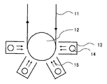
- a mechanism as shown in FIG. 3 is given as an example.
- the film 11 in which the composition for forming an optically anisotropic layer is applied to the surface of the alignment film is conveyed in the direction of the arrow in FIG.
- the film is conveyed while contacting the backup roll 12.
- the surface on which the composition for forming an optically anisotropic layer is applied is the surface of the substrate opposite to the surface in contact with the backup roll 12, and becomes the surface of the lamp house 13.
- the light irradiation is usually performed by visible light, ultraviolet light or laser light, and ultraviolet light is preferable.
- the light irradiation is performed with the lamp house 13 close to the backup roll 12 as shown in FIG.
- a lamp 14 is installed in the lamp house 13, and the illuminance can be controlled by adjusting the distance between the lamp 14 and the film 11.
- An arrow 15 in FIG. 3 represents light.
- it is a grade which does not leak nitrogen exceeding the supply-and-exhaust amount in the lamp house 13, without contacting an application surface.
- the light irradiation may be performed as it is on the applied optical anisotropic layer forming composition.
- the optical anisotropic layer forming composition contains a solvent
- the light irradiation is performed after drying and removing the solvent. Is preferred.
- the solvent By removing the solvent from the applied optical anisotropic layer forming composition, the polymerizable liquid crystal compound contained in the optical anisotropic layer forming composition forms liquid crystal alignment. Drying (removal of the solvent) may be performed in parallel with the light irradiation, but it is preferable to remove most of the solvent before the light irradiation. Examples of the drying method include the same methods as the drying method at the time of forming the alignment film. Of these, natural drying or heat drying is preferred.
- the drying temperature is preferably in the range of 0 ° C to 250 ° C, more preferably in the range of 50 ° C to 220 ° C, and still more preferably in the range of 60 ° C to 170 ° C.
- the drying time is preferably 10 seconds to 60 minutes, more preferably 30 seconds to 30 minutes.
- the following steps (1), (2) and (3) are preferably carried out continuously on a roll-shaped substrate, and the following (1), (2) and (2) -2) and (3) are more preferably carried out continuously.
- a step of forming an alignment film on a roll-shaped substrate (2)
- a step of applying an optical anisotropic layer forming composition containing a polymerizable liquid crystal compound and a photopolymerization initiator to the surface of the formed alignment film (2-2) Step of drying the applied optical anisotropic layer forming composition to align the polymerizable liquid crystal compound with liquid crystal (3)
- the thickness of the optically anisotropic film thus obtained can be appropriately adjusted depending on the application, but is preferably 0.1 ⁇ m to 10 ⁇ m, and more preferably 0.2 ⁇ m to 5 ⁇ m in terms of reducing photoelasticity. .
- the optically anisotropic film produced by the production method of the present invention (hereinafter sometimes referred to as the present optically anisotropic film) is formed on the surface of the alignment film formed on the substrate surface, it remains as it is. You may use, You may remove and use a base material or a base material and an oriented film.
- the optically anisotropic film which does not have a substrate or a substrate and an alignment film is usually combined with other members such as a polarizing film via an adhesive.
- a method of bonding the optically anisotropic film having no base material or a base material and an alignment film to other members using an adhesive And after bonding this optically anisotropic film formed on the surface of the alignment film formed on the surface of the base material to another member using an adhesive, the base material, or the base material and the alignment film are removed.
- the adhesive may be applied to the optically anisotropic film or may be applied to other members.
- optically anisotropic films those in which a polymerizable liquid crystal compound is vertically aligned convert linearly polarized light to circularly polarized light or elliptically polarized light when confirmed from the oblique angle on the light exit side, or circularly polarized light or elliptically polarized light linearly. It is useful as a retardation film used for converting into polarized light or changing the polarization direction of linearly polarized light.
- the retardation film is excellent in transparency in the visible light region and can be used as various display device members.
- This optically anisotropic film may be laminated in plural or in combination with other films. Laminating a plurality of the optically anisotropic films having different alignment states of the polymerizable liquid crystal compound, or combining the optically anisotropic film with another film, a viewing angle compensation film, a viewing angle widening film, and an antireflection film. It can be used as a film, a polarizing plate, a circularly polarizing plate, an elliptical polarizing plate or a brightness enhancement film.
- the optically anisotropic film can change the optical properties depending on the alignment state of the polymerizable liquid crystal compound, and includes a VA (vertical alignment) mode, an IPS (in-plane switching) mode, an OCB (optically compensated bend) mode, and a TN. It can be used as a retardation film for various liquid crystal display devices such as (twisted nematic) mode and STN (super twisted nematic) mode.
- optically anisotropic film the refractive index in a slow axis direction in a plane n x, the refractive index n y in the direction (fast axis direction) perpendicular to the slow axis in the plane, the refractive index in the thickness direction
- nz the refractive index in the thickness direction
- This optically anisotropic film is particularly preferably used as a positive C plate.
- the front retardation value Re (549) may be adjusted in the range of 0 to 10 nm, preferably in the range of 0 to 5 nm.
- the value R th is generally in the range of -10 ⁇ -300 nm, preferably may be adjusted in the range of -20 ⁇ -200 nm.
- the front retardation value Re (549) is preferably selected according to the characteristics of the liquid crystal cell, and is particularly suitable for compensation of an IPS mode liquid crystal display device.
- the thickness direction retardation value R th which means the refractive index anisotropy in the thickness direction of the optically anisotropic film is a retardation value R 50 measured by inclining 50 degrees with the in-plane fast axis as the tilt axis. And the in-plane retardation value R 0 .
- the retardation value R th in the thickness direction is the in-plane retardation value R 0
- the film thickness d the average of the film
- n 0 , n x , ny and nz can be obtained by the following formulas (9) to (11), and can be calculated by substituting these into formula (8).
- Rth [( nx + ny ) / 2- nz ] * d (8)
- R 0 (n x -n y ) ⁇ d (9)
- ny ′ ny ⁇ nz / [ ny 2 ⁇ sin 2 ( ⁇ ) + nz 2 ⁇ cos 2 ( ⁇ )] 1/2
- This optical anisotropic film suppresses the occurrence of orientation defects.
- alignment defects occur frequently, the uniformity of the surface of the liquid crystal layer is deteriorated, so that scattering occurs and the haze value increases.
- the haze is suppressed to 1% or less, and the transparency is reduced. A high film can be obtained.
- a commercially available haze meter can be used.
- a haze meter (model HZ-2) manufactured by Suga Test Instruments Co., Ltd. can be used.
- This optically anisotropic film is also useful as a member constituting a polarizing plate.
- the polarizing plate of the present invention includes at least one of the present optically anisotropic film and may be included as a retardation film.
- Specific examples of the polarizing plate include polarizing plates shown in FIGS. 1 (a) to 1 (e).
- a polarizing plate 4a shown in FIG. 1 (a) is a polarizing plate in which a retardation film 1 and a polarizing film 2 are directly laminated, and a polarizing plate 4b shown in FIG. 1 (b) is a retardation film. 1 and the polarizing film 2 are the polarizing plates bonded together through adhesive layer 3 '.
- a polarizing plate 4d shown in FIG. 1 (d) is obtained by laminating a retardation film 1 and a retardation film 1 ′ via an adhesive layer 3, and further laminating a polarizing film 2 on the retardation film 1 ′. It is the made polarizing plate.
- a polarizing plate 4e shown in FIG. 1 (e) is obtained by bonding a retardation film 1 and a retardation film 1 ′ through an adhesive layer 3, and further bonding the retardation film 1 ′ and the polarizing film 2 together.
- polarizing plate It is a polarizing plate bonded through an agent layer 3 ′.
- Adhesive means a general term for an adhesive and / or an adhesive. Said retardation film and polarizing film may have a base material, and do not need to have it.
- the polarizing film 2 may be a film having a polarizing function.
- the film include a stretched film on which a dye having absorption anisotropy is adsorbed and a film coated with a dye having absorption anisotropy.
- the dye having absorption anisotropy include dichroic dyes such as iodine and azo compounds.
- a film coated with a dye having absorption anisotropy a film obtained by applying a composition containing a dichroic dye having liquid crystallinity or a composition containing a dichroic dye and a polymerizable liquid crystal compound, etc. Is mentioned.
- the film having a polarizing function preferably has a protective film on one side or both sides thereof.
- Examples of the protective film include the same ones as described above.
- stretched film on which the dye having absorption anisotropy is adsorbed include the polarizing plates described in Japanese Patent No. 3708062, Japanese Patent No. 4432487, and the like.
- film coated with the pigment having absorption anisotropy include polarizing films described in JP 2012-33249 A and the like.
- the adhesive forming the adhesive layer 3 and the adhesive layer 3 ′ is preferably an adhesive having high transparency and excellent heat resistance.
- adhesives include acrylic adhesives, epoxy adhesives, and urethane adhesives.
- the polarization degree of the polarizing plate having the optically anisotropic film is usually 99.9% or more, and preferably 99.97% or more.
- This optically anisotropic film can be used for a display device.
- the display device include a liquid crystal display device including a liquid crystal panel in which the optically anisotropic film and the liquid crystal panel are bonded.
- a liquid crystal display device will be described as an embodiment of a display device provided with the optically anisotropic film.
- Examples of the liquid crystal display device include liquid crystal display devices 10a and 10b shown in FIGS. 2 (a) and 2 (b).
- the polarizing plate 4 and the liquid crystal panel 6 of the present invention are bonded together via an adhesive layer 5.
- the polarizing plate 4 of the present invention is on one surface of the liquid crystal panel 6, the polarizing plate 4 'of the present invention is on the other surface of the liquid crystal panel 6, and the adhesive layer 5 and It has a structure in which the adhesive layers 5 'are bonded to each other.
- an electrode not shown
- Table 1 shows the composition of the alignment film composition.
- the alignment film composition (A) was prepared by adding N-methyl-2-pyrrolidone, 2-butoxyethanol and ethylcyclohexane to a commercially available alignment polymer, Sunever SE-610 (manufactured by Nissan Chemical Industries, Ltd.).
- Table 1 The values in parentheses in Table 1 represent the content ratio of each component with respect to the total amount of the prepared composition.
- SE-610 the solid content was converted from the concentration described in the delivery specification.
- Table 2 shows the composition of the composition for forming an optically anisotropic layer. After mixing each component and stirring the obtained solution at 80 degreeC for 1 hour, it cooled to room temperature and obtained the composition (B) for optically anisotropic layer formation.
- the polymerizable liquid crystal compound (X-1) was produced by the method described in JP 2010-1284 A.
- Table 2 The values in parentheses in Table 2 represent the content ratio of each component with respect to the total amount of the prepared composition.
- LR-9000 is BASF Japan's Laromer (registered trademark) LR-9000
- Irg907 is BASF Japan's Irgagua 907
- BYK361N is Big Chemie Japan's leveling agent
- X-1 Represents a liquid crystal compound produced by BASF, represented by the following formula
- PGMEGA represents propylene glycol 1-monomethyl ether 2-acetate.
- Example 1 [Production Example 1 of Optically Anisotropic Film]
- the surface of the cycloolefin polymer film (ZF-14, manufactured by Nippon Zeon Co., Ltd.) is 1 under the conditions of an output of 0.3 kW and a processing speed of 3 m / min using a corona treatment device (AGF-B10, Kasuga Electric Co., Ltd.) Processed once.
- the alignment film composition (A) was applied to the surface of the cycloolefin polymer film obtained by performing the corona treatment, and dried to form an alignment film having a thickness of 50 nm.
- the optically anisotropic layer forming composition (B) was applied to the surface of the alignment film using a bar coater, heated to 100 ° C., dried, and cooled to room temperature.
- the surface of the obtained film on which the alignment film is not formed is brought into contact with a hot plate at 70 ° C., the oxygen concentration in the atmosphere is set to 900 ppm, and the wavelength is set using UniCure (VB-15201BY-A, manufactured by USHIO INC.).
- Polymerization was performed by irradiating 365 nm light at an illuminance of 40 mW / cm 2 for 30 seconds to produce an optically anisotropic film 1. It was 1.5 micrometers when the film thickness of the optically anisotropic layer was measured using the laser microscope (LEXT3000, Olympus company make).
- Comparative Example 1 [Production Example 1 for Comparative Optical Anisotropic Film] In Example 1, except that the temperature of the hot plate was set to 100 ° C., it was carried out under the same conditions as in Example 1, and a comparative optical anisotropic film 1 was produced. It was 1.5 micrometers when the film thickness of the optically anisotropic layer was measured using the laser microscope (LEXT3000, Olympus company make).
- Comparative Example 2 [Production Example 2 for Comparative Optical Anisotropic Film]
- Example 1 except that the oxygen concentration of the atmosphere at the time of light irradiation was 10000 ppm, it was carried out under the same conditions as in Example 1, and a comparative optical anisotropic film 2 was produced. It was 1.5 micrometers when the film thickness of the optically anisotropic layer was measured using the laser microscope (LEXT3000, Olympus company make).
- a polarizing plate (iodine normal polarizing plate TRW842AP7 manufactured by Sumitomo Chemical Co., Ltd.) was bonded to the optical anisotropic film 1 and the comparative optical anisotropic films 1 and 2 using an adhesive.
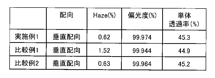
- the polarization degree of the obtained polarizing plate with an optically anisotropic film was measured with a spectrophotometer with an integrating sphere (manufactured by JASCO Corporation, V7100). MD transmittance and TD transmittance at a wavelength of 550 nm were determined, and single transmittance and degree of polarization were calculated based on the following formulas (12) and (13). The results are shown in Table 3.
- the MD transmittance is the transmittance when the direction of polarized light emitted from the Glan-Thompson prism is parallel to the transmission axis of the polarizing plate sample with the optically anisotropic film, and in the equations (12) and (13), Expressed as “MD”.
- the TD transmittance is a transmittance when the direction of polarized light emitted from the Glan-Thompson prism and the transmission axis of the polarizing plate with an optically anisotropic film are orthogonal to each other in the equations (12) and (13). Represents “TD”.
- Single transmittance (%) (MD + TD) / 2 (12)
- Degree of polarization (%) ⁇ ⁇ (MD ⁇ TD) / (MD + TD) ⁇ ⁇ 100 Formula (13)
- the optically anisotropic film 1 was found to be excellent in transparency and durability of optical anisotropy.
- Optically anisotropic film 1, comparative optically anisotropic film 1 and 2 were positive C plate n x ⁇ n y ⁇ n z .
- Example 2 [Production Example 2 of optically anisotropic film] An optically anisotropic film 2 was prepared in the same manner as in Example 1. It was 1.0 micrometer when the film thickness of the optically anisotropic layer was measured using the laser microscope (LEXT3000, Olympus company make). The optical properties were measured by the same method as for the optically anisotropic film 1, and the refractive index was calculated. The results are shown in Table 6.
- Comparative Example 3 [Production Example 3 for Comparative Optical Anisotropic Film]
- a comparative optical anisotropic film 3 was prepared in the same manner as in Comparative Example 1, except that the oxygen concentration in the atmosphere during light irradiation was set to 10,000 ppm. It was 1.0 micrometer when the film thickness of the optically anisotropic layer was measured using the laser microscope (LEXT3000, Olympus company make). The optical properties were measured by the same method as for the optically anisotropic film 1, and the refractive index was calculated. The results are shown in Table 6.
- a polarizing plate was laminated on the surface on the optically anisotropic layer side. At this time, lamination was performed so that the transmission axis of the polarizing plate and the slow axis of the cycloolefin polymer film were substantially orthogonal.
- the obtained polarizing plate with an optically anisotropic film is bonded to the viewing side of i-Pad (registered trademark) (manufactured by Apple) from which the polarizing plate on the viewing side has been removed, and light leakage occurs when black is displayed.
- the panel surface was visually observed from the direction of azimuth angle 45 ° and elevation angle 45 °.
- the comparative optically anisotropic film 3 was also evaluated in the same manner. The results are shown in Table 6.
- Optically anisotropic films 2 and comparative optically anisotropic film 3 was positive C plate n x ⁇ n y ⁇ n z .
- the optically anisotropic film 2 when used, there was no light leakage and black was displayed during black display.
- the comparative optically anisotropic film 3 when the comparative optically anisotropic film 3 was used, there was light leakage and during black display. I knew it would be white.
- an optically anisotropic film excellent in transparency and durability of optical anisotropy can be produced.
Landscapes
- Physics & Mathematics (AREA)
- Chemical & Material Sciences (AREA)
- Crystallography & Structural Chemistry (AREA)
- General Physics & Mathematics (AREA)
- Optics & Photonics (AREA)
- Liquid Crystal (AREA)
- Polarising Elements (AREA)
- Laminated Bodies (AREA)
- Health & Medical Sciences (AREA)
- Chemical Kinetics & Catalysis (AREA)
- Medicinal Chemistry (AREA)
- Polymers & Plastics (AREA)
- Organic Chemistry (AREA)
Abstract
Description
[1] 以下の(1)及び(2)の工程を含む光学異方性フィルムの製造方法。
(1)配向膜の表面に、重合性液晶化合物及び光重合開始剤を含む光学異方層形成用組成物を塗布する工程
(2)塗布された光学異方層形成用組成物を、酸素濃度0.5%以下の雰囲気下で、重合性液晶化合物の液晶−液体相転移温度以下に保持しながら、該光学異方層形成用組成物に光を照射する工程
[2] 工程(2)における、塗布された光学異方層形成用組成物を保持する温度が80℃以下である[1]に記載の光学異方性フィルムの製造方法。
[3] 工程(2)における、塗布された光学異方層形成用組成物に光を照射する時間が5秒~10分である[1]又は[2]に記載の光学異方性フィルムの製造方法。
[4] 工程(2)における、酸素濃度が0.1%以下である[1]~[3]のいずれかに記載の光学異方性フィルムの製造方法。
[5] 配向膜が基材表面に形成されている[1]~[4]のいずれかに記載の光学異方性フィルの製造方法。
[6] 配向膜が形成された基材表面の反対側の面を冷媒循環ロールに接触させて、基材表面を80℃以下に保持しながら光照射する[5]に記載の光学異方性フィルムの製造方法。
[7] 冷媒循環ロールに流す冷媒の温度が4~30℃である[6]に記載の光学異方性フィルムの製造方法。
[8] 配向膜が形成された基材表面の反対側の面を冷媒循環ロールに接触させる時間が5秒~10分である[6]又は[7]に記載の光学異方性フィルムの製造方法。
[9] 基材がロール状の基材であり、[1]に記載の(1)及び(2)の工程を連続して実施する[5]~[8]のいずれかに記載の光学異方性フィルムの製造方法。
[10] 以下の(1)及び(2)の工程を実施することにより得られる光学異方性フィルム。
(1)配向膜の表面に、重合性液晶化合物及び光重合開始剤を含む光学異方層形成用組成物を塗布する工程
(2)塗布された光学異方層形成用組成物を、酸素濃度0.5%以下の雰囲気下で、重合性液晶化合物の液晶−液体相転移温度以下に保持しながら、該光学異方層形成用組成物に光を照射する工程
[11] 垂直配向した重合性液晶化合物から形成された[10]に記載の光学異方性フィルム。
[12] 正面位相差値Re(549)が0~10nmであり、厚み方向の位相差値Rthが−10~−300nmである[10]又は[11]に記載の光学異方性フィルム。
[13] IPS(in−plane switching)液晶表示装置用の[10]~[12]のいずれかに記載の光学異方性フィルム。
[14] [10]~[13]のいずれかに記載の光学異方性フィルムを有する偏光板。
[15] 偏光度が99.97%以上である、[14]に記載の偏光板。
[16] [10]~[13]のいずれかに記載の光学異方性フィルムを備えた表示装置。
(1)配向膜の表面に、重合性液晶化合物及び光重合開始剤を含む光学異方層形成用組成物を塗布する工程
(2)塗布された光学異方層形成用組成物を、酸素濃度0.5%以下の雰囲気下で、重合性液晶化合物の液晶−液体相転移温度以下に保持しながら、該光学異方層形成用組成物に光を照射する工程
配向性ポリマー及び光配向性ポリマーは、通常、溶剤に溶解して塗布される。
市販の配向性ポリマーとしては、サンエバー(登録商標、日産化学社製)、オプトマー(登録商標、JSR製)等が挙げられる。
このような配向性ポリマーから形成される配向膜は、重合性液晶化合物の液晶配向を容易にする。また、配向性ポリマーの種類やラビング条件によって、水平配向、垂直配向、ハイブリッド配向、傾斜配向等の様々な液晶配向の制御が可能であり、各種液晶パネルの視野角改善等に利用できる。
配向膜の厚さが上記範囲にあると、重合性液晶化合物を所望の方向や角度に容易に液晶配向させることができるため好ましい。
P11−B11−E11−B12−A11−B13− (X)
[式(X)中、P11は、重合性基を表わす。
A11は、2価の脂環式炭化水素基または2価の芳香族炭化水素基を表わす。該2価の脂環式炭化水素基および2価の芳香族炭化水素基に含まれる水素原子は、ハロゲン原子、炭素数1~6のアルキル基、炭素数1~6アルコキシ基、シアノ基またはニトロ基で置換されていてもよく、該炭素数1~6のアルキル基および該炭素数1~6アルコキシ基に含まれる水素原子は、フッ素原子で置換されていてもよい。
B11は、−O−、−S−、−CO−O−、−O−CO−、−O−CO−O−、−CO−NR16−、−NR16−CO−、−CO−、−CS−または単結合を表わす。R16は、水素原子または炭素数1~6のアルキル基を表わす。
B12およびB13は、それぞれ独立に、−C≡C−、−CH=CH−、−CH2−CH2−、−O−、−S−、−C(=O)−、−C(=O)−O−、−O−C(=O)−、−O−C(=O)−O−、−CH=N−、−N=CH−、−N=N−、−C(=O)−NR16−、−NR16−C(=O)−、−OCH2−、−OCF2−、−CH2O−、−CF2O−、−CH=CH−C(=O)−O−、−O−C(=O)−CH=CH−または単結合を表わす。
E11は、炭素数1~12のアルカンジイル基を表わし、該アルカンジイル基に含まれる水素原子は、炭素数1~5のアルコキシ基で置換されていてもよく、該アルコキシ基に含まれる水素原子は、ハロゲン原子で置換されていてもよい。また、該アルカンジイル基を構成する−CH2−は、−O−または−CO−に置き換わっていてもよい。]
具体的には、メチレン基、エチレン基、プロパン−1,3−ジイル基、ブタン−1,4−ジイル基、ペンタン−1,5−ジイル基、ヘキサン−1,6−ジイル基、ヘプタン−1,7−ジイル基、オクタン−1,8−ジイル基、ノナン−1,9−ジイル基、デカン−1,10−ジイル基、ウンデカン−1,11−ジイル基およびドデカン−1,12−ジイル基等の炭素数1~12の直鎖状アルカンジイル基;−CH2−CH2−O−CH2−CH2−、−CH2−CH2−O−CH2−CH2−O−CH2−CH2−および−CH2−CH2−O−CH2−CH2−O−CH2−CH2−O−CH2−CH2−等が挙げられる。
B11としては、−O−、−S−、−CO−O−、−O−CO−が好ましく、中でも、−CO−O−がより好ましい。
B12およびB13としては、それぞれ独立に、−O−、−S−、−C(=O)−、−C(=O)−O−、−O−C(=O)−、−O−C(=O)−O−が好ましく、中でも、−O−または−O−C(=O)−O−がより好ましい。

R17~R21はそれぞれ独立に、炭素数1~6のアルキル基または水素原子を表わす。]
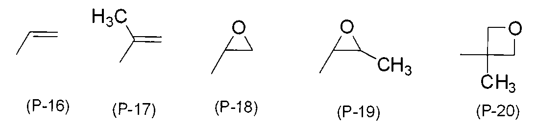
P11−B11−で表わされる基が、アクリロイルオキシ基またはメタアクリロイルオキシ基であることがさらに好ましい。
P11−B11−E11−B12−A11−B13−A12−B14−A13−B15−A14−B16−E12−B17−P12 (I)
P11−B11−E11−B12−A11−B13−A12−B14−A13−B15−A14−F11 (II)
P11−B11−E11−B12−A11−B13−A12−B14−A13−B15−E12−B17−P12 (III)
P11−B11−E11−B12−A11−B13−A12−B14−A13−F11 (IV)
P11−B11−E11−B12−A11−B13−A12−B14−E12−B17−P12 (V)
P11−B11−E11−B12−A11−B13−A12−F11 (VI)
(式中、
A12~A14はそれぞれ独立に、A11と同義であり、B14~B16はそれぞれ独立に、B12と同義であり、B17は、B11と同義であり、E12は、E11と同義である。
F11は、水素原子、炭素数1~13のアルキル基、炭素数1~13のアルコキシ基、シアノ基、ニトロ基、トリフルオロメチル基、ジメチルアミノ基、ヒドロキシ基、メチロール基、ホルミル基、スルホ基(−SO3H)、カルボキシ基、炭素数1~10のアルコキシカルボニル基またはハロゲン原子を表わし、該アルキル基およびアルコキシ基を構成する−CH2−は、−O−に置き換っていてもよい。



光重合開始剤としては、ベンゾイン化合物、ベンゾフェノン化合物、ベンジルケタール化合物、α−ヒドロキシケトン化合物、α−アミノケトン化合物、α−アセトフェノン化合物、トリアジン化合物、ヨードニウム塩およびスルホニウム塩が挙げられる。具体的には、イルガキュア(Irgacure)907、イルガキュア184、イルガキュア651、イルガキュア819、イルガキュア250、イルガキュア369(以上、全てチバ・ジャパン株式会社製)、セイクオールBZ、セイクオールZ、セイクオールBEE(以上、全て精工化学株式会社製)、カヤキュアー(kayacure)BP100(日本化薬株式会社製)、カヤキュアーUVI−6992(ダウ社製)、アデカオプトマーSP−152、アデカオプトマーSP−170(以上、全て株式会社ADEKA製)、TAZ−A、TAZ−PP(以上、日本シイベルヘグナー社製)およびTAZ−104(三和ケミカル社製)等が挙げられる。中でも、α−アセトフェノン化合物が好ましく、α−アセトフェノン化合物としては、2−メチル−2−モルホリノ−1−(4−メチルスルファニルフェニル)プロパン−1−オン、2−ジメチルアミノ−1−(4−モルホリノフェニル)−2−ベンジルブタン−1−オン及び2−ジメチルアミノ−1−(4−モルホリノフェニル)−2−(4−メチルフェニルメチル)ブタン−1−オン等が挙げられ、より好ましくは2−メチル−2−モルホリノ−1−(4−メチルスルファニルフェニル)プロパン−1−オン及び2−ジメチルアミノ−1−(4−モルホリノフェニル)−2−ベンジルブタン−1−オンが挙げられる。α−アセトフェノン化合物の市販品としては、イルガキュア369、379EG、907(以上、BASFジャパン(株)製)及びセイクオールBEE(精工化学社製)等が挙げられる。
重合禁止剤は、重合性液晶化合物の重合反応をコントロールすることができる。
重合禁止剤としては、ハイドロキノンおよびアルキルエーテル等の置換基を有するハイドロキノン類;ブチルカテコール等のアルキルエーテル等の置換基を有するカテコール類;ピロガロール類、2,2,6,6−テトラメチル−1−ピペリジニルオキシラジカル等のラジカル補足剤;チオフェノール類;β−ナフチルアミン類およびβ−ナフトール類が挙げられる。
光学異方層形成用組成物における重合禁止剤の含有量は、重合性液晶化合物100質量部に対して、通常0.1質量部~30質量部であり、好ましくは0.5質量部~10質量部である。上記範囲内であれば、重合性液晶化合物の液晶配向を乱すことなく、重合することができる。
光増感剤としては、キサントン、チオキサントン等のキサントン類;アントラセンおよびアルキルエーテル等の置換基を有するアントラセン類;フェノチアジン;ルブレンが挙げられる。
光増感剤を用いることにより、光重合開始剤を高感度化することができる。光増感剤の含有量は、重合性液晶化合物100質量部に対して、通常0.1質量部~30質量部であり、好ましくは0.5質量部~10質量部である。
レベリング剤としては、有機変性シリコーンオイル系、ポリアクリレート系およびパーフルオロアルキル系のレベリング剤が挙げられる。具体的には、DC3PA、SH7PA、DC11PA、SH28PA、SH29PA、SH30PA、ST80PA、ST86PA、SH8400、SH8700、FZ2123(以上、全て東レ・ダウコーニング(株)製)、KP321、KP323、KP324、KP326、KP340、KP341、X22−161A、KF6001(以上、全て信越化学工業(株)製)、TSF400、TSF401、TSF410、TSF4300、TSF4440、TSF4445、TSF−4446、TSF4452、TSF4460(以上、全てモメンティブ パフォーマンス マテリアルズ ジャパン合同会社製)、フロリナート(fluorinert)(登録商標)FC−72、同FC−40、同FC−43、同FC−3283(以上、全て住友スリーエム(株)製)、メガファック(登録商標)R−08、同R−30、同R−90、同F−410、同F−411、同F−443、同F−445、同F−470、同F−477、同F−479、同F−482、同F−483(以上、いずれもDIC(株)製)、エフトップ(商品名)EF301、同EF303、同EF351、同EF352(以上、全て三菱マテリアル電子化成(株)製)、サーフロン(登録商標)S−381、同S−382、同S−383、同S−393、同SC−101、同SC−105、KH−40、SA−100(以上、全てAGCセイミケミカル(株)製)、商品名E1830、同E5844((株)ダイキンファインケミカル研究所製)、BM−1000、BM−1100、BYK−352、BYK−353及びBYK−361N(いずれも商品名:BM Chemie社製)が挙げられる。2種以上のレベリング剤を組み合わせてもよい。
カイラル剤としては、公知のカイラル剤(例えば、液晶デバイスハンドブック、第3章4−3項、TN、STN用カイラル剤、199頁、日本学術振興会第142委員会編、1989に記載)が挙げられる。
カイラル剤は、一般に不斉炭素原子を含むが、不斉炭素原子を含まない軸性不斉化合物あるいは面性不斉化合物もカイラル剤として用いることができる。軸性不斉化合物または面性不斉化合物としては、ビナフチル、ヘリセン、パラシクロファンおよびこれらの誘導体が挙げられる。
具体的には、特開2007−269640号公報、特開2007−269639号公報、特開2007−176870号公報、特開2003−137887号公報、特表2000−515496号公報、特開2007−169178号公報および特表平9−506088号公報に記載されているような化合物が挙げられ、好ましくはBASFジャパン(株)製のpaliocolor(登録商標) LC756である。
カイラル剤の含有量は、重合性液晶化合物100質量部に対して、通常0.1質量部~30質量部であり、好ましくは1.0質量部~25質量部である。上記範囲内であれば、重合性液晶化合物を重合する際に、該重合性液晶化合物の液晶配向を乱すことをより抑制できる。
反応性添加剤としては、その分子内に炭素−炭素不飽和結合と活性水素反応性基とを有するものが好ましい。なお、ここでいう「活性水素反応性基」とは、カルボキシル基(−COOH)、水酸基(−OH)、アミノ基(−NH2)等の活性水素を有する基に対して反応性を有する基を意味し、グリシジル基、オキサゾリン基、カルボジイミド基、アジリジン基、イミド基、イソシアナト基、チオイソシアナト基、無水マレイン酸基等がその代表例である。

nは1~10までの整数を表わし、R1’は、炭素数2~20の2価の脂肪族又は脂環式炭化水素基、或いは炭素数5~20の2価の芳香族炭化水素基を表わす。各繰り返し単位にある2つのR2’は、一方が−NH−であり、他方が>N−C(=O)−R3’で示される基である。R3’は、水酸基又は炭素−炭素不飽和結合を有する基を表す。
式(Y)中のR3’のうち、少なくとも1つのR3’は炭素−炭素不飽和結合を有する基である。]

光学異方層形成用組成物は、光学異方性フィルム製造の操作性を良好にするために溶剤、特に有機溶剤を含むことが好ましい。有機溶剤としては、重合性液晶化合物等の光学異方層形成用組成物の構成成分を溶解し得る有機溶剤が好ましく、重合性液晶化合物等の光学異方層形成用組成物の構成成分を溶解し得る溶剤であって、且つ、重合性液晶化合物の重合反応に不活性な溶剤がより好ましい。具体的には、メタノール、エタノール、エチレングリコール、イソプロピルアルコール、プロピレングリコール、メチルセロソルブ、ブチルセロソルブ、プロピレングリコールモノメチルエーテル、フェノール等のアルコール溶剤;酢酸エチル、酢酸ブチル、エチレングリコールメチルエーテルアセテート、γ−ブチロラクトン、プロピレングリコールメチルエーテルアセテート、乳酸エチル等のエステル溶剤;アセトン、メチルエチルケトン、シクロペンタノン、シクロヘキサノン、メチルアミルケトン、メチルイソブチルケトン等のケトン溶剤;ペンタン、ヘキサン、ヘプタン等の非塩素化脂肪族炭化水素溶剤;トルエン、キシレン等の非塩素化芳香族炭化水素溶剤;アセトニトリル等のニトリル溶剤;テトラヒドロフラン、ジメトキシエタン等のエーテル溶剤;およびクロロホルム、クロロベンゼン等の塩素化炭化水素溶剤;が挙げられる。
二種以上の有機溶剤を組み合わせて用いてもよい。中でも、アルコール溶剤、エステル溶剤、ケトン溶剤、非塩素化脂肪族炭化水素溶剤および非塩素化芳香族炭化水素溶剤が好ましい。
垂直配向した重合性液晶化合物は、重合性基を、光学異方層形成用組成物と雰囲気との界面近くに分布しやすいため、前記重合性液晶化合物の重合反応は雰囲気の環境に強く影響される傾向がある。よって本発明の製造方法により製造される光学異方性フィルムの中でも、垂直配向された重合性液晶化合物を含む光学異方層形成用組成物に光を照射することで得られるものは、本発明の効果をより強く奏するため、従来品に比較してより優れた透明性及び光学異方性の耐久性を示す。
配向規制力は、配向膜が配向性ポリマーから形成されている場合は、表面状態やラビング条件によって任意に調整することが可能であり、光配向性ポリマーから形成されている場合は、偏光照射条件等によって任意に調整することが可能である。また、重合性液晶化合物の、表面張力や液晶性等の物性を選択することにより、液晶配向を制御することもできる。
光照射時の気圧は通常、大気圧である。
液晶−液体相転移温度以下の温度範囲の中でも、80℃以下が好ましく、70℃以下がより好ましく、60℃以下がさらに好ましい。また、30℃以上が好ましく、40℃以上がより好ましく、50℃以上がさらに好ましい。光照射時の温度が80℃以下であると、液晶配向のゆらぎを抑制するため欠陥が生じにくくなり、また基材への熱的影響も抑制することができるため好ましい。当該温度に保温する方法としては、光照射時に空気や窒素を流し込み換気をする方法や、フィルム搬送のバックアップロール内に冷媒を流すことで配向膜が形成された基材表面の反対側の面から冷却する方法等が挙げられる。中でも、冷媒を流すことができるバックアップロールである冷媒循環ロールに、基材の配向膜が形成された基材表面の反対側の面を接触させて光照射することが好ましい。上記方法で得られる光学異方性フィルムは透明性に優れ、また、表示装置に実装した時の光漏れを抑制することができる。
(1)ロール状の基材に配向膜を形成する工程
(2)形成された配向膜の表面に、重合性液晶化合物及び光重合開始剤を含む光学異方層形成用組成物を塗布する工程
(2−2)塗布された光学異方層形成用組成物を乾燥して該重合性液晶化合物を液晶配向させる工程
(3)塗布又は乾燥された光学異方層形成用組成物を、酸素濃度0.5%以下の雰囲気下で、重合性液晶化合物の液晶−液体相転移温度以下に保持しながら、該光学異方層形成用組成物に光を照射する工程
基材、又は、基材及び配向膜を有さない本光学異方性フィルムは、通常、接着剤を介して偏光フィルム等のその他の部材と組み合わされる。
接着剤を介してその他の部材と組み合わせる方法としては、基材、又は、基材及び配向膜を有さない本光学異方性フィルムを、接着剤を用いてその他の部材へ貼合する方法、及び、基材表面に形成された配向膜の表面に形成された本光学異方性フィルムを、接着剤を用いてその他の部材へ貼合した後に基材、又は、基材及び配向膜を取り除く方法等が挙げられる。この際、接着剤は、本光学異方性フィルムに塗布されてもよく、その他の部材に塗布されてもよい。
前記位相差フィルムは、可視光領域における透明性に優れ、様々な表示装置用部材として使用し得る。
nx>ny≒nzのポジティブAプレート、
nx≒ny>nzのネガティブCプレート、
nx≒ny<nzのポジティブCプレート、
nx≠ny≠nzのポジティブOプレートおよびネガティブOプレート
R0 =(nx−ny)×d (9)
R50=(nx−ny’)×d/cos(φ) (10)
(nx+ny+nz)/3=n0 (11)
ここで、
φ=sin−1 〔sin(50°)/n0〕
ny’=ny×nz/〔ny 2×sin2(φ)+nz 2×cos2(φ)〕1/2
偏光板の具体例としては、図1(a)~図1(e)で示される偏光板が挙げられる。図1(a)で示される偏光板4aは、位相差フィルム1と、偏光フィルム2とが、直接積層された偏光板であり、図1(b)で示される偏光板4bは、位相差フィルム1と偏光フィルム2とが、接着剤層3’を介して貼り合わされた偏光板である。図1(c)で示される偏光板4cは、位相差フィルム1と、位相差フィルム1’とを積層させ、さらに、位相差フィルム1’と偏光フィルム2とを積層させた偏光板であり、図1(d)で示される偏光板4dは、位相差フィルム1と、位相差フィルム1’とを接着剤層3を介して貼り合わせ、さらに、位相差フィルム1’上に偏光フィルム2を積層させた偏光板である。図1(e)で示される偏光板4eは、位相差フィルム1と、位相差フィルム1’とを接着剤層3を介して貼り合わせ、さらに、位相差フィルム1’と偏光フィルム2とを接着剤層3’を介して貼り合せた偏光板である。”接着剤”とは、接着剤および/または粘着剤の総称を意味する。
上記の位相差フィルム及び偏光フィルムは、基材を有していてもよいし、有していなくてもよい。
前記吸収異方性を有する色素を塗布したフィルムとしては、具体的には、特開2012−33249号公報等に記載の偏光フィルムが挙げられる。
配向膜用組成物の組成を、表1に示す。市販の配向性ポリマーであるサンエバーSE−610(日産化学工業株式会社製)にN−メチル−2−ピロリドン、2−ブトキシエタノール及びエチルシクロヘキサンを加えてして配向膜用組成物(A)を調整した。

光学異方層形成用組成物の組成を、表2に示す。各成分を混合し、得られた溶液を80℃で1時間攪拌した後、室温に冷却し、光学異方層形成用組成物(B)を得た。重合性液晶化合物(X−1)は、特開2010−1284号公報に記載の方法で製造した。

表2におけるLR−9000は、BASFジャパン社製のLaromer(登録商標)LR−9000を、Irg907は、BASFジャパン社製のイルガギュア907を、BYK361Nは、ビックケミージャパン製のレベリング剤を、X−1は、下記式で示されるBASF社製の液晶化合物を、PGMEGAは、プロピレングリコール1−モノメチルエーテル2−アセタートを表す。
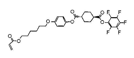
重合性液晶化合物(X−1)を、ホットステージ付偏光顕微鏡(ホットステージ:LTS350、Linkam社製、偏光顕微鏡:BX−51、オリンパス社製)を用いて、昇温速度30℃/minで加熱しながら観察した。重合性液晶化合物(X−1)は、69℃でスメクチック相に、79℃でネマチック相に、89℃で液体に相転移した。
シクロオレフィンポリマーフィルム(ZF−14、日本ゼオン株式会社製)の表面を、コロナ処理装置(AGF−B10、春日電機株式会社製)を用いて出力0.3kW、処理速度3m/分の条件で1回処理した。
コロナ処理を施して得られたシクロオレフィンポリマーフィルム表面に、配向膜用組成物(A)を塗布し、乾燥して、厚さ50nmの配向膜を形成した。続いて、光学異方層形成用組成物(B)を、バーコーターを用いて配向膜表面に塗布し、100℃に加熱し乾燥し、室温まで冷却した。得られたフィルムの配向膜が形成されていない表面を70℃のホットプレートに接触させ、雰囲気の酸素濃度を900ppmとし、ユニキュア(VB—15201BY−A、ウシオ電機株式会社製)を用いて、波長365nmの光を40mW/cm2の照度で30秒間照射することにより、重合を行い、光学異方性フィルム1を作製した。光学異方性層の膜厚をレーザー顕微鏡(LEXT3000、オリンパス社製)を用いて測定したところ、1.5μmであった。
上記実施例1において、ホットプレートの温度を100℃とした以外は、上記実施例1と同じ条件で実施し、比較用光学異方性フィルム1を作製した。光学異方性層の膜厚をレーザー顕微鏡(LEXT3000、オリンパス社製)を用いて測定したところ、1.5μmであった。
上記実施例1において、光照射時の雰囲気の酸素濃度を10000ppmとした以外は、上記実施例1と同じ条件で実施し、比較用光学異方性フィルム2を作製した。光学異方性層の膜厚をレーザー顕微鏡(LEXT3000、オリンパス社製)を用いて測定したところ、1.5μmであった。
スガ試験機株式会社製 ヘイズメーター(型式HZ−2)を用いて、ダブルビーム法で、光学異方性フィルム1、比較用光学異方性フィルム1および2のヘイズ値を測定した。結果を表3に示す。
光学異方性フィルム1、比較用光学異方性フィルム1および2の位相差値を測定機(KOBRA−WR、王子計測機器社製)により測定した。
サンプルへの光の入射角を変えて測定し、液晶が垂直配向しているかどうか確認した。結果を表3に示す。
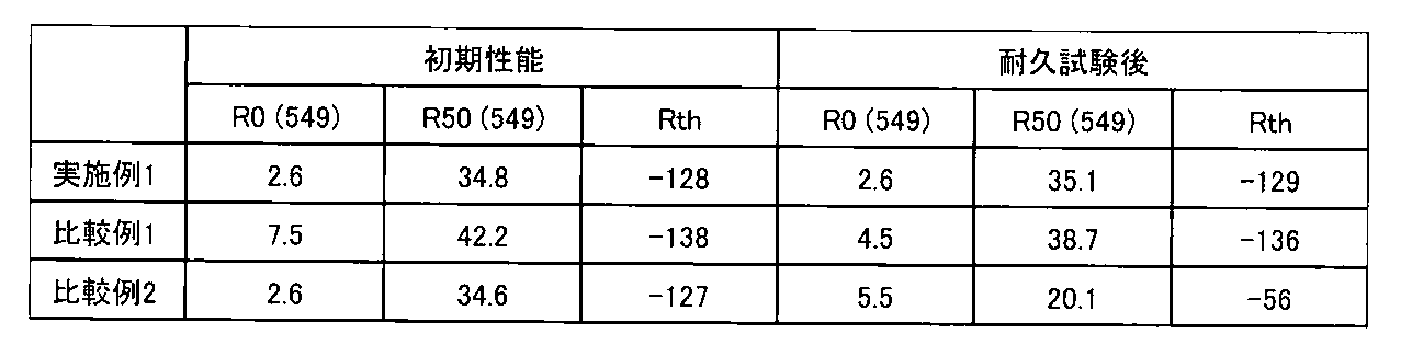
また、入射角0度(正面)の位相差値R0(λ)及び、入射角50度(進相軸まわりの傾斜)の位相差値R50(λ)を、それぞれ波長(λ)549nmにおいて測定した。結果を表4に示す。
得られた位相差値R0(549)及びR50(549)を用いて、上記式(9)~(11)から光学異方性フィルムの屈折率nx、ny及びnzを算出した。ここで、平均屈折率n0は1.6とした。結果を表5に示す。
光学異方性フィルム1、比較用光学異方性フィルム1および2に、偏光板(住友化学社製沃素系通常偏光板TRW842AP7)を、粘着剤を用いて貼合した。得られた光学異方性フィルム付き偏光板の偏光度を積分球付き分光光度計(日本分光(株)製、V7100)にて測定した。波長550nmにおけるMD透過率とTD透過率とを求め、以下の式(12)及び式(13)に基づいて単体透過率及び、偏光度を算出した。結果を表3に示す。
単体透過率(%)=(MD+TD)/2 ・・・・式(12)
偏光度(%)=√{(MD−TD)/(MD+TD)}×100 ・・・・式(13)
光学異方性フィルム表面に粘着剤を貼合し、80℃の加熱オーブンに投入した。500時間後の位相差値R0(549)およびR50(549)を測定して特性変化を確認した。結果を表4に示す。

実施例1と同様の方法により光学異方性フィルム2を作成した。光学異方性層の膜厚をレーザー顕微鏡(LEXT3000、オリンパス社製)を用いて測定したところ、1.0μmであった。光学異方性フィルム1と同様の方法で光学特性を測定し、屈折率を算出した。結果を表6に示す。
比較例1において、光照射時の雰囲気の酸素濃度を10000ppmとした以外は、比較例1と同様の方法により比較用光学異方性フィルム3を作成した。光学異方性層の膜厚をレーザー顕微鏡(LEXT3000、オリンパス社製)を用いて測定したところ、1.0μmであった。光学異方性フィルム1と同様の方法で光学特性を測定し、屈折率を算出した。結果を表6に示す。
光学異方性フィルム2の基材側の面に、粘着剤を用いてシクロオレフィンポリマーフィルム(位相差値R0(549)=110nm、厚さ=28μm)を貼合した。また、光学異方性層側の面に偏光板を積層した。この際、偏光板の透過軸と、シクロオレフィンポリマーフィルムの遅相軸とが略直交するように積層した。得られた光学異方性フィルム付偏光板を、視認側の偏光板を取り除いたi−Pad(登録商標)(アップル社製)の視認側に貼合し、黒表示させた時の光漏れを、パネル表面に対し方位角45°、仰角45°の方向から目視で観察した。
比較用光学異方性フィルム3についても、同様にして評価した。結果を表6に示す。

2、2’:偏光フィルム
3、3’:接着剤層
4a、4b、4c、4d、4e、4、4’:偏光板
5、5’:接着層
6:液晶パネル
10a、10b:液晶表示装置
11:光学異方性層形成用組成物が配向膜の表面に塗布されたフィルム
12:バックアップロール
13:ランプハウス
14:ランプ
15:光
Claims (16)
- 以下の(1)及び(2)の工程を含む光学異方性フィルムの製造方法。
(1)配向膜の表面に、重合性液晶化合物及び光重合開始剤を含む光学異方層形成用組成物を塗布する工程
(2)塗布された光学異方層形成用組成物を、酸素濃度0.5%以下の雰囲気下で、重合性液晶化合物の液晶−液体相転移温度以下に保持しながら、該光学異方層形成用組成物に光を照射する工程 - 工程(2)における、塗布された光学異方層形成用組成物を保持する温度が80℃以下である請求項1に記載の光学異方性フィルムの製造方法。
- 工程(2)における、塗布された光学異方層形成用組成物に光を照射する時間が5秒~10分である請求項1又は請求項2に記載の光学異方性フィルムの製造方法。
- 工程(2)における、酸素濃度が0.1%以下である請求項1~3のいずれかに記載の光学異方性フィルムの製造方法。
- 配向膜が基材表面に形成されている請求項1~4のいずれかに記載の光学異方性フィルの製造方法。
- 配向膜が形成された基材表面の反対側の面を冷媒循環ロールに接触させて、基材表面を80℃以下に保持しながら光照射する請求項5に記載の光学異方性フィルムの製造方法。
- 冷媒循環ロールに流す冷媒の温度が4~30℃である請求項6に記載の光学異方性フィルムの製造方法。
- 配向膜が形成された基材表面の反対側の面を冷媒循環ロールに接触させる時間が5秒~10分である請求項6又は請求項7に記載の光学異方性フィルムの製造方法。
- 基材がロール状の基材であり、請求項1に記載の(1)及び(2)の工程を連続して実施する請求項5~8のいずれかに記載の光学異方性フィルムの製造方法。
- 以下の(1)及び(2)の工程を実施することにより得られる光学異方性フィルム。
(1)配向膜の表面に、重合性液晶化合物及び光重合開始剤を含む光学異方層形成用組成物を塗布する工程
(2)塗布された光学異方層形成用組成物を、酸素濃度0.5%以下の雰囲気下で、重合性液晶化合物の液晶−液体相転移温度以下に保持しながら、該光学異方層形成用組成物に光を照射する工程 - 垂直配向した重合性液晶化合物から形成された請求項10に記載の光学異方性フィルム。
- 正面位相差値Re(549)が0~10nmであり、厚み方向の位相差値Rthが−10~−300nmである請求項10又は請求項11に記載の光学異方性フィルム。
- IPS(in−plane switching)液晶表示装置用の請求項10~12のいずれかに記載の光学異方性フィルム。
- 請求項10~13のいずれかに記載の光学異方性フィルムを有する偏光板。
- 偏光度が99.97%以上である、請求項14に記載の偏光板。
- 請求項10~13のいずれかに記載の光学異方性フィルムを備えた表示装置。
Priority Applications (3)
| Application Number | Priority Date | Filing Date | Title |
|---|---|---|---|
| KR1020157031682A KR20150143568A (ko) | 2013-04-11 | 2014-04-10 | 광학 이방성 필름의 제조 방법 |
| US14/392,100 US20160041320A1 (en) | 2013-04-11 | 2014-04-10 | Method for producing optically anisotropic film |
| JP2015511326A JPWO2014168258A1 (ja) | 2013-04-11 | 2014-04-10 | 光学異方性フィルムの製造方法 |
Applications Claiming Priority (2)
| Application Number | Priority Date | Filing Date | Title |
|---|---|---|---|
| JP2013082696 | 2013-04-11 | ||
| JP2013-082696 | 2013-04-11 |
Publications (1)
| Publication Number | Publication Date |
|---|---|
| WO2014168258A1 true WO2014168258A1 (ja) | 2014-10-16 |
Family
ID=51689658
Family Applications (1)
| Application Number | Title | Priority Date | Filing Date |
|---|---|---|---|
| PCT/JP2014/060884 Ceased WO2014168258A1 (ja) | 2013-04-11 | 2014-04-10 | 光学異方性フィルムの製造方法 |
Country Status (4)
| Country | Link |
|---|---|
| US (1) | US20160041320A1 (ja) |
| JP (1) | JPWO2014168258A1 (ja) |
| KR (1) | KR20150143568A (ja) |
| WO (1) | WO2014168258A1 (ja) |
Cited By (2)
| Publication number | Priority date | Publication date | Assignee | Title |
|---|---|---|---|---|
| JPWO2018079854A1 (ja) * | 2016-10-31 | 2019-07-25 | 富士フイルム株式会社 | 光学フィルムおよび液晶表示装置 |
| JP2021121862A (ja) * | 2019-02-04 | 2021-08-26 | 住友化学株式会社 | 偏光板および表示装置 |
Citations (5)
| Publication number | Priority date | Publication date | Assignee | Title |
|---|---|---|---|---|
| JP2004125841A (ja) * | 2002-09-30 | 2004-04-22 | Fuji Photo Film Co Ltd | 位相差板、その製造方法およびそれを用いた円偏光板 |
| JP2006235122A (ja) * | 2005-02-23 | 2006-09-07 | Fuji Photo Film Co Ltd | 液晶表示装置 |
| JP2009122234A (ja) * | 2007-11-13 | 2009-06-04 | Konica Minolta Opto Inc | 光学補償フィルムの製造方法 |
| JP2009128588A (ja) * | 2007-11-22 | 2009-06-11 | Konica Minolta Opto Inc | 光学補償フィルムの製造方法、光学補償フィルム、偏光板及び液晶表示装置 |
| JP2010107639A (ja) * | 2008-10-29 | 2010-05-13 | Konica Minolta Opto Inc | 偏光板、液晶表示装置、及びips(インプレーンスイッチング)モード型液晶表示装置 |
Family Cites Families (8)
| Publication number | Priority date | Publication date | Assignee | Title |
|---|---|---|---|---|
| JPS588A (ja) * | 1981-06-25 | 1983-01-05 | Nippon Kokan Kk <Nkk> | 汚泥焼却炉の炉温管理方法 |
| US7153548B2 (en) * | 2003-01-10 | 2006-12-26 | Fuji Photo Film Co., Ltd. | Compound, retardation plate and method for forming optically anisotropic layer |
| JP2007072032A (ja) * | 2005-09-06 | 2007-03-22 | Fujifilm Corp | 光学異方性フィルム及びその製造方法、ならびにそれを用いた偏光板及び液晶表示装置 |
| JP2007148098A (ja) | 2005-11-29 | 2007-06-14 | Nitto Denko Corp | 光学フィルムの製造方法、光学フィルム、および画像表示装置 |
| JP4708287B2 (ja) * | 2006-08-25 | 2011-06-22 | 富士フイルム株式会社 | 光学フィルムの製造方法、光学フィルム、偏光板、転写材料、液晶表示装置、及び偏光紫外線露光装置 |
| KR101726006B1 (ko) * | 2008-12-18 | 2017-04-11 | 주식회사 쿠라레 | 편광 필름의 제조법 |
| JP2011209517A (ja) * | 2010-03-30 | 2011-10-20 | Fujifilm Corp | 位相差フィルムの製造方法 |
| CN103582626B (zh) * | 2011-06-10 | 2016-01-13 | 日本瑞翁株式会社 | 聚合性化合物、聚合性组合物、高分子以及光学各向异性体 |
-
2014
- 2014-04-10 US US14/392,100 patent/US20160041320A1/en not_active Abandoned
- 2014-04-10 JP JP2015511326A patent/JPWO2014168258A1/ja active Pending
- 2014-04-10 WO PCT/JP2014/060884 patent/WO2014168258A1/ja not_active Ceased
- 2014-04-10 KR KR1020157031682A patent/KR20150143568A/ko not_active Ceased
Patent Citations (5)
| Publication number | Priority date | Publication date | Assignee | Title |
|---|---|---|---|---|
| JP2004125841A (ja) * | 2002-09-30 | 2004-04-22 | Fuji Photo Film Co Ltd | 位相差板、その製造方法およびそれを用いた円偏光板 |
| JP2006235122A (ja) * | 2005-02-23 | 2006-09-07 | Fuji Photo Film Co Ltd | 液晶表示装置 |
| JP2009122234A (ja) * | 2007-11-13 | 2009-06-04 | Konica Minolta Opto Inc | 光学補償フィルムの製造方法 |
| JP2009128588A (ja) * | 2007-11-22 | 2009-06-11 | Konica Minolta Opto Inc | 光学補償フィルムの製造方法、光学補償フィルム、偏光板及び液晶表示装置 |
| JP2010107639A (ja) * | 2008-10-29 | 2010-05-13 | Konica Minolta Opto Inc | 偏光板、液晶表示装置、及びips(インプレーンスイッチング)モード型液晶表示装置 |
Cited By (4)
| Publication number | Priority date | Publication date | Assignee | Title |
|---|---|---|---|---|
| JPWO2018079854A1 (ja) * | 2016-10-31 | 2019-07-25 | 富士フイルム株式会社 | 光学フィルムおよび液晶表示装置 |
| US11022837B2 (en) | 2016-10-31 | 2021-06-01 | Fujifilm Corporation | Optical film and liquid crystal display device |
| JP2021121862A (ja) * | 2019-02-04 | 2021-08-26 | 住友化学株式会社 | 偏光板および表示装置 |
| JP2024144518A (ja) * | 2019-02-04 | 2024-10-11 | 住友化学株式会社 | 偏光板および表示装置 |
Also Published As
| Publication number | Publication date |
|---|---|
| US20160041320A1 (en) | 2016-02-11 |
| JPWO2014168258A1 (ja) | 2017-02-16 |
| KR20150143568A (ko) | 2015-12-23 |
Similar Documents
| Publication | Publication Date | Title |
|---|---|---|
| KR102698320B1 (ko) | 적층체 | |
| JP2015138162A (ja) | 光学異方性フィルム | |
| JP6447495B2 (ja) | 光学異方層形成用組成物 | |
| JP6394592B2 (ja) | 光学異方性フィルム用配向層 | |
| JP2015057643A (ja) | 配向膜形成用組成物 | |
| JP6528373B2 (ja) | 光学異方層形成用組成物 | |
| JP2015129920A (ja) | 光学異方性膜の製造方法 | |
| JP6387732B2 (ja) | 光学異方性積層体の製造方法 | |
| WO2014168258A1 (ja) | 光学異方性フィルムの製造方法 | |
| JP6651353B2 (ja) | 光学異方性フィルムの製造方法 | |
| JP2019028474A (ja) | 光学異方性フィルム | |
| JP5971039B2 (ja) | 基材および光学フィルム | |
| WO2014168257A1 (ja) | 配向膜形成用組成物 |
Legal Events
| Date | Code | Title | Description |
|---|---|---|---|
| 121 | Ep: the epo has been informed by wipo that ep was designated in this application |
Ref document number: 14782440 Country of ref document: EP Kind code of ref document: A1 |
|
| ENP | Entry into the national phase |
Ref document number: 2015511326 Country of ref document: JP Kind code of ref document: A |
|
| WWE | Wipo information: entry into national phase |
Ref document number: 14392100 Country of ref document: US |
|
| NENP | Non-entry into the national phase |
Ref country code: DE |
|
| ENP | Entry into the national phase |
Ref document number: 20157031682 Country of ref document: KR Kind code of ref document: A |
|
| 122 | Ep: pct application non-entry in european phase |
Ref document number: 14782440 Country of ref document: EP Kind code of ref document: A1 |