WO2014167955A1 - トルクコンバータ用のロックアップ装置 - Google Patents
トルクコンバータ用のロックアップ装置 Download PDFInfo
- Publication number
- WO2014167955A1 WO2014167955A1 PCT/JP2014/057269 JP2014057269W WO2014167955A1 WO 2014167955 A1 WO2014167955 A1 WO 2014167955A1 JP 2014057269 W JP2014057269 W JP 2014057269W WO 2014167955 A1 WO2014167955 A1 WO 2014167955A1
- Authority
- WO
- WIPO (PCT)
- Prior art keywords
- rotating member
- rigidity
- coil spring
- torque converter
- rotation
- Prior art date
- Legal status (The legal status is an assumption and is not a legal conclusion. Google has not performed a legal analysis and makes no representation as to the accuracy of the status listed.)
- Ceased
Links
Images


Classifications
-
- F—MECHANICAL ENGINEERING; LIGHTING; HEATING; WEAPONS; BLASTING
- F16—ENGINEERING ELEMENTS AND UNITS; GENERAL MEASURES FOR PRODUCING AND MAINTAINING EFFECTIVE FUNCTIONING OF MACHINES OR INSTALLATIONS; THERMAL INSULATION IN GENERAL
- F16H—GEARING
- F16H45/00—Combinations of fluid gearings for conveying rotary motion with couplings or clutches
- F16H45/02—Combinations of fluid gearings for conveying rotary motion with couplings or clutches with mechanical clutches for bridging a fluid gearing of the hydrokinetic type
-
- F—MECHANICAL ENGINEERING; LIGHTING; HEATING; WEAPONS; BLASTING
- F16—ENGINEERING ELEMENTS AND UNITS; GENERAL MEASURES FOR PRODUCING AND MAINTAINING EFFECTIVE FUNCTIONING OF MACHINES OR INSTALLATIONS; THERMAL INSULATION IN GENERAL
- F16F—SPRINGS; SHOCK-ABSORBERS; MEANS FOR DAMPING VIBRATION
- F16F15/00—Suppression of vibrations in systems; Means or arrangements for avoiding or reducing out-of-balance forces, e.g. due to motion
- F16F15/10—Suppression of vibrations in rotating systems by making use of members moving with the system
- F16F15/12—Suppression of vibrations in rotating systems by making use of members moving with the system using elastic members or friction-damping members, e.g. between a rotating shaft and a gyratory mass mounted thereon
- F16F15/121—Suppression of vibrations in rotating systems by making use of members moving with the system using elastic members or friction-damping members, e.g. between a rotating shaft and a gyratory mass mounted thereon using springs as elastic members, e.g. metallic springs
- F16F15/1217—Motion-limiting means, e.g. means for locking the spring unit in pre-defined positions
-
- F—MECHANICAL ENGINEERING; LIGHTING; HEATING; WEAPONS; BLASTING
- F16—ENGINEERING ELEMENTS AND UNITS; GENERAL MEASURES FOR PRODUCING AND MAINTAINING EFFECTIVE FUNCTIONING OF MACHINES OR INSTALLATIONS; THERMAL INSULATION IN GENERAL
- F16F—SPRINGS; SHOCK-ABSORBERS; MEANS FOR DAMPING VIBRATION
- F16F15/00—Suppression of vibrations in systems; Means or arrangements for avoiding or reducing out-of-balance forces, e.g. due to motion
- F16F15/10—Suppression of vibrations in rotating systems by making use of members moving with the system
- F16F15/12—Suppression of vibrations in rotating systems by making use of members moving with the system using elastic members or friction-damping members, e.g. between a rotating shaft and a gyratory mass mounted thereon
- F16F15/121—Suppression of vibrations in rotating systems by making use of members moving with the system using elastic members or friction-damping members, e.g. between a rotating shaft and a gyratory mass mounted thereon using springs as elastic members, e.g. metallic springs
- F16F15/123—Wound springs
- F16F15/12353—Combinations of dampers, e.g. with multiple plates, multiple spring sets, i.e. complex configurations
- F16F15/1236—Combinations of dampers, e.g. with multiple plates, multiple spring sets, i.e. complex configurations resulting in a staged spring characteristic, e.g. with multiple intermediate plates
- F16F15/12366—Combinations of dampers, e.g. with multiple plates, multiple spring sets, i.e. complex configurations resulting in a staged spring characteristic, e.g. with multiple intermediate plates acting on multiple sets of springs
-
- F—MECHANICAL ENGINEERING; LIGHTING; HEATING; WEAPONS; BLASTING
- F16—ENGINEERING ELEMENTS AND UNITS; GENERAL MEASURES FOR PRODUCING AND MAINTAINING EFFECTIVE FUNCTIONING OF MACHINES OR INSTALLATIONS; THERMAL INSULATION IN GENERAL
- F16H—GEARING
- F16H45/00—Combinations of fluid gearings for conveying rotary motion with couplings or clutches
- F16H45/02—Combinations of fluid gearings for conveying rotary motion with couplings or clutches with mechanical clutches for bridging a fluid gearing of the hydrokinetic type
- F16H2045/0205—Combinations of fluid gearings for conveying rotary motion with couplings or clutches with mechanical clutches for bridging a fluid gearing of the hydrokinetic type two chamber system, i.e. without a separated, closed chamber specially adapted for actuating a lock-up clutch
-
- F—MECHANICAL ENGINEERING; LIGHTING; HEATING; WEAPONS; BLASTING
- F16—ENGINEERING ELEMENTS AND UNITS; GENERAL MEASURES FOR PRODUCING AND MAINTAINING EFFECTIVE FUNCTIONING OF MACHINES OR INSTALLATIONS; THERMAL INSULATION IN GENERAL
- F16H—GEARING
- F16H45/00—Combinations of fluid gearings for conveying rotary motion with couplings or clutches
- F16H45/02—Combinations of fluid gearings for conveying rotary motion with couplings or clutches with mechanical clutches for bridging a fluid gearing of the hydrokinetic type
- F16H2045/0221—Combinations of fluid gearings for conveying rotary motion with couplings or clutches with mechanical clutches for bridging a fluid gearing of the hydrokinetic type with damping means
- F16H2045/0226—Combinations of fluid gearings for conveying rotary motion with couplings or clutches with mechanical clutches for bridging a fluid gearing of the hydrokinetic type with damping means comprising two or more vibration dampers
-
- F—MECHANICAL ENGINEERING; LIGHTING; HEATING; WEAPONS; BLASTING
- F16—ENGINEERING ELEMENTS AND UNITS; GENERAL MEASURES FOR PRODUCING AND MAINTAINING EFFECTIVE FUNCTIONING OF MACHINES OR INSTALLATIONS; THERMAL INSULATION IN GENERAL
- F16H—GEARING
- F16H45/00—Combinations of fluid gearings for conveying rotary motion with couplings or clutches
- F16H45/02—Combinations of fluid gearings for conveying rotary motion with couplings or clutches with mechanical clutches for bridging a fluid gearing of the hydrokinetic type
- F16H2045/0273—Combinations of fluid gearings for conveying rotary motion with couplings or clutches with mechanical clutches for bridging a fluid gearing of the hydrokinetic type characterised by the type of the friction surface of the lock-up clutch
- F16H2045/0294—Single disk type lock-up clutch, i.e. using a single disc engaged between friction members
Definitions
- the present invention relates to a lockup device, and more particularly to a lockup device for a torque converter for transmitting torque and absorbing / damping torsional vibration.
- the torque converter is often provided with a lock-up device for transmitting torque directly from the front cover to the turbine.
- the lock-up device includes a piston that can be frictionally connected to the front cover, a retaining plate fixed to the piston, a plurality of pairs of torsion springs supported by the retaining plate, and a plurality of torsion springs in the rotational direction. And a driven plate elastically connected to the piston.
- the driven plate is fixed to the turbine (for example, Patent Document 1).
- the piston is provided between the front cover and the turbine.
- an annular friction facing fixed to the outer periphery of the piston is pressed against the friction surface of the front cover, the torque of the front cover is transmitted to the piston. Is done. Torque transmitted to the piston is transmitted to the turbine via a torsion spring and a driven plate. And the torque fluctuation input from an engine is absorbed and attenuate
- the object of the present invention is to reduce the stress acting on the torsion spring on the low rigidity side in particular and to extend the life of the apparatus.
- a lock-up device for a torque converter is a device for transmitting torque and absorbing / damping torsional vibration, and includes an input rotating member, an output rotating member, and a plurality of pairs of first coils.
- a spring, an intermediate element, and a plurality of second coil springs are provided.
- the plurality of pairs of first coil springs elastically connect the input rotation member and the output rotation member in the rotation direction.
- the meson is rotatable relative to the input rotating member and the output rotating member within a predetermined angle range, and causes each pair of first coil springs to act in series.
- the second coil spring has a length shorter than that of the first coil spring, and elastically connects the input rotation member and the output rotation member in the rotation direction.
- the relative rotation of the meson with respect to the input rotating member or the output rotating member is restricted by a part of the meson contacting the input rotating member or the output rotating member.
- torsional characteristics can be set in multiple stages.
- the first coil spring is operated in a region where the line does not closely contact like the conventional device. The stress acting on the first coil spring is reduced, and the durability of the first coil spring is improved.
- Each pair of first coil springs is preferably composed of a low rigidity coil spring and a high rigidity coil spring having higher torsional rigidity than the low rigidity coil spring. Moreover, it is preferable that relative rotation with respect to an input rotation member and an output rotation member is controlled before a low-rigidity coil spring closely_contact
- the low-rigidity coil springs are not in close contact with each other, so that the durability of the first coil spring is improved.
- the high-rigidity coil spring operates in a twist angle range wider than the relative rotation allowable angle of the meson relative to the input rotating member and the output rotating member.
- the second coil spring starts operating after the high-rigidity coil spring is operated.
- the second coil spring is preferably arranged on the inner peripheral side of the first coil spring. In this case, since the first coil spring and the second coil spring are arranged at different positions in the radial direction, the degree of freedom in design increases.
- the compression of the second coil spring is restricted by a part of the input rotating member and the output rotating member coming into contact with each other to restrict the relative rotation of both members.
- the stress acting on the torsion spring on the low rigidity side is particularly reduced, and the life can be extended.
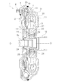
- FIG. 1 is a cross-sectional view of a torque converter including a lockup device according to an embodiment of the present invention.
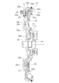
- Sectional drawing which extracts and shows the lockup apparatus of FIG.
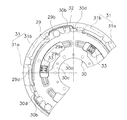
- the partial front view of a lockup apparatus The front view of a retaining plate.
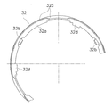
- the front view of a driven plate The front fragmentary view of a support plate.
- FIG. 1 is a partial sectional view of a torque converter 1 in which a lockup device according to an embodiment of the present invention is employed.
- An engine (not shown) is arranged on the left side of FIG. 1, and a transmission (not shown) is arranged on the right side of the figure.
- OO shown in FIG. 1 is a rotation axis of the torque converter and the lockup device.
- the torque converter 1 is a device for transmitting torque from a crankshaft of an engine to an input shaft of a transmission by being connected to a member on the engine side by a flexible plate (not shown).
- the torque converter 1 includes a front cover 2, an impeller 3, a turbine 4, a stator 5, and a lockup device 6.
- the front cover 2 is a disk-shaped member, and a center boss 2a is provided at the inner peripheral end, and an outer peripheral cylindrical portion 2b extending toward the axial transmission side is formed at the outer peripheral portion.
- the center boss 2a is a cylindrical member extending in the axial direction, and is inserted into the center hole of the crankshaft.
- a plurality of bolts 8 are fixed to the outer peripheral side of the front cover 2 at equal intervals in the circumferential direction.
- the outer peripheral portion of the flexible plate is fixed to the front cover 2 by a nut screwed into the bolt 8.
- the impeller 3 mainly includes an impeller shell 10, a plurality of impeller blades 11 fixed inside the impeller shell 10, and an impeller hub 12 fixed to the inner peripheral portion of the impeller shell 10.
- the outer peripheral edge of the impeller shell 10 is welded to the tip of the outer peripheral side cylindrical portion 2 b of the front cover 2.
- the turbine 4 is disposed so as to face the impeller 3 in the axial direction.
- the turbine 4 mainly includes a turbine shell 14, a plurality of turbine blades 15 fixed to the impeller side surface of the turbine shell 14, and a turbine hub 16 fixed to the inner peripheral edge of the turbine shell 14. .
- the turbine shell 14 and the turbine hub 16 are fixed by a plurality of rivets 17.
- a spline that engages with the input shaft of the transmission is formed on the inner peripheral surface of the turbine hub 16.
- the stator 5 is a mechanism for rectifying the flow of hydraulic oil returning from the turbine 4 to the impeller 3, and is disposed between the inner peripheral portion of the impeller 3 and the inner peripheral portion of the turbine 4.
- the stator 5 mainly includes an annular stator shell 20 and a plurality of stator blades 21 provided on the outer peripheral surface of the stator shell 20.
- the stator shell 20 is supported by a cylindrical fixed shaft (not shown) via a one-way clutch 22.
- the fixed shaft extends between the outer peripheral surface of the transmission input shaft and the inner peripheral surface of the impeller hub 12.
- a thrust washer 24 is disposed between the inner periphery of the front cover 2 and the turbine hub 16 in the axial direction.
- Thrust bearings 25 and 26 are disposed between the turbine hub 16 and the inner peripheral portion of the stator 5 and between the stator 5 and the impeller 3 in the axial direction, respectively.
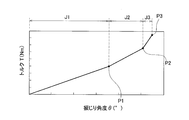
- the lockup device 6 is disposed between the front cover 2 and the turbine 4 and is a mechanism for mechanically connecting the two. As shown in FIGS. 2 and 3, the lockup device 6 includes a piston 28 that constitutes a clutch portion, a retaining plate 29 (input rotating member), a driven plate 30 (output rotating member), and a plurality of outer peripheral sides. A torsion spring 31 (first coil spring), a support plate (meson) 32, and a plurality of inner peripheral torsion springs 33 (second coil springs) are provided. 2 is a diagram showing the lock-up device 6 extracted from FIG. 1, and FIG. 3 is a front view of the lock-up device 6. As shown in FIG. In FIG. 3, some components are not shown and are shown twisted by a predetermined angle (an angle up to a bending point P ⁇ b> 1 in FIG. 7 described later).
- the piston 28 is a member for connecting / disconnecting the clutch, and is a disk-shaped member having a central hole formed therein.
- an inner peripheral cylindrical portion 28a extending toward the axial engine side is formed.
- the inner peripheral cylindrical portion 28a is supported by the engine outer peripheral surface of the turbine hub 16 so as to be movable in the rotational direction and the axial direction.
- An annular seal member 35 is provided on the outer peripheral surface of the turbine hub 16 on the engine side so as to contact the inner peripheral surface of the inner peripheral cylindrical portion 28a.
- a friction coupling portion 28 b is formed on the outer peripheral side of the piston 28.
- the friction coupling portion 28b is an annular portion having a predetermined length in the radial direction, and an annular friction facing 36 is bonded to the surface on the front cover 2 side.
- the clutch portion of the lockup device 6 is configured by the piston 28 and the flat friction surface of the front cover 2.
- the retaining plate 29 is formed in an annular shape and is disposed on the turbine 4 side of the outer peripheral portion of the piston 28. As shown in FIG. 4, the retaining plate 29 includes a fixing portion 29a, a plurality of engaging portions 29b, a plurality of spring accommodating portions 29c, and a plurality of stopper portions 29d.
- (a) is a front view
- (b) is a B arrow view
- (c) is a C arrow view.
- the fixing portion 29 a contacts the side surface of the piston 28 and is fixed to the piston 28 by a rivet 37.
- the engaging portion 29b extends from the fixed portion 29a to the outer peripheral side, and is provided at equal angular intervals in the circumferential direction. As shown in FIG.4 (b), as for the engaging part 29b, a part of outer peripheral edge part (both ends of the circumferential direction) is bend
- the spring accommodating portion 29c is formed in a plurality of extending portions 29e extending from the fixed portion 29a to the inner peripheral side.
- the extending portions 29e are formed at equal angular intervals between the two engaging portions 29b in the circumferential direction.
- the spring accommodating portion 29c is an opening formed by cutting and raising a part of the extension portion 29e toward the turbine side.
- An inner peripheral side torsion spring 33 is accommodated in the spring accommodating portion 29c.
- the stopper portion 29d is formed at the same position as the spring accommodating portion 29c in the circumferential direction by bending a part of the outer peripheral end toward the turbine side.
- FIG. 5 is a front view of the driven plate 30.
- the driven plate 30 is formed in an annular and substantially disk shape, and is disposed on the turbine side of the retaining plate 29.
- the driven plate 30 includes an annular fixed portion 30a formed on the inner peripheral portion, a plurality of engaging portions 30b formed on the outer peripheral portion, and a plurality of spring operating portions 30c formed on the outer peripheral side of the fixed portion 30a.
- a plurality of intermediate stopper portions 30d and a final stopper portion 30e are provided.
- the fixed portion 30a is fixed to the turbine hub 16 by a rivet 17 together with the turbine shell 14, as shown in FIG.
- the plurality of engaging portions 30b are formed on the outermost peripheral side, and a set of two engaging portions 30b are arranged at equiangular intervals in the circumferential direction. Each engaging portion 30b is formed by being bent toward the front cover 2 side.
- the spring operating portion 30c is a plurality of arc-shaped openings extending in the circumferential direction.
- the spring operating portion 30c is formed in a region where the engaging portion 30b is not formed in the circumferential direction.
- a part of the spring accommodating portion 29c of the retaining plate 29 and the inner peripheral side torsion spring 33 can be accommodated in the spring operating portion 30c.
- projecting portions 30f projecting toward the front cover 2 are formed at both ends of the spring operating portion 30c in the circumferential direction.
- the protrusion 30 f can abut on the circumferential end surface of the inner peripheral torsion spring 33.
- the intermediate stopper portion 30d is formed between the circumferential direction of the pair of engaging portions 30b, and is formed by being bent toward the turbine 4 side. Further, the final stopper portion 30e is formed so as to sandwich the pair of engaging portions 30b, and is formed to protrude to the outer peripheral side.
- FIG. 6 is a partial front view of the support plate 32.
- the support plate 32 is formed in an annular shape, and includes a disc portion 32a, a plurality of engaging portions 32b, an outer peripheral support portion 32c, and a plurality of stopper portions 32d.
- the support plate 32 is disposed so as to be relatively rotatable with respect to the retaining plate 29 and the driven plate 30 within a predetermined angle range.
- the disc part 32 a is disposed on the turbine 4 side of the outer peripheral side torsion spring 31, and regulates the axial movement of the outer peripheral side torsion spring 31 together with the piston 28.
- the plurality of engaging portions 32b extend from the disc portion 32a to the inner peripheral side, further extend to the front cover 2 side, and the tips are bent to the outer peripheral side.
- a pair of torsion springs 31 on the outer peripheral side are disposed with the engaging portion 32b interposed therebetween.
- the outer peripheral support portion 32c is formed to extend from the outer peripheral portion of the disc portion 32a to the front cover 2 side, and restricts the movement of the outer peripheral side torsion spring 31 in the radial direction.
- the stopper portion 32d is formed by extending the inner peripheral portion of the disc portion 32a further to the inner peripheral side, and is arranged at a predetermined angle in one direction from the engaging portion 32b.
- each pair of outer peripheral torsion springs 31 includes a low-rigidity spring 31a and a high-rigidity spring 31b having higher rigidity than the low-rigidity spring 31a.
- the opposing end surfaces of the low-rigidity spring 31a and the high-rigidity spring 31b are in contact with the engaging portion 32b, and both springs 31a and 31b act in series. Both the springs 31 a and 31 b have a free length longer than that of the inner torsion spring 33.
- FIG. 7 is a diagram showing torsional characteristics when the torsion springs 31 and 33 are actuated.
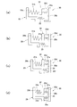
- FIG. 8 is a model diagram when the torsion springs 31 and 33 are operated at each stage of torsional characteristics.
- the outer peripheral torsion spring 31 rotates between the retaining plate 29 and the driven plate 30. Is compressed. In this state (region shown by J1 in FIG. 6 and state shown in FIG. 8A), only the low-rigidity spring 31a is compressed. Depending on the setting of the rigidity of the low-rigidity spring 31a and the high-rigidity spring 31b, the high-rigidity spring 31b may start to compress in the J1 region.
- the low-rigidity and high-rigidity springs 31 a and 31 b are compressed in the rotational direction between the engaging portion 29 b of the retaining plate 29 and the engaging portion 30 b of the driven plate 30.
- the support plate 32 rotates together with the springs 31 a and 31 b and rotates relative to the retaining plate 29 and the driven plate 30.
- the stopper portion 32d of the support plate 32 is brought into contact with the intermediate stopper portion 30d of the driven plate 30 before the low-rigidity spring 31a comes into close contact with the line. For this reason, multistage torsional characteristics can be realized without causing the low-rigidity spring 31a to be in close contact with each other. Therefore, the stress of the low-rigidity spring 31a can be reduced and the durability can be improved.
- the stopper portion 32d of the support plate 32 is brought into contact with the intermediate stopper portion 30d of the driven plate 30 so that the low-rigidity spring 31a is not in close contact with the line.
- the part may be brought into contact with a part of the retaining plate.
- the inner peripheral side torsion springs are arranged on the inner peripheral side of the outer peripheral side torsion springs, but the arrangement of these torsion springs is not limited.
- the first coil spring and the second coil spring may be arranged at the same radial position.
- the stress acting on the torsion spring on the low rigidity side is particularly reduced, and the life can be extended.
Landscapes
- Engineering & Computer Science (AREA)
- General Engineering & Computer Science (AREA)
- Mechanical Engineering (AREA)
- Physics & Mathematics (AREA)
- Acoustics & Sound (AREA)
- Aviation & Aerospace Engineering (AREA)
- Mechanical Operated Clutches (AREA)
Abstract
Description
トルクコンバータ1は、図示しないフレキシブルプレートによってエンジン側の部材に連結され、エンジンのクランクシャフトからトランスミッションの入力シャフトにトルクを伝達するための装置である。トルクコンバータ1は、フロントカバー2と、インペラ3と、タービン4と、ステータ5と、ロックアップ装置6と、から構成されている。
ロックアップ装置6は、フロントカバー2とタービン4との間に配置されており、両者を機械的に連結するための機構である。図2及び図3に示すように、ロックアップ装置6は、クラッチ部を構成するピストン28と、リティニングプレート29(入力回転部材)と、ドリブンプレート30(出力回転部材)と、複数の外周側トーションスプリング31(第1コイルスプリング)と、サポートプレート(中間子)32と、複数の内周側トーションスプリング33(第2コイルスプリング)と、を有している。なお、図2は図1のロックアップ装置6を抽出して示す図であり、図3はロックアップ装置6の正面図である。図3では、一部の構成部材を省略して示しており、かつ所定角度(後述する図7の屈曲点P1までの角度)だけ捩じられた状態を示している。
ピストン28は、クラッチの連結・遮断を行うための部材であり、中心孔が形成された円板状部材である。ピストン28の内周縁には、軸方向エンジン側に延びる内周側筒状部28aが形成されている。内周側筒状部28aはタービンハブ16のエンジン側の外周面によって回転方向及び軸方向に移動可能に支持されている。なお、タービンハブ16のエンジン側の外周面には内周側筒状部28aの内周面に当接する環状のシール部材35が設けられている。
リティニングプレート29は、環状に形成され、ピストン28の外周部のタービン4側に配置されている。リティニングプレート29は、図4に示すように、固定部29aと、複数の係合部29bと、複数のスプリング収容部29cと、複数のストッパ部29dと、を有している。図4において、(a)は正面図であり、(b)はB矢視図、(c)はC矢視図である。
図5はドリブンプレート30の正面図である。ドリブンプレート30は、環状でかつほぼ円板状に形成され、リティニングプレート29のタービン側に配置されている。ドリブンプレート30は、内周部に形成された環状の固定部30aと、外周部に形成された複数の係合部30bと、固定部30aの外周側に形成された複数のスプリング作動部30cと、複数の中間ストッパ部30dと、最終ストッパ部30eを有している。
図6はサポートプレート32の正面部分図である。サポートプレート32は、環状に形成され、円板部32aと、複数の係合部32bと、外周支持部32cと、複数のストッパ部32dと、を有している。サポートプレート32は、リティニングプレート29及びドリブンプレート30に対して所定の角度範囲で相対回転自在に配置されている。
エンジン回転数が低い領域では、ピストン28のフロントカバー2側とタービン4側の油圧差によってピストン28はタービン4側に移動している。このため、摩擦フェーシング36はフロントカバー2から離れ、ロックアップが解除されている。
以上のような本実施形態では、低剛性スプリング31aが線間密着する以前に、サポートプレート32のストッパ部32dをドリブンプレート30の中間ストッパ部30dに当接させている。このため、低剛性スプリング31aを線間密着させることなく多段の捩じり特性を実現することができる。したがって、低剛性スプリング31aの応力を軽減でき、耐久性を向上することができる。
(a)前記実施形態では、サポートプレート32のストッパ部32dをドリブンプレート30の中間ストッパ部30dに当接させて、低剛性スプリング31aが線間密着しないように構成したが、サポートプレート32の一部をリティニングプレートの一部に当接させるようにしてもよい。
6 ロックアップ装置
29 リティニングプレート(入力回転部材)
29d ストッパ部
30 ドリブンプレート(出力回転部材)
30d 中間ストッパ部
30e 最終ストッパ部
31 外周側トーションスプリング(第1コイルスプリング)
31a 低剛性スプリング
31b 高剛性スプリング
32 サポートプレート(中間子)
32d ストッパ部
Claims (6)
- トルクを伝達するとともに捩り振動を吸収・減衰するためのトルクコンバータのロックアップ装置であって、
入力回転部材と、
出力回転部材と、
前記入力回転部材と前記出力回転部材とを回転方向に弾性的に連結する複数対の第1コイルスプリングと、
前記入力回転部材及び前記出力回転部材に対して所定の角度範囲で相対回転自在であり、各対の前記第1コイルスプリングを直列的に作用させるための中間子と、
長さが前記第1コイルスプリングの長さより短く、前記入力回転部材と前記出力回転部材とを回転方向に弾性的に連結する複数の第2コイルスプリングと、
を備え、
前記入力回転部材又は前記出力回転部材に対する前記中間子の相対回転は、前記中間子の一部が前記入力回転部材又は前記出力回転部材に当接することによって規制される、
トルクコンバータのロックアップ装置。 - 各対の前記第1コイルスプリングは、低剛性コイルスプリングと、前記低剛性コイルスプリングより捩じり剛性が高い高剛性コイルスプリングと、からなり、
前記中間子は、前記低剛性コイルスプリングが線間密着する前に前記入力回転部材及び前記出力回転部材に対する相対回転が規制される、
請求項1に記載のトルクコンバータのロックアップ装置。 - 前記高剛性コイルスプリングは、前記入力回転部材及び前記出力回転部材に対する前記中間子の相対回転許容角度よりも広い捩じり角度範囲で作動する、請求項2に記載のトルクコンバータのロックアップ装置。
- 前記第2コイルスプリングは前記高剛性コイルスプリングの作動後に作動を開始する、請求項3に記載のトルクコンバータのロックアップ装置。
- 前記第2コイルスプリングは前記第1コイルスプリングの内周側に配置されている、請求項1から4のいずれかに記載のトルクコンバータのロックアップ装置。
- 前記第2コイルスプリングの圧縮は、前記入力回転部材と前記出力回転部材の一部が当接して両部材の相対回転が規制されることによって規制される、請求項4に記載のトルクコンバータのロックアップ装置。
Priority Applications (3)
| Application Number | Priority Date | Filing Date | Title |
|---|---|---|---|
| DE112014001888.0T DE112014001888T5 (de) | 2013-04-09 | 2014-03-18 | Überbrückungsvorrichtung für einen Drehmomentwandler |
| CN201480016632.5A CN105190102B (zh) | 2013-04-09 | 2014-03-18 | 液力变矩器用的锁定装置 |
| US14/766,297 US9394982B2 (en) | 2013-04-09 | 2014-03-18 | Lock-up device for torque converter |
Applications Claiming Priority (2)
| Application Number | Priority Date | Filing Date | Title |
|---|---|---|---|
| JP2013080957A JP5688113B2 (ja) | 2013-04-09 | 2013-04-09 | トルクコンバータ用のロックアップ装置 |
| JP2013-080957 | 2013-04-09 |
Publications (1)
| Publication Number | Publication Date |
|---|---|
| WO2014167955A1 true WO2014167955A1 (ja) | 2014-10-16 |
Family
ID=51689368
Family Applications (1)
| Application Number | Title | Priority Date | Filing Date |
|---|---|---|---|
| PCT/JP2014/057269 Ceased WO2014167955A1 (ja) | 2013-04-09 | 2014-03-18 | トルクコンバータ用のロックアップ装置 |
Country Status (5)
| Country | Link |
|---|---|
| US (1) | US9394982B2 (ja) |
| JP (1) | JP5688113B2 (ja) |
| CN (1) | CN105190102B (ja) |
| DE (1) | DE112014001888T5 (ja) |
| WO (1) | WO2014167955A1 (ja) |
Cited By (1)
| Publication number | Priority date | Publication date | Assignee | Title |
|---|---|---|---|---|
| JP2016133159A (ja) * | 2015-01-19 | 2016-07-25 | 株式会社エクセディ | トルクコンバータ用のロックアップ装置 |
Families Citing this family (3)
| Publication number | Priority date | Publication date | Assignee | Title |
|---|---|---|---|---|
| JP6714420B2 (ja) * | 2016-04-15 | 2020-06-24 | 株式会社エクセディ | ダンパ装置 |
| JP6828440B2 (ja) * | 2017-01-10 | 2021-02-10 | アイシン精機株式会社 | ダンパ装置 |
| JP7130086B1 (ja) * | 2021-04-27 | 2022-09-02 | ヴァレオ、カペック、カンパニー、リミテッド | ロックアップダンパ |
Citations (4)
| Publication number | Priority date | Publication date | Assignee | Title |
|---|---|---|---|---|
| JP2009156270A (ja) * | 2007-12-25 | 2009-07-16 | Aisin Aw Industries Co Ltd | トルクコンバータのロックアップダンパ装置 |
| JP2009168226A (ja) * | 2008-01-18 | 2009-07-30 | Exedy Corp | ロックアップ装置 |
| JP2011252584A (ja) * | 2010-06-04 | 2011-12-15 | Exedy Corp | トルクコンバータ用のロックアップ装置 |
| JP2012219999A (ja) * | 2011-04-14 | 2012-11-12 | Exedy Corp | トルクコンバータ用のロックアップ装置 |
Family Cites Families (6)
| Publication number | Priority date | Publication date | Assignee | Title |
|---|---|---|---|---|
| US4693348A (en) * | 1985-04-30 | 1987-09-15 | Aisin Warner Kabushiki Kaisha | Direct coupling clutch with an integral damper device for a fluid coupling |
| WO1989002551A1 (fr) * | 1987-09-11 | 1989-03-23 | Kabushiki Kaisha Daikin Seisakusho | Amortisseur a calage pour convertisseurs de couple |
| US7658679B2 (en) * | 2005-09-08 | 2010-02-09 | Luk Lamellen Und Kupplungsbau Beteiligungs Kg | Series-parallel multistage torque converter damper |
| JP4999438B2 (ja) | 2006-12-04 | 2012-08-15 | 株式会社エクセディ | ロックアップ装置およびそれを備えた流体式トルク伝達装置 |
| JP2009250288A (ja) * | 2008-04-02 | 2009-10-29 | Exedy Corp | ロックアップ装置 |
| JP4791582B2 (ja) | 2010-02-26 | 2011-10-12 | 株式会社エクセディ | トルクコンバータ用のロックアップ装置 |
-
2013
- 2013-04-09 JP JP2013080957A patent/JP5688113B2/ja active Active
-
2014
- 2014-03-18 DE DE112014001888.0T patent/DE112014001888T5/de not_active Withdrawn
- 2014-03-18 US US14/766,297 patent/US9394982B2/en active Active
- 2014-03-18 CN CN201480016632.5A patent/CN105190102B/zh active Active
- 2014-03-18 WO PCT/JP2014/057269 patent/WO2014167955A1/ja not_active Ceased
Patent Citations (4)
| Publication number | Priority date | Publication date | Assignee | Title |
|---|---|---|---|---|
| JP2009156270A (ja) * | 2007-12-25 | 2009-07-16 | Aisin Aw Industries Co Ltd | トルクコンバータのロックアップダンパ装置 |
| JP2009168226A (ja) * | 2008-01-18 | 2009-07-30 | Exedy Corp | ロックアップ装置 |
| JP2011252584A (ja) * | 2010-06-04 | 2011-12-15 | Exedy Corp | トルクコンバータ用のロックアップ装置 |
| JP2012219999A (ja) * | 2011-04-14 | 2012-11-12 | Exedy Corp | トルクコンバータ用のロックアップ装置 |
Cited By (4)
| Publication number | Priority date | Publication date | Assignee | Title |
|---|---|---|---|---|
| JP2016133159A (ja) * | 2015-01-19 | 2016-07-25 | 株式会社エクセディ | トルクコンバータ用のロックアップ装置 |
| WO2016117219A1 (ja) * | 2015-01-19 | 2016-07-28 | 株式会社エクセディ | トルクコンバータ用のロックアップ装置 |
| CN107110325A (zh) * | 2015-01-19 | 2017-08-29 | 株式会社艾科赛迪 | 液力变矩器用的锁定装置 |
| US10487908B2 (en) | 2015-01-19 | 2019-11-26 | Exedy Corporation | Lock-up device for torque converter |
Also Published As
| Publication number | Publication date |
|---|---|
| JP2014202328A (ja) | 2014-10-27 |
| DE112014001888T5 (de) | 2015-12-24 |
| CN105190102B (zh) | 2017-08-01 |
| US9394982B2 (en) | 2016-07-19 |
| CN105190102A (zh) | 2015-12-23 |
| JP5688113B2 (ja) | 2015-03-25 |
| US20160017972A1 (en) | 2016-01-21 |
Similar Documents
| Publication | Publication Date | Title |
|---|---|---|
| CN103038544B (zh) | 流体传动装置 | |
| JP4773553B2 (ja) | トルクコンバータ用ロックアップ装置 | |
| JP5852701B2 (ja) | 流体式動力伝達装置 | |
| US20120180473A1 (en) | Hydrodynamic torque converter having a vibration absorber and torsional vibration damper | |
| JP4755277B2 (ja) | トルクコンバータ用ロックアップ装置 | |
| JP6252458B2 (ja) | ダンパ装置 | |
| JP2011122622A (ja) | トルクコンバータ用ロックアップ装置 | |
| US9470290B2 (en) | Torque coupler | |
| JP6182434B2 (ja) | トルクコンバータのロックアップ装置 | |
| WO2014185148A1 (ja) | トルクコンバータのロックアップ装置 | |
| JP4395343B2 (ja) | ロックアップ装置のダンパー機構 | |
| JP5688113B2 (ja) | トルクコンバータ用のロックアップ装置 | |
| JP6714420B2 (ja) | ダンパ装置 | |
| JP6605280B2 (ja) | ダンパ装置 | |
| JP5246877B2 (ja) | ダンパ装置 | |
| JP2019056461A (ja) | ダンパ装置 | |
| JP7599323B2 (ja) | ダンパ装置 | |
| JP2010014206A (ja) | 捩り振動低減装置 | |
| JP2014206244A (ja) | トルクコンバータのロックアップ装置 | |
| JP4522220B2 (ja) | ダンパーディスク組立体 | |
| JP5781134B2 (ja) | 振り子式ダンパ装置及びトルクコンバータのロックアップ装置 | |
| JP5775407B2 (ja) | トルク変動吸収装置 | |
| KR101866937B1 (ko) | 차량용 토크 컨버터 | |
| JP6685770B2 (ja) | トルクコンバータ |
Legal Events
| Date | Code | Title | Description |
|---|---|---|---|
| WWE | Wipo information: entry into national phase |
Ref document number: 201480016632.5 Country of ref document: CN |
|
| 121 | Ep: the epo has been informed by wipo that ep was designated in this application |
Ref document number: 14782157 Country of ref document: EP Kind code of ref document: A1 |
|
| WWE | Wipo information: entry into national phase |
Ref document number: 14766297 Country of ref document: US |
|
| WWE | Wipo information: entry into national phase |
Ref document number: 1120140018880 Country of ref document: DE Ref document number: 112014001888 Country of ref document: DE |
|
| 122 | Ep: pct application non-entry in european phase |
Ref document number: 14782157 Country of ref document: EP Kind code of ref document: A1 |