WO2014167653A1 - 車両用変速機及び制御装置 - Google Patents
車両用変速機及び制御装置 Download PDFInfo
- Publication number
- WO2014167653A1 WO2014167653A1 PCT/JP2013/060746 JP2013060746W WO2014167653A1 WO 2014167653 A1 WO2014167653 A1 WO 2014167653A1 JP 2013060746 W JP2013060746 W JP 2013060746W WO 2014167653 A1 WO2014167653 A1 WO 2014167653A1
- Authority
- WO
- WIPO (PCT)
- Prior art keywords
- power
- engine
- transmission
- rotating machine
- state
- Prior art date
- Legal status (The legal status is an assumption and is not a legal conclusion. Google has not performed a legal analysis and makes no representation as to the accuracy of the status listed.)
- Ceased
Links
Images





Classifications
-
- B—PERFORMING OPERATIONS; TRANSPORTING
- B60—VEHICLES IN GENERAL
- B60W—CONJOINT CONTROL OF VEHICLE SUB-UNITS OF DIFFERENT TYPE OR DIFFERENT FUNCTION; CONTROL SYSTEMS SPECIALLY ADAPTED FOR HYBRID VEHICLES; ROAD VEHICLE DRIVE CONTROL SYSTEMS FOR PURPOSES NOT RELATED TO THE CONTROL OF A PARTICULAR SUB-UNIT
- B60W20/00—Control systems specially adapted for hybrid vehicles
- B60W20/40—Controlling the engagement or disengagement of prime movers, e.g. for transition between prime movers
-
- F—MECHANICAL ENGINEERING; LIGHTING; HEATING; WEAPONS; BLASTING
- F16—ENGINEERING ELEMENTS AND UNITS; GENERAL MEASURES FOR PRODUCING AND MAINTAINING EFFECTIVE FUNCTIONING OF MACHINES OR INSTALLATIONS; THERMAL INSULATION IN GENERAL
- F16H—GEARING
- F16H61/00—Control functions within control units of change-speed- or reversing-gearings for conveying rotary motion ; Control of exclusively fluid gearing, friction gearing, gearings with endless flexible members or other particular types of gearing
- F16H61/02—Control functions within control units of change-speed- or reversing-gearings for conveying rotary motion ; Control of exclusively fluid gearing, friction gearing, gearings with endless flexible members or other particular types of gearing characterised by the signals used
- F16H61/0202—Control functions within control units of change-speed- or reversing-gearings for conveying rotary motion ; Control of exclusively fluid gearing, friction gearing, gearings with endless flexible members or other particular types of gearing characterised by the signals used the signals being electric
- F16H61/0204—Control functions within control units of change-speed- or reversing-gearings for conveying rotary motion ; Control of exclusively fluid gearing, friction gearing, gearings with endless flexible members or other particular types of gearing characterised by the signals used the signals being electric for gearshift control, e.g. control functions for performing shifting or generation of shift signal
-
- B—PERFORMING OPERATIONS; TRANSPORTING
- B60—VEHICLES IN GENERAL
- B60K—ARRANGEMENT OR MOUNTING OF PROPULSION UNITS OR OF TRANSMISSIONS IN VEHICLES; ARRANGEMENT OR MOUNTING OF PLURAL DIVERSE PRIME-MOVERS IN VEHICLES; AUXILIARY DRIVES FOR VEHICLES; INSTRUMENTATION OR DASHBOARDS FOR VEHICLES; ARRANGEMENTS IN CONNECTION WITH COOLING, AIR INTAKE, GAS EXHAUST OR FUEL SUPPLY OF PROPULSION UNITS IN VEHICLES
- B60K6/00—Arrangement or mounting of plural diverse prime-movers for mutual or common propulsion, e.g. hybrid propulsion systems comprising electric motors and internal combustion engines
- B60K6/20—Arrangement or mounting of plural diverse prime-movers for mutual or common propulsion, e.g. hybrid propulsion systems comprising electric motors and internal combustion engines the prime-movers consisting of electric motors and internal combustion engines, e.g. HEVs
- B60K6/22—Arrangement or mounting of plural diverse prime-movers for mutual or common propulsion, e.g. hybrid propulsion systems comprising electric motors and internal combustion engines the prime-movers consisting of electric motors and internal combustion engines, e.g. HEVs characterised by apparatus, components or means specially adapted for HEVs
- B60K6/26—Arrangement or mounting of plural diverse prime-movers for mutual or common propulsion, e.g. hybrid propulsion systems comprising electric motors and internal combustion engines the prime-movers consisting of electric motors and internal combustion engines, e.g. HEVs characterised by apparatus, components or means specially adapted for HEVs characterised by the motors or the generators
-
- B—PERFORMING OPERATIONS; TRANSPORTING
- B60—VEHICLES IN GENERAL
- B60K—ARRANGEMENT OR MOUNTING OF PROPULSION UNITS OR OF TRANSMISSIONS IN VEHICLES; ARRANGEMENT OR MOUNTING OF PLURAL DIVERSE PRIME-MOVERS IN VEHICLES; AUXILIARY DRIVES FOR VEHICLES; INSTRUMENTATION OR DASHBOARDS FOR VEHICLES; ARRANGEMENTS IN CONNECTION WITH COOLING, AIR INTAKE, GAS EXHAUST OR FUEL SUPPLY OF PROPULSION UNITS IN VEHICLES
- B60K6/00—Arrangement or mounting of plural diverse prime-movers for mutual or common propulsion, e.g. hybrid propulsion systems comprising electric motors and internal combustion engines
- B60K6/20—Arrangement or mounting of plural diverse prime-movers for mutual or common propulsion, e.g. hybrid propulsion systems comprising electric motors and internal combustion engines the prime-movers consisting of electric motors and internal combustion engines, e.g. HEVs
- B60K6/22—Arrangement or mounting of plural diverse prime-movers for mutual or common propulsion, e.g. hybrid propulsion systems comprising electric motors and internal combustion engines the prime-movers consisting of electric motors and internal combustion engines, e.g. HEVs characterised by apparatus, components or means specially adapted for HEVs
- B60K6/36—Arrangement or mounting of plural diverse prime-movers for mutual or common propulsion, e.g. hybrid propulsion systems comprising electric motors and internal combustion engines the prime-movers consisting of electric motors and internal combustion engines, e.g. HEVs characterised by apparatus, components or means specially adapted for HEVs characterised by the transmission gearings
-
- B—PERFORMING OPERATIONS; TRANSPORTING
- B60—VEHICLES IN GENERAL
- B60K—ARRANGEMENT OR MOUNTING OF PROPULSION UNITS OR OF TRANSMISSIONS IN VEHICLES; ARRANGEMENT OR MOUNTING OF PLURAL DIVERSE PRIME-MOVERS IN VEHICLES; AUXILIARY DRIVES FOR VEHICLES; INSTRUMENTATION OR DASHBOARDS FOR VEHICLES; ARRANGEMENTS IN CONNECTION WITH COOLING, AIR INTAKE, GAS EXHAUST OR FUEL SUPPLY OF PROPULSION UNITS IN VEHICLES
- B60K6/00—Arrangement or mounting of plural diverse prime-movers for mutual or common propulsion, e.g. hybrid propulsion systems comprising electric motors and internal combustion engines
- B60K6/20—Arrangement or mounting of plural diverse prime-movers for mutual or common propulsion, e.g. hybrid propulsion systems comprising electric motors and internal combustion engines the prime-movers consisting of electric motors and internal combustion engines, e.g. HEVs
- B60K6/22—Arrangement or mounting of plural diverse prime-movers for mutual or common propulsion, e.g. hybrid propulsion systems comprising electric motors and internal combustion engines the prime-movers consisting of electric motors and internal combustion engines, e.g. HEVs characterised by apparatus, components or means specially adapted for HEVs
- B60K6/36—Arrangement or mounting of plural diverse prime-movers for mutual or common propulsion, e.g. hybrid propulsion systems comprising electric motors and internal combustion engines the prime-movers consisting of electric motors and internal combustion engines, e.g. HEVs characterised by apparatus, components or means specially adapted for HEVs characterised by the transmission gearings
- B60K6/365—Arrangement or mounting of plural diverse prime-movers for mutual or common propulsion, e.g. hybrid propulsion systems comprising electric motors and internal combustion engines the prime-movers consisting of electric motors and internal combustion engines, e.g. HEVs characterised by apparatus, components or means specially adapted for HEVs characterised by the transmission gearings with the gears having orbital motion
-
- B—PERFORMING OPERATIONS; TRANSPORTING
- B60—VEHICLES IN GENERAL
- B60K—ARRANGEMENT OR MOUNTING OF PROPULSION UNITS OR OF TRANSMISSIONS IN VEHICLES; ARRANGEMENT OR MOUNTING OF PLURAL DIVERSE PRIME-MOVERS IN VEHICLES; AUXILIARY DRIVES FOR VEHICLES; INSTRUMENTATION OR DASHBOARDS FOR VEHICLES; ARRANGEMENTS IN CONNECTION WITH COOLING, AIR INTAKE, GAS EXHAUST OR FUEL SUPPLY OF PROPULSION UNITS IN VEHICLES
- B60K6/00—Arrangement or mounting of plural diverse prime-movers for mutual or common propulsion, e.g. hybrid propulsion systems comprising electric motors and internal combustion engines
- B60K6/20—Arrangement or mounting of plural diverse prime-movers for mutual or common propulsion, e.g. hybrid propulsion systems comprising electric motors and internal combustion engines the prime-movers consisting of electric motors and internal combustion engines, e.g. HEVs
- B60K6/22—Arrangement or mounting of plural diverse prime-movers for mutual or common propulsion, e.g. hybrid propulsion systems comprising electric motors and internal combustion engines the prime-movers consisting of electric motors and internal combustion engines, e.g. HEVs characterised by apparatus, components or means specially adapted for HEVs
- B60K6/38—Arrangement or mounting of plural diverse prime-movers for mutual or common propulsion, e.g. hybrid propulsion systems comprising electric motors and internal combustion engines the prime-movers consisting of electric motors and internal combustion engines, e.g. HEVs characterised by apparatus, components or means specially adapted for HEVs characterised by the driveline clutches
-
- B—PERFORMING OPERATIONS; TRANSPORTING
- B60—VEHICLES IN GENERAL
- B60K—ARRANGEMENT OR MOUNTING OF PROPULSION UNITS OR OF TRANSMISSIONS IN VEHICLES; ARRANGEMENT OR MOUNTING OF PLURAL DIVERSE PRIME-MOVERS IN VEHICLES; AUXILIARY DRIVES FOR VEHICLES; INSTRUMENTATION OR DASHBOARDS FOR VEHICLES; ARRANGEMENTS IN CONNECTION WITH COOLING, AIR INTAKE, GAS EXHAUST OR FUEL SUPPLY OF PROPULSION UNITS IN VEHICLES
- B60K6/00—Arrangement or mounting of plural diverse prime-movers for mutual or common propulsion, e.g. hybrid propulsion systems comprising electric motors and internal combustion engines
- B60K6/20—Arrangement or mounting of plural diverse prime-movers for mutual or common propulsion, e.g. hybrid propulsion systems comprising electric motors and internal combustion engines the prime-movers consisting of electric motors and internal combustion engines, e.g. HEVs
- B60K6/22—Arrangement or mounting of plural diverse prime-movers for mutual or common propulsion, e.g. hybrid propulsion systems comprising electric motors and internal combustion engines the prime-movers consisting of electric motors and internal combustion engines, e.g. HEVs characterised by apparatus, components or means specially adapted for HEVs
- B60K6/38—Arrangement or mounting of plural diverse prime-movers for mutual or common propulsion, e.g. hybrid propulsion systems comprising electric motors and internal combustion engines the prime-movers consisting of electric motors and internal combustion engines, e.g. HEVs characterised by apparatus, components or means specially adapted for HEVs characterised by the driveline clutches
- B60K6/387—Actuated clutches, i.e. clutches engaged or disengaged by electric, hydraulic or mechanical actuating means
-
- B—PERFORMING OPERATIONS; TRANSPORTING
- B60—VEHICLES IN GENERAL
- B60K—ARRANGEMENT OR MOUNTING OF PROPULSION UNITS OR OF TRANSMISSIONS IN VEHICLES; ARRANGEMENT OR MOUNTING OF PLURAL DIVERSE PRIME-MOVERS IN VEHICLES; AUXILIARY DRIVES FOR VEHICLES; INSTRUMENTATION OR DASHBOARDS FOR VEHICLES; ARRANGEMENTS IN CONNECTION WITH COOLING, AIR INTAKE, GAS EXHAUST OR FUEL SUPPLY OF PROPULSION UNITS IN VEHICLES
- B60K6/00—Arrangement or mounting of plural diverse prime-movers for mutual or common propulsion, e.g. hybrid propulsion systems comprising electric motors and internal combustion engines
- B60K6/20—Arrangement or mounting of plural diverse prime-movers for mutual or common propulsion, e.g. hybrid propulsion systems comprising electric motors and internal combustion engines the prime-movers consisting of electric motors and internal combustion engines, e.g. HEVs
- B60K6/22—Arrangement or mounting of plural diverse prime-movers for mutual or common propulsion, e.g. hybrid propulsion systems comprising electric motors and internal combustion engines the prime-movers consisting of electric motors and internal combustion engines, e.g. HEVs characterised by apparatus, components or means specially adapted for HEVs
- B60K6/40—Arrangement or mounting of plural diverse prime-movers for mutual or common propulsion, e.g. hybrid propulsion systems comprising electric motors and internal combustion engines the prime-movers consisting of electric motors and internal combustion engines, e.g. HEVs characterised by apparatus, components or means specially adapted for HEVs characterised by the assembly or relative disposition of components
-
- B—PERFORMING OPERATIONS; TRANSPORTING
- B60—VEHICLES IN GENERAL
- B60K—ARRANGEMENT OR MOUNTING OF PROPULSION UNITS OR OF TRANSMISSIONS IN VEHICLES; ARRANGEMENT OR MOUNTING OF PLURAL DIVERSE PRIME-MOVERS IN VEHICLES; AUXILIARY DRIVES FOR VEHICLES; INSTRUMENTATION OR DASHBOARDS FOR VEHICLES; ARRANGEMENTS IN CONNECTION WITH COOLING, AIR INTAKE, GAS EXHAUST OR FUEL SUPPLY OF PROPULSION UNITS IN VEHICLES
- B60K6/00—Arrangement or mounting of plural diverse prime-movers for mutual or common propulsion, e.g. hybrid propulsion systems comprising electric motors and internal combustion engines
- B60K6/20—Arrangement or mounting of plural diverse prime-movers for mutual or common propulsion, e.g. hybrid propulsion systems comprising electric motors and internal combustion engines the prime-movers consisting of electric motors and internal combustion engines, e.g. HEVs
- B60K6/42—Arrangement or mounting of plural diverse prime-movers for mutual or common propulsion, e.g. hybrid propulsion systems comprising electric motors and internal combustion engines the prime-movers consisting of electric motors and internal combustion engines, e.g. HEVs characterised by the architecture of the hybrid electric vehicle
- B60K6/48—Parallel type
-
- B—PERFORMING OPERATIONS; TRANSPORTING
- B60—VEHICLES IN GENERAL
- B60K—ARRANGEMENT OR MOUNTING OF PROPULSION UNITS OR OF TRANSMISSIONS IN VEHICLES; ARRANGEMENT OR MOUNTING OF PLURAL DIVERSE PRIME-MOVERS IN VEHICLES; AUXILIARY DRIVES FOR VEHICLES; INSTRUMENTATION OR DASHBOARDS FOR VEHICLES; ARRANGEMENTS IN CONNECTION WITH COOLING, AIR INTAKE, GAS EXHAUST OR FUEL SUPPLY OF PROPULSION UNITS IN VEHICLES
- B60K6/00—Arrangement or mounting of plural diverse prime-movers for mutual or common propulsion, e.g. hybrid propulsion systems comprising electric motors and internal combustion engines
- B60K6/20—Arrangement or mounting of plural diverse prime-movers for mutual or common propulsion, e.g. hybrid propulsion systems comprising electric motors and internal combustion engines the prime-movers consisting of electric motors and internal combustion engines, e.g. HEVs
- B60K6/50—Architecture of the driveline characterised by arrangement or kind of transmission units
- B60K6/54—Transmission for changing ratio
- B60K6/543—Transmission for changing ratio the transmission being a continuously variable transmission
-
- B—PERFORMING OPERATIONS; TRANSPORTING
- B60—VEHICLES IN GENERAL
- B60K—ARRANGEMENT OR MOUNTING OF PROPULSION UNITS OR OF TRANSMISSIONS IN VEHICLES; ARRANGEMENT OR MOUNTING OF PLURAL DIVERSE PRIME-MOVERS IN VEHICLES; AUXILIARY DRIVES FOR VEHICLES; INSTRUMENTATION OR DASHBOARDS FOR VEHICLES; ARRANGEMENTS IN CONNECTION WITH COOLING, AIR INTAKE, GAS EXHAUST OR FUEL SUPPLY OF PROPULSION UNITS IN VEHICLES
- B60K6/00—Arrangement or mounting of plural diverse prime-movers for mutual or common propulsion, e.g. hybrid propulsion systems comprising electric motors and internal combustion engines
- B60K6/20—Arrangement or mounting of plural diverse prime-movers for mutual or common propulsion, e.g. hybrid propulsion systems comprising electric motors and internal combustion engines the prime-movers consisting of electric motors and internal combustion engines, e.g. HEVs
- B60K6/50—Architecture of the driveline characterised by arrangement or kind of transmission units
- B60K6/54—Transmission for changing ratio
- B60K6/547—Transmission for changing ratio the transmission being a stepped gearing
-
- B—PERFORMING OPERATIONS; TRANSPORTING
- B60—VEHICLES IN GENERAL
- B60W—CONJOINT CONTROL OF VEHICLE SUB-UNITS OF DIFFERENT TYPE OR DIFFERENT FUNCTION; CONTROL SYSTEMS SPECIALLY ADAPTED FOR HYBRID VEHICLES; ROAD VEHICLE DRIVE CONTROL SYSTEMS FOR PURPOSES NOT RELATED TO THE CONTROL OF A PARTICULAR SUB-UNIT
- B60W10/00—Conjoint control of vehicle sub-units of different type or different function
- B60W10/04—Conjoint control of vehicle sub-units of different type or different function including control of propulsion units
- B60W10/06—Conjoint control of vehicle sub-units of different type or different function including control of propulsion units including control of combustion engines
-
- B—PERFORMING OPERATIONS; TRANSPORTING
- B60—VEHICLES IN GENERAL
- B60W—CONJOINT CONTROL OF VEHICLE SUB-UNITS OF DIFFERENT TYPE OR DIFFERENT FUNCTION; CONTROL SYSTEMS SPECIALLY ADAPTED FOR HYBRID VEHICLES; ROAD VEHICLE DRIVE CONTROL SYSTEMS FOR PURPOSES NOT RELATED TO THE CONTROL OF A PARTICULAR SUB-UNIT
- B60W10/00—Conjoint control of vehicle sub-units of different type or different function
- B60W10/04—Conjoint control of vehicle sub-units of different type or different function including control of propulsion units
- B60W10/08—Conjoint control of vehicle sub-units of different type or different function including control of propulsion units including control of electric propulsion units, e.g. motors or generators
-
- B—PERFORMING OPERATIONS; TRANSPORTING
- B60—VEHICLES IN GENERAL
- B60W—CONJOINT CONTROL OF VEHICLE SUB-UNITS OF DIFFERENT TYPE OR DIFFERENT FUNCTION; CONTROL SYSTEMS SPECIALLY ADAPTED FOR HYBRID VEHICLES; ROAD VEHICLE DRIVE CONTROL SYSTEMS FOR PURPOSES NOT RELATED TO THE CONTROL OF A PARTICULAR SUB-UNIT
- B60W10/00—Conjoint control of vehicle sub-units of different type or different function
- B60W10/10—Conjoint control of vehicle sub-units of different type or different function including control of change-speed gearings
- B60W10/11—Stepped gearings
- B60W10/113—Stepped gearings with two input flow paths, e.g. double clutch transmission selection of one of the torque flow paths by the corresponding input clutch
-
- B—PERFORMING OPERATIONS; TRANSPORTING
- B60—VEHICLES IN GENERAL
- B60W—CONJOINT CONTROL OF VEHICLE SUB-UNITS OF DIFFERENT TYPE OR DIFFERENT FUNCTION; CONTROL SYSTEMS SPECIALLY ADAPTED FOR HYBRID VEHICLES; ROAD VEHICLE DRIVE CONTROL SYSTEMS FOR PURPOSES NOT RELATED TO THE CONTROL OF A PARTICULAR SUB-UNIT
- B60W20/00—Control systems specially adapted for hybrid vehicles
-
- B—PERFORMING OPERATIONS; TRANSPORTING
- B60—VEHICLES IN GENERAL
- B60W—CONJOINT CONTROL OF VEHICLE SUB-UNITS OF DIFFERENT TYPE OR DIFFERENT FUNCTION; CONTROL SYSTEMS SPECIALLY ADAPTED FOR HYBRID VEHICLES; ROAD VEHICLE DRIVE CONTROL SYSTEMS FOR PURPOSES NOT RELATED TO THE CONTROL OF A PARTICULAR SUB-UNIT
- B60W20/00—Control systems specially adapted for hybrid vehicles
- B60W20/10—Controlling the power contribution of each of the prime movers to meet required power demand
- B60W20/11—Controlling the power contribution of each of the prime movers to meet required power demand using model predictive control [MPC] strategies, i.e. control methods based on models predicting performance
-
- B—PERFORMING OPERATIONS; TRANSPORTING
- B60—VEHICLES IN GENERAL
- B60W—CONJOINT CONTROL OF VEHICLE SUB-UNITS OF DIFFERENT TYPE OR DIFFERENT FUNCTION; CONTROL SYSTEMS SPECIALLY ADAPTED FOR HYBRID VEHICLES; ROAD VEHICLE DRIVE CONTROL SYSTEMS FOR PURPOSES NOT RELATED TO THE CONTROL OF A PARTICULAR SUB-UNIT
- B60W20/00—Control systems specially adapted for hybrid vehicles
- B60W20/10—Controlling the power contribution of each of the prime movers to meet required power demand
- B60W20/13—Controlling the power contribution of each of the prime movers to meet required power demand in order to stay within battery power input or output limits; in order to prevent overcharging or battery depletion
-
- B—PERFORMING OPERATIONS; TRANSPORTING
- B60—VEHICLES IN GENERAL
- B60W—CONJOINT CONTROL OF VEHICLE SUB-UNITS OF DIFFERENT TYPE OR DIFFERENT FUNCTION; CONTROL SYSTEMS SPECIALLY ADAPTED FOR HYBRID VEHICLES; ROAD VEHICLE DRIVE CONTROL SYSTEMS FOR PURPOSES NOT RELATED TO THE CONTROL OF A PARTICULAR SUB-UNIT
- B60W20/00—Control systems specially adapted for hybrid vehicles
- B60W20/30—Control strategies involving selection of transmission gear ratio
-
- F—MECHANICAL ENGINEERING; LIGHTING; HEATING; WEAPONS; BLASTING
- F16—ENGINEERING ELEMENTS AND UNITS; GENERAL MEASURES FOR PRODUCING AND MAINTAINING EFFECTIVE FUNCTIONING OF MACHINES OR INSTALLATIONS; THERMAL INSULATION IN GENERAL
- F16H—GEARING
- F16H61/00—Control functions within control units of change-speed- or reversing-gearings for conveying rotary motion ; Control of exclusively fluid gearing, friction gearing, gearings with endless flexible members or other particular types of gearing
- F16H61/68—Control functions within control units of change-speed- or reversing-gearings for conveying rotary motion ; Control of exclusively fluid gearing, friction gearing, gearings with endless flexible members or other particular types of gearing specially adapted for stepped gearings
- F16H61/684—Control functions within control units of change-speed- or reversing-gearings for conveying rotary motion ; Control of exclusively fluid gearing, friction gearing, gearings with endless flexible members or other particular types of gearing specially adapted for stepped gearings without interruption of drive
- F16H61/688—Control functions within control units of change-speed- or reversing-gearings for conveying rotary motion ; Control of exclusively fluid gearing, friction gearing, gearings with endless flexible members or other particular types of gearing specially adapted for stepped gearings without interruption of drive with two inputs, e.g. selection of one of two torque-flow paths by clutches
-
- B—PERFORMING OPERATIONS; TRANSPORTING
- B60—VEHICLES IN GENERAL
- B60K—ARRANGEMENT OR MOUNTING OF PROPULSION UNITS OR OF TRANSMISSIONS IN VEHICLES; ARRANGEMENT OR MOUNTING OF PLURAL DIVERSE PRIME-MOVERS IN VEHICLES; AUXILIARY DRIVES FOR VEHICLES; INSTRUMENTATION OR DASHBOARDS FOR VEHICLES; ARRANGEMENTS IN CONNECTION WITH COOLING, AIR INTAKE, GAS EXHAUST OR FUEL SUPPLY OF PROPULSION UNITS IN VEHICLES
- B60K6/00—Arrangement or mounting of plural diverse prime-movers for mutual or common propulsion, e.g. hybrid propulsion systems comprising electric motors and internal combustion engines
- B60K6/20—Arrangement or mounting of plural diverse prime-movers for mutual or common propulsion, e.g. hybrid propulsion systems comprising electric motors and internal combustion engines the prime-movers consisting of electric motors and internal combustion engines, e.g. HEVs
- B60K6/42—Arrangement or mounting of plural diverse prime-movers for mutual or common propulsion, e.g. hybrid propulsion systems comprising electric motors and internal combustion engines the prime-movers consisting of electric motors and internal combustion engines, e.g. HEVs characterised by the architecture of the hybrid electric vehicle
- B60K6/48—Parallel type
- B60K2006/4816—Electric machine connected or connectable to gearbox internal shaft
-
- B—PERFORMING OPERATIONS; TRANSPORTING
- B60—VEHICLES IN GENERAL
- B60W—CONJOINT CONTROL OF VEHICLE SUB-UNITS OF DIFFERENT TYPE OR DIFFERENT FUNCTION; CONTROL SYSTEMS SPECIALLY ADAPTED FOR HYBRID VEHICLES; ROAD VEHICLE DRIVE CONTROL SYSTEMS FOR PURPOSES NOT RELATED TO THE CONTROL OF A PARTICULAR SUB-UNIT
- B60W2510/00—Input parameters relating to a particular sub-units
- B60W2510/24—Energy storage means
- B60W2510/242—Energy storage means for electrical energy
- B60W2510/244—Charge state
-
- B—PERFORMING OPERATIONS; TRANSPORTING
- B60—VEHICLES IN GENERAL
- B60W—CONJOINT CONTROL OF VEHICLE SUB-UNITS OF DIFFERENT TYPE OR DIFFERENT FUNCTION; CONTROL SYSTEMS SPECIALLY ADAPTED FOR HYBRID VEHICLES; ROAD VEHICLE DRIVE CONTROL SYSTEMS FOR PURPOSES NOT RELATED TO THE CONTROL OF A PARTICULAR SUB-UNIT
- B60W2710/00—Output or target parameters relating to a particular sub-units
- B60W2710/02—Clutches
- B60W2710/021—Clutch engagement state
-
- B—PERFORMING OPERATIONS; TRANSPORTING
- B60—VEHICLES IN GENERAL
- B60W—CONJOINT CONTROL OF VEHICLE SUB-UNITS OF DIFFERENT TYPE OR DIFFERENT FUNCTION; CONTROL SYSTEMS SPECIALLY ADAPTED FOR HYBRID VEHICLES; ROAD VEHICLE DRIVE CONTROL SYSTEMS FOR PURPOSES NOT RELATED TO THE CONTROL OF A PARTICULAR SUB-UNIT
- B60W2710/00—Output or target parameters relating to a particular sub-units
- B60W2710/06—Combustion engines, Gas turbines
- B60W2710/0666—Engine torque
-
- B—PERFORMING OPERATIONS; TRANSPORTING
- B60—VEHICLES IN GENERAL
- B60W—CONJOINT CONTROL OF VEHICLE SUB-UNITS OF DIFFERENT TYPE OR DIFFERENT FUNCTION; CONTROL SYSTEMS SPECIALLY ADAPTED FOR HYBRID VEHICLES; ROAD VEHICLE DRIVE CONTROL SYSTEMS FOR PURPOSES NOT RELATED TO THE CONTROL OF A PARTICULAR SUB-UNIT
- B60W2710/00—Output or target parameters relating to a particular sub-units
- B60W2710/08—Electric propulsion units
- B60W2710/086—Power
-
- Y—GENERAL TAGGING OF NEW TECHNOLOGICAL DEVELOPMENTS; GENERAL TAGGING OF CROSS-SECTIONAL TECHNOLOGIES SPANNING OVER SEVERAL SECTIONS OF THE IPC; TECHNICAL SUBJECTS COVERED BY FORMER USPC CROSS-REFERENCE ART COLLECTIONS [XRACs] AND DIGESTS
- Y02—TECHNOLOGIES OR APPLICATIONS FOR MITIGATION OR ADAPTATION AGAINST CLIMATE CHANGE
- Y02T—CLIMATE CHANGE MITIGATION TECHNOLOGIES RELATED TO TRANSPORTATION
- Y02T10/00—Road transport of goods or passengers
- Y02T10/10—Internal combustion engine [ICE] based vehicles
- Y02T10/40—Engine management systems
-
- Y—GENERAL TAGGING OF NEW TECHNOLOGICAL DEVELOPMENTS; GENERAL TAGGING OF CROSS-SECTIONAL TECHNOLOGIES SPANNING OVER SEVERAL SECTIONS OF THE IPC; TECHNICAL SUBJECTS COVERED BY FORMER USPC CROSS-REFERENCE ART COLLECTIONS [XRACs] AND DIGESTS
- Y02—TECHNOLOGIES OR APPLICATIONS FOR MITIGATION OR ADAPTATION AGAINST CLIMATE CHANGE
- Y02T—CLIMATE CHANGE MITIGATION TECHNOLOGIES RELATED TO TRANSPORTATION
- Y02T10/00—Road transport of goods or passengers
- Y02T10/60—Other road transportation technologies with climate change mitigation effect
- Y02T10/62—Hybrid vehicles
-
- Y—GENERAL TAGGING OF NEW TECHNOLOGICAL DEVELOPMENTS; GENERAL TAGGING OF CROSS-SECTIONAL TECHNOLOGIES SPANNING OVER SEVERAL SECTIONS OF THE IPC; TECHNICAL SUBJECTS COVERED BY FORMER USPC CROSS-REFERENCE ART COLLECTIONS [XRACs] AND DIGESTS
- Y02—TECHNOLOGIES OR APPLICATIONS FOR MITIGATION OR ADAPTATION AGAINST CLIMATE CHANGE
- Y02T—CLIMATE CHANGE MITIGATION TECHNOLOGIES RELATED TO TRANSPORTATION
- Y02T10/00—Road transport of goods or passengers
- Y02T10/60—Other road transportation technologies with climate change mitigation effect
- Y02T10/72—Electric energy management in electromobility
-
- Y—GENERAL TAGGING OF NEW TECHNOLOGICAL DEVELOPMENTS; GENERAL TAGGING OF CROSS-SECTIONAL TECHNOLOGIES SPANNING OVER SEVERAL SECTIONS OF THE IPC; TECHNICAL SUBJECTS COVERED BY FORMER USPC CROSS-REFERENCE ART COLLECTIONS [XRACs] AND DIGESTS
- Y10—TECHNICAL SUBJECTS COVERED BY FORMER USPC
- Y10S—TECHNICAL SUBJECTS COVERED BY FORMER USPC CROSS-REFERENCE ART COLLECTIONS [XRACs] AND DIGESTS
- Y10S903/00—Hybrid electric vehicles, HEVS
- Y10S903/902—Prime movers comprising electrical and internal combustion motors
- Y10S903/903—Prime movers comprising electrical and internal combustion motors having energy storing means, e.g. battery, capacitor
- Y10S903/93—Conjoint control of different elements
-
- Y—GENERAL TAGGING OF NEW TECHNOLOGICAL DEVELOPMENTS; GENERAL TAGGING OF CROSS-SECTIONAL TECHNOLOGIES SPANNING OVER SEVERAL SECTIONS OF THE IPC; TECHNICAL SUBJECTS COVERED BY FORMER USPC CROSS-REFERENCE ART COLLECTIONS [XRACs] AND DIGESTS
- Y10—TECHNICAL SUBJECTS COVERED BY FORMER USPC
- Y10S—TECHNICAL SUBJECTS COVERED BY FORMER USPC CROSS-REFERENCE ART COLLECTIONS [XRACs] AND DIGESTS
- Y10S903/00—Hybrid electric vehicles, HEVS
- Y10S903/902—Prime movers comprising electrical and internal combustion motors
- Y10S903/903—Prime movers comprising electrical and internal combustion motors having energy storing means, e.g. battery, capacitor
- Y10S903/946—Characterized by control of driveline clutch
Definitions
- the present invention relates to a vehicle transmission and a control device.
- Patent Document 1 discloses that the rotation of an engine is transmitted to a transmission gear via either the first clutch shaft or the second clutch shaft while the vehicle is running.
- a vehicle power transmission system is disclosed.
- a motor generator is driven to generate electric power using a rotational speed that is a difference between an input rotational speed of a transmission gear used for traveling and a transmission gear input rotational speed other than traveling.
- This vehicle power transmission system uses, for example, a planetary gear and a coupling gear to extract the difference between the input rotation speed of the transmission gear used for traveling and the transmission gear input rotation speed other than that for traveling, and Connect to a fixed motor generator.
- the present invention has been made in view of the above circumstances, and an object thereof is to provide a vehicle transmission and a control device that can improve fuel efficiency.
- a vehicle transmission can connect and disconnect power transmission between an engine that generates rotational power for running a vehicle and a first input shaft of a first gear group.
- a transmission mechanism having a first engagement device, a second engagement device capable of connecting / disconnecting power transmission between the engine and the second input shaft of the second gear group, and a rotating shaft of the rotating machine And a differential mechanism that connects the first input shaft and the second input shaft so as to be differentially rotatable, and disconnects power transmission between the engine and the first engagement device and the second engagement device.
- a third engagement device that can be contacted, and the engine, the first engagement device, the second engagement device, the third engagement device, and a control device that controls the rotating machine,
- the control device controls the third engaging device and the rotating machine to release the third engaging device and output the rotating machine.
- Characterized in that the rotational power is capable of executing control for running the vehicle.
- the control device controls the engine and the rotating machine based on a power storage state of a power storage device capable of storing the electric power generated by the rotating machine, and the power storage
- the amount of electricity stored in the device is relatively large, the output of the engine is relatively lowered compared to the case where the amount of electricity stored in the electricity storage device is relatively small, and the rotational power output by the rotating machine Control for running the vehicle can be executed.
- the control device controls the first engagement device, the second engagement device, and the rotating machine, and transmits rotational power from the engine to the first gear group.
- a stepped shift state in which a shift can be performed by any one of the second shift stage groups and output from an output shaft, and rotational power from the engine is transmitted to the first shift stage group, and Shifting to a continuously variable transmission state in which the gear can be output from the output shaft by changing at a gear ratio between the gear ratios of each gear stage constituting the second gear group, and the gear ratio can be changed continuously.
- the gear ratio can be changed by controlling the amount
- the control device when the control device causes the third engagement device to be in a disengaged state and causes the vehicle to travel by rotational power output from the rotating machine, the first engagement device,
- the second engagement device may be controlled to bring the first engagement device and the second engagement device into an engaged state.
- the control device determines that the vehicle is in a steady running state when a change amount of a parameter representing the running state of the vehicle is less than a preset steady state determination specified value.
- the steady-state determination specified value is relatively increased, and the amount of power stored in the power storage device is relatively The steady-state determination prescribed value can be made relatively small when the number is small.
- the control device controls the engine and the rotating machine based on a power storage state of a power storage device capable of storing the electric power generated by the rotating machine, and the power storage Control that relatively reduces the amount of power generated by the rotating machine when the amount of electricity stored in the device is relatively large, and relatively increases the amount of power generated by the rotating machine when the amount of electricity stored in the power storage device is relatively small Can be executed.
- the control device has a power storage amount of a power storage device capable of storing the electric power generated by the rotating machine in a state where the vehicle is driven by the rotational power output from the rotating machine. Power that is generated by the engine by relatively increasing the output of the engine when the stored amount of the power storage device is less than a preset allowable lower limit as compared to the case where the amount of power stored in the power storage device is greater than the allowable lower limit.
- a preset allowable lower limit as compared to the case where the amount of power stored in the power storage device is greater than the allowable lower limit.
- the control device controls the rotating machine when the vehicle is decelerating and generates electric power with the rotating machine by the rotational power transmitted from the driving wheel side of the vehicle to the rotating machine.
- the control for storing power in the power storage device can be executed.
- a control device is capable of connecting / disconnecting power transmission between an engine that generates rotational power for running a vehicle and a first input shaft of a first gear group.
- a third engagement device that controls the third engagement device and the rotating machine to bring the third engagement device into a released state and to rotate the third engagement device.
- the vehicle can be controlled to run by the rotational power output from the machine.
- the vehicle transmission and the control device according to the present invention have an effect that the fuel efficiency can be improved.
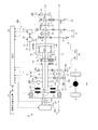
- a transmission 1 as a vehicle transmission according to the present embodiment is applied to a power train 3 mounted on a vehicle 2 as shown in FIG.
- the transmission 1 typically includes a rotating machine 30 via a differential mechanism 20 on two input shafts (first input shaft 13 and second input shaft 14) of a transmission mechanism 10 of a DCT (Dual Clutch Transmission) type.
- the rotating machine 30 controls the differential rotation of both shafts.
- the transmission 1 enables a continuously variable transmission by controlling the ratio of power passing through both shafts, for example.
- the transmission 1 uses, for example, a state where gear stages arranged on both shafts are used as a stepped transmission, and a differential rotation of the differential mechanism 20 is controlled by a rotary machine 30 as a continuously variable transmission.
- the power train 3 of the vehicle 2 to which the transmission 1 is applied includes an engine 4 that generates rotational power for driving the vehicle 2, and power that can transmit the rotational power generated by the engine 4 from the engine 4 to the drive wheels 6.
- a transmission device (transmission) 5 and the like are included.
- the engine 4 is typically a heat engine such as an engine (internal combustion engine) that converts fuel energy into mechanical work by burning the fuel in a combustion chamber and outputs it as power.
- the engine 4 can switch between an operating state and a non-operating state regardless of whether the vehicle 2 is stopped or traveling.
- the operating state of the engine 4 is a state in which power to be applied to the engine output shaft 4a is generated, and a state in which heat energy generated by burning fuel in the combustion chamber is output in the form of mechanical energy such as torque. It is.
- the non-operating state of the engine 4 is a state in which the generation of power is stopped, the fuel supply to the combustion chamber is cut (fuel cut), and the mechanical energy such as torque is not burned in the combustion chamber. Is not output.
- the power transmission device 5 includes a damper 7, a transmission 1, a differential gear 8, and the like. The power transmission device 5 transmits the power generated by the engine 4 to the damper 7 and transmits the rotational power transmitted to the damper 7 to the transmission 1.
- the power transmission device 5 can transmit the rotational power from the engine 4 to the drive wheels 6 of the vehicle 2 by shifting the rotational power from the transmission 1.
- the engine 4, the transmission 1, and the like are controlled by the ECU 50. Therefore, when the engine output shaft 4a of the engine 4 is rotationally driven, the vehicle 2 is input to the transmission 1 through the damper 7 and the like, and is then shifted to the driving wheels 6 through the differential gear 8 and the like. Is done. Thereby, the vehicle 2 can move forward or backward as each drive wheel 6 rotates.
- the transmission 1 of this embodiment is provided in the transmission path of the motive power from the engine 4 to the drive wheel 6, and can change and output the rotational power transmitted from the engine 4 to the drive wheel 6.
- the transmission 1 includes a dual clutch transmission mechanism 10 including a first engagement device C1 and a second engagement device C2, a differential mechanism 20, a rotating machine 30, a power storage device 40, a first 3 engagement device C0 and ECU50 as a control apparatus are provided.
- the speed change mechanism 10 includes an odd speed stage group 11 as a first speed stage group, an even speed stage group 12 as a second speed stage group, a first input shaft 13, a second input shaft 14, an output shaft 15, and a first engagement. It has a combination device C1, a second engagement device C2, and the like.
- the speed change mechanism 10 transmits the rotational power input from the engine 4 to the first input shaft 13 or the second input shaft 14 via the damper 7 or the like in either the odd speed stage group 11 or the even speed stage group 12.
- the gear can be shifted by one gear and output from the output shaft 15 to the drive wheel 6 side.
- the even-numbered speed group 12 constitutes an even-numbered speed shift section (second shift section) 10B.
- the even-numbered speed changing part 10 ⁇ / b> B is further configured to include a switching part 68 and the like.
- the shift stages of the odd-numbered shift stage group 11 and the even-numbered shift stage group 12 are, in order from the larger gear ratio, the first speed shift stage 61, the second speed shift stage 62, the third speed shift stage 63, the fourth speed.
- the gear stage 64 is set.
- the first input shaft 13 is an input rotating member that constitutes the input shaft of the odd-numbered speed group 11 and that receives rotational power from the engine 4 side in the transmission 1.
- the second input shaft 14 constitutes an input shaft of the even-numbered speed stage group 12 and is an input rotating member to which rotational power from the engine 4 side is input in the transmission 1.
- the first input shaft 13 is formed in a cylindrical shape.
- the second input shaft 14 is formed in a cylindrical shape, and the first input shaft 13 is inserted on the inner peripheral side.
- the first input shaft 13 and the second input shaft 14 are supported so as to be rotatable with respect to a case or the like via a bearing.
- the first input shaft 13 and the second input shaft 14 are supported so as to be rotatable about the rotation axis X1 when the power from the engine 4 is transmitted.
- the rotation axis X1 coincides with the rotation center of the engine output shaft 4a of the engine 4. That is, the engine output shaft 4a, the first input shaft 13, and the second input shaft 14 are arranged coaxially with respect to the rotation axis X1.
- the first input shaft 13 is provided with a first engagement device C1 at the end on the engine 4 side.
- the first input shaft 13 protrudes so that the end opposite to the engine 4, that is, the end opposite to the first engagement device C ⁇ b> 1 is exposed from the second input shaft 14.
- the first input shaft 13 includes a first engagement device C1, a differential mechanism 20, a drive gear 61a, a switching unit 66, a drive gear 63a, a switching unit 67, and a drive gear 65a in order from the engine 4 side.
- the first input shaft 13 is provided with a differential mechanism 20, a drive gear 61a, a switching unit 66, a drive gear 63a, a switching unit 67, and a drive gear 65a in a portion exposed from the second input shaft 14.
- the second input shaft 14 is provided with a second engagement device C2 at the end on the engine 4 side.
- the end of the second input shaft 14 opposite to the engine 4, that is, the end opposite to the second engagement device C ⁇ b> 2 is connected to the differential mechanism 20 via the transmission unit 70.
- the second input shaft 14 is provided with a second engagement device C2, a drive gear 64a, a drive gear 62a, and a gear 71 in order from the engine 4 side.
- the output shaft 15 is an output rotating member that outputs rotational power to the drive wheel 6 side in the transmission 1.
- the output shaft 15 is rotatably supported by a casing or the like via a bearing.
- the output shaft 15 receives power from the engine 4 and is supported rotatably about a rotation axis X2 parallel to the rotation axis X1.
- the output shaft 15 functions as a common output member for the odd speed transmission unit 10A and the even speed transmission unit 10B.
- the output shaft 15 is connected to the drive wheels 6 through the drive gear 16, the driven gear 17, the differential gear 8, and the like so as to be able to transmit power.
- the output shaft 15 has a drive gear 16 coupled to the end on the engine 4 side so as to be integrally rotatable, and a driven gear 65b is coupled to the other end so as to be integrally rotatable.
- the output shaft 15 includes a drive gear 16, a driven gear 64b, a switching unit 68, a driven gear 62b, a driven gear 61b, a driven gear 63b, and a driven gear 65b in order from the engine 4 side.
- the drive gears 61a and 63a are supported by the first input shaft 13 through a bush or the like so as to be relatively rotatable, and the driven gears 61b and 63b can be integrally rotated by the output shaft 15.
- the drive gear 61a and the driven gear 61b are a gear pair of the first speed shift stage 61 that mesh with each other.
- the drive gear 63a and the driven gear 63b are a gear pair of the third speed gear stage 63 that meshes with each other.
- the drive gear 65a is supported by the first input shaft 13 via a bush or the like so as to be relatively rotatable, and the driven gear 65b is coupled to the output shaft 15 so as to be integrally rotatable.
- the drive gear 65a and the driven gear 65b are a pair of gears of the reverse stage 65 that mesh with each other.
- the drive gears 62a and 64a are coupled to the second input shaft 14 so as to be integrally rotatable, and the driven gears 62b and 64b are rotatable relative to the output shaft 15 via bushes or the like. Supported.
- the drive gear 62a and the driven gear 62b are a gear pair of the second speed shift stage 62 that meshes with each other.
- the drive gear 64a and the driven gear 64b are a gear pair of the fourth speed gear stage 64 that meshes with each other.
- the speed change mechanism 10 has an even-numbered speed change part 10B on the engine 4 side and an odd-numbered speed change part 10A on the opposite side with respect to the differential mechanism 20 arranged coaxially with the rotation axis X1. Is placed.
- the switching units 66, 67, and 68 that constitute the odd-numbered gear shifting unit 10A and the even-numbered gear shifting unit 10B are each configured to include a synchronous meshing mechanism and the like, and include a first speed gear 61, a second speed gear 62, and a third gear.
- the engagement / release state of the speed gear stage 63, the fourth speed gear stage 64, and the reverse stage 65 is switched.
- the switching unit 66 selectively couples one of the drive gear 61 a and the drive gear 63 a to the first input shaft 13.
- the switching portion 67 is configured to couple the drive gear 65a to the first input shaft 13 when the engaging member is positioned on the drive gear 65a side.
- the odd-stage transmission unit 10A releases the coupling between all the drive gears 61a, 63a, and 65a and the first input shaft 13, and the drive gear 61a, 63a, and 65a are all idle.
- the odd speed transmission unit 10 ⁇ / b> A can block power transmission between the first input shaft 13 and the output shaft 15.
- the switching unit 68 selectively couples one of the driven gear 62 b and the driven gear 64 b to the output shaft 15.
- the even-numbered transmission unit 10B releases the coupling between all the driven gears 62b and 64b and the output shaft 15, and all the driven gears 62b and 64b are in an idling state. As a result, the even-numbered transmission 10B can block the transmission of power between the second input shaft 14 and the output shaft 15.
- an automatic clutch device can be used, but not limited thereto, for example, a dog clutch type engagement device or the like may be used.
- the first engagement device C1 is connected to the first input shaft 13 and the engine-side engagement member Ca connected to the engine output shaft 4a via the damper 7, a third engagement device C0 described later, and the like.
- a transmission-side engagement member C1b that is connected.
- the second engagement device C2 includes an engine-side engagement member Ca that is also used as the first engagement device C1 and a transmission-side engagement member C2b that is connected to the second input shaft 14.
- the first engagement device C1 and the second engagement device C2 can be switched to an engaged state or a released state by an actuator that is operated by hydraulic pressure or the like.
- the first engagement device C1 and the second engagement device C2 can be controlled to a fully engaged state, a semi-engaged state, or a released state according to the supplied hydraulic pressure.
- the differential mechanism 20 connects the rotating shaft 31, the first input shaft 13, and the second input shaft 14 of the rotating machine 30 so as to be differentially rotatable.
- the differential mechanism 20 of the present embodiment is described as being configured by a so-called differential gear, the present invention is not limited thereto, and for example, a planetary gear mechanism or the like may be used.
- the rotation center of each rotary element that can be differentially rotated is arranged coaxially with the rotation axis X1.
- Each rotating element is rotatable about the rotation axis X ⁇ b> 1 as power is transmitted.
- the differential mechanism 20 is configured to include a first sun gear 20S1, a second sun gear 20S2, and a carrier 20C as a plurality of rotational elements capable of differential rotation.
- the first sun gear 20S1 and the second sun gear 20S2 are external gears.
- the carrier 20C holds a plurality of pinion gears 20P meshing with both the first sun gear 20S1 and the second sun gear 20S2 so that they can rotate and revolve.
- the first sun gear 20S1 is connected to the first input shaft 13, the second sun gear 20S2 is connected to the second input shaft 14, and the carrier 20C is connected to the rotating shaft 31. It has become an element.
- the first sun gear 20S1 is formed in a disc shape and is coupled to the first input shaft 13 so as to be integrally rotatable.
- the second sun gear 20 ⁇ / b> S ⁇ b> 2 is formed in an annular shape, and the second input shaft 14 is connected via the transmission unit 70.
- the transmission unit 70 includes a gear 71, a gear 72, a chain transmission mechanism 73, a transmission shaft 74, and the like.
- the gear 71 is coupled to the end of the second input shaft 14 opposite to the end on the second engagement device C2 side so as to be integrally rotatable.
- the gear 72 meshes with the gear 71.
- the chain transmission mechanism 73 transmits power between the gear 72 and the transmission shaft 74 via a chain or the like.
- Transmission shaft 74 is coupled to second sun gear 20S2 so as to be integrally rotatable.
- the transmission part 70 can transmit motive power mutually between the 2nd input shaft 14 and 2nd sun gear 20S2.
- the transmission unit 70 transmits power by reversing the rotation direction about the rotation axis X1 between the second input shaft 14 and the second sun gear 20S2.
- the carrier 20C is formed in an annular plate shape, and supports the pinion gear 20P, which is an external gear, on the pinion shaft so as to be able to rotate and revolve.
- the rotating shaft 31 of the rotating machine 30 is connected to the carrier 20C through the gear 32, the gear 33, and the like.
- the gear 32 is coupled to the carrier 20C so as to be integrally rotatable.
- the gear 33 is coupled to the rotary shaft 31 so as to be integrally rotatable, and meshes with the gear 32.
- the rotating machine 30 is a rotating electrical machine having a function as a motor (electric motor) and a function as a generator.
- the rotating machine 30 includes a power running function that converts electric power supplied from a power storage device 40 such as a battery via an inverter into mechanical power, and a power storage device that converts input mechanical power into electric power via the inverter. Combined with the regenerative function of charging 40.
- the electric power generated by the rotating machine 30 can be stored in the power storage device 40.
- an AC synchronous motor generator can be used as the rotating machine 30, for example, an AC synchronous motor generator can be used.
- the power storage device 40 can store the electric power generated by the rotating machine 30.
- the rotating machine 30 consumes electric power during power running, outputs torque, and can rotate the rotating shaft 31 with the output torque.
- the rotating machine 30 can be rotationally driven by the torque transmitted to the rotating shaft 31 during regeneration to generate electric power, and load torque (reaction torque) corresponding to the power generation load can be applied to the rotating shaft 31.
- the third engagement device C0 is provided between the engine 4 and the first engagement device C1 and the second engagement device C2, and between the engine 4 and the first engagement device C1 and the second engagement device C2.
- the power transmission can be connected and disconnected.
- the third engagement device C0 is provided between the engine 4 and the damper 7. That is, the power transmission device 5 of the present embodiment is arranged in the order of the third engagement device C0, the damper 7, the first engagement device C1, and the second engagement device C2 in order from the engine 4 side with respect to the power transmission path. It has become.
- the third engagement device C0 includes an engaged state in which the engine output shaft 4a of the engine 4 and the damper input shaft 7a of the damper 7 are engaged so as to be able to transmit power, and a released state in which the engagement is released and power transmission is interrupted. Can be switched to. As a result, the third engagement device C0 enables power transmission between the engine 4 and the first engagement device C1 and the second engagement device C2 in the engaged state, and the engine 4 and the first engagement in the released state. Power transmission between the combined device C1 and the second engagement device C2 can be interrupted.
- an automatic clutch device can be used, but not limited thereto, for example, a dog clutch type engagement device or the like may be used.
- the third engagement device C0 includes an engine side engagement member C0a connected to the engine output shaft 4a and a damper side engagement member C0b connected to the damper input shaft 7a.
- the third engagement device C0 can be switched to an engaged state or a released state by an actuator that is operated by hydraulic pressure or the like.
- the third engagement device C0 can be controlled to a fully engaged state, a semi-engaged state, or a released state according to the supplied hydraulic pressure.
- the transmission 1 of this embodiment includes, for example, a vehicle state detection device 51 that detects the state of the vehicle 2 on which the transmission 1 is mounted, as various sensors and detectors.
- the vehicle state detection device 51 includes, for example, a vehicle speed sensor, an accelerator opening sensor, a throttle opening sensor, an engine speed sensor, a first input shaft speed sensor, a second input shaft speed sensor, an output shaft speed sensor, a rotation It may include at least one of a shaft rotational speed sensor, a charge state detector, and the like, but is not limited thereto.
- the vehicle speed sensor detects the vehicle speed of the vehicle 2.
- the accelerator opening sensor detects an accelerator opening corresponding to an operation amount (accelerator operation amount, acceleration request operation amount) of the accelerator pedal of the vehicle 2 by the driver.
- the rotation shaft rotation speed sensor detects the rotation speed of the rotation shaft 31 of the rotating machine 30 (hereinafter sometimes referred to as “rotating machine rotation speed”).
- the state of charge detector detects a state of charge (SOC) according to the amount of charge (charge amount) of the power storage device 40 and the like.
- SOC state of charge
- the power storage state SOC means that the power storage amount of the power storage device 40 increases as the power storage state SOC increases.
- the ECU 50 controls the throttle device of the engine 4 based on, for example, the accelerator opening, the vehicle speed, etc., adjusts the throttle opening of the intake passage, adjusts the intake air amount, and responds to the change to the fuel injection amount. And the output of the engine 4 is controlled by adjusting the amount of the air-fuel mixture charged in the combustion chamber. Further, the ECU 50 controls an actuator such as a hydraulic control device based on, for example, the accelerator opening, the vehicle speed, etc., and controls the gear position (speed ratio) of the transmission 1.
- the ECU50 of this embodiment controls the 1st engagement apparatus C1, the 2nd engagement apparatus C2, and the rotary machine 30, and the state of the transmission 1 is a step-variable transmission state and a continuously variable transmission state. Can be switched to.
- the ECU 50 controls the first engagement device C1, the second engagement device C2, and the rotating machine 30 to form a plurality of different paths (here, four paths) as power transmission paths in the transmission 1. However, by using these properly, a stepped speed change state and a continuously variable speed change state are realized.
- the stepped speed change state of the transmission 1 means that the rotational power from the engine 4 is shifted by either one of the odd speed stage group 11 or the even speed stage group 12 and output from the output shaft 15. This is a possible state. That is, the stepped transmission state of the transmission 1 is a state in which the rotational power from the engine 4 is shifted via either the first input shaft 13 or the second input shaft 14.
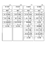
- the stepped speed change state of the transmission 1 typically includes the third engagement device C0 in the engaged state, and the power from the engine 4 is as follows, as shown in FIG.
- This is a state of transmission to the drive wheel 6 side via the first route R1 or the second route R2 to be described.
- the first engagement device C1 is in the engaged state
- the second engagement device C2 is in the released state
- the switching units 67 and 68 are in the neutral position.
- This is a power transmission path formed when any one of the three-speed gear stages 63 is in a fastening state (a state in which power is transmitted).
- the first path R1 includes at least one of the first engagement device C1, the first input shaft 13, and the odd-numbered shift stage group 11 (the first speed shift stage 61 and the third speed shift stage 63) from the engine 4.
- This is a path for transmitting power to the drive wheels 6 through the gear stage and the output shaft 15 in this order.
- the first engagement device C1 is in the released state
- the second engagement device C2 is in the engaged state
- the switching units 66 and 67 are in the neutral position.
- This is a power transmission path formed when any one of the fourth speed gears 64 is in the engaged state (a state in which power is transmitted).
- the second path R2 includes at least one of the second engagement device C2, the second input shaft 14, and the even-numbered speed stage group 12 (the second speed gear stage 62 and the fourth speed gear stage 64) from the engine 4.
- This is a path for transmitting power to the drive wheels 6 through the gear stage and the output shaft 15 in this order.
- the power from the engine 4 is transmitted to the first engagement device C1 or the second engagement device C2 via the third engagement device C0, the damper 7, and the like.
- the ECU 50 is based on, for example, the accelerator opening detected by the accelerator opening sensor (or the throttle opening detected by the throttle opening sensor), the vehicle speed detected by the vehicle speed sensor, and the like.
- a target output is calculated, and a target control amount that achieves the target output with minimum fuel consumption, for example, a target engine torque and a target engine speed, is calculated.
- the ECU 50 controls the output from the engine 4 by controlling the fuel injection timing of the fuel injection valve of the engine 4, the ignition timing of the spark plug, the throttle opening of the throttle device, and the like.
- the output of the engine 4 is controlled so that the engine torque becomes the engine torque and the engine speed becomes the target engine speed.
- the ECU 50 controls each part of the transmission 1 based on, for example, the accelerator opening detected by the accelerator opening sensor, the vehicle speed detected by the vehicle speed sensor, etc. You may make it control. In this case, the ECU 50 executes the shift control of the transmission 1 based on, for example, a shift map in which a plurality of shift lines and the like are defined according to the accelerator opening and the vehicle speed.
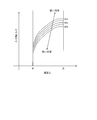
- the continuously variable transmission state of the transmission 1 refers to the rotational power from the engine 4 between the gear ratios of the gear stages constituting the odd gear group 11 and the even gear group 12.
- the gear ratio can be changed and output from the output shaft 15, and the gear ratio can be changed steplessly. That is, in the continuously variable transmission state, the transmission 1 can realize a gear ratio corresponding to at least the intermediate stages of the odd-numbered speed group 11 and the even-numbered speed group 12.
- the continuously variable transmission state of the transmission 1 is a state in which the rotational power from the engine 4 is shifted via the first input shaft 13, the second input shaft 14, and the differential mechanism 20. By controlling the rotation of the rotating machine 30 and adjusting the differential rotation of the differential mechanism 20, the continuously variable transmission state of the transmission 1 is realized.
- the third engagement device C0 is in the engaged state, as shown in FIG.
- This is a state of transmission to the drive wheel 6 side via the third route R3 or the fourth route R4 to be described.
- the third path R3 the first engagement device C1 is in the engaged state
- the second engagement device C2 is in the released state
- the switching units 66 and 67 are in the neutral position.
- This is a power transmission path formed when any one of the fourth speed gears 64 is in the engaged state (a state in which power is transmitted). That is, the third path R3 includes at least the engine 4 from the first engagement device C1, the first input shaft 13, the differential mechanism 20, the transmission unit 70, the second input shaft 14, and the even-numbered speed stage group 12 (second speed shift).
- the fourth path R4 the first engagement device C1 is in the released state, the second engagement device C2 is in the engaged state, and the switching units 67 and 68 are in the neutral position.
- the ECU 50 controls the rotation of the rotating machine 30 in a state in which the transmission 1 transmits the power from the engine 4 to the drive wheel 6 side via the third path R3 or the fourth path R4, and the differential mechanism 20.
- the gear ratio of the transmission 1 can be changed steplessly by adjusting the differential rotation.
- the ECU 50 changes the gear ratio in the continuously variable transmission state by controlling the amount of power generated by the rotating machine 30 when the transmission 1 is in the continuously variable transmission state.
- the power from the engine 4 is transmitted to the first engagement device C1 or the second engagement device C2 via the third engagement device C0, the damper 7, and the like. Further, the change of the gear ratio in the continuously variable transmission state of the transmission 1 will be described in detail later.
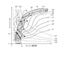
- the ECU50 can drive the engine 4 on an optimal fuel consumption line, for example, when the transmission 1 is a continuously variable transmission state, and can aim at the improvement of a fuel consumption performance by this.
- the optimum fuel consumption line is a set of operating points of the engine 4 that can operate the engine 4 with optimum fuel consumption (efficiently).
- the operating point of the engine 4 is an engine torque output from the engine 4 (hereinafter also referred to as “engine torque”) and an engine speed (hereinafter also referred to as “engine speed”). It depends on your needs.
- the optimum fuel efficiency line represents the relationship between the engine torque at which the engine 4 can be operated with the highest fuel efficiency, that is, the engine efficiency (engine efficiency) and the engine speed.
- the fuel consumption refers to the amount of fuel consumed per unit work, and corresponds to the amount of fuel required for the vehicle 2 to travel a unit distance or the distance that the vehicle 2 can travel with the unit fuel amount. . That is, the optimum fuel consumption line is set based on the engine speed and the engine torque at which the engine 4 can be operated with priority given to the distance that the vehicle 2 equipped with the engine 4 can travel with the unit fuel amount. This is determined in advance.
- the ECU 50 typically controls the output of the engine 4 so that the operating point of the engine 4 is located on the optimum fuel consumption line of the engine 4.
- the ECU 50 calculates based on, for example, the accelerator opening detected by the accelerator opening sensor (or the throttle opening detected by the throttle opening sensor), the vehicle speed detected by the vehicle speed sensor, and the like.
- Basic control is to calculate the target engine speed and target engine torque from the target output and the optimum fuel consumption line.
- the ECU 50 obtains the intersection (operating point) between the equal output line corresponding to the target output and the optimum fuel consumption line, and calculates the target engine speed and the target engine torque in accordance with this.
- the ECU 50 controls the output of the engine 4 so that the engine torque of the engine 4 becomes the target engine torque and the engine speed becomes the target engine speed, and also rotates the output shaft 15 (in other words, the vehicle speed).
- the gear ratio is controlled by controlling each part of the transmission 1 (the power generation amount of the rotating machine 30 here).
- the ECU 50 can switch between a stepped transmission state and a continuously variable transmission state of the transmission 1 as described below, for example.
- the ECU 50 places the first engagement device C1 in the engaged state and the second engagement device C2 in the released state, and changes the rotational power from the engine 4 by any one of the odd-numbered gear stages 11.
- the stepless speed change state that is, the state where the power is transmitted through the first route R1 (see FIG. 2) to the continuously variable speed change state.
- the ECU 50 first controls the rotating machine 30 so that the rotational speed of the second input shaft 14 (second input shaft rotational speed) corresponds to the current rotational speed of the output shaft 15 (output shaft rotational speed). Synchronize with the rotation speed.
- the ECU 50 synchronizes the rotational speed of the driven gear 62b of the second speed shift stage 62 of the second input shaft 14 or the driven gear 64b of the fourth speed shift stage 64 with the rotational speed of the output shaft 15. Are controlled so as to be substantially equal to each other.
- the ECU 50 shifts the rotational power from the engine 4 via the differential mechanism 20 by any one speed of the even-numbered speed group 12.
- the ECU 50 maintains the first engagement device C1 in the engaged state and the second engagement device C2 in the released state, and then the second speed gear stage 62 and the fourth speed gear stage by the switching unit 68.
- One of 64 (the gear stage whose rotation is synchronized by the above-described synchronization control) is set to the engaged state, and the switching unit 66 is set to the neutral position. That is, the ECU 50 puts the transmission 1 in a state of transmitting power through the third path R3 (see FIG. 2). And ECU50 implement
- the ECU 50 shifts from the continuously variable transmission state as described above to the stepped gear shifting state in which the rotational power from the engine 4 is shifted by any one gear position of the even-numbered gear group 12, the second engagement is performed.
- the combined device C2 is set to the engaged state
- the first engaging device C1 is set to the released state
- the transmission 1 is set to the state where power is transmitted by the second path R2 (see FIG. 2), and the control of the rotating machine 30 is finished.
- the ECU 50 sets the first engagement device C1 in the released state and the second engagement device C2 in the engaged state, and changes the rotational power from the engine 4 at any one of the even-numbered shift speed groups 12.
- the following control is performed when the stepped speed change state, i.e., the state in which power is transmitted through the second path R2 (see FIG. 2) shifts to the stepless speed change state.
- the ECU 50 first controls the rotating machine 30 so that the rotational speed of the first input shaft 13 (first input shaft rotational speed) corresponds to the current rotational speed of the output shaft 15 (output shaft rotational speed). Synchronize with the rotation speed.
- the ECU 50 rotates the drive gear 61a of the first speed gear 61 or the drive gear 63a of the third speed gear 63 according to the rotation speed of the first input shaft 13 and the rotation speed of the output shaft 15.
- the number of rotations of the rotating shaft 31 of the rotating machine 30 is controlled so that the numbers are synchronized with each other.
- the ECU 50 shifts the rotational power from the engine 4 via the differential mechanism 20 by any one gear of the odd gear group 11.
- the ECU 50 maintains the first engagement device C1 in the released state and the second engagement device C2 in the engaged state, and then the first speed gear stage 61 and the third speed gear stage are switched by the switching unit 66.
- One of 63 (the gear stage whose rotation is synchronized by the above-described synchronization control) is set to the engaged state, and the switching unit 68 is set to the neutral position. That is, the ECU 50 sets the transmission 1 in a state of transmitting power through the fourth path (see FIG. 2).
- the ECU 50 shifts from the continuously variable transmission state as described above to the stepped gear shifting state in which the rotational power from the engine 4 is shifted by any one gear of the odd gear group 11, the first engagement is performed.
- the combined device C1 is set to the engaged state
- the second engagement device C2 is set to the released state
- the transmission 1 is set to the state where power is transmitted by the first path R1 (see FIG. 2), and the control of the rotating machine 30 is finished.
- the switching of the transmission 1 described above from the stepped transmission state to the continuously variable transmission state and the change of the gear ratio in the continuously variable transmission state will be described with specific examples.
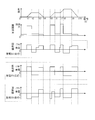
- an example will be described in which the rotating machine 30 is used to change from the first speed shift stage 61 to the second speed shift stage 62 through an intermediate stage in the continuously variable transmission state.
- the power from the engine 4 is transmitted from the first engagement device C1, the first input shaft 13, and the first speed shift stage 61. Is transmitted to the output shaft 15.
- the ECU 50 controls the rotation of the rotating machine 30, and the rotational speed N2i of the driven gear 62b and the rotational speed Nout of the output shaft 15 are controlled.
- the ECU 50 controls the rotation of the rotating machine 30 and sets the rotation speed Nc2 of the carrier 20C to 250 rpm, thereby setting the rotation speed Ns2 of the second sun gear 20S2 to 500 rpm.
- the ECU 50 reduces the rotational speed N2i of the driven gear 62b to 250 rpm and synchronizes with the rotational speed Nout of the output shaft 15.
- the ECU 50 maintains the first engagement device C1 in the engaged state and the second engagement device C2 in the released state.
- the unit 66 is set to the neutral position and the state is shifted to the continuously variable transmission state.
- the ECU 50 adjusts the power generation amount of the rotating machine 30 and adjusts the load torque that acts on the rotating shaft 31 according to the power generation load, so that the carrier force is generated by the reaction force.
- the rotational speed Nc of 20C is adjusted.
- the ECU 50 can change the speed ratio in the transmission 1 steplessly by adjusting the rotation speed Ns2 of the second sun gear 20S2 and adjusting the rotation speed Nout of the output shaft 15.
- the vehicle speed increases as the rotational speed Ns2 of the second sun gear 20S2 increases.
- the amount of power generated by the rotating machine 30 in the continuously variable transmission state is obtained by multiplying the torque of the carrier 20C by the differential rotational speed ⁇ Nc between the rotational speed Nc of the carrier 20C before synchronous control and the rotational speed Nc of the carrier 20C after synchronous control.
- the amount of power generation depends on the value.
- the ECU 50 increases the power generation amount of the rotating machine 30 and reduces the rotational speed Nc of the carrier 20C to 0, so that the speed change state is equivalent to the case where the second speed shift stage 62 is selected in the stepped speed change state. Become. In this state, the ECU 50 switches the second engagement device C2 to the engaged state and the first engagement device C1 to the released state. The state is selected. Along with this, the torque transmitted to the rotating shaft 31 decreases, so the ECU 50 ends the power generation in the rotating machine 30 and completes the transition to the second speed shift stage 62.
- the ECU 50 typically performs control as described above in the case of an upshift, and basically in the case of a downshift, basically uses various methods in the same manner as a general stepped transmission. What is necessary is just to downshift in the step shifting state.
- the ECU 50 can control the transmission 1 in the step-variable shifting state and the continuously variable shifting state. Further, the ECU 50 according to the present embodiment controls the engine 4, the first engagement device C1, the second engagement device C2, the third engagement device C0, and the rotating machine 30 in a coordinated manner. By using 30 as a prime mover together or selectively, the vehicle 2 can travel in various travel modes such as an engine travel mode, an HV travel mode, an EV travel mode, and a regenerative travel mode. Thereby, ECU50 can aim at the improvement of fuel consumption performance.
- the engine travel mode is, for example, a travel mode in which the vehicle 2 is traveled by the power of the engine 4 without depending on the power of the rotating machine 30.
- the ECU 50 can realize the engine travel mode by controlling the output of the engine 4 after the third engagement device C0 is in the engaged state. In this case, the ECU 50 sets the output of the rotating machine 30 to zero. Further, the ECU 50 places the transmission 1 in a stepped transmission state or a continuously variable transmission state, whereby the transmission 1 changes the power output from the engine 4 at a predetermined transmission ratio and transmits it to the drive wheels 6. To do.
- the HV travel mode is a travel mode in which the vehicle 2 travels with power from the engine 4 and power from the rotating machine 30.
- the ECU 50 realizes the HV travel mode by controlling the output of the rotating machine 30 after controlling the output of the engine 4 with the third engagement device C0 in the engaged state, similarly to the engine travel mode. be able to.
- the EV travel mode is a travel mode in which the vehicle 2 travels with the power of the rotating machine 30 instead of the power of the engine 4. That is, the EV travel mode is an MG drive mode by the rotating machine 30.
- the ECU 50 can realize the EV traveling mode by controlling the output of the rotating machine 30 with the third engagement device C0 in the released state. In this case, the ECU 50 sets the output of the engine 4 to 0 and keeps it in an inoperative state. That is, the ECU 50 according to the present embodiment controls the third engagement device C0 and the rotating machine 30 to release the third engaging device C0 and cause the vehicle 2 to travel by the rotational power output from the rotating machine 30.
- the control can be executed, and thereby the EV travel mode can be realized.
- the ECU 50 can disconnect the engine 4 from the power transmission device 5 that constitutes the drive system of the vehicle 2 by releasing the third engagement device C0. Thereby, the transmission 1 can reduce the friction loss by the engine 4.
- the ECU 50 when the ECU 50 causes the third engagement device C0 to be in the released state and causes the vehicle 2 to travel by the rotational power output from the rotating machine 30 as in the EV travel mode, the ECU 50 performs the first engagement device C1 and the second engagement device.
- the device C2 is controlled to bring the first engagement device C1 and the second engagement device C2 into an engaged state.
- the first input shaft 13 and the second input shaft 14 do not rotate differentially but rotate integrally, and the rotational power from the rotating machine 30 is supplied to the odd-numbered shift stage group 11 or even number.
- the speed can be changed by any one speed of the speed group 12 and output from the output shaft 15 to be transmitted to the drive wheels 6.
- the ECU 50 uses the power generated by the engine 4 by bringing the third engagement device C0 into the engaged state with the first engagement device C1 and the second engagement device C2 in the engaged state. Electric power can also be generated by the rotating machine 30.
- the regenerative travel mode is a travel mode in which regenerative braking is performed by the rotating machine 30 when the vehicle 2 is decelerated.
- the ECU 50 can realize the regenerative travel mode by performing power generation control of the rotating machine 30 when the vehicle 2 is decelerated. That is, the ECU 50 controls the rotating machine 30 when the vehicle 2 is decelerated, and from the drive wheel 6 side of the vehicle 2, the differential gear 8, the driven gear 17, the drive gear 16, the output shaft 15, the odd speed stage group 11, or
- the rotating machine 30 generates electric power using the rotational power transmitted to the rotating machine 30 via any one of the even-numbered shifting stage groups 12, the differential mechanism 20, the gear 32, the gear 33, the rotating shaft 31, and the like.
- Control for storing power in the power storage device 40 can be executed, and thereby the regenerative travel mode can be realized.
- the ECU 50 may place the third engagement device C0 in either the engaged state or the released state, for example, when the required braking force can be satisfied only by the regenerative braking force by the rotating machine 30. Brings the third engagement device C0 into a released state.
- the ECU 50 engages the third engagement device C0 and uses the engine brake (engine brake) by the engine 4 as well. Also good.
- And ECU50 of this embodiment typically controls the engine 4 and the rotary machine 30, and switches various driving modes based on the electrical storage state of the electrical storage apparatus 40, or the driving state of the vehicle 2.
- FIG. 1 A block diagram illustrating an exemplary computing environment in accordance with the present disclosure.
- the ECU 50 makes the output of the engine 4 relatively low when the power storage amount (SOC) of the power storage device 40 is relatively large compared to when the power storage amount of the power storage device 40 is relatively small.
- SOC power storage amount
- ECU 50 relatively lowers the output of engine 4 when the amount of power stored in power storage device 40 is equal to or greater than a preset allowable upper limit, and vehicle 2 is driven by the rotational power output from rotating machine 30.
- the allowable upper limit value is an upper limit threshold set with respect to the amount of power stored in the power storage device 40, and may be set in advance based on actual vehicle evaluation or the like.
- the ECU 50 may cause the vehicle 2 to travel in the HV traveling mode by assisting with the rotational power output from the rotating machine 30 after the output of the engine 4 is relatively low.
- the vehicle 2 may be caused to travel in the EV traveling mode by setting the output to 0 to be in an inoperative state and performing output control of the rotating machine 30.
- the ECU 50 can optimally perform the power running of the rotating machine 30 based on the amount of power stored in the power storage device 40 and the like.
- the ECU 50 uses the surplus power stored in the power storage device 40 to By powering, surplus power can be processed efficiently.
- the transmission 1 can aim at the improvement of a fuel consumption performance.
- the ECU 50 may determine that the vehicle 2 is in the steady running state when the amount of change in the parameter representing the running state of the vehicle 2 is less than a preset steady state determination specified value.
- a parameter representing the traveling state of the vehicle 2 a throttle opening detected by a throttle opening sensor constituting the vehicle state detection device 51, an accelerator opening detected by an accelerator opening sensor, and the like can be used.
- the ECU 50 can determine that the throttle opening is small and that the vehicle is in a substantially steady running state.
- the regular determination prescribed value is a threshold value set for the amount of change in parameters (throttle opening, accelerator opening, etc.) representing the traveling state of the vehicle 2 in order to determine the steady traveling state of the vehicle 2. It may be set in advance based on actual vehicle evaluation or the like.
- the ECU 50 may change the steady state determination specified value used for determining the steady running state of the vehicle 2 as described above based on the amount of power stored in the power storage device 40.
- the ECU 50 relatively increases the steady-state determination specified value when the storage amount of the power storage device 40 is relatively large, and relatively sets the steady-state determination specified value when the storage amount of the storage device 40 is relatively small. Make it smaller.
- the ECU 50 can relatively widen the region where the vehicle 2 is determined to be in the steady travel state by relatively increasing the steady state determination specified value when the power storage amount of the power storage device 40 is relatively large.
- the region in which the vehicle 2 is driven by the rotational power output from the rotating machine 30 can be relatively narrowed by the EV driving mode, the HV driving mode, and the like.
- the ECU 50 can suppress a mode in which the vehicle 2 is caused to travel by the rotational power output from the rotating machine 30 when the power storage amount of the power storage device 40 is relatively small.
- the electric power stored in 40 can be saved.
- the ECU 50 controls the engine 4 and the rotating machine 30 based on the power storage state of the power storage device 40, and relatively reduces the power generation amount by the rotating machine 30 when the power storage amount of the power storage device 40 is relatively large.
- the amount of electricity stored in the power storage device 40 is relatively small, it is possible to execute control for relatively increasing the amount of power generated by the rotating machine 30.
- the ECU 50 of the present embodiment changes the stepped speed change state and the continuously variable speed change state of the transmission 1 based on, for example, an operation characteristic map (or a mathematical model corresponding thereto) as shown in FIG.
- FIG. 3 is a diagram showing an example of operating characteristics of the engine 4 of the power train 3, where the horizontal axis is the engine speed and the vertical axis is the engine torque.
- the solid line L21 represents the above-mentioned optimum fuel consumption line.
- solid lines L22 to L30 represent an equal fuel consumption efficiency line (for example, an equal fuel consumption rate curve).
- the equal fuel efficiency lines L22 to L30 are sets of operating points of the engine 4 at which the fuel efficiency (for example, fuel consumption rate) of the engine 4 is equal.
- the region surrounded by the equal fuel efficiency line L22 is the region with the highest fuel efficiency.
- the fuel efficiency is set every 5%.
- Dotted lines L31 to L34 represent equal output (power) lines.
- the equal output lines L31 to L34 are a set of operating points of the engine 4 at which the outputs of the engine 4 are equal.
- a dotted line L35 represents an example of the transition of the operating point of the engine 4 when the transmission 1 is shifted only in the stepped shift state.
- the equal fuel consumption efficiency lines L22 to L30 and the equal output lines L31 to L34 are shown as an example, and may include a plurality of equal fuel consumption efficiency lines and equal output lines.
- the intervals between the equal fuel efficiency lines and the equal output lines may be appropriately interpolated.
- the operation characteristic map illustrated in FIG. 3 is created in advance according to actual vehicle evaluation and stored in the storage unit.
- the ECU 50 controls the power generation by the rotating machine 30 by controlling the engine 4 and the rotating machine 30 based on, for example, the optimum fuel consumption areas TA, TB, and TC shown in FIG.
- the ECU 50 controls the engine 4 and the rotating machine 30 to generate electric power with the rotating machine 30 using the power generated by the engine 4.
- the output of the engine 4 can be controlled so as to be positioned within the optimum fuel consumption areas TA, TB, and TC of the engine 4 set according to the amount of stored power of 40.
- the optimum fuel consumption areas TA, TB, and TC are areas set in advance according to the amount of power stored in the power storage device 40.
- the areas are three areas, but may be further divided into more areas. .
- Each optimum fuel consumption area TA, TB, TC includes an optimum fuel consumption line L21, and is a region on the high engine speed, low engine torque side with respect to the optimum fuel consumption line L21. It is set as an area within a predetermined range.
- the optimum fuel efficiency area TA is an area that is applied when the power storage amount of the power storage device 40 is insufficient and the required power generation amount is relatively large.
- the optimal fuel efficiency region TC is a region that is applied when the amount of power stored in the power storage device 40 is excessive and the required amount of power generation is relatively small.
- the optimum fuel consumption region TB is a region that is applied when the amount of electricity stored in the power storage device 40 is appropriate and the required power generation amount is about halfway between the optimum fuel consumption region TA and the optimum fuel consumption region TC.
- Each optimum fuel consumption area TA, TB, TC is the area where the optimum fuel consumption area TA is the narrowest, and is wide in the order of the optimum fuel consumption area TB and the optimum fuel consumption area TC on the high engine speed and low engine torque side.
- Each optimum fuel consumption area TA, TB, TC is set in advance in the operation characteristic map of FIG. 3 (or a mathematical model corresponding thereto) after the relationship with the amount of power stored in the power storage device 40 is set in advance according to the actual vehicle evaluation or the like. It is stored in the storage unit in the form.
- the ECU 50 detects the current engine speed and engine torque by various known methods based on the detection results of the engine speed sensor, the throttle opening sensor, etc., for example, and calculates the current engine speed and engine torque. Based on this, the operating point A is specified. If the vehicle speed of the vehicle 2 rises in this stepped speed change state, the operating point A first leaves the optimum fuel consumption area TA, then leaves the optimum fuel consumption area TB, and finally leaves the optimum fuel consumption area TC. It will be.
- the ECU 50 monitors the amount of charge (SOC) of the power storage device 40 based on the detection result of the state of charge detector, and selects one of the optimum fuel consumption areas TA, TB, TC according to the magnitude of the amount of charge. Select.
- the ECU 50 selects the optimum fuel consumption area TA when it is determined that the power storage amount of the power storage device 40 is insufficient based on a preset power storage amount determination value or the like, and when it is determined that it is appropriate.
- the optimum fuel consumption region TB is selected and it is determined that the fuel consumption is excessive, the optimum fuel consumption region TC is selected.
- the ECU 50 shifts the state of the transmission 1 to the continuously variable transmission state when the operating point A leaves the optimal fuel consumption area TA in a state where the amount of power stored in the power storage device 40 is excessive and the optimal fuel consumption area TC is selected.
- the ECU 50 performs an equal output line passing through the operating point A (an equal output line between the equal output line L33 and the equal output line L34, or an interpolation value thereof) and an optimum fuel consumption line.
- An operating point B engine speed, engine torque
- the output of the engine 4 is controlled based on the operating point B, and the transmission ratio of the transmission 1, in other words, the rotating machine 30 power generation amounts are controlled.
- the ECU 50 can relatively prevent the transmission 1 from shifting to the continuously variable transmission state when the power storage amount of the power storage device 40 is excessive, so that the power generation amount by the rotating machine 30 is suppressed. It is possible to prevent the surplus power of the power storage device 40 from increasing.
- the ECU 50 continuously changes the state of the transmission 1 when the operating point A leaves the optimum fuel consumption area TA in a state where the storage amount of the power storage device 40 is insufficient and the optimum fuel consumption area TA is selected. Transition to the state.
- the ECU 50 causes the transmission 1 to shift to the continuously variable transmission state relatively early, generates power with the rotating machine 30, and stores power in the power storage device 40. can do.
- the ECU 50 changes the state of the transmission 1 to the continuously variable transmission state when the operating point A leaves the optimum fuel consumption region TB in a state where the amount of electricity stored in the power storage device 40 is appropriate and the optimum fuel consumption region TB is selected. Transition.
- the ECU 50 controls the engine 4 and the rotating machine 30 based on the power storage state of the power storage device 40.
- the power generation amount by the rotary machine 30 The power generation amount by the rotating machine 30 can be relatively increased when the power storage amount of the power storage device 40 is relatively small.
- the ECU 50 can appropriately maintain the amount of power stored in the power storage device 40.
- the output energy of the engine 4 is the energy for driving the vehicle 2 and the rotation speed. It is consumed as energy generated by the machine 30.
- the ECU 50 in the continuously variable transmission state, the ECU 50 expects the power generation amount of the rotating machine 30 as described above, and the operating point of the engine 4 is selected according to the power storage amount of the power storage device 40.
- the output of the engine 4 is controlled so as to be positioned on the optimal fuel consumption line L21 so as to be positioned within the optimal fuel consumption areas TA, TB, TC of the engine 4.
- the ECU 50 controls the engine 4 so that the engine 4 outputs extra power commensurate with the amount absorbed by the rotating machine 30 in the continuously variable transmission state of the transmission 1.
- the ECU 50 can appropriately generate power by the rotating machine 30 while realizing an appropriate acceleration performance commensurate with the acceleration performance required by the driver in the vehicle 2 and ensuring a more suitable power performance.
- the ECU 50 can achieve both improvement in fuel efficiency and securing suitable power performance.
- the ECU 50 stores the amount of electricity stored in the electricity storage device 40 when the amount of electricity stored in the electricity storage device 40 is less than or equal to a preset allowable lower limit in a state where the vehicle 2 is driven by the rotational power output from the rotating machine 30.
- a preset allowable lower limit value As compared with the case where the value is larger than the allowable lower limit value, it is possible to execute control in which the output of the engine 4 is made relatively large, and the power generated by the engine 4 is generated by the rotating machine 30 and stored in the power storage device 40.
- the allowable lower limit value is a lower limit threshold set with respect to the amount of power stored in the power storage device 40 and may be set in advance based on actual vehicle evaluation or the like. For example, the power storage device 40 is not overdischarged.
- the ECU 50 immediately sets the transmission 1 to the continuously variable transmission state, relatively increases the output of the engine 4, generates power with the rotating machine 30 using the power generated by the engine 4, and stores the power in the power storage device 40. .
- the ECU 50 may restart the engine 4 and relatively increase the output of the engine 4 when the engine 4 is in an inoperative state.
- the ECU 50 can suppress, for example, overdischarge of the power storage device 40, and can improve the life of the power storage device 40, for example.
- control routines are repeatedly executed at a control cycle of several ms to several tens of ms (the same applies hereinafter).
- the ECU 50 detects and monitors the power storage state of the power storage device 40 based on the detection result by the charge state detector of the vehicle state detection device 51 (step ST1).
- step ST2 determines whether the electrical storage amount (SOC) of the electrical storage apparatus 40 is more than the preset allowable upper limit (step ST2).
- step ST2 determines that the amount of power stored in the power storage device 40 is equal to or greater than the allowable upper limit (step ST2: Yes)
- the ECU 50 controls the transmission 1 and the engine 4 and immediately sets the travel mode of the vehicle 2 to EV travel.
- the mode is set (step ST11), and the process proceeds to step ST15.
- the ECU 50 sets an optimum fuel consumption region corresponding to the amount of power stored in the power storage device 40 based on, for example, the optimum fuel consumption region map illustrated in FIG. 5 (or a mathematical model corresponding thereto).
- the horizontal axis indicates the amount of stored electricity (SOC), and the vertical axis indicates the optimal fuel consumption area.
- the optimum fuel consumption area map describes the relationship between the amount of electricity stored in the power storage device 40 and the selected optimum fuel consumption area.
- the optimum fuel consumption area map is stored in the storage unit of the ECU 50 after the relationship between the power storage amount of the power storage device 40 and the optimum fuel consumption areas TA, TB, and TC is set in advance based on actual vehicle evaluation or the like.
- the optimum fuel consumption region is set to be the optimum fuel consumption region TA, the optimum fuel consumption region TB, and the optimum fuel consumption region TC in order from the smaller (smaller) charged amount.
- the charged amount on the upper limit side of the optimum fuel consumption area TC corresponds to the above-described allowable upper limit value
- the charged amount on the lower limit side of the optimum fuel consumption area TA corresponds to the above-described allowable lower limit value.
- the ECU 50 determines an optimal fuel consumption region corresponding to the current power storage amount of the power storage device 40 from the optimal fuel consumption region map based on the current power storage amount of the power storage device 40.
- step ST3 the ECU 50 determines that the optimal fuel consumption region corresponding to the current power storage amount of the power storage device 40 is the optimal fuel consumption region TC based on the current power storage amount of the power storage device 40 and the optimal fuel consumption region map illustrated in FIG. It is determined whether or not.
- step ST3 When the ECU 50 determines that the optimum fuel consumption region corresponding to the current power storage amount of the power storage device 40 is the optimum fuel consumption region TC (step ST3: Yes), the ECU 50 selects the optimum fuel consumption region TC as the optimum fuel consumption region (step ST4). The process proceeds to step ST9.
- step ST3 When the ECU 50 determines that the optimum fuel consumption region corresponding to the current power storage amount of the power storage device 40 is not the optimal fuel consumption region TC (step ST3: No), the optimal fuel consumption region corresponding to the current power storage amount of the power storage device 40 is optimal. It is determined whether or not the fuel consumption region TB is present (step ST5).
- step ST5 When the ECU 50 determines that the optimum fuel consumption region corresponding to the current power storage amount of the power storage device 40 is the optimum fuel consumption region TB (step ST5: Yes), the ECU 50 selects the optimum fuel consumption region TB as the optimum fuel consumption region (step ST6). The process proceeds to step ST9.
- step ST5 determines that the optimal fuel consumption region corresponding to the current power storage amount of the power storage device 40 is not the optimal fuel consumption region TB (step ST5: No), the optimal fuel consumption region corresponding to the current power storage amount of the power storage device 40 is optimal. It is determined whether or not the fuel consumption area TA is present (step ST7).
- step ST7 When ECU 50 determines that the optimum fuel consumption area corresponding to the current power storage amount of power storage device 40 is optimum fuel consumption area TA (step ST7: Yes), ECU 50 selects optimum fuel consumption area TA as the optimum fuel consumption area (step ST8). The process proceeds to step ST9.
- the ECU50 grasps
- the ECU 50 uses the vehicle state detection device 51 to, for example, information related to the engine 4 such as the engine speed and throttle opening, current gear speed / transmission ratio, information about the speed of each part such as the speed of each part, and a shift map.
- the ECU 50 determines whether or not the amount of change in the throttle opening is equal to or greater than a regular determination specified value (step ST10). Thereby, the ECU 50 determines whether or not the vehicle 2 is not in a steady running state, in other words, whether or not the engine 4 is in a low load state in which the engine efficiency of the engine 4 tends to be relatively low.
- the ECU 50 will be described as determining whether or not the vehicle 2 is not in a steady running state by determining whether or not the amount of change in the throttle opening is equal to or greater than a steady determination specified value. Alternatively, it may be determined whether or not the engine 4 is not in a low load state by determining whether or not the throttle opening itself is equal to or greater than the steady determination value for the throttle opening.
- step ST10 determines that the amount of change in the throttle opening is less than the regular determination prescribed value (step ST10: No), that is, when it is determined that the vehicle 2 is in the steady running state (low load state), the transmission 1 and the engine 4 are controlled to set the travel mode of the vehicle 2 to the EV travel mode (step ST11), and the process proceeds to step ST15.
- the ECU 50 determines the optimum fuel consumption region (for example, the optimum fuel consumption region in FIG. 3) in which the current operating speed determined from the current engine speed and the engine torque is selected in the process of step ST4, step ST6, or step ST8. (TA, TB, TC) is determined (step ST13).
- step ST13 When the ECU 50 determines that the current operating point is located within the optimum fuel efficiency range (step ST13: Yes), the ECU 50 controls the transmission 1 to place the transmission 1 in a stepped transmission state (step ST14), and step ST15. Move on to processing. In this case, the ECU 50 selects either one of the odd-numbered speed group 11 or the even-numbered speed group 12 according to the traveling state of the vehicle 2.
- step ST15 the ECU 50 determines whether or not the brake (braking device) of the vehicle 2 is operating according to the brake operation or the like by the driver (step ST15). It is determined whether or not there is.
- step ST15 If the ECU 50 determines that the brake of the vehicle 2 is operating (step ST15: Yes), that is, determines that the vehicle 2 is in a decelerating running state, the ECU 50 controls the transmission 1 to drive the vehicle 2 The mode is set to the regenerative travel mode (step ST16), and the process returns to the process of step ST15 to repeatedly execute the transition process.
- step ST15: No the ECU 50 ends the current control cycle and shifts to the next control cycle.
- step ST13 If the ECU 50 determines in step ST13 that the current operating point is located outside the optimum fuel efficiency range (step ST13: No), the current operating point is a region on the low engine speed and high engine torque side from the optimal fuel efficiency line L21. It is determined whether or not the position is within (for example, the region above the optimum fuel consumption line L21 in FIG. 3) (step ST17).
- step ST17 When the ECU 50 determines that the current operating point is not located within the region of the low engine speed and high engine torque side from the optimum fuel consumption line L21 (step ST17: No), the ECU 50 controls the transmission 1 to control the transmission. 1 is set to a continuously variable transmission state (step ST18), and the process proceeds to step ST15. In this case, the ECU 50 controls the speed ratio in the continuously variable transmission state by adjusting the amount of power generated by the rotating machine 30 according to the traveling state of the vehicle 2.
- step ST17 If the ECU 50 determines that the current operating point is located within the region of the lower engine speed and higher engine torque side than the optimal fuel consumption line L21 (step ST17: Yes), the ECU 50 controls the transmission 1 and the engine 4.
- the travel mode of the vehicle 2 is set to the HV travel mode (step ST19), and the process proceeds to step ST15.
- the ECU 50 assists the engine 4 with the rotational power output from the rotating machine 30.
- the ECU 50 may assist the engine 4 by powering the rotating machine 30 after setting the transmission 1 in the engaged state equivalent to the continuously variable transmission state.
- the ECU 50 performs output control so that the operating point of the engine 4 is positioned on the optimum fuel consumption line L21, and supplements the insufficient power by causing the rotating machine 30 to power and assist.
- the ECU 50 determines that the amount of power stored in the power storage device 40 is equal to or less than the allowable lower limit value, the ECU 50 immediately shifts the transmission 1 to the continuously variable transmission state, and converts the power generated by the rotating machine 30 into the power storage device 40. Can be stored.
- the transmission 1 and the ECU 50 configured as described above connect the rotating machine 30 to the first input shaft 13 and the second input shaft 14 of the DCT type transmission mechanism 10 via the differential mechanism 20, and The combined device C1 and the second engaging device C2 are controlled, and the differential rotation of both shafts is controlled by the rotating machine 30.
- the transmission 1 and the ECU 50 can switch the state of the transmission 1 between a dual clutch stepped transmission state and a continuously variable transmission state.
- the transmission 1 and the ECU 50 can achieve a travel close to the optimal fuel consumption line such as CVT in the DCT, so that the fuel consumption performance can be improved.
- the ECU 50 of the present embodiment controls the third engagement device C0 and the rotating machine 30 in, for example, an operation region where the engine efficiency of the engine 4 is relatively poor, so that the third engagement device C0 is Control in which the vehicle 2 is driven by the rotational power output from the rotating machine 30 in the released state can be executed.
- the ECU50 can drive the vehicle 2 using the rotational power which the rotary machine 30 outputs.
- the transmission 1 and the ECU 50 efficiently operate the surplus power stored in the power storage device 40 after suppressing the operation of the engine 4 in the operation region where the engine efficiency is poor according to the traveling state of the vehicle 2.
- the vehicle 2 can be run by using it.
- the transmission 1 and the ECU 50 can efficiently process surplus power and suppress energy waste, thereby improving fuel efficiency.
- the transmission 1 and the ECU 50 set the third engagement device C0 in the released state, thereby The engine 4 can be disconnected from the transmission device 5. Therefore, the transmission 1 and the ECU 50 can reduce the friction loss due to the engine 4, can improve the driving efficiency of the rotating machine 30, and can further improve the fuel efficiency.
- the ECU 50 switches the driving mode of the vehicle 2 based on the power storage state of the power storage device 40, the driving state of the vehicle 2, and the like, or appropriately switches the shift state of the transmission 1, thereby Power generation and charging can be performed optimally.
- the transmission 1 and the ECU 50 can appropriately maintain the amount of power stored in the power storage device 40, and can achieve both improvement in fuel efficiency and improvement in the life of the power storage device 40, for example.
- the transmission 1 and the ECU 50 can appropriately maintain the amount of power stored in the power storage device 40, for example, it is possible to suppress an increase in the size of the power storage device 40, thereby improving mountability and manufacturing cost.
- the vehicle mass can be reduced and the fuel efficiency can be improved in this respect as well.
- FIG. 6 shows an example of the operation of the transmission 1 configured as described above.
- the horizontal axis represents the time axis
- the vertical axis represents the vehicle speed, the engine efficiency, and the power generation / discharge amount of the rotating machine in order from the upper side.
- the power generation / discharge amount of the rotating machine represents the case where the optimum fuel consumption area TA is selected in order from the upper side, the optimum fuel consumption area TB is selected, and the optimum fuel consumption area TC is selected. ing.
- the transmission 1 and the ECU 50 of this embodiment when the vehicle 2 starts accelerating travel at time t1, the amount of power stored in the power storage device 40 is insufficient, and the optimum fuel consumption area TA is selected. If the power storage amount of the power storage device 40 is appropriate and the optimum fuel efficiency region TB is selected, the rotating device 30 generates power and charges the power storage device 40. On the other hand, the transmission 1 and the ECU 50, when the amount of power stored in the power storage device 40 is excessive and the optimum fuel efficiency region TC is selected, The surplus power is appropriately processed by discharging (powering) the rotating machine 30 and causing the vehicle 2 to travel in the EV travel mode using the surplus power.
- the transmission 1 and the ECU 50 operate in the same manner during acceleration travel from time t5 to time t6 and during acceleration travel from time t7 to time t8.
- the transmission 1 and the ECU 50 for example, when the amount of power stored in the power storage device 40 falls below the allowable lower limit value during acceleration travel from time t5 to time t6, the rotating machine 30 Is switched from the discharging (power running) state to the power generation state, and the power storage device 40 is charged (including the acceleration from time t7 to time t8).
- the transmission 1 and the ECU 50 discharge (rotate) the rotating machine 30 in any case because the engine efficiency of the engine 4 becomes relatively poor when the vehicle 2 shifts to steady running at time t2.
- the vehicle 2 is caused to travel in the EV traveling mode.
- the transmission 1 and the ECU 50 have an earlier time when the amount of power stored in the power storage device 40 falls below the allowable lower limit compared to the other cases.
- the rotating machine 30 is switched from the discharging (powering) state to the power generation state, and the power storage device 40 is charged.
- the transmission 1 and the ECU 50 operate in the same manner during steady running from time t6 to time t7 and during steady running from time t8 to time t9.
- the transmission 1 and the ECU 50 generate power by the rotating machine 30 and charge the power storage device 40 in all cases until time t4 when the vehicle 2 shifts to decelerating travel at time t3. 2 is run in the regenerative running mode.
- the transmission 1 and the ECU 50 operate in the same manner during deceleration traveling from time t9 to time t10.
- the transmission 1 and the ECU 50 of the present embodiment are configured such that the engine 4, the first engagement device C1, the second engagement device C2, and the third engagement are based on the storage state of the storage device 40, the traveling state of the vehicle 2, and the like.
- Optimal power running, power generation, and charging by the rotating machine 30 by controlling the combined device C0 and the rotating machine 30 and switching the driving mode of the vehicle 2 or switching the shifting state of the transmission 1 as appropriate. Can do.
- the transmission 1 and the ECU 50 can appropriately maintain the amount of power stored in the power storage device 40.
- the transmission 1 and the ECU 50 according to the embodiment described above can appropriately use the dual clutch stepped transmission state and the continuously variable transmission state, and the rotating machine 30 is stored in the power storage device 40. Since the vehicle 2 can be driven by the rotational power output using electric power, the fuel efficiency can be improved.
- FIG. 7 is a diagram illustrating an example of a shift speed efficiency map of the transmission according to the second embodiment.
- FIG. 8 is a diagram illustrating an example of a differential mechanism efficiency map of the transmission according to the second embodiment.
- FIG. 9 is a flowchart illustrating an example of control in the transmission according to the second embodiment.
- the vehicle transmission and the control device according to the second embodiment are different from the first embodiment in that they can be switched between a stepped transmission state and a continuously variable transmission state according to efficiency.
- action, and effect which are common in embodiment mentioned above, the overlapping description is abbreviate
- FIG. 1 etc. are referred suitably for each structure of the transmission for vehicles which concerns on Embodiment 2, and a control apparatus.
- the ECU 50 of this embodiment can be controlled so that the efficiency is relatively higher between the stepped transmission state and the continuously variable transmission state of the transmission 201 as the vehicle transmission.
- the ECU 50 has a relative efficiency between the stepped speed change state and the stepless speed change state in a state where the operating point of the engine speed and the engine torque is located within the optimum fuel efficiency range. Control is possible so that the higher state is achieved.
- the ECU 50 compares the efficiency in the stepped speed change state with the efficiency in the stepless speed change state, and controls the transmission 201 so as to be in a higher efficiency state based on the comparison result.
- the efficiency here is typically the total efficiency in the power train 3, and includes at least the engine efficiency (engine efficiency) of the engine 4 and the power transmission efficiency of the transmission 201 (transmission mechanism 10). Is included.
- the ECU 50 outputs the iso-output line passing through the current operating point specified in FIG. 3 as the efficiency at the gear ratio between the current gear and the next gear, that is, the efficiency in the non-electric gear shift state. And an operating point that is the intersection of the optimum fuel consumption line L21 and the efficiency at the predicted operating point in the continuously variable transmission state is calculated. That is, the ECU 50 calculates the efficiency at the predicted operating point in the continuously variable transmission state that is the same output as the current operating point on the optimal fuel consumption line L21.
- the efficiency other than the engine efficiency of the engine 4 and the power transmission efficiency in the transmission 201 can be regarded as substantially equal between the current operating point and the predicted operating point in the continuously variable transmission state. Therefore, the ECU 50 compares the current operating point efficiency ⁇ a with the predicted operating point efficiency ⁇ b in the continuously variable transmission state based on the engine efficiency of the engine 4 and the transmission efficiency of the transmission 201.
- the transmission efficiency of the transmission 201 in the stepped speed change state can be calculated based on the shift speed efficiency.
- the gear speed efficiency is the power transmission efficiency at each gear speed of the odd speed gear group 11 and the even speed gear group 12.
- the transmission efficiency of the transmission 201 in the continuously variable transmission state can be calculated based on the differential mechanism efficiency in addition to the above-described gear speed efficiency.
- the differential mechanism efficiency is power transmission efficiency in the differential mechanism 20.
- the ECU 50 uses, for example, the following formulas (1) and (2), and the efficiency ⁇ a of the current operating point in the step-variable shifting state and the efficiency of the predicted operating point in the continuously variable shifting state: ⁇ b can be calculated.
- ⁇ a engine efficiency ⁇ gear stage efficiency (1)
- ⁇ b engine efficiency ⁇ gear stage efficiency ⁇ differential mechanism efficiency (2)
- the ECU 50 determines the engine efficiency of the engine 4 from the current operating point and the predicted operating point in the continuously variable transmission state based on, for example, an operating characteristic map (or a mathematical model corresponding thereto) as shown in FIG. May be calculated.
- the motion characteristic map is created in advance according to the actual vehicle evaluation and stored in the storage unit.
- This shift speed efficiency map describes the relationship among the engine speed, the input shaft torque, and the shift speed efficiency.
- the gear stage efficiency map is stored in advance as a three-dimensional map in the storage unit of the ECU 50 after the relationship between the input shaft torque and the gear stage efficiency at each engine speed is set in advance based on actual vehicle evaluation and the like.
- the shift speed efficiency map decreases relatively as the engine speed increases, and increases relatively as the input shaft torque increases.
- the ECU 50 calculates the input shaft torque at each operating point based on the engine rotational speed, engine torque at each operating point, various detection results by the vehicle state detection device 51, and the like.
- the ECU 50 calculates the gear speed efficiency at each operating point from the engine speed and the input shaft torque based on the gear speed efficiency map.
- the shift speed efficiency map of FIG. 7 is merely an example, and the present invention is not limited to this.
- the speed ratio is [the number of rotations of the second input shaft 14 / the number of rotations of the first input shaft 13] when the transmission 201 is transmitting power through the third path R3 (see FIG. 2). Equivalent to.
- the speed ratio corresponds to [the number of rotations of the first input shaft 13 / the number of rotations of the second input shaft 14] when the transmission 201 transmits power through the fourth path R4 (see FIG. 2).
- the differential mechanism efficiency includes a power loss acting on the rotating machine 30.
- the differential mechanism efficiency map describes the relationship among the speed ratio, the input shaft torque, and the differential mechanism efficiency.
- the differential mechanism efficiency map is stored in advance as a three-dimensional map in the storage unit of the ECU 50 after the relationship between the input shaft torque and the differential mechanism efficiency at each speed ratio is set in advance based on actual vehicle evaluation and the like. .
- this differential mechanism efficiency map the differential mechanism efficiency becomes relatively higher as the speed ratio becomes smaller, and becomes relatively higher as the input shaft torque becomes larger.
- the ECU 50 is based on various detection results by the vehicle state detection device 51 such as the engine speed, the engine torque, the first input shaft speed, and the second input shaft speed at the predicted operating point in the continuously variable transmission state.
- the input shaft torque and speed ratio at the operating point are calculated.
- the ECU 50 calculates the differential mechanism efficiency at the operating point from the speed ratio of the operating point and the input shaft torque based on the differential mechanism efficiency map.
- the differential mechanism efficiency map of FIG. 8 is merely an example, and the present invention is not limited to this.
- the ECU 50 uses the equations (1), (2), etc., based on the engine efficiency, the shift speed efficiency, and the differential mechanism efficiency calculated as described above, and the efficiency of the current operating point in the stepped speed change state. ⁇ a and the efficiency ⁇ b of the predicted operating point in the continuously variable transmission state are calculated. Then, the ECU 50 compares the efficiency ⁇ a and the efficiency ⁇ b, and controls the transmission 201 so that the efficiency becomes higher.
- step ST13 If the ECU 50 determines in step ST13 that the current operating point is located within the optimum fuel efficiency range (step ST13: Yes), the efficiency of the transmission 201 in the stepped shift state is greater than the efficiency in the continuously variable shift state. Is determined (step ST200). As described above, the ECU 50 calculates the efficiency of the transmission 201 in the stepped transmission state and the efficiency in the continuously variable transmission state, and compares them.
- step ST200 determines that the efficiency of the transmission 201 in the stepped transmission state is equal to or higher than the efficiency in the continuously variable transmission state (step ST200: Yes)
- the ECU 50 controls the transmission 201 to include the transmission 201.
- the step shift state is set (step ST14), and the process proceeds to step ST15.
- step ST200 determines that the efficiency of the transmission 201 in the stepped transmission state is less than the efficiency in the continuously variable transmission state (step ST200: No)
- the ECU 50 controls the transmission 201 to make the transmission 201 non-effective.
- the step shift state is set (step ST18), and the process proceeds to step ST15.
- the transmission 201 and the ECU 50 according to the embodiment described above can appropriately use the dual clutch stepped transmission state and the continuously variable transmission state, and the rotating machine 30 is stored in the power storage device 40. Since the vehicle 2 can be driven by the rotational power output using electric power, the fuel efficiency can be improved.
- the transmission 201 and the ECU 50 compare the efficiency in the stepped speed change state with the efficiency in the continuously variable speed change state so that the efficiency is relatively higher. Since it controls, the improvement effect of a fuel consumption performance can further be heightened.
- FIG. 10 is a schematic configuration diagram of a vehicle on which the transmission according to the third embodiment is mounted.
- the vehicle transmission and the control device according to the third embodiment are different from the first and second embodiments in that a first brake and a second brake are provided.
- a transmission 301 as a vehicle transmission includes a dual clutch type transmission mechanism 10 including a first engagement device C1 and a second engagement device C2.
- a first brake B1 and a second brake B2 are further provided.
- the first brake B1 can brake the rotation of the first input shaft 13.
- the first brake B ⁇ b> 1 is provided between a fixed portion such as the casing 9 and the first input shaft 13, and can connect and disconnect the casing 9 and the first input shaft 13.
- the first brake B1 can be switched between a braking state (engaged state) in which the casing 9 and the first input shaft 13 are engaged to stop the rotation of the first input shaft 13 and a released state in which the engagement is released. is there.
- the second brake B2 can brake the rotation of the second input shaft 14.
- the second brake B ⁇ b> 2 is provided between the casing 9 and the second input shaft 14, and can connect and disconnect the casing 9 and the second input shaft 14.
- the ECU 50 controls the first brake B1 and the second brake B2 when the third engagement device C0 is released and the vehicle 2 is driven by the rotational power output from the rotating machine 30 as in the EV driving mode. These braking / release states are controlled.
- the ECU 50 sets the first brake B1 in the released state and the second brake B2 in the braking state when the rotational power from the rotating machine 30 is shifted by any one of the odd speed stages 11. Further, the ECU 50 sets the first brake B1 in the braking state and the second brake B2 in the disengaged state when the rotational power from the rotating machine 30 is changed by any one of the even speed stages 12.
- the transmission 301 and the ECU 50 according to the embodiment described above can appropriately use the dual clutch stepped transmission state and the continuously variable transmission state, and the rotating machine 30 is stored in the power storage device 40. Since the vehicle 2 can be driven by the rotational power output using electric power, the fuel efficiency can be improved.
- the transmission 301 and the ECU 50 allow the first brake B ⁇ b> 1 or the second brake B ⁇ b> 2 to receive a reaction force in the EV traveling mode, so that Rotational power can be output from the output shaft 15 via either one of the odd-numbered speed group 11 or the even-numbered speed group 12 and transmitted to the drive wheels 6.
- the transmission 301 and the ECU 50 can appropriately drive the vehicle 2 by the rotational power output from the rotating machine 30.
- the differential mechanism 20 includes the element in which the first sun gear 20S1 is connected to the first input shaft 13, the element in which the second sun gear 20S2 is connected to the second input shaft 14, and the carrier 20C as the rotating machine 30. Although described as an element connected to the rotating shaft 31, the combination of each rotating element and the first input shaft 13, the second input shaft 14, and the rotating shaft 31 is not limited to this combination.
- control device for the vehicle transmission has been described as being shared by the ECU 50, but is not limited thereto.
- control device may be configured separately from the ECU 50 and may exchange information such as a detection signal, a drive signal, and a control command with each other.
Landscapes
- Engineering & Computer Science (AREA)
- Mechanical Engineering (AREA)
- Transportation (AREA)
- Chemical & Material Sciences (AREA)
- Combustion & Propulsion (AREA)
- Automation & Control Theory (AREA)
- General Engineering & Computer Science (AREA)
- Hybrid Electric Vehicles (AREA)
- Electric Propulsion And Braking For Vehicles (AREA)
- Control Of Transmission Device (AREA)
- Control Of Vehicle Engines Or Engines For Specific Uses (AREA)
Abstract
Description
図1は、実施形態1に係る変速機を搭載した車両の概略構成図である。図2は、実施形態1に係る変速機における動力の伝達経路について説明する模式図である。図3は、実施形態1に係る変速機が適用されるパワートレーンの機関の動作特性の一例を示す線図である。図4は、実施形態1に係る変速機における制御の一例を示すフローチャートである。図5は、実施形態1に係る変速機における最適燃費領域マップの一例を示す線図である。図6は、実施形態1に係る変速機動作の一例を示すタイムチャートである。
図7は、実施形態2に係る変速機の変速段効率マップの一例を示す線図である。図8は、実施形態2に係る変速機の差動機構効率マップの一例を示す線図である。図9は、実施形態2に係る変速機における制御の一例を示すフローチャートである。実施形態2に係る車両用変速機、制御装置は、効率に応じて有段変速状態と無段変速状態とを切り替え可能である点で実施形態1とは異なる。その他、上述した実施形態と共通する構成、作用、効果については、重複した説明はできるだけ省略する(以下で説明する実施形態でも同様である。)。また、実施形態2に係る車両用変速機、制御装置の各構成については、適宜、図1等を参照する。
ηa= 機関効率 × 変速段効率 ・・・ (1)
ηb= 機関効率 × 変速段効率 × 差動機構効率 ・・・(2)
図10は、実施形態3に係る変速機を搭載した車両の概略構成図である。実施形態3に係る車両用変速機、制御装置は、第1ブレーキ、及び、第2ブレーキが設けられる点で実施形態1、2とは異なる。
2 車両
4 機関
6 駆動輪
10 変速機構
10A 奇数段変速部
10B 偶数段変速部
11 奇数変速段群(第1変速段群)
12 偶数変速段群(第2変速段群)
13 第1入力軸
14 第2入力軸
15 出力軸
20 差動機構
30 回転機
31 回転軸
40 蓄電装置
50 ECU(制御装置)
B1 第1ブレーキ
B2 第2ブレーキ
C0 第3係合装置
C1 第1係合装置
C2 第2係合装置
Claims (12)
- 車両を走行させる回転動力を発生させる機関と第1変速段群の第1入力軸との間の動力伝達を断接可能である第1係合装置と、前記機関と第2変速段群の第2入力軸との間の動力伝達を断接可能である第2係合装置とを有する変速機構と、
回転機の回転軸と前記第1入力軸と前記第2入力軸とを差動回転可能に接続する差動機構と、
前記機関と前記第1係合装置及び前記第2係合装置との間の動力伝達を断接可能である第3係合装置と、
前記機関、前記第1係合装置、前記第2係合装置、前記第3係合装置、及び、前記回転機を制御する制御装置とを備え、
前記制御装置は、前記第3係合装置、及び、前記回転機を制御して、前記第3係合装置を解放状態とし前記回転機が出力する回転動力によって前記車両を走行させる制御を実行可能であることを特徴とする、
車両用変速機。 - 前記制御装置は、前記回転機によって発電された電力を蓄電可能である蓄電装置の蓄電状態に基づいて、前記機関、及び、前記回転機を制御し、前記蓄電装置の蓄電量が相対的に多い場合に、当該蓄電装置の蓄電量が相対的に少ない場合と比較して、前記機関の出力を相対的に低くし、前記回転機が出力する回転動力によって前記車両を走行させる制御を実行可能である、
請求項1に記載の車両用変速機。 - 前記制御装置は、前記第1係合装置、前記第2係合装置、及び、前記回転機を制御し、前記機関からの回転動力を前記第1変速段群、又は、前記第2変速段群のいずれか1つの変速段によって変速して出力軸から出力可能である有段変速状態と、前記機関からの回転動力を前記第1変速段群、及び、前記第2変速段群を構成する各変速段の変速比の間の変速比で変速して前記出力軸から出力可能であると共に当該変速比を無段階に変更可能である無段変速状態とに切り替え可能であり、前記有段変速状態と前記無段変速状態とのうち効率が相対的に高い方の状態となるように制御可能であり、前記無段変速状態である場合に前記回転機による発電量を制御することで変速比を変更する、
請求項1又は請求項2に記載の車両用変速機。 - 前記制御装置は、前記第3係合装置を解放状態とし前記回転機が出力する回転動力によって前記車両を走行させる場合、前記第1係合装置、及び、前記第2係合装置を制御し、当該第1係合装置、及び、当該第2係合装置を係合状態とする、
請求項1乃至請求項3のいずれか1項に記載の車両用変速機。 - 前記第1入力軸の回転を制動可能な第1ブレーキと、
前記第2入力軸の回転を制動可能な第2ブレーキとを備え
前記制御装置は、前記第3係合装置を解放状態とし前記回転機が出力する回転動力によって前記車両を走行させる場合、前記第1ブレーキ、及び、前記第2ブレーキを制御し、前記回転機からの回転動力を前記第1変速段群のいずれか1つの変速段によって変速する際には前記第1ブレーキを解放状態、前記第2ブレーキを制動状態とし、前記回転機からの回転動力を前記第2変速段群のいずれか1つの変速段によって変速する際には前記第1ブレーキを制動状態、前記第2ブレーキを解放状態とする、
請求項1乃至請求項4のいずれか1項に記載の車両用変速機。 - 前記制御装置は、前記機関、及び、前記回転機を制御して前記機関が発生させる動力によって前記回転機で発電する場合に、前記回転機の発電量を見込んで、前記機関の動作点が当該機関の最適燃費領域内に位置するように当該機関の出力を制御可能である、
請求項1乃至請求項5のいずれか1項に記載の車両用変速機。 - 前記制御装置は、前記車両の定常走行時に、前記回転機が出力する回転動力によって前記車両を走行させる制御を実行可能である、
請求項1乃至請求項6のいずれか1項に記載の車両用変速機。 - 前記制御装置は、前記車両の走行状態を表すパラメータの変化量が予め設定された定常判定規定値未満である場合に前記車両が定常走行状態であると判定するものであり、前記回転機によって発電された電力を蓄電可能である蓄電装置の蓄電量が相対的に多い場合に前記定常判定規定値を相対的に大きくし、前記蓄電装置の蓄電量が相対的に少ない場合に前記定常判定規定値を相対的に小さくする、
請求項7に記載の車両用変速機。 - 前記制御装置は、前記回転機によって発電された電力を蓄電可能である蓄電装置の蓄電状態に基づいて、前記機関、及び、前記回転機を制御し、前記蓄電装置の蓄電量が相対的に多い場合に前記回転機による発電量を相対的に少なくし、前記蓄電装置の蓄電量が相対的に少ない場合に前記回転機による発電量を相対的に多くする制御を実行可能である、
請求項1乃至請求項8のいずれか1項に記載の車両用変速機。 - 前記制御装置は、前記回転機が出力する回転動力によって前記車両を走行させる状態で、前記回転機によって発電された電力を蓄電可能である蓄電装置の蓄電量が予め設定された許容下限値以下となった場合に、当該蓄電装置の蓄電量が前記許容下限値より大きい場合と比較して、前記機関の出力を相対的に大きくし、当該機関が発生させる動力によって前記回転機で発電し前記蓄電装置に蓄電する制御を実行可能である、
請求項1乃至請求項9のいずれか1項に記載の車両用変速機。 - 前記制御装置は、前記車両の減速走行時に、前記回転機を制御し、当該車両の駆動輪側から当該回転機に伝達される回転動力によって前記回転機で発電し蓄電装置に蓄電する制御を実行可能である、
請求項1乃至請求項10のいずれか1項に記載の車両用変速機。 - 車両を走行させる回転動力を発生させる機関と第1変速段群の第1入力軸との間の動力伝達を断接可能である第1係合装置、及び、前記機関と第2変速段群の第2入力軸との間の動力伝達を断接可能である第2係合装置を有する変速機構と、回転機の回転軸と前記第1入力軸と前記第2入力軸とを差動回転可能に接続する差動機構と、前記機関と前記第1係合装置及び前記第2係合装置との間の動力伝達を断接可能である第3係合装置とを備える車両用変速機の制御装置であって、
前記第3係合装置、及び、前記回転機を制御して、前記第3係合装置を解放状態とし前記回転機が出力する回転動力によって前記車両を走行させる制御を実行可能であることを特徴とする、
制御装置。
Priority Applications (5)
| Application Number | Priority Date | Filing Date | Title |
|---|---|---|---|
| CN201380075288.2A CN105074289A (zh) | 2013-04-09 | 2013-04-09 | 车辆用变速器以及控制装置 |
| DE112013006922.9T DE112013006922T5 (de) | 2013-04-09 | 2013-04-09 | Fahrzeugschaltgetriebe und Steuersystem |
| JP2015510997A JP5935942B2 (ja) | 2013-04-09 | 2013-04-09 | 車両用変速機及び制御装置 |
| US14/782,691 US20160090076A1 (en) | 2013-04-09 | 2013-04-09 | Vehicle gear box and control system |
| PCT/JP2013/060746 WO2014167653A1 (ja) | 2013-04-09 | 2013-04-09 | 車両用変速機及び制御装置 |
Applications Claiming Priority (1)
| Application Number | Priority Date | Filing Date | Title |
|---|---|---|---|
| PCT/JP2013/060746 WO2014167653A1 (ja) | 2013-04-09 | 2013-04-09 | 車両用変速機及び制御装置 |
Publications (1)
| Publication Number | Publication Date |
|---|---|
| WO2014167653A1 true WO2014167653A1 (ja) | 2014-10-16 |
Family
ID=51689088
Family Applications (1)
| Application Number | Title | Priority Date | Filing Date |
|---|---|---|---|
| PCT/JP2013/060746 Ceased WO2014167653A1 (ja) | 2013-04-09 | 2013-04-09 | 車両用変速機及び制御装置 |
Country Status (5)
| Country | Link |
|---|---|
| US (1) | US20160090076A1 (ja) |
| JP (1) | JP5935942B2 (ja) |
| CN (1) | CN105074289A (ja) |
| DE (1) | DE112013006922T5 (ja) |
| WO (1) | WO2014167653A1 (ja) |
Cited By (2)
| Publication number | Priority date | Publication date | Assignee | Title |
|---|---|---|---|---|
| CN106560362A (zh) * | 2015-10-01 | 2017-04-12 | 现代自动车株式会社 | 混合动力电动车辆的双离合变速器的控制方法及控制系统 |
| JP2019130942A (ja) * | 2018-01-29 | 2019-08-08 | トヨタ自動車株式会社 | ハイブリッド車両 |
Families Citing this family (12)
| Publication number | Priority date | Publication date | Assignee | Title |
|---|---|---|---|---|
| JP2015110383A (ja) * | 2013-12-06 | 2015-06-18 | トヨタ自動車株式会社 | ハイブリッド車両 |
| JP6551381B2 (ja) * | 2016-12-20 | 2019-07-31 | トヨタ自動車株式会社 | ハイブリッド車両の制御装置 |
| DE102017203335A1 (de) * | 2017-03-01 | 2018-09-06 | Audi Ag | Antriebseinrichtung für ein Kraftfahrzeug |
| NL2018971B1 (en) * | 2017-05-24 | 2018-12-07 | Punch Powertrain Nv | a shifting method for a transmission, a transmission system, a computer program product, and a vehicle. |
| DE102017221941B4 (de) * | 2017-12-05 | 2025-05-08 | Volkswagen Aktiengesellschaft | Betriebsverfahren für einen Antriebsstrang, Antriebsstrang und Fahrzeug |
| JP6891794B2 (ja) * | 2017-12-20 | 2021-06-18 | トヨタ自動車株式会社 | 車両の駆動力制御装置 |
| JP6741645B2 (ja) * | 2017-12-22 | 2020-08-19 | 株式会社Subaru | 車両の制御装置及び車両の制御方法 |
| DE102018208425B4 (de) * | 2018-05-28 | 2026-01-29 | Bayerische Motoren Werke Aktiengesellschaft | Antriebsstrang für ein Kraftfahrzeug, insbesondere für einen Kraftwagen, sowie Verfahren zum Betreiben eines solchen Antriebsstrangs |
| CN110549836B (zh) * | 2018-05-30 | 2025-11-04 | 广州汽车集团股份有限公司 | 混合动力驱动系统 |
| JP6935554B1 (ja) * | 2020-07-28 | 2021-09-15 | 日立建機株式会社 | 車体管理システム |
| DE112022007138T5 (de) * | 2022-04-26 | 2025-02-27 | Gkn Automotive Limited | Antriebssystem |
| CN118036261B (zh) * | 2024-01-15 | 2026-02-24 | 湖南大学 | 一种高扭矩无级变速器传动系统传动效率计算方法 |
Citations (5)
| Publication number | Priority date | Publication date | Assignee | Title |
|---|---|---|---|---|
| JP2009107626A (ja) * | 2000-07-28 | 2009-05-21 | Aisin Seiki Co Ltd | ハイブリッド車両用動力伝達装置 |
| JP2010100251A (ja) * | 2008-10-27 | 2010-05-06 | Toyota Motor Corp | ハイブリッド車両 |
| JP2010195378A (ja) * | 2009-01-30 | 2010-09-09 | Honda Motor Co Ltd | ハイブリッド車両用トランスミッション |
| JP2010203591A (ja) * | 2009-03-06 | 2010-09-16 | F C C:Kk | 動力伝達装置 |
| JP2010254206A (ja) * | 2009-04-28 | 2010-11-11 | Nippon Soken Inc | 車載動力伝達装置、車両用動力制御システム、及び車載補機の動力源の選択方法 |
Family Cites Families (9)
| Publication number | Priority date | Publication date | Assignee | Title |
|---|---|---|---|---|
| DE102007005438A1 (de) * | 2007-02-03 | 2008-08-21 | Zf Friedrichshafen Ag | Mehrgängiges Planetenkoppelgetriebe |
| JP2008207690A (ja) * | 2007-02-27 | 2008-09-11 | Toyota Motor Corp | 車両用駆動装置の制御装置 |
| JP4591472B2 (ja) * | 2007-04-13 | 2010-12-01 | トヨタ自動車株式会社 | ハイブリッド車両用駆動装置の制御装置 |
| EP2345829B1 (en) * | 2008-11-14 | 2013-01-09 | Honda Motor Co., Ltd. | Transmission |
| AR075776A1 (es) * | 2009-03-03 | 2011-04-27 | Honda Motor Co Ltd | Aparato de transmision de potencia para vehiculo hibrido |
| US8579748B2 (en) * | 2009-04-28 | 2013-11-12 | Nippon Soken, Inc. | In-vehicle power transmission device and power transmission system for vehicle |
| DE102010063582A1 (de) * | 2010-12-20 | 2012-06-21 | Zf Friedrichshafen Ag | Vorrichtung für einen Antriebsstrang eines Hybridfahrzeugs, Antriebsstrang und Verfahren zum Betreiben derselben |
| DE102011089466A1 (de) * | 2011-12-21 | 2013-06-27 | Zf Friedrichshafen Ag | Hybridantrieb eines Kraftfahrzeugs und Verfahren zum Betreiben desselben |
| CN104159805B (zh) * | 2012-03-08 | 2017-05-17 | 丰田自动车株式会社 | 混合动力系统的控制装置 |
-
2013
- 2013-04-09 CN CN201380075288.2A patent/CN105074289A/zh active Pending
- 2013-04-09 JP JP2015510997A patent/JP5935942B2/ja not_active Expired - Fee Related
- 2013-04-09 WO PCT/JP2013/060746 patent/WO2014167653A1/ja not_active Ceased
- 2013-04-09 DE DE112013006922.9T patent/DE112013006922T5/de not_active Ceased
- 2013-04-09 US US14/782,691 patent/US20160090076A1/en not_active Abandoned
Patent Citations (5)
| Publication number | Priority date | Publication date | Assignee | Title |
|---|---|---|---|---|
| JP2009107626A (ja) * | 2000-07-28 | 2009-05-21 | Aisin Seiki Co Ltd | ハイブリッド車両用動力伝達装置 |
| JP2010100251A (ja) * | 2008-10-27 | 2010-05-06 | Toyota Motor Corp | ハイブリッド車両 |
| JP2010195378A (ja) * | 2009-01-30 | 2010-09-09 | Honda Motor Co Ltd | ハイブリッド車両用トランスミッション |
| JP2010203591A (ja) * | 2009-03-06 | 2010-09-16 | F C C:Kk | 動力伝達装置 |
| JP2010254206A (ja) * | 2009-04-28 | 2010-11-11 | Nippon Soken Inc | 車載動力伝達装置、車両用動力制御システム、及び車載補機の動力源の選択方法 |
Cited By (2)
| Publication number | Priority date | Publication date | Assignee | Title |
|---|---|---|---|---|
| CN106560362A (zh) * | 2015-10-01 | 2017-04-12 | 现代自动车株式会社 | 混合动力电动车辆的双离合变速器的控制方法及控制系统 |
| JP2019130942A (ja) * | 2018-01-29 | 2019-08-08 | トヨタ自動車株式会社 | ハイブリッド車両 |
Also Published As
| Publication number | Publication date |
|---|---|
| CN105074289A (zh) | 2015-11-18 |
| JP5935942B2 (ja) | 2016-06-15 |
| JPWO2014167653A1 (ja) | 2017-02-16 |
| US20160090076A1 (en) | 2016-03-31 |
| DE112013006922T5 (de) | 2016-01-07 |
Similar Documents
| Publication | Publication Date | Title |
|---|---|---|
| JP5935942B2 (ja) | 車両用変速機及び制御装置 | |
| JP5474980B2 (ja) | ハイブリッド車両のエンジン始動制御装置 | |
| US9718459B2 (en) | Hybrid vehicle | |
| KR100969983B1 (ko) | 하이브리드구동장치 및 그 제어방법 | |
| US9421966B2 (en) | Hybrid vehicle and shifting control method and power transmission system thereof | |
| CN101801752B (zh) | 混合动力驱动装置的控制装置 | |
| US8684884B2 (en) | Transmission control device and transmission control method | |
| JP4998098B2 (ja) | ハイブリッド車両用駆動装置の制御装置 | |
| JP6135603B2 (ja) | 車両の制御装置 | |
| US9393953B2 (en) | Transmission for vehicle and control device | |
| US10166973B2 (en) | Vehicle and shifting control method and power transmission system thereof | |
| JP2008296778A (ja) | 連結装置、変速機およびそれを備えた動力出力装置、ならびに連結装置の制御方法 | |
| EP2868543A1 (en) | Hybrid vehicle drive apparatus | |
| JP2010076680A (ja) | ハイブリッド駆動装置 | |
| JPWO2013145101A1 (ja) | ハイブリッド車両の駆動制御装置 | |
| WO2013136483A1 (ja) | 車両用駆動装置 | |
| JP2009166643A (ja) | 車両用動力伝達装置の制御装置 | |
| JP2015182609A (ja) | ハイブリッド車両用駆動装置 | |
| JP6863312B2 (ja) | ハイブリッド車両の制御装置 | |
| CN103534158A (zh) | 混合动力车辆的控制装置 | |
| JP5758741B2 (ja) | ハイブリッド車両及びハイブリッド車両の制御方法 | |
| JP5862797B2 (ja) | 車両用変速機及び制御装置 | |
| JP6020318B2 (ja) | 車両用変速機及び制御装置 | |
| JP2014125026A (ja) | 車両用変速機及び制御装置 | |
| JP2013035404A (ja) | ハイブリッド車両及びその制御方法 |
Legal Events
| Date | Code | Title | Description |
|---|---|---|---|
| WWE | Wipo information: entry into national phase |
Ref document number: 201380075288.2 Country of ref document: CN |
|
| 121 | Ep: the epo has been informed by wipo that ep was designated in this application |
Ref document number: 13881847 Country of ref document: EP Kind code of ref document: A1 |
|
| ENP | Entry into the national phase |
Ref document number: 2015510997 Country of ref document: JP Kind code of ref document: A |
|
| WWE | Wipo information: entry into national phase |
Ref document number: 14782691 Country of ref document: US |
|
| WWE | Wipo information: entry into national phase |
Ref document number: 1120130069229 Country of ref document: DE Ref document number: 112013006922 Country of ref document: DE |
|
| 122 | Ep: pct application non-entry in european phase |
Ref document number: 13881847 Country of ref document: EP Kind code of ref document: A1 |