WO2014162432A1 - Tube médical et ensemble tube médical - Google Patents
Tube médical et ensemble tube médical Download PDFInfo
- Publication number
- WO2014162432A1 WO2014162432A1 PCT/JP2013/059897 JP2013059897W WO2014162432A1 WO 2014162432 A1 WO2014162432 A1 WO 2014162432A1 JP 2013059897 W JP2013059897 W JP 2013059897W WO 2014162432 A1 WO2014162432 A1 WO 2014162432A1
- Authority
- WO
- WIPO (PCT)
- Prior art keywords
- main body
- puncture
- medical tube
- distal end
- urethra
- Prior art date
Links
Images


Classifications
-
- A—HUMAN NECESSITIES
- A61—MEDICAL OR VETERINARY SCIENCE; HYGIENE
- A61B—DIAGNOSIS; SURGERY; IDENTIFICATION
- A61B17/00—Surgical instruments, devices or methods, e.g. tourniquets
- A61B17/04—Surgical instruments, devices or methods, e.g. tourniquets for suturing wounds; Holders or packages for needles or suture materials
- A61B17/06—Needles ; Sutures; Needle-suture combinations; Holders or packages for needles or suture materials
- A61B17/06066—Needles, e.g. needle tip configurations
- A61B17/06109—Big needles, either gripped by hand or connectable to a handle
-
- A—HUMAN NECESSITIES
- A61—MEDICAL OR VETERINARY SCIENCE; HYGIENE
- A61B—DIAGNOSIS; SURGERY; IDENTIFICATION
- A61B17/00—Surgical instruments, devices or methods, e.g. tourniquets
- A61B17/04—Surgical instruments, devices or methods, e.g. tourniquets for suturing wounds; Holders or packages for needles or suture materials
- A61B17/0482—Needle or suture guides
-
- A—HUMAN NECESSITIES
- A61—MEDICAL OR VETERINARY SCIENCE; HYGIENE
- A61B—DIAGNOSIS; SURGERY; IDENTIFICATION
- A61B17/00—Surgical instruments, devices or methods, e.g. tourniquets
- A61B17/04—Surgical instruments, devices or methods, e.g. tourniquets for suturing wounds; Holders or packages for needles or suture materials
- A61B17/06—Needles ; Sutures; Needle-suture combinations; Holders or packages for needles or suture materials
- A61B17/062—Needle manipulators
- A61B17/0625—Needle manipulators the needle being specially adapted to interact with the manipulator, e.g. being ridged to snap fit in a hole of the manipulator
-
- A—HUMAN NECESSITIES
- A61—MEDICAL OR VETERINARY SCIENCE; HYGIENE
- A61B—DIAGNOSIS; SURGERY; IDENTIFICATION
- A61B17/00—Surgical instruments, devices or methods, e.g. tourniquets
- A61B17/34—Trocars; Puncturing needles
- A61B17/3468—Trocars; Puncturing needles for implanting or removing devices, e.g. prostheses, implants, seeds, wires
-
- A—HUMAN NECESSITIES
- A61—MEDICAL OR VETERINARY SCIENCE; HYGIENE
- A61F—FILTERS IMPLANTABLE INTO BLOOD VESSELS; PROSTHESES; DEVICES PROVIDING PATENCY TO, OR PREVENTING COLLAPSING OF, TUBULAR STRUCTURES OF THE BODY, e.g. STENTS; ORTHOPAEDIC, NURSING OR CONTRACEPTIVE DEVICES; FOMENTATION; TREATMENT OR PROTECTION OF EYES OR EARS; BANDAGES, DRESSINGS OR ABSORBENT PADS; FIRST-AID KITS
- A61F2/00—Filters implantable into blood vessels; Prostheses, i.e. artificial substitutes or replacements for parts of the body; Appliances for connecting them with the body; Devices providing patency to, or preventing collapsing of, tubular structures of the body, e.g. stents
- A61F2/0004—Closure means for urethra or rectum, i.e. anti-incontinence devices or support slings against pelvic prolapse
- A61F2/0031—Closure means for urethra or rectum, i.e. anti-incontinence devices or support slings against pelvic prolapse for constricting the lumen; Support slings for the urethra
- A61F2/0036—Closure means for urethra or rectum, i.e. anti-incontinence devices or support slings against pelvic prolapse for constricting the lumen; Support slings for the urethra implantable
- A61F2/0045—Support slings
-
- A—HUMAN NECESSITIES
- A61—MEDICAL OR VETERINARY SCIENCE; HYGIENE
- A61F—FILTERS IMPLANTABLE INTO BLOOD VESSELS; PROSTHESES; DEVICES PROVIDING PATENCY TO, OR PREVENTING COLLAPSING OF, TUBULAR STRUCTURES OF THE BODY, e.g. STENTS; ORTHOPAEDIC, NURSING OR CONTRACEPTIVE DEVICES; FOMENTATION; TREATMENT OR PROTECTION OF EYES OR EARS; BANDAGES, DRESSINGS OR ABSORBENT PADS; FIRST-AID KITS
- A61F2/00—Filters implantable into blood vessels; Prostheses, i.e. artificial substitutes or replacements for parts of the body; Appliances for connecting them with the body; Devices providing patency to, or preventing collapsing of, tubular structures of the body, e.g. stents
- A61F2/0004—Closure means for urethra or rectum, i.e. anti-incontinence devices or support slings against pelvic prolapse
- A61F2/0031—Closure means for urethra or rectum, i.e. anti-incontinence devices or support slings against pelvic prolapse for constricting the lumen; Support slings for the urethra
- A61F2/005—Closure means for urethra or rectum, i.e. anti-incontinence devices or support slings against pelvic prolapse for constricting the lumen; Support slings for the urethra with pressure applied to urethra by an element placed in the vagina
-
- A—HUMAN NECESSITIES
- A61—MEDICAL OR VETERINARY SCIENCE; HYGIENE
- A61B—DIAGNOSIS; SURGERY; IDENTIFICATION
- A61B17/00—Surgical instruments, devices or methods, e.g. tourniquets
- A61B2017/00477—Coupling
-
- A—HUMAN NECESSITIES
- A61—MEDICAL OR VETERINARY SCIENCE; HYGIENE
- A61B—DIAGNOSIS; SURGERY; IDENTIFICATION
- A61B17/00—Surgical instruments, devices or methods, e.g. tourniquets
- A61B2017/00743—Type of operation; Specification of treatment sites
- A61B2017/00805—Treatment of female stress urinary incontinence
-
- A—HUMAN NECESSITIES
- A61—MEDICAL OR VETERINARY SCIENCE; HYGIENE
- A61B—DIAGNOSIS; SURGERY; IDENTIFICATION
- A61B17/00—Surgical instruments, devices or methods, e.g. tourniquets
- A61B17/04—Surgical instruments, devices or methods, e.g. tourniquets for suturing wounds; Holders or packages for needles or suture materials
- A61B17/06—Needles ; Sutures; Needle-suture combinations; Holders or packages for needles or suture materials
- A61B17/06066—Needles, e.g. needle tip configurations
- A61B2017/0608—J-shaped
-
- A—HUMAN NECESSITIES
- A61—MEDICAL OR VETERINARY SCIENCE; HYGIENE
- A61B—DIAGNOSIS; SURGERY; IDENTIFICATION
- A61B17/00—Surgical instruments, devices or methods, e.g. tourniquets
- A61B17/04—Surgical instruments, devices or methods, e.g. tourniquets for suturing wounds; Holders or packages for needles or suture materials
- A61B17/06—Needles ; Sutures; Needle-suture combinations; Holders or packages for needles or suture materials
- A61B17/06066—Needles, e.g. needle tip configurations
- A61B2017/061—Needles, e.g. needle tip configurations hollow or tubular
-
- A—HUMAN NECESSITIES
- A61—MEDICAL OR VETERINARY SCIENCE; HYGIENE
- A61B—DIAGNOSIS; SURGERY; IDENTIFICATION
- A61B17/00—Surgical instruments, devices or methods, e.g. tourniquets
- A61B17/04—Surgical instruments, devices or methods, e.g. tourniquets for suturing wounds; Holders or packages for needles or suture materials
- A61B17/06—Needles ; Sutures; Needle-suture combinations; Holders or packages for needles or suture materials
- A61B17/06066—Needles, e.g. needle tip configurations
- A61B2017/06104—Needles, e.g. needle tip configurations interconnected at their distal ends, e.g. two hollow needles forming a loop for passing a suture
-
- A—HUMAN NECESSITIES
- A61—MEDICAL OR VETERINARY SCIENCE; HYGIENE
- A61B—DIAGNOSIS; SURGERY; IDENTIFICATION
- A61B17/00—Surgical instruments, devices or methods, e.g. tourniquets
- A61B17/22—Implements for squeezing-off ulcers or the like on the inside of inner organs of the body; Implements for scraping-out cavities of body organs, e.g. bones; Calculus removers; Calculus smashing apparatus; Apparatus for removing obstructions in blood vessels, not otherwise provided for
- A61B2017/22051—Implements for squeezing-off ulcers or the like on the inside of inner organs of the body; Implements for scraping-out cavities of body organs, e.g. bones; Calculus removers; Calculus smashing apparatus; Apparatus for removing obstructions in blood vessels, not otherwise provided for with an inflatable part, e.g. balloon, for positioning, blocking, or immobilisation
- A61B2017/22065—Functions of balloons
- A61B2017/22069—Immobilising; Stabilising
-
- A—HUMAN NECESSITIES
- A61—MEDICAL OR VETERINARY SCIENCE; HYGIENE
- A61B—DIAGNOSIS; SURGERY; IDENTIFICATION
- A61B17/00—Surgical instruments, devices or methods, e.g. tourniquets
- A61B17/30—Surgical pincettes without pivotal connections
- A61B2017/306—Surgical pincettes without pivotal connections holding by means of suction
-
- A—HUMAN NECESSITIES
- A61—MEDICAL OR VETERINARY SCIENCE; HYGIENE
- A61F—FILTERS IMPLANTABLE INTO BLOOD VESSELS; PROSTHESES; DEVICES PROVIDING PATENCY TO, OR PREVENTING COLLAPSING OF, TUBULAR STRUCTURES OF THE BODY, e.g. STENTS; ORTHOPAEDIC, NURSING OR CONTRACEPTIVE DEVICES; FOMENTATION; TREATMENT OR PROTECTION OF EYES OR EARS; BANDAGES, DRESSINGS OR ABSORBENT PADS; FIRST-AID KITS
- A61F2/00—Filters implantable into blood vessels; Prostheses, i.e. artificial substitutes or replacements for parts of the body; Appliances for connecting them with the body; Devices providing patency to, or preventing collapsing of, tubular structures of the body, e.g. stents
- A61F2/0063—Implantable repair or support meshes, e.g. hernia meshes
- A61F2002/0072—Delivery tools therefor
Definitions
- the present invention relates to a medical tube and a medical tube assembly.
- Urinary incontinence particularly stress urinary incontinence, urine leakage occurs due to abdominal pressure applied during normal exercise, laughing, coughing, sneezing, etc.
- the cause of this is, for example, that the pelvic floor muscle, which is a muscle that supports the urethra, is loosened due to childbirth and the like.
- Surgical therapy is effective for treating urinary incontinence.
- a band-like implant called a “sling” is used, and the sling is placed in the body, and the urethra is supported by the sling (see, for example, Patent Document 1).
- the operator incises the vagina with a scalpel, peels off the space between the urethra and the vagina, and uses the puncture needle or the like to connect the peeled portion and the outside through a closed hole. In such a state, the sling is left in the body.
- vagina wall is incised, there is a risk that a sling may be exposed in the vagina from the wound created by the incision, and there may be complications such as infection from the wound. Moreover, since the vagina wall is incised, the invasion is large and the burden on the patient is large. In addition, there is a possibility that the urethra and the like may be damaged with a scalpel during the procedure by the operator, and the operator himself may damage the fingertip with the scalpel.
- An object of the present invention is to provide a medical tube and a medical tube assembly that can be easily removed from a living body.
- a medical tube used for introducing a long strip for treating a pelvic organ into a living body A main body in which the distal end of the tube-shaped base end split piece is detachably connected to the base end of the tube-shaped front end split piece; A state maintaining mechanism for maintaining a connection state between the distal end split piece and the base end split piece, The medical tube, wherein the main body is inserted into the body from one side of the distal end division, and is disposed in the body with both the distal end and the proximal end exposed to the outside of the body.
- (9) having a tube-shaped main body having a curved portion and having an internal space into which a band-like elongated object used for urinary incontinence treatment can be inserted;
- the main body is connected to a base end portion of a tube-shaped distal end split piece, and a distal end portion of the tube-shaped base end split piece is detachably connected.
- a sheath (medical tube) can be suitably used. Specifically, first, a sheath is inserted into the puncture hole, and both ends of the sheath are protruded outside the living body. Next, the sling is inserted into the sheath, and then only the sheath is removed from the living body so as to leave the sling in the living body. Thereby, the sling is embedded in the living body. However, it has been difficult to remove the long sheath from the living body while leaving the sling in the living body.
- the main body can be disposed in the body while maintaining the connection state between the distal end split piece and the proximal end split piece. Therefore, the main body can be smoothly placed in the body.
- the state maintaining mechanism when removing the main body from the body, by releasing the state maintaining mechanism, it is possible to remove the distal end divided piece from the distal end side and the proximal end divided piece from the proximal end side.
- the main body can be easily removed from the body by dividing the main body into two pieces and removing it.
- the main body can be removed from the body while maintaining the posture of the implant disposed inside the main body.
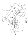
- FIG. 1 is a perspective view showing a puncture device to which a medical tube (medical tube assembly) according to a first embodiment of the present invention is applied.
- FIG. 2 is a side view of the puncture device shown in FIG.
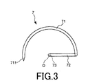
- FIG. 3 is a plan view showing an operation member of the puncture apparatus shown in FIG. 4A and 4B are diagrams showing a puncture member included in the puncture apparatus shown in FIG. 1, wherein FIG. 4A is a perspective view, and FIG. 4B is a cross-sectional view taken along line AA in FIG.
- FIG. 5 is a cross-sectional view of the puncture member shown in FIG. 6A and 6B are diagrams showing a state maintaining mechanism included in the puncture member shown in FIG. 4A, wherein FIG.
- FIG. 6A is a top view
- FIGS. 6B and 6C are cross-sectional views
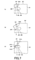
- FIG. 7 is a partially enlarged view showing a state maintaining mechanism of the puncture member shown in FIG. 3, wherein (a) and (b) are plan views showing modifications, and (c) is a plan view showing this embodiment.
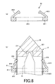
- It is. 8A and 8B are diagrams showing a second anchor included in the puncture device shown in FIG. 1, wherein FIG. 8A is a cross-sectional view and FIG. 8B is a cross-sectional view showing a state where the puncture member is engaged.
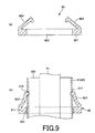
- FIG. 9 is a view showing a first anchor of the puncture device shown in FIG.
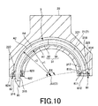
- FIG. 10 is a cross-sectional view showing a guide portion of a frame provided in the puncture apparatus shown in FIG.
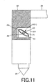
- FIG. 11 is a cross-sectional view showing a guide portion of a frame provided in the puncture apparatus shown in FIG.
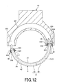
- FIG. 12 is a cross-sectional view showing a guide portion of a frame provided in the puncture apparatus shown in FIG.
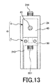
- FIG. 13 is a plan view showing a frame fixing portion provided in the puncture apparatus shown in FIG. 1.
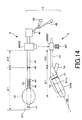
- FIG. 14 is a side view of an insertion tool included in the puncture device shown in FIG. 1.
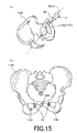
- FIG. 15 is a diagram showing a positional relationship between the puncture member and the closing hole (pelvis), in which (a) is a side view and (b) is a front view.
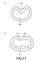
- 16 is a partially enlarged view of a vaginal insertion member included in the insertion tool shown in FIG. 17A is a cross-sectional view showing an example of the shape of the vagina wall
- FIG. 17B is a cross-sectional view showing a state where the vaginal insertion portion is inserted into the vagina shown in FIG.
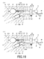
- FIG. 18 is a view showing an implant used together with the puncture device shown in FIG. 19 (a) and 19 (b) are diagrams for explaining the operation procedure of the puncture apparatus shown in FIG.
- FIGS. 26A and 26B are diagrams for explaining the operation procedure of the puncture apparatus shown in FIG.
- FIG. 27 is a perspective view showing a medical tube (medical tube assembly) according to a second embodiment of the present invention.
- FIG. 28 is a sectional view showing a modification of the medical tube (medical tube assembly) shown in FIG.
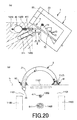
- FIG. 29 is a perspective view showing a medical tube (medical tube assembly) according to a third embodiment of the present invention.
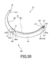
- FIG. 30 is a perspective view showing a medical tube (medical tube assembly) according to a fourth embodiment of the present invention.
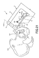
- FIG. 31 is a perspective view showing a medical tube (medical tube assembly) according to a fifth embodiment of the present invention.
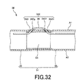
- FIG. 32 is a cross-sectional view showing a medical tube (medical tube assembly) according to a sixth embodiment of the present invention.
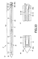
- FIG. 33 is a view showing a medical tube (medical tube assembly) according to a seventh embodiment of the present invention, in which (a) is a plan view, and (b) and (c) are sectional views.
- FIG. 34 is a cross-sectional view showing a medical tube (medical tube assembly) according to an eighth embodiment of the present invention.
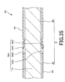
- FIG. 35 is a cross-sectional view showing a modification of the medical tube shown in FIG.
- FIG. 36 is a view showing a medical tube (medical tube assembly) according to a ninth embodiment of the present invention, in which (a) is a plan view, and (b) and (c) are sectional views.
- FIG. 1 is a perspective view showing a puncture device to which a medical tube (medical tube assembly) according to a first embodiment of the present invention is applied.
- FIG. 2 is a side view of the puncture device shown in FIG.
- FIG. 3 is a plan view showing an operation member of the puncture apparatus shown in FIG. 4A and 4B are diagrams showing a puncture member included in the puncture apparatus shown in FIG. 1, wherein FIG. 4A is a perspective view, and FIG. 4B is a cross-sectional view taken along line AA in FIG.
- FIG. 5 is a cross-sectional view of the puncture member shown in FIG. 6A and 6B are diagrams showing a state maintaining mechanism included in the puncture member shown in FIG.
- FIG. 6A is a top view
- FIGS. 6B and 6C are cross-sectional views.
- FIG. 7 is a partially enlarged view showing a state maintaining mechanism of the puncture member shown in FIG. 3, wherein (a) and (b) are plan views showing modifications, and (c) is a plan view showing this embodiment.
- It is. 8A and 8B are diagrams showing a second anchor included in the puncture device shown in FIG. 1, wherein FIG. 8A is a cross-sectional view and FIG. 8B is a cross-sectional view showing a state where the puncture member is engaged.
- FIG. 9 is a view showing a first anchor of the puncture device shown in FIG.
- FIG. 10 is a cross-sectional view showing a guide portion of a frame provided in the puncture apparatus shown in FIG.
- FIG. 11 is a cross-sectional view showing a guide portion of a frame provided in the puncture apparatus shown in FIG.
- FIG. 12 is a cross-sectional view showing a guide portion of a frame provided in the puncture apparatus shown in FIG.
- FIG. 13 is a plan view showing a frame fixing portion provided in the puncture apparatus shown in FIG. 1.
- FIG. 14 is a side view of an insertion tool included in the puncture device shown in FIG. 1.
- FIG. 15 is a diagram showing the positional relationship between the puncture member and the closing hole (pelvis), in which (a) is a side view and (b) is a front view.
- 16 is a partially enlarged view of a vaginal insertion member included in the insertion tool shown in FIG. 17A is a cross-sectional view showing an example of the shape of the vagina wall
- FIG. 17B is a cross-sectional view showing a state where the vaginal insertion portion is inserted into the vagina shown in FIG.
- FIG. 18 is a view showing an implant used together with the puncture device shown in FIG. 19 (a) and 19 (b) are diagrams for explaining the operation procedure of the puncture apparatus shown in FIG.
- FIGS. 26A and 26B are diagrams for explaining the operation procedure of the puncture apparatus shown in FIG.
- FIG. 2 shows a state that is not yet used. Hereinafter, for convenience of explanation, this state is also referred to as an “initial state”.
- the state where the puncture device (insertion tool) shown in FIG. 2 is attached to the patient is also referred to as “attached state”.
- the puncture member extending in an arc shape is illustrated as being linearly extended for convenience of explanation.
- Puncture device First, a puncture device to which the medical tube and medical tube assembly of the present invention are applied will be described.
- the puncture device 1 shown in FIG. 1 and FIG. 2 is a device used when embedding a living tissue supporting indwelling material for treatment of female urinary incontinence, that is, treatment of urinary incontinence.
- the puncture device 1 includes a frame (support portion) 2, a puncture member 3, a urethral insertion member 4, a vaginal insertion member 5, an operation member 7, and anchors 81 and 82.
- the member 4, the vaginal insertion member 5, the operation member 7, and the anchors 81 and 82 are supported.
- the urethral insertion member 4 and the vagina insertion member 5 constitute an insertion tool 6.
- the operation member 7 is a member for operating the puncture member 3. As shown in FIGS. 1 to 3, the operation member 7 has an insertion portion 71, a shaft portion 73, and a connecting portion 72 that connects the insertion portion 71 and the shaft portion 73.
- the insertion portion 71, the coupling portion 72, and the shaft portion 73 may be integrally formed, or at least one portion may be formed as a separate body from other portions.
- the insertion portion 71 is a part that is inserted into the puncture member 3 and functions as a stylet that reinforces the puncture member 3 from the inside.
- the puncture member 3 is connected to the operation member 7, whereby the operation member 7 can be operated by the operation member 7.
- Such an insertion portion 71 has an arc shape corresponding to the shape of the puncture member 3.
- the central angle of the insertion portion 71 is set according to the central angle of the puncture member 3.
- the distal end portion 711 of the insertion portion 71 is tapered. By having the tapered tip end portion 711, the puncture member 3 can be smoothly inserted into the insertion portion 71.
- the shaft portion 73 intersects the center O of the insertion portion 71 and extends along an axis J1 orthogonal to the plane f1 including the insertion portion 71.
- the connecting portion 72 connects the proximal end portion of the insertion portion 71 and the distal end portion of the shaft portion 73. Moreover, the connection part 72 has comprised the substantially L shape bent in the substantially right angle in the middle. The connecting portion 72 also functions as a grasping portion that the operator grasps when operating the operation member 7.
- Such an operation member 7 is configured to have higher rigidity than the puncture member 3 (main body 31).
- the constituent material of the operation member 7 is not particularly limited, and for example, various metal materials such as stainless steel, aluminum or aluminum alloy, titanium or titanium alloy can be used.
- the puncture member 3 is a member for puncturing a living body.
- the puncture member 3 has a long sheath (medical tube) 30 and a needle body 35 provided at the distal end of the sheath 30 as shown in FIG.
- the sheath 30 includes a tubular main body 31 and a state maintaining mechanism 34.
- the main body 31 is composed of a long tubular body (tube), and the distal end and the proximal end are open. Such a main body 31 has an internal space into which an implant main body (strip-shaped elongated object) 91 can be inserted.
- the main body 31 has a curved shape curved in an arc shape, and has a flat cross-sectional shape as shown in FIG.
- the cross-sectional shape at the central portion S4 in the longitudinal direction of the main body 31 is a flat shape including the short axis J31 and the long axis J32.
- an implant main body 91 is disposed in the main body 31.
- the posture within the main body 31 of the implant main body 91 can be controlled by making the main body 31 into a flat shape.
- the width of the internal space of the main body 31 is designed to be substantially the same as the width of a main body portion 911 described later of the implant main body 91.
- the flat shape of the main body 31 is not particularly limited, and for example, an oval shape, a convex lens shape in cross section, a rhombus with rounded corners, a rectangle with rounded corners (flat shape), and a central portion at both ends It can also be a spindle shape that is larger (expanded) than the portion.
- the end located on the inner side in the long axis direction is also referred to as “inner peripheral part A1”, and the end located on the outer side is also referred to as “outer peripheral part A2”.
- the surface facing upward is also referred to as “front surface A3”, and the surface facing downward is also referred to as “back surface A4”.
- a plane including both the center point of the arc of the central portion S4 and the center point of the cross-sectional shape with respect to the longitudinal direction of the main body 31 is defined as a plane f9.
- the angle formed between the plane f9 and the short axis J31 at the central portion S4 is defined as an inclination angle ⁇ 1
- the inclination angle ⁇ 1 is preferably an acute angle.
- the inclination angle ⁇ 1 is not particularly limited as long as it is an acute angle, but is preferably about 20 to 60 °, more preferably 30 to 45 °, and still more preferably about 35 to 40 °. . Thereby, the effect mentioned above improves further.
- the inclination angle ⁇ 1 preferably satisfies the above numerical range over the entire extending direction of the main body 31, but at least satisfies the above numerical range at the central portion S4 in the extending direction of the main body 31.
- the above effects can be exhibited.
- the “central portion S4” means at least a region including a portion located between the urethra and the vagina in a state where the puncture member 3 is punctured into the living body (a state where the main body 31 is disposed in the living body). .
- the center part (center and the vicinity of both sides) between the anchors 81 and 82 is the center part S4 in a state where the anchors 81 and 82 are engaged with the puncture member 3 as described later. .
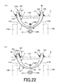
- markers are provided at both ends of the main body 31 at positions that are equal from the central portion S4 and project outside the living body in a state where the main body 31 is disposed on the living body (state shown in FIG. 22). Also good. Thereby, the position in the living body of center part S4 can be confirmed by comparing the position of both markers.
- the configuration of the main body 31 can be rephrased as follows. That is, as shown in FIG. 4B, the main body 31 is formed such that the major axis J32 is inclined with respect to the arc central axis J5, and an extension line J32 between the arc central axis J5 and the major axis J32. It can be said that 'is configured to have an intersection P. In this case, the angle ⁇ 5 formed by the central axis J5 and the extension line J32 ′ is equal to the inclination angle ⁇ 1. In other words, as shown in FIG.
- the main body 31 is an inner peripheral portion having a minimum radius of curvature r ⁇ b> 1 located at the inner peripheral edge in a plan view when viewed from the central axis J ⁇ b> 5 direction of the main body 31.
- Such a main body 31 is composed of two divided pieces so that it can be divided along the way. That is, the main body 31 is divided into a distal end divided piece 32 and a proximal end divided piece 33.
- the distal end divided piece 32 and the proximal end divided piece 33 have substantially the same length, and their boundary is located at the central portion S4.
- the distal end divided piece 32 has a tube shape and has a distal end side opening 321 and a proximal end side opening 322.
- the base end split piece 33 also has a tube shape and has a front end side opening 331 and a base end side opening 332. And the front-end
- the split pieces 32 and 33 may be connected by inserting the tip split piece 32 into the base end split piece 33.
- the connection state in which the divided pieces 32 and 33 are connected is maintained by the state maintaining mechanism 34.
- the state maintaining mechanism 34 exposes the holes 342a, 342b, 342c, an endless thread (connecting member) 341 inserted through the holes 342a, 342b, 342c, and the thread 341. Exposure holes (through holes) 345 and 346 to be exposed, and slits 347 connecting the exposure holes 345 and 346.
- the hole 342a is a base end portion of the base end split piece 33 and is provided near the inner peripheral portion A1 of the surface A3.
- the holes 342b and 342c are the base end portions of the tip split piece 32, and are provided facing the inner peripheral portion A1 of the front surface A3 and the back surface A4.
- the yarn 341 is disposed in the main body 31 and is exposed to the outside of the main body 31 between the hole 342b and the hole 342c and between the hole 342a and the proximal end opening 332.
- the yarn 341 is disposed in the main body 31 and is exposed to the outside of the main body 31 between the hole 342b and the hole 342c and between the hole 342a and the proximal end opening 332.
- the thread 341 is also disposed closer to the inner peripheral portion A1. Therefore, when the implant main body 91 is inserted into the main body 31, the thread 341 is hardly caught on the implant main body 91.
- the thread 341 is prepared, for example, as a thread with ends, and one end of the thread 341 is inserted into the main body 31 from the proximal end opening 332, pulled out of the main body 31 from the hole 342b, and inserted into the main body 31 from the hole 342c. It is obtained by pulling it out of the main body 31 from the hole 342a and finally tying it with the other end in the vicinity of the base end side opening 332.
- the position of the knot is not limited.
- the hole 342a has an axis inclined so that the outer opening is located closer to the base end side than the inner opening.
- the holes 342b and 342c each have an inclined axis so that the outer opening is located at the tip of the inner opening.
- the exposure holes 345 and 346 are provided to face the front surface A3 and the back surface A4 of the base end portion of the base end split piece 33, respectively.
- part in which the exposure holes 345 and 346 are provided protrudes from the body surface in the state which has arrange
- the exposure holes 345 and 346 are located on the path of the yarn 341. Therefore, the thread 341 is exposed outside the main body 31 from the exposure holes 345 and 346. Further, the exposure holes 345 and 346 are connected by a slit 347 provided in the inner peripheral portion A1 along the circumferential direction of the main body 31.
- the thread 341 can be easily cut by providing the exposure holes 345 and 346 and the slit 347 as in the present embodiment.
- a scissors having a pair of blades first blade and second blade
- the first blade is inserted into the exposure holes 345 and 346
- the thread 341 is positioned between the pair of blades.
- the heel is closed, at least one of the first and second blades passes through the slit 347, the first and second blades overlap each other, and the thread 341 is cut in the process.
- the thread 341 can be easily cut.
- the slit 347 is provided, and the slit 347 is used as a passage path of the blade. Thereby, the deformation of the main body 31 due to the tension of the yarn 341 is prevented.
- the passage route of the blade may be replaced by a slit 347 and configured by a hole 348.
- the hole 348 may be buckled and crushed by the tension of the thread 341, and the main body 31 may be deformed.
- the slit 347 since the portions 347a and 347b sandwiching the slit 347 are in contact and stretched, as shown in FIG. 7C, the above-described deformation does not occur and the main body 31 is not deformed. Is prevented.
- a pair of engagement holes 315 and 316 that engage with the anchor 81 are provided at the distal end portion of the main body 31.
- a pair of engagement holes 317 and 318 that engage with the anchor 82 are provided at the base end portion of the main body 31.
- the engagement holes 315 and 317 are provided in the inner peripheral portion A1
- the engagement holes 316 and 318 are provided in the outer peripheral portion A2.
- the main body 31 has a flat shape and is not easily crushed in the long axis direction, so that the separation distance between the inner peripheral portion A1 and the outer peripheral portion A2 is difficult to change. Further, the inner peripheral portion A1 and the outer peripheral portion A2 have large curvatures and are not easily deformed compared to the front surface A3 and the rear surface A4. Therefore, by providing the engagement holes 315 and 317 in the inner peripheral portion A1 and the engagement holes 316 and 318 in the outer peripheral portion A2, the engagement between the anchors 81 and 82 and the main body 31 is difficult to be released.
- the separation distance between the engagement holes 315 and 316 and the central portion S4 is substantially equal to the separation distance between the engagement holes 317 and 318 and the central portion S4.
- a needle body 35 is provided at the tip of the main body 31 as described above.
- the needle body 35 has a tapered needle tip 351 and a proximal end portion 352 provided on the proximal end side of the needle tip 351. Then, the base end portion 352 is inserted into the main body 31, whereby the needle body 35 is detachably held on the main body 31. Note that the base end portion 352 is fitted into the main body 31 with a force that can prevent unintentional detachment of the needle body 35 from the main body 31.
- the needle body 35 may be configured integrally with the main body 31.
- the base end portion 352 is provided with an engaging portion 353 that engages with the distal end portion 711 of the insertion portion 71.
- the engaging portion 353 is configured by a concave portion, and the distal end portion 711 is positioned in the engaging portion 353 in the inserted state in which the puncture member 3 is inserted into the inserting portion 71.
- the puncture member 3 has been described above.
- the central angle ⁇ 4 (see FIG. 10) of the puncture member 3 is not particularly limited, and is appropriately set according to various conditions.
- the needle body 35 is attached to one of the patient's buttocks. It is set so that it can enter the body, pass between the urethra and vagina, and protrude from the other buttocks.
- the central angle ⁇ 4 is preferably 150 to 270 °, more preferably 170 to 250 °, and further preferably 190 to 230 °.
- a hard material that maintains the shape and internal space in a state of being inserted into the body is preferable.
- a hard material include various resin materials such as polyethylene, polyimide, polyamide, polyester elastomer, and polypropylene, and various metal materials such as stainless steel, aluminum or aluminum alloy, titanium or titanium alloy, and the like.
- the wall can be reinforced by a reinforcing member.
- the shape and the internal space can be maintained while being inserted into the body.
- the reinforcing member by embedding a spiral object in the wall of the main body 31, it is possible to provide flexibility while maintaining the internal space to the extent that the insert can slide.
- the main body 31 has light permeability and the inside can be visually recognized from the outside. Thereby, for example, it is possible to confirm whether the distal end portion 711 of the insertion portion 71 inserted inside is engaged with the engagement portion 353 or whether the thread 341 is not cut.
- the puncture member 3 (main body 31) described above and the insertion portion 71 inserted into the main body 31 constitute the medical tube assembly 10, and in the puncture device 1, these are in the state of the medical tube assembly 10. Use begins.
- the number and arrangement of the holes (342a, 342b, 342c) through which the thread 341 passes are not particularly limited as long as the connection state between the tip split piece 32 and the base end split piece 33 can be maintained by the thread 341.
- yarn 341 does not need to be endless shape, and the end shape which has one end and the other end may be sufficient as it.
- an end-shaped thread may be prepared, and one end thereof may be a loop that passes through the hole 342a and the proximal end opening 332, and the other end may be a loop that passes through the holes 342b and 342c.
- the thread 341 includes a string, a band, and the like that can be used in the same manner as the thread 341.
- the anchor (second anchor) 81 protrudes from the base 811 having an insertion hole 812 through which the main body 31 is inserted, and engages with the pair of engagement holes 315 and 316.
- a pair of claw portions 813 and 814 is provided.
- the cross-sectional shape of the insertion hole 812 corresponds to the cross-sectional shape of the main body 31. Therefore, in a state where the puncture member 3 is inserted through the insertion hole 812, the rotation of the anchor 81 with respect to the puncture member 3 is restricted, and these positional relationships are appropriately maintained.
- the claw portions 813 and 814 engage with the engagement holes 315 and 316 as shown in FIG.
- the anchor 81 is engaged with the tip split piece 32.
- the base portion 811 is located on the proximal end side with respect to the claw portions 813 and 814.
- the anchor (first anchor) 82 includes a base portion 821 having an insertion hole 822 through which the main body 31 is inserted, a base portion 821, and a pair of engagement holes 317, 318. It has a pair of claw parts 823 and 824 to be engaged.
- the cross-sectional shape of the insertion hole 822 corresponds to the cross-sectional shape of the main body 31. Therefore, in a state where the puncture member 3 is inserted through the insertion hole 822, the rotation of the anchor 82 with respect to the puncture member 3 is restricted, and these positional relationships are appropriately maintained.
- the constituent materials of the anchors 81 and 82 are not particularly limited, and various resin materials can be used, for example.
- the frame 2 rotatably holds the operation member 7 to which the puncture member 3 is attached, and fixes the insertion tool 6 and the anchors 81 and 82 in a detachable manner.
- the frame 2 has a function of determining a puncture route of the needle body 35 when the puncture member 3 punctures a living tissue.
- the frame 2 is configured so that when the puncture member 3 punctures a living tissue, the needle body 35 passes between the urethra insertion member 4 and the vagina insertion member 5 without colliding with them. 3.
- the positional relationship between the urethral insertion member 4 and the vaginal insertion member 5 is defined.
- the frame 2 guides the bearing portion 21 that supports the shaft portion 73 of the operation member 7 and the puncture member 3 and detachably holds the first and second anchors 81 and 82.
- a guide portion (holding portion) 22 a connecting portion 23 that connects the bearing portion 21 and the guide portion 22, and a fixing portion 24 to which the insertion tool 6 is fixed.
- the bearing portion 21 is located on the proximal end side of the puncture device 1 and extends in a direction substantially orthogonal to the axis J1.
- a through hole 211 is formed on the shaft J1 of the bearing portion 21, and the shaft portion 73 is rotatably inserted into the through hole 211.
- the operation member 7 is supported on the frame 2 in a state of being rotatable about the axis J1.
- the guide portion 22 is located on the distal end side of the puncture device 1 and is disposed to face the bearing portion 21. As shown in FIG. 10, the guide portion 22 is formed with a substantially C-shaped guide groove 221 that accommodates the puncture member 3 and guides the puncture member 3. Further, as shown in FIG. 11, in the state of being placed in the guide groove 221, the puncture member 3 has the back surface A4 positioned on the distal end side and the surface A3 positioned on the proximal end side.
- the guide part 22 is holding the anchors 81 and 82 so that attachment or detachment is possible.
- the anchor 82 is held facing the front end side opening 222 so that the insertion hole 822 is continuous with the guide groove 221, and the anchor 81 is guided by the guide groove 221 so that the insertion hole 812 is continuous with the guide groove 221. Is held opposite to the base end side opening 223.
- the main body 31 is inserted into the insertion hole 822 of the anchor 82, and the needle body 35 projects from the guide portion 22.
- the puncture member 3 gradually protrudes from the guide portion 22, and finally, the needle body 35 enters the guide portion 22 through the proximal end opening 223 as shown in FIG. .
- the puncture member 3 passes through the insertion hole 812 of the anchor 81 on the distal end side of the puncture member 3, and the claw portions 813 and 814 engage with the engagement holes 315 and 316.
- the claw portions 823 and 824 are engaged with the engagement holes 317 and 318 on the proximal end side of the puncture member 3.
- the anchors 81 and 82 are engaged with the puncture member 3.
- the claw portions 813 and 814 of the anchor 81 are inclined toward the front side in the moving direction of the puncture member 3. Therefore, when the puncture member 3 is inserted into the anchor 81, the claw portions 813 and 814 and the puncture member 3 are prevented from being caught, and the puncture member 3 slides between the claw portions 813 and 814 while smoothly moving between them. Can be moved to.
- the direction of the anchor 82 is not particularly limited, and the claw portions 813 and 814 may face the rear side in the moving direction of the puncture member 3, contrary to the present embodiment.
- the connecting portion 23 connects the bearing portion 21 and the guide portion 22. Further, the connecting portion 23 has a rod shape extending substantially parallel to the axis J1. The connecting portion 23 also functions as a grasping portion, and an operator can use the puncture apparatus 1 by grasping the connecting portion 23.
- the fixing part 24 is arranged to face the connecting part 23 via the axis J1. As shown in FIG. 13, the fixing portion 24 has a concave portion 243 into which a support portion 60 described later of the insertion tool 6 is fitted, and a male screw 244. The insertion tool 6 can be fixed to the fixing portion 24 by fitting the supporting portion 60 into the recess 243 and further tightening the male screw 244 into a female screw (not shown) of the supporting portion 60.
- the insertion tool 6 includes a urethral insertion portion (second insertion portion) 41 to be inserted into the urethra, and a vaginal insertion portion (first insertion portion) 51 to be inserted into the vagina. And a support portion 60 that supports the urethral insertion portion 41 and the vaginal insertion portion 51.
- the insertion tool 6 includes the urethral insertion member 4 and the vaginal insertion member 5, the urethral insertion member 4 includes the urethral insertion portion 41, and the vaginal insertion member 5 includes the vaginal insertion portion 51.
- the support portion 60 includes a support portion 40 that is provided in the urethral insertion member 4 and supports the urethral insertion portion 41, and a support portion 50 that is provided in the vaginal insertion member 5 and supports the vaginal insertion portion 51.
- the urethral insertion member 4 and the vagina insertion member 5 are detachable via the support portions 40 and 50.
- the urethral insertion member 4 and the vaginal insertion member 5 will be described in order.
- the urethral insertion member 4 has a long urethral insertion portion 41 that is inserted into the urethra halfway and a support portion 40 that supports the urethral insertion portion 41.
- a portion located in the urethra (including the bladder) in the attached state is also referred to as an “insertion portion 411”, and is a portion exposed outside the body from the urethral opening in the attached state.
- a portion up to the support portion 40 is also referred to as a “non-insertion portion 412”.
- the urethra insertion part 41 has a straight tubular shape with a rounded tip.
- a balloon 42 that can be expanded / contracted and a urine discharge portion 47 are provided at the distal end portion of the insertion portion 411.
- the balloon 42 functions as a restricting portion that restricts the axial position of the urethral insertion member 4 in the urethra.
- the puncture device 1 when used, the balloon 42 is expanded after being inserted into the patient's bladder. And the position of the urethral insertion member 4 with respect to a bladder and a urethra is fixed by the expanded balloon 42 being caught in a bladder neck.
- the urine discharge unit 47 is used to discharge urine in the bladder.
- the balloon 42 passes through the urethra insertion part 41 and is connected to a balloon port 43 provided at the base end thereof.
- a balloon expansion device such as a syringe can be connected to the balloon port 43.
- the working fluid liquid such as physiological saline, gas, etc.
- the balloon 42 expands.
- the working fluid is extracted from the balloon 42 by the balloon expanding device, the balloon 42 contracts.
- FIG. 14 the state in which the balloon 42 is deflated is indicated by a two-dot chain line, and the state in which the balloon 42 is expanded is indicated by a solid line.
- the urine discharge part 47 is provided with a discharge hole 471 that communicates the inside and outside of the urine discharge part 47.
- the urine discharge part 47 passes through the urethra insertion part 41 and is connected to a urine discharge port 48 provided at the base end part thereof. Therefore, urine introduced from the discharge hole 471 can be discharged from the urine discharge port 48.
- These balloon 42 and urine discharge part 47 can be constituted by a double lumen, for example.
- a plurality of suction holes 44 are formed in the middle of the insertion portion 411.
- the plurality of suction holes 44 are arranged over the entire area in the circumferential direction of the urethral insertion portion 41.
- Each suction hole 44 is connected to a suction port 45 provided at the base end portion through the urethral insertion portion 41.
- a suction device such as a pump can be connected to the suction port 45.
- the number of suction holes 44 is not particularly limited, and may be one, for example.
- the arrangement of the suction holes 44 is not particularly limited, and may be formed only in a part of the circumferential direction of the urethral insertion portion 41, for example.
- a marker 46 for confirming the insertion depth of the urethra insertion part 41 into the urethra is provided at the boundary between the insertion part 411 and the non-insertion part 412.
- the marker 46 is located at the urethral opening when the urethral insertion portion 41 is inserted into the urethra and the balloon 42 is located in the bladder. Thereby, the insertion depth to the urethra of the insertion part 411 can be confirmed easily.
- the marker 46 only needs to be visually recognized from the outside, and can be constituted by, for example, a colored portion, an uneven portion, or the like. In addition, it may replace with the marker 46 and may provide the scale in which the distance from the front-end
- the length of the insertion portion 411 is not particularly limited, and is appropriately set depending on the length of the patient's urethra, the shape of the bladder, and the like. Since the length of a typical female urethra is about 30 to 50 mm, it is more preferably about 50 to 100 mm.
- the length of the non-insertion portion 412 (the separation distance between the urethral opening and the support portion 40) is not particularly limited, but is preferably about 100 mm or less, and more preferably about 20 to 50 mm. Thereby, the non-insertion part 412 can be made into appropriate length, and operativity improves. If the length of the non-insertion portion 412 exceeds the upper limit, depending on the configuration of the frame 2, the center of gravity of the puncture device 1 is greatly separated from the patient, and the stability of the puncture device 1 in the worn state is reduced. There is a case.
- the constituent material of the urethral insertion member 4 is not particularly limited, and for example, various metal materials such as stainless steel, aluminum or aluminum alloy, titanium or titanium alloy, and various resin materials can be used.
- the inclination angle ⁇ 2 of the plane f9 (plane f1) with respect to the plane f2 orthogonal to the axis J2 of the urethra insertion part 41 is preferably about 20 to 60 °, more preferably about 30 to 45 °, More preferably, it is about 35 to 40 °.
- the main body 31 is preferably placed in the body so that the angle between the plane f9 and the plane orthogonal to the axis of the urethra is about 20 to 60 °, and the body 31 is about 30 to 45 °. It is more preferable to be indwelled in the body, and it is more preferable to be indwelled in the body so as to be about 35 to 40 °. Thereby, the puncture of the puncture member 3 can be easily performed, and the puncture distance by the puncture member 3 can be further shortened.
- the puncture member 3 can broadly grasp the left and right closure holes 1101 and 1102 of the pelvis 1100 in a plane as shown in FIG. It is possible to secure a wide puncture space for the puncture member 3. That is, the puncture member 3 can be punctured in a relatively vertical direction with respect to the closing holes 1101 and 1102 in a state where the patient is in a predetermined body position (crushed stone position). Therefore, the puncture member 3 can be punctured easily. In addition, since the puncture member 3 is punctured in a relatively vertical direction with respect to the closure holes 1101 and 1102, the needle body 35 of the puncture member 3 passes through the shallow portion of the tissue.
- the puncture member 3 can pass through the closure holes 1101 and 1102 near the pubic joint 1200, preferably through the safety zone S5. Since the safety zone S5 is a site where there are few nerves and blood vessels to avoid damage, the puncture member 3 can be punctured safely. Therefore, it becomes less invasive and can reduce the burden on the patient. As described above, by setting the inclination angle ⁇ 2 within the above range, the patient can puncture the puncture member 3 more appropriately. In addition, puncturing at the above-described angle makes it easy to target the tissue between the middle urethra and the vagina that indicate the middle portion in the length direction of the urethra. Between the middle urethra and the vagina is a position suitable as a site for implanting the implant 9 and treating urinary incontinence.
- the puncture member 3 planarly closes the closing holes 1101 and 1102 depending on individual differences in the patient, the posture during the procedure, and the like. There are cases where it is not possible to capture widely or the puncture route cannot be shortened sufficiently.
- the puncture between the middle urethra and the vagina is facilitated by puncturing the urethra or the vagina, and both the urethra and the vagina in a position shifted so as to be pushed into the body.
- the urethra insertion member 4 and / or the vagina insertion member 5 is inserted in an appropriate position, and a suction hole 44, which will be described later, is provided in the urethra and the vagina.
- the urethral insertion member 4 and / or the vagina insertion member 5 can be further moved to the inside of the body along the respective axes to a predetermined position.
- the main body 31 is punctured perpendicularly to the left and right closure holes 1101 and 1102 of the pelvis in a state where the position is shifted so as to push at least one of the urethra and the vagina into the inside of the body.
- the passage can be formed at a position suitable for the above.
- the trajectory of the main body 31 is set so as to pass through the safety zones S5 of the left and right closure holes 1101 and 1102 of the pelvis, and at least one of the urethra and vagina is inward of the body so that the trajectory is located between the middle urethra and the vagina. It is preferable to shift and puncture the main body 31 along the track to form a passage.
- the vaginal insertion member 5 includes a long vaginal insertion portion (first insertion portion) 51 that is inserted into the vagina partway and a support portion that supports the vaginal insertion portion 51. 50.
- first insertion portion a portion located in the vagina in the wearing state
- insertion portion 511 a portion located in the vagina in the wearing state
- non-insertion portion 512 a portion exposed from the vaginal opening to the outside of the body in the wearing state up to the support portion 50. This portion is also referred to as “non-insertion portion 512”.
- the insertion portion 511 has a long shape. Further, the insertion portion 511 extends with an inclination with respect to the insertion portion 411 so that the distal end side is separated from the insertion portion 411. By tilting the insertion portion 511 with respect to the insertion portion 411, the positional relationship between the insertion portions 411 and 511 can be made closer to the positional relationship between the urethra and the vagina than when the insertion portion 511 is not tilted. Therefore, the puncture device 1 is more stably held by the patient in the wearing state, and the burden on the patient is reduced.
- the inclination angle ⁇ 3 of the insertion portion 511 with respect to the insertion portion 411 is not particularly limited, but is preferably about 0 to 45 °, and more preferably about 0 to 30 °. Thereby, the said effect can be exhibited more notably.
- the inclination angle ⁇ 3 is less than the above lower limit value or exceeds the above upper limit value, the vagina and urethra deform unnaturally in the wearing state depending on individual differences of patients, posture during the procedure, etc.
- the puncture device 1 may not be stably held.
- the insertion portion 511 has a flat shape that is crushed in the vertical direction of the puncture device 1 (the arrangement direction of the urethra and vagina). Further, the insertion portion 511 has a central portion having a substantially constant width and a rounded tip portion.
- the length L2 of the insertion portion 511 is not particularly limited, but is preferably about 20 to 100 mm, and more preferably about 30 to 60 mm.
- the width W1 of the insertion portion 511 is not particularly limited, but is preferably about 10 to 40 mm, more preferably about 20 to 30 mm.
- the thickness of the insertion portion 511 is not particularly limited, but is preferably about 5 to 25 mm, and more preferably about 10 to 20 mm. By adopting such length ⁇ width ⁇ thickness, the insertion portion 511 has a shape and size suitable for a general vagina. Therefore, the stability of the puncture device 1 in the mounted state is increased, and the burden on the patient is reduced.
- a plurality of bottomed recesses 53 are formed on the upper surface (surface on the urethral insertion portion 41 side) 511a of the insertion portion 511.
- the number of the recessed parts 53 is not specifically limited, For example, one may be sufficient.
- one suction hole 59 is provided on the bottom surface of each recess 53, and each suction hole 59 passes through the insertion portion 511 and is connected to a suction port 54 provided at the base end portion thereof. .
- the suction port 54 is provided so as to be located outside the living body in the mounted state.
- a suction device such as a pump can be connected to the suction port 54.
- the front wall of the vagina which is the upper surface of the vagina wall, is inserted into the insertion portion 511. Adsorbed and fixed.
- the vagina insertion portion 51 is pushed into the distal end (inside the body) with the vagina wall being adsorbed and fixed, the vagina wall can be pushed together with this. Therefore, the arrangement and shape of the vagina wall can be adjusted, the puncture route of the puncture member 3 can be secured, and the puncture of the puncture member 3 can be performed accurately and safely.
- the region S2 in which the plurality of recesses 53 are formed is disposed to face the region S1. And the needle point of the puncture member 3 passes between these area
- the urethra posterior wall which is the lower surface of the urethra wall, is adsorbed by the insertion portion 411 in the region S1, and the vagina front wall is adsorbed by the insertion portion 511 in the region S2.
- the wall and vaginal wall are more widely separated. Therefore, the puncture member 3 can be punctured more safely by passing the puncture member 3 through such a region.
- the region S2 extends over substantially the entire width direction of the upper surface 511a.
- the width W2 of the region S2 is not particularly limited, but is preferably about 9 to 39 mm, and more preferably about 19 to 29 mm.
- the vaginal wall can be more reliably adsorbed to the insertion portion 511 without being greatly affected by the shape of the vagina wall.
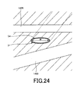
- some patients may have a vagina 1400 having a shape in which a part of the anterior vaginal wall 1410 hangs into the vagina. Even in such a case, if the width W2 is set as described above, as shown in FIG.
- the front wall of the vagina can be more reliably separated from the urethra without being affected by the shape of the vagina.
- the front wall of the vagina can be adsorbed so as to be further away from the urethra, and the living tissue between the urethra wall and the vagina wall is more widely spread. be able to.
- the insertion unit 511 is provided with a marker (puncture position confirmation unit) 57 that can confirm the puncture route of the puncture device 1, that is, the vaginal wall present on the upper surface of the position where the marker 57 exists.
- the puncture device can be fixed to puncture between the urethral walls. Therefore, the operability and safety of the insertion tool 6 are improved.
- the marker 57 is provided at least on the lower surface 511b of the insertion portion 511. Since the lower surface 511b is a surface that faces the vaginal opening side and is visible to the operator through the vaginal opening in the inserted state, by providing the marker 57 on the lower surface 511b, the puncture route of the puncture apparatus 1 can be more reliably performed. Can be confirmed. Further, the insertion depth of the insertion portion 511 into the vagina can also be confirmed.
- the marker 57 only needs to be visible from the outside, and can be configured by, for example, a colored portion, an uneven portion, or the like.
- the non-insertion portion 512 has a thin rod shape extending substantially parallel to the urethral insertion portion 41.
- the separation distance D between the non-insertion portion 512 and the urethral insertion portion 41 is not particularly limited, but is preferably about 10 to 40 mm in accordance with the separation distance between the urethral opening and the vaginal opening in a general woman. .
- the length of the non-insertion portion 512 (the distance between the vaginal opening and the support portion 50) is not particularly limited, but is preferably about 100 mm or less, and more preferably about 20 to 50 mm. Thereby, the non-insertion part 512 can be made into suitable length, and operativity improves. If the length of the non-insertion portion 512 exceeds the above upper limit value, the center of gravity of the puncture device 1 is greatly separated from the patient depending on the configuration of the frame 2 and the stability of the puncture device 1 in the worn state is lowered. There is a case.
- the support portion 50 is provided with a male screw 501, and the support portions 40 and 50 are fixed to each other by tightening the male screw 501 into a female screw (not shown) of the support portion 40.
- the constituent material of the vaginal insertion member 5 is not particularly limited.
- various metal materials such as stainless steel, aluminum or aluminum alloy, titanium or titanium alloy, and various resin materials are used. Can do.
- the configuration of the puncture device 1 has been described above.
- the urethral insertion member 4 and the vagina insertion member 5 constituting the insertion tool 6 are configured to be detachable.
- the present invention is not limited to this, and the urethral insertion member 4 and the vagina insertion member 5 are detachable. It may be impossible.
- the urethral insertion portion 41 is fixed to the support portion 40, but the present invention is not limited to this, and the urethral insertion portion 41 is fixed to the support portion 40 and the support portion 40. It may be possible to select a state in which it can slide in the axial direction. Specifically, for example, if the screw provided in the support part 40 is loosened, the urethra insertion part 41 becomes slidable with respect to the support part 40, and if the screw is tightened, the urethra insertion part 41 becomes the support part. 40 may be in a fixed state. According to this configuration, since the length of the non-insertion portion 412 can be adjusted, the insertion tool 6 is more convenient to use. This also applies to the vaginal insertion portion 51.
- each part is fixed to the frame 2 so that the inclination angle ⁇ 2 is constant, but the present invention is not limited to this, and the inclination angle ⁇ 2 may be variable.
- inclination-angle (theta) 2 can be adjusted according to a patient, it becomes the puncture apparatus 1 which is more convenient.
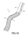
- the implant (living tissue support indwelling product) 9 shown in FIG. 18 is an implantable device for treating female urinary incontinence, that is, a device that supports the urethra, for example, the urethra is about to move to the vaginal wall side. Sometimes it is a device that supports the urethra so as to restrict its movement away from the vaginal wall. As this implant 9, for example, a long object having flexibility can be used.
- the implant 9 has an implant main body 91 and a bag-shaped packaging material 92 that accommodates the implant main body 91.
- the implant body 91 has a body portion 911 and a band 912 connected to one end of the body portion 911.
- contamination of the implant body 91 can be effectively prevented.
- a guide wire, string, thread, or the like may be used instead of the band 912.
- the main body portion 911 has a net shape, and the entire shape is a belt shape.
- the main-body part 911 can be comprised, for example by what crossed the linear body and knit in the net shape, ie, a net-like braided body.
- Examples of the linear body include a circular cross section, a flat cross section, that is, a strip.
- the constituent materials of the main body 911, the band 912, and the packaging material 92 are not particularly limited.
- various resin materials, fibers, and the like having biocompatibility such as polypropylene, polyester, and nylon can be used. .
- the implant 9 is not limited to the net-like one as long as the same effect can be exhibited.
- the patient is crushed on the operating table, and the insertion tool 6 is attached to the patient as shown in FIG. Specifically, first, the urethral insertion portion 41 of the urethral insertion member 4 is inserted into the urethra 1300 of the patient. At this time, the insertion depth is confirmed by the marker 46, and the balloon 42 is placed in the bladder 1310.
- the urethra 1300 is corrected to the predetermined shape by the urethra insertion part 41 having a predetermined shape. In the case of the present embodiment, the urethra is straightened by the straight urethra insertion part 41.
- the balloon 42 is expanded, and urine is discharged from the bladder 1310 through the discharge hole 471 as necessary. Further, the vaginal insertion part 51 of the vaginal insertion member 5 is inserted into the patient's vagina 1400. At this time, the insertion depth is confirmed with the marker 57 and inserted to an appropriate depth. Then, the support portions 40 and 50 are fixed by operating the male screw 501. Thereby, mounting
- the living body between the urethra and the vagina is determined from the body surface between the urethra and the vagina.
- a space S3 for piercing the tissue with the syringe is formed.
- a suction device is connected to the suction ports 45 and 54, the suction device is operated, the rear wall of the urethra is adsorbed to the urethral insertion portion 41, and the front wall of the vagina is adsorbed to the vaginal insertion portion 51.
- the suction hole 44 is blocked by the urethra wall, so that suction from the suction port 45 is stopped or weakened.
- the suction hole 59 is blocked by the vagina wall, so that suction from the suction port 54 is stopped or weakened.
- the insertion tool 6 may have a confirmation mechanism that mechanically confirms the suction state.
- the confirmation mechanism is not particularly limited as long as the adsorption state can be confirmed.
- the confirmation mechanism is based on a flow rate measurement unit (negative pressure gauge) that measures a flow rate from the suction port 54 and a measurement result from the flow rate measurement unit. It can be set as the structure which has a judgment part which judges whether adsorption
- liquid peeling is performed. Specifically, as shown in FIG. 19B, the puncture needle of the syringe 2000 is punctured into the vaginal front wall 1410 through the space (space S3) between the insertion portion 511 and the vaginal front wall 1410, and the urethra.
- a liquid such as physiological saline or a local anesthetic is injected into the living tissue between 1300 and the vagina 1400 (between the regions S1 and S2).
- the living tissue between the regions S1 and S2 expands, the urethral posterior wall is pressed against the urethral insertion portion 41, and the vagina front wall is pressed against the vagina insertion portion 51.
- the suction from the suction holes 44 and 59 it is preferable to continue the suction from the suction holes 44 and 59 even during the liquid peeling.
- the rear wall of the urethra is pressed against the urethra insertion part 41 by liquid peeling, the rear wall of the urethra is further adsorbed by the urethra insertion part 41, so that suction from the suction port 45 is stopped or weakened.
- the anterior vagina wall is pressed against the vagina insertion portion 51, the anterior vagina wall is further adsorbed by the vagina insertion portion 51, so that suction from the suction port 45 is stopped or weakened. Therefore, the operator can confirm whether or not the liquid separation has been properly performed based on the suction state from the suction ports 45 and 54.
- the frame 2 After performing liquid exfoliation and making the urethra posterior wall and the vagina anterior wall sufficiently separated, the frame 2 is fixed to the insertion tool 6 as shown in FIG. Thereby, the puncture apparatus 1 will be in the state with which the patient was mounted
- the connecting portion 72 of the operating member 7 is held with the other hand, and the operating member 7 is held back as shown in FIG. Rotate clockwise.
- the needle body 35 of the puncture member 3 punctures the body surface H of the right buttocks of the patient or a portion in the vicinity thereof (first portion) and enters the body, and the one closed hole 1101, the urethra 1300 and the vagina After passing through the other closing hole 1102 in order with the 1400, it projects out of the body surface H of the left buttocks or its vicinity (second part) and finally retracts into the guide part 22. (See FIG. 23).
- the puncture member 3 is disposed in the living body, and the anchors 81 and 82 are engaged with the main body 31 according to the principle described above. Therefore, when the anchor 82 abuts on the body surface H, further insertion of the proximal end portion of the main body 31 into the living body is restricted. In other words, it is possible to ensure that the base end of the main body 31 is exposed to the outside of the living body.
- the operation member 7 is rotated clockwise in FIG.
- the puncture member 3 also tries to rotate counterclockwise together with the operation member 7, but when the anchor 81 comes into contact with the body surface H, further rotation (movement) is prevented. Therefore, the insertion portion 71 is removed from the puncture member 3 and the living body while maintaining the state where the tip of the main body 31 is exposed to the outside of the living body.
- puncture device 1 member other than puncture member 3
- needle body 35 is removed from main body 31.
- only the main body 31 will be in the state arrange
- the main body 31 is disposed in the living body with both the distal end side opening and the proximal end side opening exposed to the outside of the living body.
- the position of the main body 31 is adjusted as necessary. Specifically, the main body 31 is shifted to the proximal end side or the distal end side, and the positions of the anchors 81 and 82 with respect to the living body are symmetrical. Thereby, the center part S4 of the main body 31 can be positioned between the urethra 1300 and the vagina 1400 more reliably.
- the central portion S4 is arranged such that its width direction (long axis direction of the cross section) W is substantially parallel to the urethra 1300.
- the width direction W of the urethra 1300 which is corrected by inserting the urethra insertion member 4 and the central portion S4, is located substantially in parallel.
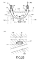
- the implant main body 91 is inserted into the main body 31 while being taken out from the packaging material 92, and as shown in FIG. 25 (a), the band 912 is projected from the proximal end opening and the distal end opening of the main body 31; To do.
- contamination of the implant main body 91 can be prevented by accommodating the implant main body 91 in the packaging material 92 until immediately before being disposed in the main body 31.
- the main body 31 has a flat shape
- the posture of the main body portion 911 follows this flat shape. That is, as shown in FIG. 25 (b), the main body portion 911 is arranged in the main body 31 so that the width direction thereof coincides with the width direction of the main body 31. From the relationship with the urethra 1300, the implant body 91 is disposed in parallel with the corrected urethra 1300.
- the thread 341 exposed from the exposure holes 345 and 346 is cut.
- the main body 31 can be divided into the tip split piece 32 and the base split piece 33. Since the exposure holes 345 and 346 are located on the proximal end side with respect to the anchor 82, the exposure holes 345 and 346 are surely exposed to the outside of the living body. Therefore, the yarn 341 can be easily cut.
- the connection between the distal end split piece 32 and the proximal end split piece 33 is released, the distal end split piece 32 is pulled out from the living body toward the distal end side, and the proximal end split piece 33 is pulled out from the living body toward the proximal end side.
- the tip split piece 32 and the base end split piece 33 are moved substantially simultaneously in opposite directions, and the tip split piece 32 and the base end split piece 33 are each moved in an arc shape along the shape thereof. Thereby, the main body 31 is smoothly removed from the living body.
- the distal-end divided piece 32 and the proximal-end divided piece 33 are removed from the living body as described above, the surrounding tissue that has been spread by the main body 31 returns to the original position, and both end portions from the central portion of the implant main body 91 are restored.
- the tissue gradually comes into contact with the implant body 91 toward the end.
- the distal end divided piece 32 and the proximal end divided piece 33 are moved in the direction along the shape thereof, and the main body 31 has an internal space in which the implant main body 91 can move with a sufficiently low sliding.
- an unnecessary tensile force is not applied to the implant body 91, and the implant body 91 can be placed as it is. Thereby, adjustment of the tension of the implant main body 91 becomes unnecessary.
- the implant body 91 is embedded in the living body.
- the body portion 911 is disposed substantially parallel to the urethra 1300 in a region between the urethra 1300 and the vagina 1400. Therefore, the urethra 1300 can be supported in a wider area by the implant body 91.
- the main body 31 can be easily removed from the living body by dividing the main body 31 and removing it from the living body. Further, since the main body 31 can be removed from the living body without removing the anchors 81 and 82 from the main body 31, the main body 31 can be easily removed. Further, according to such an extraction method, the divided pieces 32 and 33 being extracted hardly affect the posture of the main body 911 in the region between the urethra 1300 and the vagina 1400.
- the urethra insertion member 4 is removed from the urethra 1300.
- the urethra 1300 returns to the natural shape, but the main body portion 911 is embedded in the tissue, so that the urethra 1300 in the natural state and the main body portion 911 are maintained in a parallel state. Can do. Thereafter, unnecessary portions of the implant body 91 are excised, and the procedure is finished.
- the puncture device 1 when the implant 9 is placed, it can be handled only by a minimally invasive technique such as puncture of the puncture member 3, and it is not necessary to perform a highly invasive incision or the like. Therefore, the burden on the patient is small and the safety of the patient is high. Further, since the implant body 91 can be embedded in parallel with the urethra 1300, the urethra 1300 can be supported in a wider area. Further, the puncture member 3 can puncture the living body while avoiding the urethra 1300 and the vagina 1400, and the puncture member 3 can be prevented from puncturing the urethra 1300 and the vagina 1400, which is safe. Further, it is possible to prevent the occurrence of complications such as the exposure of the implant 9 into the vagina from the wound created by the incision and the infection from the wound as in the case of the conventional incision of the vagina. It is possible to embed the implant 9 reliably.
- FIG. 27 is a perspective view showing a medical tube (medical tube assembly) according to a second embodiment of the present invention.
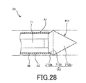
- FIG. 28 is a sectional view showing a modification of the medical tube (medical tube assembly) shown in FIG.
- This embodiment is the same as the first embodiment described above except that the configuration of the puncture member is mainly different.
- the puncture member 3A of the present embodiment is composed of a sheath 30. That is, the puncture member 3A has a configuration in which the needle body 35 is omitted from the puncture member 3 of the first embodiment described above. Further, in a state (initial state) in which the insertion portion 71 is inserted into the puncture member 3, the distal end portion 711 that is the distal end portion of the insertion portion 71 protrudes from the distal end side opening of the main body 31. The tip 711 protruding from the main body 31 also serves as the needle tip of the puncture member 3A.
- the distal end portion 711 of the insertion portion 71 also serves as the needle body of the puncture member 3A, for example, the number of members can be reduced as compared with the first embodiment described above.
- the puncture member 3 is punctured into a living body and the insertion portion 71 is removed from the puncture member 3, the distal end side opening of the main body 31 can be opened.
- the outer diameter of the insertion portion 71 and the inner diameter of the opening on the distal end side of the main body 31 are set to be substantially the same, the displacement of the insertion portion 71 with respect to the main body 31 is prevented, and the operability is improved.
- a tapered portion 319 in which the outer diameter from the distal end side opening gradually increases toward the proximal end is provided at the distal end of the main body 31.
- the tapered portion 319 functions as a peeling portion that peels off the living body gradually so as to gradually expand following the distal end portion 711 as the distal end portion 711 of the insertion portion 71 punctures the living body.
- taper angle of the taper portion 319 and the taper angle of the tip portion 711 may be the same, but are preferably different as shown in FIG. In this case, it is preferable that the taper angle of the taper portion 319 is smaller than the taper angle of the tip portion 711. Thereby, smooth puncture can be performed.
- the puncture member 3 ⁇ / b> A includes a sheath 30. That is, the puncture member 3A has a configuration in which the needle body 35 is omitted from the puncture member 3 of the first embodiment described above. Further, in a state (initial state) in which the insertion portion 71 is inserted into the puncture member 3, the distal end portion 711 that is the distal end portion of the insertion portion 71 protrudes from the distal end side opening of the main body 31.
- the tip portion 711 is provided so as to be removable from the insertion portion 71 by screwing, fitting, or the like. Further, the distal end portion 711 has a needle tip 712 protruding from the distal end of the sheath 30.
- the needle tip 712 has a flat shape following the sheath 30. Further, the needle tip 712 has an area gradually increasing portion 712a in which the cross-sectional area gradually increases toward the tip, and an area gradually decreasing portion 712b that is provided on the tip side of the area gradually increasing portion 712a and in which the cross-sectional area gradually decreases toward the tip. ing.
- the short axis of the boundary portion 712c between the area gradually increasing portion 712a and the area gradually decreasing portion 712b is longer than the short axis of the distal end of the sheath 30, and the long axis of the boundary portion 712c is longer than the long axis of the distal end of the sheath 30.
- the living body can be punctured substantially only with the needle tip 712. Therefore, puncture resistance can be reduced and puncture into a living body can be performed more smoothly.
- the short axis of the boundary portion 712c may be equal to the short axis of the distal end of the sheath 30, and the long axis of the boundary portion 712c may be equal to the long axis of the sheath 30 distal end.
- FIG. 29 is a perspective view showing a medical tube (medical tube assembly) according to a third embodiment of the present invention.
- This embodiment is the same as the first embodiment described above except that the configuration of the puncture member is mainly different.
- the main body 31B of the puncture member 3B has a configuration in which a distal end divided piece 32 and a proximal end divided piece 33 are connected via a fragile portion.
- the distal end divided piece 32, the proximal end divided piece 33, and the weakened portion 36 are integrally formed.
- the configuration of the fragile portion 36 is not particularly limited as long as it is more brittle than the front end split piece 32 and the base end split piece 33 and can be easily broken.
- it has a perforation 361 provided so as to go around the main body 31. It can be configured.
- the fragile portion 36 is broken, and the distal divided piece 32 and the proximal divided piece are separated.
- the piece 33 is separated. According to such a configuration, there is no overlap between the tip split piece 32 and the base end split piece 33 as in the first embodiment described above, and therefore there is a step at the boundary between the tip split piece 32 and the base end split piece 33. Therefore, the puncture of the puncture member 3B and the insertion of the implant main body 91 into the main body 31 can be performed smoothly.
- the fragile portion 36 also serves as a state maintaining mechanism for maintaining the connection state between the distal end divided piece 32 and the proximal end divided piece 33, the state maintaining mechanism 34 as in the first embodiment described above may be omitted. it can. Therefore, the configuration of the puncture member 3B can be simplified.
- FIG. 30 is a perspective view showing a medical tube (medical tube assembly) according to a fourth embodiment of the present invention.
- This embodiment is the same as the first embodiment described above except that the configuration of the puncture member is mainly different.
- the state maintaining mechanism 34C included in the puncture member 3C of the present embodiment is further inserted into the hole 342d, 342e and the holes 342d, 342e in the state maintaining mechanism 34 of the first embodiment described above. And an endless thread (connecting member) 349.
- the hole 342d is provided at the distal end portion of the base end split piece 33 and closer to the inner peripheral portion A1 of the surface A3.
- the hole 342e is a proximal end portion of the distal end split piece 32 and is provided from the outer peripheral portion A2 of the surface A3.
- the thread 349 is prepared, for example, as a thread with ends, and one end of the thread 349 is inserted into the main body 31 from the proximal end opening 332, pulled out of the main body 31 from the hole 342d, and inserted into the main body 31 from the hole 342e. It is obtained by pulling it out of the main body 31 from the hole 342a and finally tying it with the other end in the vicinity of the base end side opening 332.
- the position of the knot is not limited.
- the thread 349 is exposed to the outside of the main body 31 through the exposure holes 345 and 346 in the same manner as the thread 341. Therefore, similarly to the thread 341, it can be cut through the exposure holes 345 and 346.
- the thread 349 By drawing the thread 349 in this way, the following effects can be exhibited. That is, in the first embodiment described above, the holes 342a, 342b, and 342c are all formed closer to the inner peripheral portion A1, and the yarn 341 is also drawn around from the inner peripheral portion A1. Therefore, contraction force is applied to the inner peripheral portion A1 side, and the main body 31 may be deformed so that the outer peripheral portion A2 side of the split pieces 32 and 33 is separated from each other.
- a gap may be formed at the boundary between the divided pieces 32 and 33, or a large step may be formed, which may affect the puncture of the living body. Therefore, as in this embodiment, a hole 342d near the inner peripheral portion A1 of the base end split piece 33 and a hole 342e near the outer peripheral portion A2 of the tip split piece 32 are formed, and the thread 349 is drawn around them.
- the deformation as described above can be suppressed, and the main body 31 can be maintained in a predetermined shape.
- the state maintaining mechanism 34C uses the two yarns 341 and 349, but these yarns may be combined into one (yarn 341).
- one end of the thread 341 is inserted into the main body 31 from the proximal end opening 332, pulled out of the main body 31 from the hole 342d, and inserted into the main body 31 from the hole 342e. It is obtained by pulling out from the hole 342b to the outside of the main body 31, inserting into the main body 31 from the hole 342c, pulling out from the hole 342a to the outside of the main body 31, and finally connecting to the other end in the vicinity of the proximal end opening 332.
- FIG. 31 is a perspective view showing a medical tube (medical tube assembly) according to a fifth embodiment of the present invention.
- This embodiment is the same as the first embodiment described above except that the configuration of the puncture member is mainly different.
- the state maintaining mechanism 34D included in the puncture member 3D according to the present embodiment omits the hole 342c from the state maintaining mechanism 34 according to the first embodiment described above, and uses a thread 341 having an end shape. .
- the thread 341 is disposed in the main body 31.
- One end of the thread 341 protrudes from the hole 342a, and a knot 341a is formed at the protruding portion.
- the knot 341a has such a size that it cannot pass through the hole 342a.
- the other end of the thread 341 protrudes from the hole 342b, and a knot 341b is formed at the protruding portion.
- the knot 341b has such a size that it cannot pass through the hole 342b.
- the state maintaining mechanism 34D maintains the connection state of the distal end divided piece 32 and the proximal end divided piece 33 by arranging the thread 341 in this way.
- FIG. 32 is a cross-sectional view showing a medical tube (medical tube assembly) according to a sixth embodiment of the present invention.
- This embodiment is the same as the first embodiment described above except that the configuration of the puncture member is mainly different.
- the state maintaining mechanism 34E of the puncture member 3E of the present embodiment is inserted into the holes 342f, 342g, 342h, 342i and the respective wires 342f, 342g, 342h, 342i, and has an elastic wire (line ) 39.
- the holes 342f and 342g are provided in the axial direction at the distal end portion of the inner peripheral portion A1 of the proximal end split piece 33, and the holes 342h and 342i are axially provided at the proximal end portion of the inner peripheral portion A1 of the distal end split piece 32. It is provided side by side. Further, the holes 342f and 342h are overlapped, and the holes 342g and 342i are overlapped.
- the wire 39 is drawn out of the main body 31 through the holes 342f and 342h and introduced into the main body 31 through the holes 342g and 342i. Thereby, the connection state of the division
- the wire 39 is not particularly limited, and for example, a wire made of various metal materials such as stainless steel, a cobalt alloy, a nickel alloy, or a wire made of a piano wire can be used.
- FIG. 33 is a view showing a medical tube (medical tube assembly) according to a seventh embodiment of the present invention, in which (a) is a plan view, and (b) and (c) are sectional views.
- the puncture member extending in an arc shape is linearly extended and illustrated.
- This embodiment is the same as the first embodiment described above except that the configuration of the puncture member is mainly different.
- the state maintaining mechanism 34F included in the puncture member 3F of the present embodiment includes a hole 342a, a hole 352a provided in the proximal end portion 352 of the needle body 35, and a thread 341.
- the thread 341 is disposed in the main body 31, is engaged with the needle body 35 by being inserted through the hole 352a, and is engaged with the proximal end split piece 33 by being inserted through the hole 342a.
- the divided pieces 32 and 33 can be divided by cutting the yarn 341.
- the thread 341 is prepared, for example, as a thread with ends, and one end of the thread 341 is inserted into the main body 31 through the base end side opening 332, pulled out of the main body 31 from the hole 342a through the hole 352a, and finally. It is obtained by tying the other end in the vicinity of the base end side opening 332.
- FIG. 34 is a cross-sectional view showing a medical tube (medical tube assembly) according to an eighth embodiment of the present invention.
- FIG. 35 is a cross-sectional view showing a modification of the medical tube shown in FIG.
- This embodiment is the same as the first embodiment described above except that the configuration of the puncture member is mainly different.
- the state maintaining mechanism 34G included in the puncture member 3G of the present embodiment includes holes 342j and 342k provided in the distal end divided piece 32, and protrusions 343a and 343b provided in the proximal end divided piece 33. , And a stylet (tube body) 344 inserted into the main body 31.
- the holes 342j and 342k are formed to be divided into a front surface A3 and a back surface A4 of the base end portion of the tip split piece 32.
- the protrusions 343a and 343b are formed separately on the front surface A3 and the back surface A4 of the distal end portion of the base end split piece 33.
- the protrusion 343a is engaged with the hole 342j, and the protrusion 343b is engaged with the hole 342k.
- the stylet 344 is inserted into the main body 31, and the stylet 344 regulates the inward displacement of the protrusions 343a and 343b. Even with such a configuration, the connection state of the split pieces 32 and 33 can be maintained. In the state maintaining mechanism 34G, the divided pieces 32 and 33 can be divided by pulling out the stylet 344 from the main body 31 so that the protrusions 343a and 343b can be displaced inward.
- a hard material that can regulate the displacement of the protrusions 343a and 343b.
- a hard material include various resin materials such as polyethylene, polyimide, polyamide, polyester elastomer, and polypropylene, and various metal materials such as stainless steel, aluminum or aluminum alloy, titanium or titanium alloy, and the like.
- the wall can be reinforced with a reinforcing member.
- the state maintaining mechanism 34G has the stylet 344.
- the insertion portion 71 inserted into the main body 31 may also serve as the stylet 344. That is, the insertion portion 71 may be configured to restrict the inward displacement of the protrusions 343a and 343b.
- FIG. 36 is a view showing a medical tube (medical tube assembly) according to a ninth embodiment of the present invention, in which (a) is a plan view, and (b) and (c) are sectional views.
- the puncture member extending in an arc shape is linearly extended and illustrated.
- This embodiment is the same as the first embodiment described above except that the configuration of the puncture member is mainly different.
- the state maintaining mechanism 34H included in the puncture member 3H of the present embodiment includes a hole 342l provided in the tip split piece 32 and a wire 38 having elasticity.
- the wire 38 has a distal end hook (claw portion) 381 hooked in the hole 342l at the distal end portion, and a proximal end hook (claw) hooked on the proximal end of the proximal end split piece 33 at the proximal end portion. Part) 382. Then, by hooking the tip hook 381 and the base end hook 382 to the hole 342l and the base end split piece 33, the connection state of the split pieces 32 and 33 can be maintained.
- the divided pieces 32 and 33 are divided by pushing the wire 38 toward the distal end, retracting the distal hook 381 into the main body 31, and releasing the engagement between the distal hook 381 and the hole 342l. It will be in a state that can be.
- the needle body is detachably held on the main body.
- the present invention is not limited thereto, and the needle body is fixed to the main body, for example, the main body and the needle body are integrally formed. May be.
- the distal end side opening of the main body can be opened by puncturing the living body with the puncture member and projecting the needle body out of the living body, and then cutting the needle body with a scissors or the like.
- the sheath is configured as a part of the puncture member, but is not limited thereto. That is, a sheath may be inserted into a through-hole formed in a living body using some means first.
- the method for forming the through hole in the living body is not particularly limited.
- a device in which the puncture member is omitted from the puncture device described above can be used.
- the insertion portion functions as a puncture member.
- the puncture device is applied to a device used when an implantable implant for treating urinary incontinence in women is embedded in a living body.
- the use of the puncture device is limited thereto. Is not to be done.
- the present invention relates to excretion disorder (urinary urgency, frequent urination, urinary incontinence, stool incontinence, urinary retention, difficulty in urination, etc.), pelvic organ prolapse, cystovaginal fistula, urethral vagina Pelvic floor diseases including epilepsy, pelvic pain, etc. are included in the target of application.
- Pelvic organ prolapse includes diseases such as cystocele, small intestinal aneurysm, rectal aneurysm, and uterine prolapse.
- diseases such as anterior vaginal wall prolapse, posterior vaginal wall prolapse, vaginal stump prolapse, and vaginal vault prolapse are classified according to the vagina wall site being removed.
- the hypermovable tissue includes bladder, vagina, uterus, intestine and the like.
- Micro-movable tissues include bones, muscles, fascia, ligaments and the like.
- pelvic floor disease it includes obturator fascia, coccyx fascia, proximal ligament, sacral uterine ligament, sacrospinous ligament, and the like.
- procedures to connect hypermovable tissue to micromovable tissue include retropubic sling surgery, transobturator sling surgery (transobturator sling surgery, transobturator tape; TOT), transvaginal mesh surgery (Tension-free Vaginal Mesh; TVM), elevation using sacral uterine ligament (Uterosacral Ligament Suspension; USLS), fusion using sacrospinous ligament (Sacrospinous Ligament Fixation; SSLF), fusion using iliac coccyx fascia, tailbone Includes fusion using the fascia.
- the medical tube of the present invention is a medical tube used when introducing a long strip for treating pelvic organs into a living body, and the tube is formed at the proximal end of the distal split piece that forms the tube.
- the main body can be arranged in the body while maintaining the connection state between the distal end divided piece and the proximal end divided piece, and the main body can be smoothly arranged in the body.
- the main body when removing the main body from the body, by releasing the state maintaining mechanism, it is possible to remove the distal end divided piece from the distal end side and the proximal end divided piece from the proximal end side.
- the main body can be easily removed from the body by dividing the main body into two pieces and removing it.
- the main body can be removed from the body while maintaining the posture of the implant disposed inside the main body.
- the medical tube of the present invention has industrial applicability.
Abstract
Priority Applications (4)
| Application Number | Priority Date | Filing Date | Title |
|---|---|---|---|
| PCT/JP2013/059897 WO2014162432A1 (fr) | 2013-04-01 | 2013-04-01 | Tube médical et ensemble tube médical |
| EP13881310.0A EP2982311A4 (fr) | 2013-04-01 | 2013-04-01 | Tube médical et ensemble tube médical |
| JP2015509686A JP6092368B2 (ja) | 2013-04-01 | 2013-04-01 | 医療用チューブおよび医療用チューブ組立体 |
| US14/873,126 US10143468B2 (en) | 2013-04-01 | 2015-10-01 | Medical tube and medical tube assembly |
Applications Claiming Priority (1)
| Application Number | Priority Date | Filing Date | Title |
|---|---|---|---|
| PCT/JP2013/059897 WO2014162432A1 (fr) | 2013-04-01 | 2013-04-01 | Tube médical et ensemble tube médical |
Related Child Applications (1)
| Application Number | Title | Priority Date | Filing Date |
|---|---|---|---|
| US14/873,126 Continuation US10143468B2 (en) | 2013-04-01 | 2015-10-01 | Medical tube and medical tube assembly |
Publications (1)
| Publication Number | Publication Date |
|---|---|
| WO2014162432A1 true WO2014162432A1 (fr) | 2014-10-09 |
Family
ID=51657766
Family Applications (1)
| Application Number | Title | Priority Date | Filing Date |
|---|---|---|---|
| PCT/JP2013/059897 WO2014162432A1 (fr) | 2013-04-01 | 2013-04-01 | Tube médical et ensemble tube médical |
Country Status (4)
| Country | Link |
|---|---|
| US (1) | US10143468B2 (fr) |
| EP (1) | EP2982311A4 (fr) |
| JP (1) | JP6092368B2 (fr) |
| WO (1) | WO2014162432A1 (fr) |
Families Citing this family (5)
| Publication number | Priority date | Publication date | Assignee | Title |
|---|---|---|---|---|
| US10195014B2 (en) | 2005-05-20 | 2019-02-05 | Neotract, Inc. | Devices, systems and methods for treating benign prostatic hyperplasia and other conditions |
| CN107206620B (zh) * | 2014-11-06 | 2019-12-31 | 地板技术有限公司 | 尤其呈木塑复合材料形式的木质材料板和用于其制造的方法 |
| CN110478010B (zh) * | 2019-09-23 | 2020-12-15 | 常州安康医疗器械有限公司 | 一种腹腔镜穿刺器械保护装置 |
| CN114286646B (zh) | 2020-08-03 | 2024-03-08 | 泰利福生命科学有限公司 | 用于医疗干预的手柄和匣盒系统 |
| CN113425222B (zh) * | 2021-05-18 | 2022-10-04 | 陕西吾方医疗科技有限公司 | 一种具有单向膨胀气囊的宫腔镜 |
Citations (12)
| Publication number | Priority date | Publication date | Assignee | Title |
|---|---|---|---|---|
| JPH11514266A (ja) * | 1995-10-09 | 1999-12-07 | メドスカンド メディカル アクティエボラーグ | 女性尿失禁を治療するための外科用器具 |
| US6168611B1 (en) * | 1999-09-08 | 2001-01-02 | Syed Rizvi | Suturing needle assemblies and methods of use thereof |
| JP2003512123A (ja) * | 1999-10-22 | 2003-04-02 | ジョージ・カラデルフォス | 外科手術用器具 |
| US20030171644A1 (en) | 2002-03-07 | 2003-09-11 | Anderson Kimberly A. | Transobturator surgical articles and methods |
| JP2004510489A (ja) * | 2000-10-05 | 2004-04-08 | ソフラディム・プロダクション | 女性の腹圧性尿失禁の処置に際しての尿道下支持アセンブリ |
| JP2004526483A (ja) * | 2001-01-23 | 2004-09-02 | アメリカン メディカル システムズ インコーポレイテッド | スリング送達システム |
| US20040249240A1 (en) * | 2001-08-03 | 2004-12-09 | Helmut Goldmann | Incontinence strip for treating urinary incontinence |
| JP2005505313A (ja) * | 2001-03-09 | 2005-02-24 | サイムド ライフ システムズ, インコーポレイテッド | インプラントを移植するためのシステムおよびその方法 |
| WO2006005117A1 (fr) * | 2004-07-09 | 2006-01-19 | George Kaladelfos | Dispositif d'introduction et de deploiement pour bande chirurgicale |
| JP2008508046A (ja) * | 2004-07-28 | 2008-03-21 | エシコン・インコーポレイテッド | 低侵襲性医療インプラントならびにその挿入器具および使用方法 |
| WO2011125947A1 (fr) * | 2010-04-01 | 2011-10-13 | 国立大学法人宮崎大学 | Aiguille d'insertion |
| US20120197281A1 (en) * | 2011-01-31 | 2012-08-02 | Boston Scientific Scimed, Inc. | Deflection member for delivering implants and methods of delivering implants |
Family Cites Families (6)
| Publication number | Priority date | Publication date | Assignee | Title |
|---|---|---|---|---|
| GB2359256B (en) * | 2000-01-21 | 2004-03-03 | Sofradim Production | Percutaneous device for treating urinary stress incontinence in women using a sub-urethral tape |
| US6991597B2 (en) | 2001-03-09 | 2006-01-31 | Boston Scientific Scimed, Inc. | System for implanting an implant and method thereof |
| US7303525B2 (en) * | 2003-08-22 | 2007-12-04 | Ams Research Corporation | Surgical article and methods for treating female urinary incontinence |
| WO2006108045A2 (fr) * | 2005-04-05 | 2006-10-12 | Ans Research Corporation | Articles, dispositifs et procedes de chirurgie pelvienne |
| US8430807B2 (en) * | 2007-12-28 | 2013-04-30 | Boston Scientific Scimed, Inc. | Devices and methods for treating pelvic floor dysfunctions |
| WO2014033812A1 (fr) * | 2012-08-27 | 2014-03-06 | テルモ株式会社 | Tube médical, ensemble tube médical et aiguille de ponction |
-
2013
- 2013-04-01 WO PCT/JP2013/059897 patent/WO2014162432A1/fr active Application Filing
- 2013-04-01 EP EP13881310.0A patent/EP2982311A4/fr not_active Withdrawn
- 2013-04-01 JP JP2015509686A patent/JP6092368B2/ja active Active
-
2015
- 2015-10-01 US US14/873,126 patent/US10143468B2/en active Active
Patent Citations (12)
| Publication number | Priority date | Publication date | Assignee | Title |
|---|---|---|---|---|
| JPH11514266A (ja) * | 1995-10-09 | 1999-12-07 | メドスカンド メディカル アクティエボラーグ | 女性尿失禁を治療するための外科用器具 |
| US6168611B1 (en) * | 1999-09-08 | 2001-01-02 | Syed Rizvi | Suturing needle assemblies and methods of use thereof |
| JP2003512123A (ja) * | 1999-10-22 | 2003-04-02 | ジョージ・カラデルフォス | 外科手術用器具 |
| JP2004510489A (ja) * | 2000-10-05 | 2004-04-08 | ソフラディム・プロダクション | 女性の腹圧性尿失禁の処置に際しての尿道下支持アセンブリ |
| JP2004526483A (ja) * | 2001-01-23 | 2004-09-02 | アメリカン メディカル システムズ インコーポレイテッド | スリング送達システム |
| JP2005505313A (ja) * | 2001-03-09 | 2005-02-24 | サイムド ライフ システムズ, インコーポレイテッド | インプラントを移植するためのシステムおよびその方法 |
| US20040249240A1 (en) * | 2001-08-03 | 2004-12-09 | Helmut Goldmann | Incontinence strip for treating urinary incontinence |
| US20030171644A1 (en) | 2002-03-07 | 2003-09-11 | Anderson Kimberly A. | Transobturator surgical articles and methods |
| WO2006005117A1 (fr) * | 2004-07-09 | 2006-01-19 | George Kaladelfos | Dispositif d'introduction et de deploiement pour bande chirurgicale |
| JP2008508046A (ja) * | 2004-07-28 | 2008-03-21 | エシコン・インコーポレイテッド | 低侵襲性医療インプラントならびにその挿入器具および使用方法 |
| WO2011125947A1 (fr) * | 2010-04-01 | 2011-10-13 | 国立大学法人宮崎大学 | Aiguille d'insertion |
| US20120197281A1 (en) * | 2011-01-31 | 2012-08-02 | Boston Scientific Scimed, Inc. | Deflection member for delivering implants and methods of delivering implants |
Non-Patent Citations (1)
| Title |
|---|
| See also references of EP2982311A4 * |
Also Published As
| Publication number | Publication date |
|---|---|
| US20160022265A1 (en) | 2016-01-28 |
| US10143468B2 (en) | 2018-12-04 |
| EP2982311A1 (fr) | 2016-02-10 |
| EP2982311A4 (fr) | 2016-09-21 |
| JPWO2014162432A1 (ja) | 2017-02-16 |
| JP6092368B2 (ja) | 2017-03-08 |
Similar Documents
| Publication | Publication Date | Title |
|---|---|---|
| JP6092367B2 (ja) | 穿刺装置 | |
| WO2014162434A1 (fr) | Dispositif de ponction | |
| JP6092368B2 (ja) | 医療用チューブおよび医療用チューブ組立体 | |
| JP2015058121A (ja) | インプラントおよびインプラントの留置方法 | |
| JP5989232B2 (ja) | 医療用チューブ、医療用チューブ組立体および骨盤内治療用キット | |
| WO2015041080A1 (fr) | Outil d'insertion dans un corps vivant et procédé d'aspiration | |
| WO2015041172A1 (fr) | Dispositif de ponction et procédé de ponction | |
| JP2015061553A (ja) | 医療用チューブ | |
| JP2015058074A (ja) | 穿刺装置および穿刺方法 | |
| WO2015137116A1 (fr) | Élément de ponction | |
| JP2015061560A (ja) | 穿刺装置および穿刺方法 | |
| JP2015061568A (ja) | 生体挿入装置 | |
| WO2015041170A1 (fr) | Outil d'introduction et procédé pour introduire l'outil d'introduction | |
| WO2015041140A1 (fr) | Dispositif de ponction et procédé de ponction | |
| WO2015041145A1 (fr) | Ensemble tube médical et dispositif de perforation | |
| JP2015173755A (ja) | 穿刺部材 | |
| JP2015058073A (ja) | 穿刺装置および穿刺方法 | |
| WO2015137115A1 (fr) | Élément de ponction | |
| JP2015058323A (ja) | インプラントの留置方法 | |
| JP2015058318A (ja) | 膣挿入具および穿刺方法 | |
| JP2015058312A (ja) | 穿刺装置および穿刺方法 | |
| JP2015058316A (ja) | 尿道挿入具 | |
| JP2015061552A (ja) | 医療用チューブ、医療用チューブ組立体および穿刺方法 | |
| JP2015061554A (ja) | 医療用チューブ | |
| WO2015041078A1 (fr) | Tube médical, ensemble d'outil médical et procédé d'implantation d'implant |
Legal Events
| Date | Code | Title | Description |
|---|---|---|---|
| 121 | Ep: the epo has been informed by wipo that ep was designated in this application |
Ref document number: 13881310 Country of ref document: EP Kind code of ref document: A1 |
|
| ENP | Entry into the national phase |
Ref document number: 2015509686 Country of ref document: JP Kind code of ref document: A |
|
| REEP | Request for entry into the european phase |
Ref document number: 2013881310 Country of ref document: EP |
|
| WWE | Wipo information: entry into national phase |
Ref document number: 2013881310 Country of ref document: EP |
|
| NENP | Non-entry into the national phase |
Ref country code: DE |