WO2014162364A1 - 膣内部支持具及び流体注入デバイス - Google Patents
膣内部支持具及び流体注入デバイス Download PDFInfo
- Publication number
- WO2014162364A1 WO2014162364A1 PCT/JP2013/002379 JP2013002379W WO2014162364A1 WO 2014162364 A1 WO2014162364 A1 WO 2014162364A1 JP 2013002379 W JP2013002379 W JP 2013002379W WO 2014162364 A1 WO2014162364 A1 WO 2014162364A1
- Authority
- WO
- WIPO (PCT)
- Prior art keywords
- vaginal
- vagina
- internal support
- insertion guide
- bag
- Prior art date
- Legal status (The legal status is an assumption and is not a legal conclusion. Google has not performed a legal analysis and makes no representation as to the accuracy of the status listed.)
- Ceased
Links
Images








Classifications
-
- A—HUMAN NECESSITIES
- A61—MEDICAL OR VETERINARY SCIENCE; HYGIENE
- A61F—FILTERS IMPLANTABLE INTO BLOOD VESSELS; PROSTHESES; DEVICES PROVIDING PATENCY TO, OR PREVENTING COLLAPSING OF, TUBULAR STRUCTURES OF THE BODY, e.g. STENTS; ORTHOPAEDIC, NURSING OR CONTRACEPTIVE DEVICES; FOMENTATION; TREATMENT OR PROTECTION OF EYES OR EARS; BANDAGES, DRESSINGS OR ABSORBENT PADS; FIRST-AID KITS
- A61F6/00—Contraceptive devices; Pessaries; Applicators therefor
- A61F6/06—Contraceptive devices; Pessaries; Applicators therefor for use by females
- A61F6/08—Pessaries, i.e. devices worn in the vagina to support the uterus, remedy a malposition or prevent conception, e.g. combined with devices protecting against contagion
- A61F6/12—Inserters or removers
-
- A—HUMAN NECESSITIES
- A61—MEDICAL OR VETERINARY SCIENCE; HYGIENE
- A61F—FILTERS IMPLANTABLE INTO BLOOD VESSELS; PROSTHESES; DEVICES PROVIDING PATENCY TO, OR PREVENTING COLLAPSING OF, TUBULAR STRUCTURES OF THE BODY, e.g. STENTS; ORTHOPAEDIC, NURSING OR CONTRACEPTIVE DEVICES; FOMENTATION; TREATMENT OR PROTECTION OF EYES OR EARS; BANDAGES, DRESSINGS OR ABSORBENT PADS; FIRST-AID KITS
- A61F2/00—Filters implantable into blood vessels; Prostheses, i.e. artificial substitutes or replacements for parts of the body; Appliances for connecting them with the body; Devices providing patency to, or preventing collapsing of, tubular structures of the body, e.g. stents
- A61F2/0004—Closure means for urethra or rectum, i.e. anti-incontinence devices or support slings against pelvic prolapse
- A61F2/0031—Closure means for urethra or rectum, i.e. anti-incontinence devices or support slings against pelvic prolapse for constricting the lumen; Support slings for the urethra
- A61F2/005—Closure means for urethra or rectum, i.e. anti-incontinence devices or support slings against pelvic prolapse for constricting the lumen; Support slings for the urethra with pressure applied to urethra by an element placed in the vagina
-
- A—HUMAN NECESSITIES
- A61—MEDICAL OR VETERINARY SCIENCE; HYGIENE
- A61F—FILTERS IMPLANTABLE INTO BLOOD VESSELS; PROSTHESES; DEVICES PROVIDING PATENCY TO, OR PREVENTING COLLAPSING OF, TUBULAR STRUCTURES OF THE BODY, e.g. STENTS; ORTHOPAEDIC, NURSING OR CONTRACEPTIVE DEVICES; FOMENTATION; TREATMENT OR PROTECTION OF EYES OR EARS; BANDAGES, DRESSINGS OR ABSORBENT PADS; FIRST-AID KITS
- A61F6/00—Contraceptive devices; Pessaries; Applicators therefor
- A61F6/06—Contraceptive devices; Pessaries; Applicators therefor for use by females
- A61F6/08—Pessaries, i.e. devices worn in the vagina to support the uterus, remedy a malposition or prevent conception, e.g. combined with devices protecting against contagion
-
- A—HUMAN NECESSITIES
- A61—MEDICAL OR VETERINARY SCIENCE; HYGIENE
- A61F—FILTERS IMPLANTABLE INTO BLOOD VESSELS; PROSTHESES; DEVICES PROVIDING PATENCY TO, OR PREVENTING COLLAPSING OF, TUBULAR STRUCTURES OF THE BODY, e.g. STENTS; ORTHOPAEDIC, NURSING OR CONTRACEPTIVE DEVICES; FOMENTATION; TREATMENT OR PROTECTION OF EYES OR EARS; BANDAGES, DRESSINGS OR ABSORBENT PADS; FIRST-AID KITS
- A61F2210/00—Particular material properties of prostheses classified in groups A61F2/00 - A61F2/26 or A61F2/82 or A61F9/00 or A61F11/00 or subgroups thereof
- A61F2210/0061—Particular material properties of prostheses classified in groups A61F2/00 - A61F2/26 or A61F2/82 or A61F9/00 or A61F11/00 or subgroups thereof swellable
Definitions
- the present invention relates to a vaginal internal support device that can be used for the treatment of pelvic organ prolapse and that can be expanded and contracted while inserted into the vagina, and in particular, facilitates insertion into the vagina and holds it in the vagina of a patient. I will try to let you.
- the present invention also relates to a fluid injection device for inflating the vaginal internal support, and particularly to facilitate fluid injection operation.
- Pelvic organ prolapse is a disease in which organs such as the uterus, bladder, and rectum in the pelvis hang down, and in severe cases, escape from the body. Strong discomfort, dysuria, difficulty in defecation, Causes symptoms such as pain.
- vaginal births develop with aging and the number of potential patients in the country is 3.5 million.
- a pessary usually consists of an elastically deformable ring body, which is inserted and placed in the patient's vagina by a doctor to support the drooping of the cervix, the anterior wall of the vagina, the posterior wall of the vagina, etc. Suppress.
- the surrounding soft vagina wall can be pushed and deformed, whereas in areas where the pubic tissue is deep, the depth leading to the pubic tissue The above indentation deformation is difficult.
- the pessary is pressed against the region slightly behind the vagina than the region where the pubic tissue exists in the deep part of the vagina (that is, the region near the cervix side of the pubic tissue on the anterior vagina)
- a recess is formed by the deformable region and the region in which push-in deformation is difficult, and the pessary is locked in the recess.
- pessaries may cause off-flavors if left in the body for a long period of time or cause bleeding from the compressed area, so periodically remove them from the body, reinsert them, and place them again. Or it is necessary to insert and arrange a new article.
- the pessary has a ring body whose outer diameter is considerably larger than that of the vaginal entrance, and is not easy to remove. For this reason, as an alternative to the pessary, a vaginal internal support that can expand and contract in the vagina has been proposed.
- the vaginal internal support device described in Patent Document 1 is not necessarily easy to insert into the vagina because the entire internal vaginal support device is large and rigid. For this reason, it may take time and labor to insert and reinstall the vaginal internal support.
- an inflating portion is provided around the vagina internal support device, but the entire inflating portion is inflated or contracted uniformly by introducing air. Therefore, it cannot be said that the shape change according to the internal shape of the vagina is necessarily achieved. For this reason, there are cases in which the retention in the vagina is insufficient, the effect of suppressing the pelvic organ prolapse is not sufficiently obtained, and a disorder such as bleeding or erosion occurs due to a compression site.
- the vaginal internal support of the present invention preferably promotes the expansion direction of the bag portion toward the vaginal front wall.
- the insertion guide portion has a cover portion that covers an end portion of the bag portion on the back side of the vagina.
- the insertion guide portion is formed by two members that can rotate with respect to each other via a shaft.
- the insertion guide portion has a locking piece for locking to the pubic tissue at the end of the insertion guide portion on the vaginal entrance side through the anterior vaginal wall. Is preferred.
- the insertion guide portion has an opening for expanding the bag portion and fitting the expanded bag portion to the vagina rear wall.
- the ring-shaped pressing portion is connected to an end portion on the vaginal entrance side of the insertion guide portion.
- the fluid injection device for inflating the vaginal internal support device of the present invention is connected to the vaginal internal support device and has an injection port having an injection port communicating with the opening and closing unit, and is sent to the injection port of the injection unit
- the insertion guide portion can be inserted into the vagina together with the bag portion while sliding the bag against the vagina wall in a state in which the bag portion is appropriately contracted.
- the vaginal internal support can be held in the vagina. Therefore, according to the present invention, it is possible to obtain a vaginal internal support that can be easily inserted into the vagina and can be held in the patient's vagina.
- the insertion guide portion promotes the expansion direction of the bag portion toward the vaginal front wall, the intravaginal device is inserted into the vagina, and the bag portion is fluidized. Is allowed to flow through the opening / closing part and the bag part is inflated toward the anterior wall of the vagina, so that part of the bag part can be locked to the pubic tissue via the anterior vagina wall. It can be securely held in the patient's vagina.
- FIG. 1 is a perspective view of a fluid injection device according to an embodiment of the present invention.
- FIG. 4 is a longitudinal sectional view showing a state where the fluid injection device of FIG. 3 is connected to the vaginal internal support of FIG. 1 and air is injected. It is a partial longitudinal cross-sectional view which shows the state which has arrange
- FIG. 1 is a perspective view of a vaginal internal support of this example, where (a) shows an expanded state and (b) shows a contracted state.
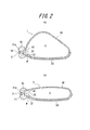
- FIG. 2 is a longitudinal sectional view of the internal vagina support of this example, where (a) shows an expanded state and (b) shows a contracted state.
- the bag part 40 has a mouth part 41 at the end of the bag part 40 on the vaginal entrance side, and forms an air storage space S that continues to the mouth part 41.
- the mouth portion 41 is integrated with the ring body 30 by, for example, bonding.
- the bag part 40 is made of an airtight elastic material, can be expanded by the inflow of air through the opening / closing part 20, and can be contracted by the outflow of air through the opening / closing part 20.
- the insertion guide portion 50 has an elliptical plate shape extending along a part of the outer surface of the bag portion 40 from the end portion on the vaginal inlet side of the bag portion 40 to the end portion on the back side of the vagina.
- the end of the insertion guide portion 50 on the vaginal entrance side is integrated with the side surface of the ring body 30 on the bag portion 40 side.
- a recess W is formed at the end of the insertion guide portion 50 on the vagina inlet side for hooking a finger when the vagina internal support 1 is taken out from the vagina.
- the insertion guide portion 50 can insert the insertion guide portion 50 into the vagina by pressing the ring body 30 integrated with the end of the insertion guide portion 50 on the vaginal entrance side toward the back of the vagina.
- it is formed of an elastic body having elasticity that does not cause pain during insertion.
- the insertion guide part 50 is elastic with elasticity that can press the bag part 40 by the insertion guide part 50 when the bag part 40 is inflated to promote the expansion of the bag part 40 toward the vaginal front wall.
- the body is preferably formed.
- As a preferable material of the insertion guide part 50 an elastomer, a soft or hard synthetic resin, etc. are mentioned, for example.
- FIG. 3 is a perspective view of the fluid injection device of this example.
- FIG. 4 is a longitudinal sectional view showing a state where the fluid injection device of this example is connected to the vaginal internal support of FIG. 1 and air is injected.
- the injection port 61 engages with the concave portion 31 of the vaginal internal support 1 by bringing the distal end surface 60a of the injection portion 60 into contact with the side surface opposite to the bag portion 40 of the ring body 30 of the vaginal internal support 1. Can be stopped. Further, the injection port 61 is drawn from the distal end surface 60a of the injection portion 60 by pressing the button B shown in FIG. 3, and the engagement with the concave portion 31 of the vagina internal support 1 is released. Yes.
- the proximal end region of the projecting portion P is bent in a substantially L shape toward the adjustment operation portion 70, and this bent portion is connected to the inside of the vagina of the vagina internal support 1. It can be used as a gripping portion H that is held by a palm when inserted into the hand.
- the adjustment operation unit 70 can adjust the amount of fluid sent to the injection port 61 of the injection unit 60 by operating the knob 71.
- the injection operation unit 80 can push the amount of fluid adjusted by the adjustment operation unit 70 to the injection port 61 of the injection unit 60 by pushing the injection operation unit 80.
- the injection operation unit 80 of the fluid injection device 2 is pushed in with the vaginal internal support 1 inserted into the vagina, the amount of air adjusted by the adjustment operation unit 70 is pumped to the injection port 61 of the injection unit 60.
- the check valve 22 of the opening / closing part 20 can be opened to allow air to flow into the bag part 40 and to inflate the bag part 40.
- the vaginal internal support 1 suppresses the expansion of the bag portion 40 toward the vagina rear wall by the insertion guide portion 50 arranged on the vagina rear wall side, while moving the bag portion 40 toward the vagina front wall. Can be promoted (the expansion direction of the bag 40 can be controlled asymmetrically with respect to the direction perpendicular to the direction from the vaginal entrance side to the vaginal back side).
- the expansion direction of the bag part 40 when air is caused to flow uniformly into the bag part 40 by the fluid injection device 2 can be controlled so that the vaginal front wall side is expanded more than the vaginal rear wall side. .
- a part of the bag part 40 is moved to the uterus of the pubic tissue C on the vaginal wall. It is possible to push into a region near the cervical N side (that is, a region closer to the pubic tissue C than the cervical N among the regions between the pubic tissue C and the cervical N).
- the guide part 50 contacts the vaginal posterior wall in a wide range, the pressure on the rectum when the bag part 40 is inflated is relieved, and the defecation disorder caused by the use of the vaginal internal support 1 is reduced or avoided. Can do.
- a part of the bag 40 can be locked to the pubic tissue C via the anterior vaginal wall.
- a force is generated in the vagina internal support 1 in the direction from the back of the vagina to the entrance of the vagina. Even in this case, it is possible to generate a drag in the direction from the vaginal entrance side to the vaginal back side.
- the vaginal internal support 1 does not necessarily need to be inserted into the vagina using the fluid injection device 2 described above, and can be inserted by pushing the ring body 30 toward the back of the vagina with a finger. .
- the injection part 60 of the fluid injection device 2 described above is inserted into the vagina, and the injection port 61 is communicated with the opening / closing part 20 to provide the inside of the vagina.
- the bag part 40 of the support tool 1 can be inflated. Therefore, in this case, the fluid injection device 2 is not limited to the one having the protrusion P as described above.
- the injection port 61 and the adjustment operation unit 70 are connected by a flexible tube. It is also possible to adopt a configuration.
- the insertion guide portion 50 can be deformed in accordance with the change in the angle of the insertion direction in the vagina from the vagina entrance to the back of the vagina, the uncomfortable feeling at the time of insertion of the vagina internal support 1 can be reduced. it can.
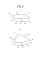
- the insertion guide portion 50 is formed by two members 53 ′ and 54 ′ that are rotatable with respect to each other via a shaft 52 ′ in the direction from the vaginal entrance side to the vaginal back side. Therefore, when inserting the vaginal internal support 1 into the vagina, the two members 53 ′ and 54 ′ are moved from the state shown in FIG. 9A to the shaft 52 ′ as shown by the arrows in FIG. 9B. Since the outer diameter of the entire vaginal internal support 1 can be reduced, the vaginal internal support 1 can be more easily inserted into the vagina. .
- a recess 55 that can be fitted to the cervix may be formed at the end of the insertion guide 50 on the back side of the vagina.
- the entire vagina internal support device 1 is inserted into the vagina while pushing the cervix hanging down at the recess 55. Can be inserted.
- the end of the insertion guide portion 50 on the vaginal entrance side is locked to the pubic tissue C shown in FIGS. 5 (a) and 5 (b) through the anterior vagina wall.
- the locking piece 56 can also be formed.
- the bag portion 40 when the bag portion 40 is inflated, the region near the cervix N side of the pubic tissue C in the anterior vaginal wall is pushed in the region of the anterior vaginal wall of the bag portion 40 so that the locking piece 56 and the anterior vaginal wall are Via the pubic tissue C.
- the bag part 40 is bulged in the insertion guide part 50, and an opening 57 for fitting the bulged bag part 40 to the vagina rear wall is formed. Can be suppressed and the therapeutic effect of rectal prolapse can be enhanced. Moreover, the opening 57 formed in the insertion guide part 50 can also be used as a hook part for hooking a finger when the vagina internal support 1 is taken out from the vagina.
- the shape of the bag part 40 when it is inflated can be reduced. Adjusting to fit the shape of the vagina, or forming a fitting recess V that can be fitted through the anterior vagina wall in the pubic tissue C shown in FIGS. 5 (a) and 5 (b). it can.
- the insertion guide portion 50 has a shape that meanders along the outer surface of the bag portion 40 from the vaginal entrance side end portion of the bag portion 40 to the vaginal depth side end portion.
- the end part on the vaginal entrance side can be integrated with the ring body 30, and the bag holding part 59 for holding the vaginal back side end part of the bag part can be provided at the end part on the back side of the vagina of the insertion guide part 50.
- the force to be pushed in can be adjusted, and the uncomfortable feeling at the time of insertion can be reduced.
- the material cost of the insertion guide part 50 can also be reduced.
- the ring body 30 has been described as being connected to the end of the insertion guide portion 50 on the vagina inlet side.
- the ring body 30 is not necessarily limited to such a configuration.
- the ring body 30 is connected to the mouth portion of the bag portion 40.
- the insertion guide part 50 can be joined to the outer surface of the bag part 40 by an adhesive or the like. In that case, when inserting the intravaginal support 1 into the vagina, the insertion guide portion 50 is pressed by the end of the insertion guide portion 50 on the vaginal entrance side toward the back of the vagina with a finger.
- the bag portion 40 can be guided into the vagina, and as a result, the vagina internal support 1 can be inserted into the vagina.
Landscapes
- Health & Medical Sciences (AREA)
- General Health & Medical Sciences (AREA)
- Veterinary Medicine (AREA)
- Biomedical Technology (AREA)
- Heart & Thoracic Surgery (AREA)
- Vascular Medicine (AREA)
- Life Sciences & Earth Sciences (AREA)
- Engineering & Computer Science (AREA)
- Animal Behavior & Ethology (AREA)
- Public Health (AREA)
- Urology & Nephrology (AREA)
- Reproductive Health (AREA)
- Cardiology (AREA)
- Oral & Maxillofacial Surgery (AREA)
- Transplantation (AREA)
- Orthopedics, Nursing, And Contraception (AREA)
- Surgical Instruments (AREA)
Abstract
本発明の膣内部支持具(1)は、流体を通過させる開放状態と流体の通過を遮断する遮断状態との間で切り換え動作可能な開閉部(20)と、開閉部(20)を介した流体の流入によって膨張可能であると共に、開閉部(20)を介した流体の流出によって収縮可能である袋部(40)と、袋部(40)の膣入口側端部から膣奥側端部まで袋部(40)の外表面の少なくとも一部に沿って延び、袋部(40)を膣内に案内する挿入ガイド部(50)とを備えることを特徴とするものである。
Description
本発明は、骨盤臓器脱の治療に用いられる、膣内に挿入された状態で膨張収縮可能な膣内部支持具に関し、特に、膣内への挿入を容易化すると共に、患者の膣内に保持させようとするものである。
また、本発明は、前記膣内部支持具を膨張させるための流体注入デバイスに関し、特に、流体の注入操作を容易化しようとするものである。
また、本発明は、前記膣内部支持具を膨張させるための流体注入デバイスに関し、特に、流体の注入操作を容易化しようとするものである。
近年、高齢化に伴い、骨盤臓器脱の患者数が増加している。骨盤臓器脱とは、骨盤の中にある子宮、膀胱、直腸などの臓器が下垂し、重症例では、体外に脱出してしまう病気であり、強い不快感、排尿障害、排便困難、脱出部の痛みなどの症状を及ぼす。加齢に伴い、経膣出産者の44%が発症し、国内の潜在患者数は350万人に上るとの報告もある。
骨盤臓器脱の軽症患者には、骨盤底筋体操、ホルモン補充療法などの治療法や、クッションを用いた対処療法などが有効である。骨盤臓器脱の中等症患者及び重症患者には、症状や患者の希望により、メッシュ挿入術や外科的固定術といった手術療法の他、低侵襲な非手術療法として、ペッサリーを用いた治療が行われている。ペッサリーは、通常、弾性変形可能なリング体からなり、医師によって患者の膣内に挿入、配置されることによって、子宮頸部、膣前壁、及び膣後壁などの下垂を支えて骨盤臓器脱を抑制する。
最も一般的なペッサリーであるリングペッサリーでは、円形のリング体を楕円形に変形させた状態で膣内に挿入される。この挿入されたリング体が楕円形から円形に復元しつつ、この復元した円形のリング体の径方向が、膣入口から膣奥に向う方向に対して略垂直となる状態で、リング体の一部が、膣前壁における恥骨由来の固い組織(以下、「恥骨組織」という)の子宮頸部側近傍領域に押し当てられ、当該領域において、膣前壁を介して恥骨組織に係止されることにより、膣内に保持される。より具体的には、膣前壁を体内(尿道)側に押し込むと、周囲の柔らかい膣壁部分は押し込み変形可能であるのに対し、深部に恥骨組織が存在する領域では、恥骨組織に至る深度以上の押し込み変形は難しい。このため膣前壁における、深部に恥骨組織が存在する領域よりも少し膣奥側の領域(すなわち、前述した膣前壁における恥骨組織の子宮頸部側近傍領域)にペッサリーを押し当てると、押し込み変形可能な領域と、押し込み変形困難な領域とによって凹部が形成され、この凹部にペッサリーが係止する。この状態でペッサリーに対して膣奥から膣入口に向う方向へ力が加わった場合、ペッサリーには、恥骨組織から膣前壁を介して、膣入口から膣奥に向う方向への抗力が働くため、ペッサリーの離脱が抑制される。
このようなペッサリーは、体内に長期間に配置したままにすると異臭を生じたり、圧迫箇所から出血を生じたりするため、定期的に、体内から除去し、洗浄したものを再度挿入、配置し、又は新品を挿入、配置する必要がある。しかしながら、ペッサリーは、リング体の外径が膣入口よりもかなり大きく、脱着が容易ではない。このため、ペッサリーに代るものとして、膣内で膨張収縮可能な膣内部支持具が提案されている。
例えば、特許文献1に記載される膣内部支持具は、膨張可能な中空の略ドーナツ形状の膨張部と、当該膨張部を収容する環状の凹部が形成されたガイド部とを備え、ガイド部の内部には、膨張部の内部空間に一端が連通すると共に他端に逆止弁が設けられた空気導入経路が形成されている。そして、空気注入デバイスによって前記逆止弁を介して膨張部に空気を導入することで、膨張部を膨張させて、膣内部支持具を膣内に保持するようにしている。
しかしながら、特許文献1に記載されるような膣内部支持具では、膣内部支持具全体が大きく、剛直であることから、膣内への挿入が必ずしも容易であるとは言えなかった。そのため、膣内部支持具の挿入や再設置に手間を要することがあった。また、膣内部支持具を膣内に保持する目的で、膨張部が膣内部支持具の周囲に設けられているが、空気の導入により膨張部全体が均一に膨張または収縮する機構となっているため、膣内部形状に合わせた形状変化が必ずしも達成されるとは言えなかった。そのため、膣内への保持が不十分であることや、骨盤臓器脱の抑制効果が十分に得られないこと、および圧迫箇所を生じ出血やびらんなどの障害が発生することがあった。
本発明は、前記の現状に鑑み開発されたもので、膣内への挿入が容易であると共に、患者の膣内に確実に保持させることができる膣内部支持具を提供することを目的とする。
また、本発明は、そのような膣内部支持具を膨張させるための、流体の注入操作の容易な流体注入デバイスを提供することを目的とする。
また、本発明は、そのような膣内部支持具を膨張させるための、流体の注入操作の容易な流体注入デバイスを提供することを目的とする。
本発明の膣内部支持具は、骨盤臓器脱を治療するための膣内に挿入された状態で膨張収縮可能な膣内部支持具において、流体を通過させる開放状態と流体の通過を遮断する遮断状態との間で切り換え動作可能な開閉部と、前記開閉部を介した流体の流入によって膨張可能であると共に、前記開閉部を介した流体の流出によって収縮可能である袋部と、前記袋部の膣入口側端部から膣奥側端部まで該袋部の外表面の少なくとも一部に沿って延び、前記袋部を膣内に案内する挿入ガイド部とを備えることを特徴とする。
なお、流体とは、例えば、空気、その他の気体、液体又は粘性体などの流体を意味する。
なお、流体とは、例えば、空気、その他の気体、液体又は粘性体などの流体を意味する。
ここで、本発明の膣内部支持具は、前記袋部の膨張方向を膣前壁方向に促進させることが好ましい。
また、本発明の膣内部支持具は、前記挿入ガイド部は、膣入口側から膣奥側に向って、膣前壁方向に湾曲していることが好ましい。
また、本発明の膣内部支持具は、前記挿入ガイド部は、前記袋部の膣奥側端部を覆う、覆い部を有することが好ましい。
また、本発明の膣内部支持具は、前記挿入ガイド部は、軸を介して互いに回動可能な2つの部材によって形成されていることが好ましい。
また、本発明の膣内部支持具は、前記挿入ガイド部は、該挿入ガイド部の膣奥側の端部に、子宮頸部に適合可能な窪み部を有することが好ましい。
また、本発明の膣内部支持具は、前記挿入ガイド部は、該挿入ガイド部の膣入口側の端部に、膣前壁を介して恥骨組織に係止するための係止片を有することが好ましい。
また、本発明の膣内部支持具は、前記挿入ガイド部は、前記袋部を膨出させ、該膨出した袋部を膣後壁に適合させる開口を有することが好ましい。
また、本発明の膣内部支持具は、前記開閉部を取り囲むリング状の押圧部を更に備え、前記開閉部は、前記袋部への流体の流入を許容するが、前記袋部からの流体の流出は遮断する逆止弁とを有し、前記逆止弁は、前記リング状の押圧部を所定の周方向位置で内側に圧迫することによって、前記袋部からの流体の流出を許容することが好ましい。
また、本発明の膣内部支持具は、前記リング状の押圧部は、前記挿入ガイド部の膣入口側の端部に連設されていることが好ましい。
さらに、本発明の膣内部支持具を膨張させるための流体注入デバイスは、前記膣内部支持具に接続し、前記開閉部に連通する注入口を有する注入部と、前記注入部の注入口に送る流体の量を調整可能な調整操作部と、前記調整操作部によって調整された量の流体を、前記注入部の注入口に圧送させる注入操作部とを備えることを特徴とする。
本発明に係る膣内部支持具によれば、袋部を適度に収縮させた状態で挿入ガイド部を膣壁に対して滑らせながら袋部と共に膣内に挿入することができ、膣内で開閉部を介して流入した流体で袋部を膨張させることによって、膣内部支持具を膣内に保持させることができる。したがって、本発明によれば、膣内への挿入が容易であると共に、患者の膣内に保持させることができる膣内部支持具を得ることができる。
また、本発明に係る膣内部支持具は、前記挿入ガイド部が、前記袋部の膨張方向を膣前壁方向に促進させるものであり、膣内デバイスを膣内に挿入し、袋部に流体を開閉部を介して流入させて、袋部を膣前壁側に膨張させることにより、膣前壁を介して恥骨組織に袋部の一部を係止させることができるため、膣内デバイスを患者の膣内に確実に保持することができる。
また、本発明に係る膣内部支持具は、前記挿入ガイド部が、前記袋部の膨張方向を膣前壁方向に促進させるものであり、膣内デバイスを膣内に挿入し、袋部に流体を開閉部を介して流入させて、袋部を膣前壁側に膨張させることにより、膣前壁を介して恥骨組織に袋部の一部を係止させることができるため、膣内デバイスを患者の膣内に確実に保持することができる。
また、本発明に係る流体注入デバイスによれば、膣内に挿入した膣内部支持具に流体注入デバイスの注入部を接続し、又は、流体注入デバイスの注入部を接続した膣内部支持具を膣内に挿入し、調整操作部によって調整された量の流体を、注入操作部によって注入部の注入口に圧送させることができる。したがって、本発明によれば、流体の注入操作の容易な流体注入デバイスを得ることができる。
以下、本発明の実施形態について、図面を参照して説明する。
まず、本発明の一実施形態に係る膣内部支持具について、図1~図2を参照して例示説明する。図1は、本例の膣内部支持具の斜視図であり、(a)は膨張した状態、(b)は収縮した状態をそれぞれ示す。図2は、本例の膣内部支持具の縦断面図であり、(a)は膨張した状態、(b)は収縮した状態をそれぞれ示す。
まず、本発明の一実施形態に係る膣内部支持具について、図1~図2を参照して例示説明する。図1は、本例の膣内部支持具の斜視図であり、(a)は膨張した状態、(b)は収縮した状態をそれぞれ示す。図2は、本例の膣内部支持具の縦断面図であり、(a)は膨張した状態、(b)は収縮した状態をそれぞれ示す。
図1に示すように、本例の膣内部支持具1は、開閉部20と、リング体(押圧部)30と、袋部40と、挿入ガイド部50とからなる。開閉部20は、流体、本例では空気を通過させる開放状態と流体の通過を遮断する遮断状態との間で切り換え動作可能になっている。具体的には、図2に示すように、開閉部20は、袋部40の内外に貫通する貫通孔21を有し、この貫通孔21の袋部40側の開口を、片持ち支持された逆止弁22で封止されている。したがって、開閉部20は、逆止弁22により、袋部40への空気の流入は許容され、袋部40からの空気の流出は遮断されている。
リング体30は開閉部20を取り囲むように配置されており、リング体30を所定の周方向位置で内側に圧迫し、リング体30を弾性変形させることによって、逆止弁22を弾性変形させて貫通孔21を開放し、袋部40からの空気の流出を許容することができる。また、リング体30の袋部40と反対側の側面には、貫通孔21に連なる凹部31(接続部)が形成されており、凹部31の内周壁31aはアンダーカット形状になっている。当該凹部31(接続部)には、後述する流体注入デバイスの注入口が接続される。
袋部40は、袋部40の膣入口側の端部に口部41を有し、口部41に連なる空気の収納空間Sを形成している。口部41は、リング体30に例えば接合などによって一体化されている。袋部40は、気密性の弾性材料からなり、開閉部20を介した空気の流入によって膨張可能であると共に、開閉部20を介した空気の流出によって収縮可能である。
挿入ガイド部50は、袋部40の膣入口側端部から膣奥側端部まで袋部40の外表面の一部に沿って延びる楕円長皿形状をなしている。挿入ガイド部50の膣入口側の端部は、リング体30の袋部40側の側面に一体化されている。また、挿入ガイド部50の膣入口側の端部には、膣内部支持具1を膣内から取り出す際に指を掛けるための凹み部Wが形成されている。挿入ガイド部50は、挿入ガイド部50の膣入口側の端部が一体化されたリング体30を膣奥側に向って押圧することによって、挿入ガイド部50を膣内に挿入することができ、且つ挿入時に痛みを感じさせない程度の弾性を有する弾性体によって形成されている。また、挿入ガイド部50は、袋部40の膨張時に、挿入ガイド部50によって袋部40を押圧し、袋部40の膣前壁方向への膨張を促進させることができる程度の弾性を有する弾性体によって形成されていることが好ましい。挿入ガイド部50の好ましい素材としては、例えば、エラストマー、軟質又は硬質の合成樹脂などが挙げられる。
次に、本発明の一実施形態に係る流体注入デバイスについて、図3~図4を参照して例示説明する。図3は、本例の流体注入デバイスの斜視図である。図4は、前掲図1の膣内部支持具に本例の流体注入デバイスを接続し、空気を注入している状態を示す縦断面図である。
図3に示すように、流体注入デバイス2は、注入部60と、調整操作部70と、注入操作部80とを備える。注入部60は、膣内に挿入可能な突出部Pの先端領域に設けられ、前掲図2を用いて説明した膣内部支持具1の凹部31(接続部)に接続可能である。また、注入部60は、開閉部20に連通する注入口61を有する。具体的には、図4に示すように、注入口61は、先端部の外周壁に環状突起61aが形成されており、環状突起61aは、膣内部支持具1の凹部31におけるアンダーカット形状の内周壁31aに係止可能になっている。
注入口61は、注入部60の先端面60aを、膣内部支持具1のリング体30の袋部40とは反対側の側面に当接させることによって、膣内部支持具1の凹部31に係止させることができる。また、注入口61は、図3に示したボタンBを押すことによって、注入部60の先端面60aから引き込まれ、膣内部支持具1の凹部31との係止が解除されるようになっている。
また、図3に示したように、突出部Pの基端領域は、調整操作部70に向って略L字形状に折れ曲っており、この折れ曲り部を、膣内部支持具1の膣内への挿入時に手のひらで保持する把持部Hとして用いることができるようになっている。
また、調整操作部70は、注入部60の注入口61に送る流体の量を、摘み71を操作することによって調整できるようになっている。注入操作部80は、調整操作部70によって調整された量の流体を、注入操作部80を押すことによって、注入部60の注入口61に圧送させることができるようになっている。
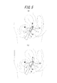
以上説明した本発明の一実施形態に係る膣内部支持具及び本発明の一実施形態に係る流体注入デバイスの構成によれば、例えば医師の診察により決定された、所望の量の空気が注入されるように調整操作部70の摘み71を操作することにより、注入部60の注入口61に送る空気の量を調整しておくことができる。そして、膣内部支持具1を、袋部40を適度に収縮させた状態にしておき、その膣内部支持具1の凹部31(接続部)に注入部60を接続し、膣内部支持具1のリング体30を、突出部Pの先端領域で押しながら突出部Pの先端領域と共に、図5(a)に示すように膣内へ挿入することができる。その際、挿入ガイド部50を膣壁に対して滑らせながら袋部40と共に膣内に挿入することができるため、膣内部支持具1の挿入を大幅に容易化することができる。
膣内部支持具1が膣内に挿入された状態で、流体注入デバイス2の注入操作部80を押し込めば、調整操作部70によって調整された量の空気を、注入部60の注入口61に圧送することができ、図4に示したように、開閉部20の逆止弁22を開き、空気を袋部40に流入させ、袋部40を膨張させることができる。その際、膣内部支持具1は、膣後壁側に配置された挿入ガイド部50によって、袋部40の膣後壁方向への膨張を抑制する一方で、袋部40の膣前壁方向への膨張を促進させる(袋部40の膨張方向を、膣入口側から膣奥側に向う方向と垂直な方向に対して、非対称に制御する)ことができる。
すなわち、流体注入デバイス2によって空気を袋部40に一様に流入させた際の袋部40の膨張方向を、膣前壁側を膣後壁側よりも大きく膨張させるように制御することができる。そして、袋部40の膣前壁側を膣後壁側よりも大きく膨張させることにより、図5(b)に示すように、袋部40の一部を、膣前壁における恥骨組織Cの子宮頸部N側近傍領域(すなわち、恥骨組織Cと子宮頸部Nとの間の領域のうち、子宮頸部Nよりも恥骨組織Cに近い領域)に押し込むことができる。その結果、袋部40の一部が、膣前壁を介して恥骨組織Cに係止されて、膣内部支持具1が膣内に確実に保持される。
また、ガイド部50が広範囲に膣後壁と接触するため、袋部40の膨張時の直腸の圧迫を緩和し、膣内部支持具1の使用に伴い生じる排便障害を軽減し、又は回避することができる。
また、ガイド部50が広範囲に膣後壁と接触するため、袋部40の膨張時の直腸の圧迫を緩和し、膣内部支持具1の使用に伴い生じる排便障害を軽減し、又は回避することができる。
そして、流体注入デバイス2のボタンBを押して、流体注入デバイス2と膣内部支持具1との係止を解除し、流体注入デバイス2の突出部Pの先端領域を膣内から除去することにより、図5に示すように、袋部40の一部を、膣前壁を介して恥骨組織Cに係止することができる。このように、袋部40の一部が膣前壁を介して恥骨組織Cに係止されていることにより、膣内部支持具1に膣奥側から膣入口側に向う方向に力が生じた場合であっても、膣入口側から膣奥側に向う方向の抗力を発生させることができる。したがって、膣内部支持具1を膣内に確実に保持すると共に、膣内部支持具1によって子宮頸部Nを下から支え、及び/または膣前壁の下垂を抑制し、及び/または膣後壁の下垂を抑制し、骨盤臓器脱を確実に抑制することが可能となる。
さらに、膣内部支持具1を膣内から取り出す際には、患者は、指でリング体30を所定の周方向位置で内側に圧迫することにより膣内部支持具1を収縮させ、挿入ガイド部50の凹み部W又はリング体30に指を引っ掛けて引き出すことができる。
なお、膣内部支持具1は、必ずしも前述した流体注入デバイス2を用いて膣内へ挿入する必要はなく、指でリング体30を膣奥側に向って押すことによって挿入することも可能である。その場合には、膣内部支持具1が膣内に挿入された状態で、前述した流体注入デバイス2の注入部60を膣内へ挿入し、注入口61を開閉部20に連通させて膣内部支持具1の袋部40を膨張させることができる。したがって、この場合には、流体注入デバイス2としては、前述したような、突出部Pを備える構成のものに限られず、例えば、注入口61と調整操作部70とをフレキシブルチューブで接続したような構成のものを採用することも可能である。
また、前述した膣内部支持具1に代えて、様々な変形例を採用することができる。
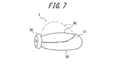
例えば、挿入ガイド部50は、図1~図2に示した例では、膣入口側から膣奥側に向って延びる楕円長皿形状をなしているが、このような形状に限られず、例えば、図6に示すように、膣入口側から膣奥側に向って、膣前壁方向に湾曲する楕円長皿形状とすることもできる。このような構造とすることにより、膣内部支持具1を膣奥まで挿入した際に、挿入ガイド部50の膣奥側部分が、膣入口側から膣奥側に向う方向よりも膣前壁方向に傾斜した状態となる。そのため、袋部40を膨張させる際に、前掲図5(a)及び(b)に示した恥骨組織Cの子宮頸部N側近傍領域に向う方向への袋部40の膨張を促進させることができる。また、図7に示すように、挿入ガイド部50に、袋部40の膣奥側端部全体を覆う、覆い部51を設けることもできる。この場合には、覆い部51の形状を予め調節しておくことによって、袋部40の膨張方向を膣前壁側へ制御することができる。なお、図6及び図7において、符号40を付した実線は膣内への挿入時の適度な収縮状態、二点鎖線は膣内への挿入後の膨張状態をそれぞれ示している。以下に参照する図8~図14においても、袋部40の状態を同様に示す。
また、図8又は図9に示すように、挿入ガイド部50を、軸を介して互いに回動可能な2つの部材によって形成することもできる。図8に示す例では、挿入ガイド部50を、膣入口側から膣奥側に向う方向と垂直な軸52を介して互いに回動可能な2つの部材53,54によって形成している。したがって、膣内部支持具1が膣奥に到達した際に、図8(b)の矢印で示すように、膣奥側の部材54が軸52の周りに膣後壁側から膣前壁側に向って回動するため、袋部40を膨張させる際に、袋部40の膣前壁方向への膨張を促進させることができる。また、膣入口から膣奥に至るまでの、膣内の挿入方向の角度の変化に合わせて挿入ガイド部50が変形可能となるため、膣内部支持具1の挿入時の違和感を軽減することができる。
図9に示す例では、挿入ガイド部50を、膣入口側から膣奥側に向う方向の軸52’を介して互いに回動可能な2つの部材53’,54’によって形成している。したがって、膣内部支持具1を膣内に挿入する際に、図9(a)に示す状態から、図9(b)の矢印で示すように、2つの部材53’,54’を軸52’の周りに回動させて折畳むことができ、膣内部支持具1全体の外径寸法を減少させることができるため、膣内部支持具1の膣内への挿入をより容易にすることができる。
また、図10に示すように、挿入ガイド部50の膣奥側の端部に、子宮頸部に適合可能な窪み部55が形成されるように構成してもよい。このような構成とした場合には、膣内部支持具1を膣内に挿入する際に、窪み部55で、下垂している子宮頸部を押し込みながら、膣内部支持具1全体を膣内に挿入することができる。
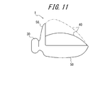
また、図11に示すように、挿入ガイド部50の膣入口側の端部に、前掲図5(a)及び(b)に示した恥骨組織Cに膣前壁を介して係止するための係止片56を形成することもできる。この場合には、袋部40の膨張時に、袋部40の膣前壁側領域で、膣前壁における恥骨組織Cの子宮頸部N側近傍領域を押し込み、係止片56及び膣前壁を介して恥骨組織Cに係止することができる。
また、図12に示すように、挿入ガイド部50に、袋部40を膨出させ、この膨出した袋部40を膣後壁に適合させる開口57を形成することによって、膣後壁の下垂を抑制し、直腸脱の治療効果を高めることができる。また、挿入ガイド部50に形成された開口57は、膣内部支持具1を膣内から取り出す際に、指を引っ掛けるための引っ掛け部として用いることもできる。
また、図13に示すように、挿入ガイド部50に、袋部40の膣前壁側領域の一部を覆う膨張抑制部58を設けることによって、袋部40の膨張時の形状を、患者の膣内形状により適合するように調節することや、前掲図5(a)及び(b)に示した恥骨組織Cに、膣前壁を介して嵌合可能な嵌合凹部Vを形成することができる。
さらに、図14に示すように、挿入ガイド部50を、袋部40の膣入口側端部から膣奥側端部まで袋部40の外表面に沿って蛇行する形状とし、挿入ガイド部50の膣入口側の端部はリング体30に一体化させ、挿入ガイド部50の膣奥側の端部には袋部の膣奥側端部を保持する袋保持部59を設けることもできる。このような構成とすることで、挿入ガイド部50全体に、挿入方向に対する伸縮性を与えることができる。そのため、下垂している子宮頸部を膣内に押し込みながら膣内部支持具1を膣内に挿入する際に、押し込まれる力を調整し、挿入時の違和感を軽減することができる。また、膣内部支持具1を膣内から取り出す際に、蛇行したいずれかの部分に指を引っ掛けることができるため、引っ掛け部分を手探りする手間を軽減し、膣内部支持具の膣内からの取り出しを容易にすることができる。また、挿入ガイド部50の材料費を低減させることもできる。
上述したところは、本発明の一実施形態を示したにすぎず、特許請求の範囲において、種々の変更を加えることができる。例えば、リング体30は、挿入ガイド部50の膣入口側の端部に連設されるものとして説明したが、必ずしもそのような構成に限られず、例えば、リング体30を袋部40の口部41に一体的に設け、挿入ガイド部50を袋部40の外表面に、例えば接着剤などによって接合することもできる。その場合には、膣内部支持具1を膣内へ挿入する際には、挿入ガイド部50の膣入口側の端部を指で膣奥側に向って押圧することにより、挿入ガイド部50で袋部40を膣内へ案内することができ、その結果、膣内部支持具1を膣内に挿入することができる。
1 膣内部支持具
2 流体注入デバイス
20 開閉部
21 貫通孔
22 逆止弁
30 リング体(押圧部)
31 凹部
31a 内周壁
40 袋部
41 口部
50 挿入ガイド部
51 覆い部
52,52’ 軸
53,53’,54,54’ 部材(挿入ガイド部)
55 窪み部
56 係止片
57 開口
58 膨張抑制部
59 袋保持部
60 注入部
60a 先端面
61 注入口
61a 環状突起
70 調整操作部
71 摘み
80 注入操作部
S 収納空間
W 凹み部
P 突出部
H 把持部
C 恥骨組織
B ボタン
N 子宮頸部
V 嵌合凹部
2 流体注入デバイス
20 開閉部
21 貫通孔
22 逆止弁
30 リング体(押圧部)
31 凹部
31a 内周壁
40 袋部
41 口部
50 挿入ガイド部
51 覆い部
52,52’ 軸
53,53’,54,54’ 部材(挿入ガイド部)
55 窪み部
56 係止片
57 開口
58 膨張抑制部
59 袋保持部
60 注入部
60a 先端面
61 注入口
61a 環状突起
70 調整操作部
71 摘み
80 注入操作部
S 収納空間
W 凹み部
P 突出部
H 把持部
C 恥骨組織
B ボタン
N 子宮頸部
V 嵌合凹部
Claims (11)
- 骨盤臓器脱を治療するための膣内に挿入された状態で膨張収縮可能な膣内部支持具において、
流体を通過させる開放状態と流体の通過を遮断する遮断状態との間で切り換え動作可能な開閉部と、
前記開閉部を介した流体の流入によって膨張可能であると共に、前記開閉部を介した流体の流出によって収縮可能である袋部と、
前記袋部の膣入口側端部から膣奥側端部まで該袋部の外表面の少なくとも一部に沿って延び、前記袋部を膣内に案内する挿入ガイド部と
を備えることを特徴とする膣内部支持具。 - 前記挿入ガイド部は、前記袋部の膣前壁方向への膨張を促進させる、請求項1に記載の膣内部支持具。
- 前記挿入ガイド部は、膣入口側から膣奥側に向って、膣前壁方向に湾曲している、請求項1又は2に記載の膣内部支持具。
- 前記挿入ガイド部は、前記袋部の膣奥側端部を覆う、覆い部を有する、請求項1~3のいずれか一項に記載の膣内部支持具。
- 前記挿入ガイド部は、軸を介して互いに回動可能な2つの部材によって形成されている、請求項1~4のいずれか一項に記載の膣内部支持具。
- 前記挿入ガイド部は、該挿入ガイド部の膣奥側の端部に、子宮頸部に適合可能な窪み部を有する、請求項1~5のいずれか一項に記載の膣内部支持具。
- 前記挿入ガイド部は、該挿入ガイド部の膣入口側の端部に、膣前壁を介して恥骨組織に係止するための係止片を有する、請求項1~6のいずれか一項に記載の膣内部支持具。
- 前記挿入ガイド部は、前記袋部を膨出させ、該膨出した袋部を膣後壁に適合させる開口を有する、請求項1~7のいずれか一項に記載の膣内部支持具。
- 前記開閉部を取り囲むリング状の押圧部を更に備え、
前記開閉部は、前記袋部への流体の流入を許容するが、前記袋部からの流体の流出は遮断する逆止弁とを有し、
前記逆止弁は、前記リング状の押圧部を所定の周方向位置で内側に圧迫することによって、前記袋部からの流体の流出を許容する、請求項1~8のいずれか一項に記載の膣内部支持具。 - 前記リング状の押圧部は、前記挿入ガイド部の膣入口側の端部に連設されている、請求項9に記載の膣内部支持具。
- 請求項1~10のいずれか一項に記載の膣内部支持具を膨張させるための流体注入デバイスであって、
前記膣内部支持具に接続し、前記開閉部に連通する注入口を有する注入部と、
前記注入部の注入口に送る流体の量を調整可能な調整操作部と、
前記調整操作部によって調整された量の流体を、前記注入部の注入口に圧送させる注入操作部と
を備えることを特徴とする流体注入デバイス。
Priority Applications (3)
| Application Number | Priority Date | Filing Date | Title |
|---|---|---|---|
| PCT/JP2013/002379 WO2014162364A1 (ja) | 2013-04-05 | 2013-04-05 | 膣内部支持具及び流体注入デバイス |
| JP2015509607A JP6068618B2 (ja) | 2013-04-05 | 2013-04-05 | 膣内部支持具及び膣内部支持具セット |
| US14/874,904 US11285036B2 (en) | 2013-04-05 | 2015-10-05 | Intravaginal support device, fluid injection device, and treating method for pelvic organ prolapse by use of intravaginal support device |
Applications Claiming Priority (1)
| Application Number | Priority Date | Filing Date | Title |
|---|---|---|---|
| PCT/JP2013/002379 WO2014162364A1 (ja) | 2013-04-05 | 2013-04-05 | 膣内部支持具及び流体注入デバイス |
Related Child Applications (1)
| Application Number | Title | Priority Date | Filing Date |
|---|---|---|---|
| US14/874,904 Continuation US11285036B2 (en) | 2013-04-05 | 2015-10-05 | Intravaginal support device, fluid injection device, and treating method for pelvic organ prolapse by use of intravaginal support device |
Publications (1)
| Publication Number | Publication Date |
|---|---|
| WO2014162364A1 true WO2014162364A1 (ja) | 2014-10-09 |
Family
ID=51657699
Family Applications (1)
| Application Number | Title | Priority Date | Filing Date |
|---|---|---|---|
| PCT/JP2013/002379 Ceased WO2014162364A1 (ja) | 2013-04-05 | 2013-04-05 | 膣内部支持具及び流体注入デバイス |
Country Status (3)
| Country | Link |
|---|---|
| US (1) | US11285036B2 (ja) |
| JP (1) | JP6068618B2 (ja) |
| WO (1) | WO2014162364A1 (ja) |
Cited By (3)
| Publication number | Priority date | Publication date | Assignee | Title |
|---|---|---|---|---|
| JP2018164726A (ja) * | 2017-03-28 | 2018-10-25 | クスヤマ合同会社 | 骨盤臓器脱の予防器具 |
| CN109350343A (zh) * | 2018-12-03 | 2019-02-19 | 黄达元 | 一种子宫托及其使用方法 |
| CN120753579A (zh) * | 2025-08-11 | 2025-10-10 | 四川省肿瘤医院 | 一种多方位扩阴器 |
Families Citing this family (3)
| Publication number | Priority date | Publication date | Assignee | Title |
|---|---|---|---|---|
| USD771254S1 (en) * | 2014-12-03 | 2016-11-08 | Ostara Biomedical Ltd | Animal pessary |
| EP4447857A1 (en) * | 2021-12-22 | 2024-10-23 | Corecreation UG (Haftungsbeschraenkt) | Device and system for prolapse alleviation and/or incontinence |
| JP2026510572A (ja) * | 2023-03-01 | 2026-04-08 | ノヴォカフ,インコーポレイテッド | 子宮頸部制御デバイス、子宮頸部制御システム、および、その使用のための方法 |
Citations (4)
| Publication number | Priority date | Publication date | Assignee | Title |
|---|---|---|---|---|
| US4669478A (en) * | 1985-03-21 | 1987-06-02 | Robertson Jack R | Device for diagnosing and relieving female incontinence |
| DE3700239A1 (de) * | 1986-03-18 | 1987-09-24 | Bischoff Ruediger Dr Med | Pessar |
| EP0663197A1 (de) * | 1994-01-13 | 1995-07-19 | Eckehard Dr. Hammersen | Aufblasbarer, ballonartiger Stützkörper |
| US6470890B1 (en) * | 2000-09-18 | 2002-10-29 | Ananias Diokno | Device and a method for mechanical installation and removal of inflatable vaginal pessary |
Family Cites Families (13)
| Publication number | Priority date | Publication date | Assignee | Title |
|---|---|---|---|---|
| US2101273A (en) * | 1935-01-09 | 1937-12-07 | Wallace D Smith | Massage instrument for treating the prostate gland |
| US2638093A (en) * | 1949-12-20 | 1953-05-12 | Kulick George | Vaginal insert |
| US4709690A (en) * | 1986-04-21 | 1987-12-01 | Habley Medical Technology Corporation | Implantable blood flow and occlusion pressure sensing sphincteric system |
| US5609559A (en) * | 1995-05-15 | 1997-03-11 | Weitzner; Howard B. | Device for female patients to prevent involuntary loss of urine |
| US5771899A (en) * | 1996-03-14 | 1998-06-30 | Bioteque America Inc. | Pessary |
| US5934279A (en) * | 1996-12-04 | 1999-08-10 | Lammers; Delmar R. | Pessary insertion apparatus |
| US7673631B2 (en) * | 2005-10-25 | 2010-03-09 | Ethicon, Inc. | Adjustable vaginal splint for pelvic floor support |
| WO2008079271A1 (en) * | 2006-12-21 | 2008-07-03 | Baystate Health, Inc. | Vaginal pessary |
| US8887731B2 (en) * | 2008-02-27 | 2014-11-18 | Ralph Zipper | Pessary device |
| US8651109B2 (en) * | 2008-04-23 | 2014-02-18 | Contipi Ltd. | Pessaries for prolapse alleviation |
| EP2413836B1 (en) * | 2009-03-30 | 2015-09-16 | Via TechMD LLC | Cervical stabilization device |
| WO2012006670A1 (en) * | 2010-07-13 | 2012-01-19 | Contiform International Pty Ltd | Intra-vaginal incontinence device and an applicator for same |
| EP2747703B1 (en) * | 2011-10-04 | 2017-07-19 | Gynamics Women's Health Ltd. | Female urinary incontinence device |
-
2013
- 2013-04-05 WO PCT/JP2013/002379 patent/WO2014162364A1/ja not_active Ceased
- 2013-04-05 JP JP2015509607A patent/JP6068618B2/ja active Active
-
2015
- 2015-10-05 US US14/874,904 patent/US11285036B2/en not_active Expired - Fee Related
Patent Citations (4)
| Publication number | Priority date | Publication date | Assignee | Title |
|---|---|---|---|---|
| US4669478A (en) * | 1985-03-21 | 1987-06-02 | Robertson Jack R | Device for diagnosing and relieving female incontinence |
| DE3700239A1 (de) * | 1986-03-18 | 1987-09-24 | Bischoff Ruediger Dr Med | Pessar |
| EP0663197A1 (de) * | 1994-01-13 | 1995-07-19 | Eckehard Dr. Hammersen | Aufblasbarer, ballonartiger Stützkörper |
| US6470890B1 (en) * | 2000-09-18 | 2002-10-29 | Ananias Diokno | Device and a method for mechanical installation and removal of inflatable vaginal pessary |
Cited By (3)
| Publication number | Priority date | Publication date | Assignee | Title |
|---|---|---|---|---|
| JP2018164726A (ja) * | 2017-03-28 | 2018-10-25 | クスヤマ合同会社 | 骨盤臓器脱の予防器具 |
| CN109350343A (zh) * | 2018-12-03 | 2019-02-19 | 黄达元 | 一种子宫托及其使用方法 |
| CN120753579A (zh) * | 2025-08-11 | 2025-10-10 | 四川省肿瘤医院 | 一种多方位扩阴器 |
Also Published As
| Publication number | Publication date |
|---|---|
| JPWO2014162364A1 (ja) | 2017-02-16 |
| US20160022475A1 (en) | 2016-01-28 |
| US11285036B2 (en) | 2022-03-29 |
| JP6068618B2 (ja) | 2017-01-25 |
Similar Documents
| Publication | Publication Date | Title |
|---|---|---|
| JP6068618B2 (ja) | 膣内部支持具及び膣内部支持具セット | |
| JP4824090B2 (ja) | 骨盤底支持のための調節可能な膣副子 | |
| US7036511B2 (en) | Vaginal pessary | |
| ES2621286T3 (es) | Dispositivo de refuerzo anatómico | |
| JP5059014B2 (ja) | 骨盤底支持のための調節可能な膣副子 | |
| JP5778242B2 (ja) | 便失禁のための膣内デバイス | |
| JP2014530678A (ja) | 便失禁を治療するための膣内デバイスおよび方法 | |
| US20070213661A1 (en) | Closure system for managing rectal or anal incontinence | |
| JP2003531645A (ja) | 自制式オストミー形成口 | |
| ES2686734T3 (es) | Sistema de esfínter urinario artificial que tiene un manguito con un balón inflable conectado a un bastidor | |
| JP2007529261A (ja) | 女性骨盤臓器脱出症治療装置 | |
| ES2842380T3 (es) | Dispositivo de incontinencia | |
| CN112040892A (zh) | 子宫梃子 | |
| CN108498146B (zh) | 宫颈环扎器 | |
| WO2014162363A1 (ja) | 膣内部支持具及び流体注入デバイス | |
| WO2014162362A1 (ja) | 膣内部支持具及び流体注入デバイス | |
| JP7832119B2 (ja) | 膣脱治療の為の膣デバイス | |
| JP7575653B2 (ja) | 開口部の拡張のためのバルーン | |
| JPH04276250A (ja) | 婦人失禁コントロール装置 | |
| AU2011227265B2 (en) | Intra-vaginal device for fecal incontinence | |
| ES2933569T3 (es) | Manguito conector | |
| ES2669197T3 (es) | Manguito para la uretra que incluye un tubo | |
| KR20250053359A (ko) | 자가 사용이 용이한 골반장기탈출증 치료용 페서리 | |
| HK40005910B (zh) | 尿失禁装置 |
Legal Events
| Date | Code | Title | Description |
|---|---|---|---|
| 121 | Ep: the epo has been informed by wipo that ep was designated in this application |
Ref document number: 13880940 Country of ref document: EP Kind code of ref document: A1 |
|
| ENP | Entry into the national phase |
Ref document number: 2015509607 Country of ref document: JP Kind code of ref document: A |
|
| NENP | Non-entry into the national phase |
Ref country code: DE |
|
| 122 | Ep: pct application non-entry in european phase |
Ref document number: 13880940 Country of ref document: EP Kind code of ref document: A1 |