WO2014156965A1 - アブレーションカテーテル - Google Patents
アブレーションカテーテル Download PDFInfo
- Publication number
- WO2014156965A1 WO2014156965A1 PCT/JP2014/057787 JP2014057787W WO2014156965A1 WO 2014156965 A1 WO2014156965 A1 WO 2014156965A1 JP 2014057787 W JP2014057787 W JP 2014057787W WO 2014156965 A1 WO2014156965 A1 WO 2014156965A1
- Authority
- WO
- WIPO (PCT)
- Prior art keywords
- catheter shaft
- electrode
- catheter
- shaft
- rotation transmission
- Prior art date
- Legal status (The legal status is an assumption and is not a legal conclusion. Google has not performed a legal analysis and makes no representation as to the accuracy of the status listed.)
- Ceased
Links
Images



Classifications
-
- A—HUMAN NECESSITIES
- A61—MEDICAL OR VETERINARY SCIENCE; HYGIENE
- A61B—DIAGNOSIS; SURGERY; IDENTIFICATION
- A61B18/00—Surgical instruments, devices or methods for transferring non-mechanical forms of energy to or from the body
- A61B18/04—Surgical instruments, devices or methods for transferring non-mechanical forms of energy to or from the body by heating
- A61B18/12—Surgical instruments, devices or methods for transferring non-mechanical forms of energy to or from the body by heating by passing a current through the tissue to be heated, e.g. high-frequency current
- A61B18/14—Probes or electrodes therefor
- A61B18/1492—Probes or electrodes therefor having a flexible, catheter-like structure, e.g. for heart ablation
-
- A—HUMAN NECESSITIES
- A61—MEDICAL OR VETERINARY SCIENCE; HYGIENE
- A61B—DIAGNOSIS; SURGERY; IDENTIFICATION
- A61B17/00—Surgical instruments, devices or methods
- A61B17/00234—Surgical instruments, devices or methods for minimally invasive surgery
- A61B2017/00292—Surgical instruments, devices or methods for minimally invasive surgery mounted on or guided by flexible, e.g. catheter-like, means
- A61B2017/003—Steerable
- A61B2017/00318—Steering mechanisms
-
- A—HUMAN NECESSITIES
- A61—MEDICAL OR VETERINARY SCIENCE; HYGIENE
- A61B—DIAGNOSIS; SURGERY; IDENTIFICATION
- A61B18/00—Surgical instruments, devices or methods for transferring non-mechanical forms of energy to or from the body
- A61B2018/00053—Mechanical features of the instrument of device
- A61B2018/00184—Moving parts
- A61B2018/0019—Moving parts vibrating
Definitions
- the present invention relates to an ablation catheter preferably used for the treatment of arrhythmia and the like.
- catheter ablation using a catheter is known.
- This treatment method is generally performed as follows. First, a long and flexible catheter shaft is inserted into a large blood vessel (eg, a femoral artery or a femoral vein) at the base of the foot, and its tip reaches the heart. Next, an electrocardiogram is measured while the electrode at the tip of the catheter shaft is in contact with the inner wall of the heart to search for an abnormal site.
- a large blood vessel eg, a femoral artery or a femoral vein
- a high-frequency (RF wave) current is generated from the electrode at the tip of the catheter shaft, the myocardium in the deep part is cauterized, and the cells at the site (lesion) causing the arrhythmia are necrotized.
- RF wave radio frequency
- the ablation area and the ablation depth it is generally difficult to control the ablation area and the ablation depth. For example, if the high frequency current output is too high, the inner wall of the heart may be punctured, or the electrode temperature may increase and a thrombus may occur.
- a thermistor for measuring the surface temperature of the inner wall of the heart is provided at the tip of the catheter shaft.
- the surface temperature detected through the thermistor exceeds a preset dangerous temperature, it is common practice to prevent excessive cauterization by reducing the high-frequency current output.
- Patent Document 1 describes an ablation catheter that vibrates the distal end of a catheter shaft and cools the distal end of the catheter shaft by blood flow generated thereby. With this method, the above-mentioned problem of the irrigation catheter does not occur.
- the tip of the catheter shaft is preferably small because it is inserted into the heart through the blood vessel. It is desirable to obtain the desired cooling effect by vibrating the tip of the catheter shaft without increasing the diameter of the tip of the catheter shaft.
- An object of the present invention is to provide an ablation catheter having a catheter shaft having a small diameter and capable of vibrating its tip.
- the ablation catheter of the present invention includes a catheter shaft having an electrode for cauterizing a living tissue at a tip thereof, a vibration generating mechanism in which an electrode device including the electrode is mounted and housed in the catheter shaft, and the catheter shaft A rotation transmission wire which is rotatably housed therein, one end of which is connected to the vibration generating mechanism, and the other end which is led out from the end of the catheter shaft.
- the rotation transmission wire transmits the rotational motion input to the other end thereof to the vibration generating mechanism.
- the vibration generating mechanism swings due to the rotational movement of the rotation transmission wire.
- the electrode vibrates by the oscillation of the vibration generating mechanism.
- the vibration generating mechanism on which the electrode device is mounted is housed in the catheter shaft, and the other end of the rotation transmission wire having one end connected to the vibration generating mechanism is led out from the end of the catheter shaft. Therefore, rotational movement can be input to the other end of the rotation transmission wire, and the vibration generating mechanism can be driven via the rotation transmission wire to vibrate the electrode. Since the rotational drive source that generates the rotational motion can be placed outside the catheter shaft, the constraints on the dimensions of the rotational drive source are relaxed. As a result, the desired cooling effect can be obtained by vibrating the tip electrode without increasing the diameter of the catheter shaft.
- FIG. 1 is a perspective view of an ablation catheter according to Embodiment 1 of the present invention.
- FIG. 2 is a perspective view showing the distal end of the catheter shaft of the ablation catheter according to the first embodiment of the present invention and the internal structure in the vicinity thereof.
- FIG. 3 is an exploded perspective view of the distal end of the catheter shaft of the ablation catheter according to the first embodiment of the present invention and the vicinity thereof.
- FIG. 4 is a perspective view of an electrode device and a vibration generating mechanism constituting the catheter shaft of the ablation catheter according to the first embodiment of the present invention.
- FIG. 5 is an exploded perspective view of the handle of the ablation catheter according to the first embodiment of the present invention.
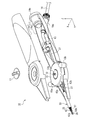
- FIG. 6 is a plan view for explaining an operation of bending the catheter shaft so that the distal electrode faces a desired direction in the ablation catheter according to the first embodiment of the present invention.
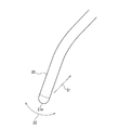
- FIG. 7 is a perspective view showing the relationship between the vibration direction of the electrode and the sweep direction when cauterizing the ablation surface using the ablation catheter according to the first embodiment of the present invention.
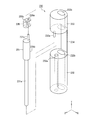
- FIG. 8 is an exploded perspective view conceptually showing the configuration of the vibration generating mechanism built in the catheter shaft of the ablation catheter according to the second embodiment of the present invention.
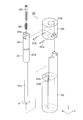
- FIG. 9 is an exploded perspective view conceptually showing the structure of the vibration generating mechanism built in the catheter shaft of the ablation catheter according to Embodiment 3 of the present invention.
- the present inventors Prior to the present invention, the present inventors have (1) a method for rotating an eccentric weight, (2) a method using a piezoelectric element, and (3) a method for bending a catheter shaft. The method of using the wire was examined.
- an eccentric weight is stored at the tip of the catheter shaft, and the eccentric weight is rotated.
- the mass of the eccentric weight and the amount of eccentricity are increased, the vibration energy generated is increased and the cooling effect is improved.
- the laminated piezoelectric element is housed at the tip of the catheter shaft.
- the tip of the catheter shaft is vibrated by applying a pulse voltage to the multilayer piezoelectric element to change the dimension of the multilayer piezoelectric element.
- the dimensional change amount of the laminated piezoelectric element is generally small, the amplitude of vibration generated at the distal end of the catheter shaft is small, and it is difficult to obtain an effective cooling effect.
- the present inventors examined a new method that can solve the problems of the above methods. As a result, a method of incorporating a vibration generating mechanism at the distal end of the catheter shaft and transmitting the rotational power from the outside of the catheter shaft to the vibration generating mechanism through the rotation transmission wire housed in the catheter shaft can achieve the above object. As a result, the present invention has been completed.
- the ablation catheter of the present invention includes a catheter shaft having an electrode for cauterizing a living tissue at a tip thereof, a vibration generating mechanism in which an electrode device including the electrode is mounted and housed in the catheter shaft, and the catheter shaft A rotation transmission wire which is rotatably housed therein, one end of which is connected to the vibration generating mechanism, and the other end which is led out from the end of the catheter shaft.
- the rotation transmission wire transmits the rotational motion input to the other end thereof to the vibration generating mechanism.
- the vibration generating mechanism swings due to the rotational movement of the rotation transmission wire.
- the electrode vibrates by the oscillation of the vibration generating mechanism.
- the ablation catheter of the present invention may further include a bending mechanism including at least one bending wire housed in the catheter shaft.
- the bending mechanism may bend and deform the catheter shaft so that the electrode faces a desired direction.
- the catheter shaft of the present invention can be bent and deformed so that the electrodes face the desired direction with a simple structure.
- the vibration generating mechanism and the rotation transmission wire are mechanically independent from the bending mechanism, a stable cooling effect can always be obtained regardless of the bending state of the catheter shaft by the bending mechanism.
- the direction in which the electrode vibrates may be substantially perpendicular to the direction in which the catheter shaft is bent and deformed by the bending mechanism. Accordingly, when the catheter shaft is bent using the bending mechanism and the electrode is swept along the longitudinal direction with the electrode pressed against the surface to be ablated, the direction in which the electrode vibrates is determined by the method of the surface to be ablated. When viewed along the line direction, it can be made substantially orthogonal to the electrode sweep direction.
- the vibration generating mechanism is preferably disposed on the electrode side with respect to the bending mechanism. Thereby, it can prevent that a catheter shaft enlarges by providing a vibration generating mechanism.
- the vibration generating mechanism may include a hinge spring that can be elastically bent and deformed, a swinging head that is held by the hinge spring, and a crank pin that is displaced along a circular orbit by a rotational motion of the rotation transmission wire. .
- a groove extending in a direction perpendicular to the bending surface of the hinge spring is formed in the swing head. It is preferable that the crank pin is engaged with the groove of the swing head.
- the ablation catheter of the present invention may further include a handle that holds the distal end of the catheter shaft, and a rotational drive source that outputs a rotational motion for rotating the rotation transmission wire.
- the rotational drive source may be disposed outside the handle. This configuration is advantageous in reducing the size and weight of the handle gripped by the practitioner because the rotational drive source is not housed in the handle. In addition, restrictions on the size and weight of the rotary drive source are further relaxed, which is advantageous for further improving the cooling effect.
- the rotation transmission wire may be rotatably accommodated in the protective tube.
- the rotation transmission wire housed in the protective tube may be housed in the catheter shaft. This prevents the rotation transmitting wire from contacting other members in the catheter shaft regardless of the curvature of the catheter shaft. This is advantageous in obtaining a stable cooling effect because the rotational power loss of the rotation transmission wire is reduced.
- FIG. 1 is a perspective view of an ablation catheter (hereinafter simply referred to as “catheter”) 1 according to Embodiment 1 of the present invention.
- the catheter 1 includes a handle 10 and a catheter shaft 20 held at one end of the handle 10 in the longitudinal direction.
- the handle 10 is a portion held by the practitioner and has a substantially bar shape as a whole.
- the catheter shaft 20 has the same length and outer diameter as a catheter shaft used in a conventional ablation catheter, and has flexibility to be freely curved.
- an intermediate portion of the catheter shaft 20 that extends linearly along the longitudinal direction of the handle 10 is omitted.
- an XYZ orthogonal coordinate system is set with the handle 10 and the axis parallel to the longitudinal direction of the catheter shaft 20 extended in a straight line as the Y axis.
- the Z axis is parallel to the rotation axis 12 (see FIG. 5, details will be described later) of the wire grip 15 provided on the handle 10.
- the electrode 27e side at the distal end of the catheter shaft 20 in the Y-axis direction is referred to as the “front” side or “tip” side, and the opposite side is referred to as the “rear” side or “end” side.
- the Z-axis direction is referred to as “vertical direction”, and the direction orthogonal to the Z-axis (direction parallel to the XY plane) is referred to as “horizontal direction”.
- the “vertical direction” and “horizontal direction” do not mean the direction when the catheter 1 is used.
- the portion near the electrode 27e of the catheter shaft 20 (the bent portion 21 in FIG. 6) is indicated by arrows 21a and 21b so that the electrode 27e at the distal end of the catheter shaft 20 faces a desired direction. It can be bent in the horizontal direction.
- the electrode 27e of the catheter shaft 20 can be vibrated in the vertical direction in the direction of the arrow 22.
- FIG. 2 is a perspective view of the distal end of the catheter shaft 20 and the vicinity thereof.
- a two-dot chain line 25 is a cylindrical cover that covers the catheter shaft 20.
- FIG. 2 shows the members housed in the cover 25 as seen through.
- the catheter shaft 20 includes an electrode device 27, a vibration generating mechanism 30, and a bending mechanism 40 in this order from the distal end side.
- the cover 25 is made of a flexible material (for example, a resin material) like the conventional catheter, and seals members in the catheter shaft 20 including the vibration generating mechanism 30 and the bending mechanism 40 in a liquid-tight manner from the outside.
- FIG. 3 is an exploded perspective view of members housed in the cover 25 at and near the distal end of the catheter shaft 20.
- FIG. 4 is a perspective view of the electrode device 27 and the vibration generating mechanism 30 as seen from a direction different from those in FIGS. In FIG. 4, the bending mechanism 40 is removed for easy understanding.
- the electrode device 27 is provided at the distal end of the catheter shaft 20.
- the electrode device 27 includes an electrode 27e at the tip thereof for applying a high-frequency current to the living tissue and cauterizing it.
- the electrode 27e is exposed to the outside at the tip of the catheter shaft 20 so as to be able to come into contact with living tissue.
- the electrode device 27 may include various sensors such as a pressure-sensitive sensor for detecting the presence or absence of a contact with a living tissue and a pressing force, a temperature sensor for detecting the ambient temperature, or the like.
- a known functional element may be provided in the ablation catheter.
- the vibration generating mechanism 30 that vibrates the electrode 27e of the catheter shaft 20 will be described.
- the vibration generating mechanism 30 according to the first embodiment includes a rotating shaft 31, a base 32, a swing head 33, and a hinge spring 34.
- the rotary shaft 31 includes an input shaft 31a, a shaft base 31b, and a crank pin 31c in this order from the rear side (the side opposite to the electrode device 27).
- the input shaft 31a is a rod-shaped member.
- the shaft base 31b has a cylindrical shape with a larger diameter than the input shaft 31a.
- the crank pin 31c is a rod-shaped member having a smaller diameter than the shaft base 31b.
- the input shaft 31a is coaxially connected to the shaft base 31b at the rear end of the shaft base 31b.
- the crank pin 31c is eccentrically connected to the front end of the shaft base 31b with respect to the input shaft 31a and the shaft base 31b.
- the base 32 has a substantially cylindrical shape.
- the base 32 is formed with two through holes 32a and 32b penetrating the base 32 in the axial direction (Y-axis direction).
- the input shaft 31a of the rotary shaft 31 is inserted into the bearing hole 32a which is one of the two through holes 32a and 32b, and the rotary shaft 31 is rotatably supported by the bearing hole 32a.
- the end of the input shaft 31 a of the rotary shaft 31 that protrudes rearward from the base 32 through the bearing hole 32 a is connected to the tip of the rotation transmission wire 36 using a sleeve 35.
- the rotation transmission wire 36 is rotatably accommodated in a flexible protective tube 37.
- the protective tube 37 is made of, for example, a flexible resin material.
- the rotation transmission wire 36 and the protective tube 37 in which the rotation transmission wire 36 is accommodated are accommodated in the cover 25 of the catheter shaft 20.
- the oscillating head 33 has a substantially cylindrical shape having substantially the same outer diameter as the base 32.
- the oscillating head 33 is formed with a through hole 33b penetrating the oscillating head 33 in the axial direction (Y-axis direction).
- An electrode device 27 is mounted on the end surface of the oscillating head 33 opposite to the base 32.
- a hinge spring 34 connects the base 32 and the swing head 33. More specifically, the rear end of the hinge spring 34 is fixed to a flat fixing surface 32 c formed on the outer surface of the base 32, and the front end of the hinge spring 34 is fixed to a flat fixing surface formed on the outer surface of the swing head 33. It is fixed to the surface 33c.
- the hinge spring 34 is a strip-shaped thin plate, and its longitudinal direction coincides with the longitudinal direction of the catheter shaft 20 and its main surface (that is, the surface having the largest area) is arranged parallel to the XY plane. Has been.
- the hinge spring 34 can be elastically bent and deformed in a plane (YZ plane; hereinafter referred to as “bend plane”) that is parallel to the longitudinal direction and perpendicular to the main surface. When the hinge spring 34 is bent and deformed, the swing head 33 swings with respect to the base 32 within the bent surface of the hinge spring 34.
- the rotating shaft 31 is disposed to face the main surface of the hinge spring 34.
- a groove (slot-shaped recess) extending along the direction (X-axis direction) perpendicular to the bent surface of the hinge spring 34 is formed on the end surface of the oscillating head 33 facing the base 32. 33a is formed. The crank pin 31c of the rotating shaft 31 is inserted into the groove 33a and engaged with the groove 33a.
- the rotation shaft 31 rotates in the same direction as the rotation transmission wire 36 in the bearing hole 32a of the base 32 via the sleeve 35.
- the crank pin 31c is eccentric with respect to the rotation center axis of the rotary shaft 31, the crank pin 31c is displaced along a circular orbit centering on the rotation center axis of the rotation shaft 31.
- the crank pin 31 c is inserted into the groove 33 a of the swing head 33. Therefore, of the displacement along the circular orbit of the crank pin 31c, the displacement in the direction perpendicular to the longitudinal direction of the groove 33a (Z-axis direction) is transmitted to the oscillating head 33.
- the crank pin 31c reciprocates in the groove 33a of the swing head 33 along the longitudinal direction (X-axis direction) of the groove 33a, while the swing head 33 is orthogonal to the groove 33a (Z-axis direction). Swing along.
- the hinge spring 34 repeatedly bends and deforms elastically within its bending surface.
- the vibration generating mechanism 30 of the first embodiment has the same configuration as a so-called scotch yoke mechanism, and the rotational motion input from the rotation transmission wire 36 to the input shaft 31a of the rotating shaft 31 It is converted into 33 swinging motions.
- the swing head 33 and the electrode device 27 vibrate in the up and down direction (in the direction of the arrow 22) at a constant cycle.
- the through hole 33 b of the swing head 33 and the through hole 32 b of the base 32 are arranged along a common straight line.
- a wiring (not shown) connected to the electrode device 27 is inserted into the through hole 33 b and the through hole 32 b, accommodated in the cover 25 of the catheter shaft 20, and guided to the handle 10.
- the bending mechanism 40 that bends the catheter shaft 20 so that the electrode 27e of the catheter shaft 20 faces a desired direction will be described.
- the bending mechanism 40 of the first embodiment includes a leaf spring 41 and a pair of bending wires 42a and 42b.
- the leaf spring 41 is a strip-shaped thin plate, the longitudinal direction of which coincides with the longitudinal direction of the catheter shaft 20, and its main surface (that is, the area is maximum). Are arranged in parallel with the YZ plane.
- the leaf spring 41 can be elastically bent and deformed in a plane (XY plane; hereinafter referred to as “bend plane”) that is parallel to the longitudinal direction and perpendicular to the main surface.
- the bending wires 42a and 42b are arranged on both sides of the leaf spring 41.
- the tips of the wires 42 a and 42 b on the base 32 side are fixed at positions near the front end 41 a of the leaf spring 41.
- the method for fixing the wires 42a and 42b to the leaf spring 41 is not particularly limited, but for example, a welding method can be used.
- the front end 41 a of the leaf spring 41 is inserted into the through hole 32 b of the base 32, and the rear end 41 b is inserted into the guide tube 43. Steps are formed on both sides of the leaf spring 41 so that the portions of both ends 41a and 41b of the leaf spring 41 are slightly narrower than the portion between them. This step restricts the insertion depth of the leaf spring 41 with respect to the base 32 and the guide tube 43.
- the wires 42 a and 42 b are accommodated in the guide tube 43.
- the wires 42 a and 42 b and the guide tube 43 storing the wires 42 a and 42 b are stored in the cover 25 of the catheter shaft 20. It is desirable that the guide tube 43 has a high rigidity with respect to compression and torsion along the longitudinal direction in addition to the flexibility that allows the guide tube 43 to be freely curved.
- the protective tube 37 that houses the rotation transmission wire 36 and the guide tube 43 that houses the wires 42 a and 42 b are housed in the cover 25.
- the opening at the tip of the cover 25 is liquid-tightly sealed by the electrode device 27.
- FIG. 5 is an exploded perspective view of the handle 10.
- the upper case 11a and the lower case 11b are overlapped in the Z-axis direction to form the housing 11 of the handle 10.
- a substantially disc-shaped wire grip 15 is accommodated in the housing 11 of the handle 10.
- a support shaft 12 erected in parallel with the Z axis on the inner surface of the lower case 11 b passes through the central through hole of the wire grip 15.
- a pair of operation arms 15 a and 15 b protrude from the outer peripheral edge of the wire grip 15.
- the operation arms 15a and 15b extend along a straight line orthogonal to the support shaft 12, and project outside the housing 11 through notches formed in the upper case 11a and the lower case 11b, respectively (see FIG. 1). .
- the wire grip 15 can be rotated around the support shaft 12 by operating the operation arms 15a and 15b.
- the catheter shaft 20 is sandwiched between the upper case 11a and the lower case 11b and led out from the front end of the handle 10. From the end of the cover 25 of the catheter shaft 20, a protective tube 37 containing the rotation transmission wire 36 and bending wires 42 a and 42 b are led out.
- the protective tube 37 containing the rotation transmission wire 36 passes through the space between the wire grip 15 and the lower case 11b, is guided by the guide 13, and reaches the first connector 19a provided on the lower surface of the lower case 11b. ing.
- One end of the rotation transmission cable 14 is detachably connected to the first connector 19a, and the other end of the rotation transmission cable 14 is connected to a rotation drive source 38 (see FIG. 1).
- the configuration of the rotational drive source 38 is arbitrary as long as it can output rotational motion.
- it can be configured by a motor as a power source and a gear mechanism that transmits power from the rotation shaft of the motor to the output end.
- the rotational drive source 38 may be controlled by the controller so that the rotational speed of the output rotational motion can be arbitrarily changed.
- the rotation transmission cable 14 has flexibility that can be freely bent, and transmits the rotation motion output from the rotation drive source 38 to the rotation transmission wire 36 via the first connector 19a.
- the bending wires 42 a and 42 b are fixed to the outer peripheral surface on the front side of the wire grip 15.
- the wire 42a is fixed to the wire grip 15 at a position close to the operation arm 15a
- the wire 42b is fixed to the wire grip 15 at a position close to the operation arm 15b.
- a male screw 12a is formed at the tip of the support shaft 12 that passes through the wire grip 15 and protrudes therefrom.
- a hole through which the support shaft 12 passes is formed in the upper case 11a.
- the male screw 12a of the support shaft 12 protrudes from the upper case 11a.
- a female screw (not shown) formed on the lower surface (surface on the wire grip 15 side) of the fixing knob 17 is screwed into the male screw 12 a of the support shaft 12.
- the second connector 19b is provided at the rear end of the handle 10.
- the wiring (not shown) connected to the electrode device 27 provided at the distal end of the catheter shaft 20 is led out from the end of the cover 25, passes through the space between the wire grip 15 and the lower case 11b, 2 is connected to the connector 19b.
- the power supply to the electrode 27e and the transmission and reception of electric signals to various sensors provided in the electrode device 27 are performed by electrically connecting the second connector 19b to a control device (not shown) via an electric cable (not shown). This is done by connecting to
- the catheter 1 of the first embodiment can be used as follows, for example, like the catheter of Patent Document 1 described above.
- the catheter shaft 20 is inserted into a thick blood vessel (for example, a femoral artery or a femoral vein) at the base of the patient's foot, and the electrode 27e at the tip thereof reaches the heart.
- a thick blood vessel for example, a femoral artery or a femoral vein
- the catheter shaft 20 is appropriately bent so that the electrode 27e at the tip of the catheter shaft 20 faces a desired direction.
- the catheter shaft 20 is bent by operating a pair of operation arms 15 a and 15 b protruding from the handle 10.
- FIG. 6 is a plan view of the catheter 1 with the upper case 11a and the fixed knob 17 removed for easy understanding.
- the bent portion 21 of the catheter shaft 20 is linear as shown by the solid line. It extends. Accordingly, the electrode 27e faces upward in FIG. 6 (the direction of the arrow on the Y axis).
- the portion (ie, the bent portion 21) in which the leaf spring 41 near the distal end of the catheter shaft 20 is built is bent in the direction of the arrow 21a as shown by the two-dot chain line 20a, and the electrode 27e is on the right side ( Face the arrow on the X axis).
- the bending angle of the catheter shaft 20 at the bending portion 21 can be adjusted by the rotation angle of the wire grip 15 (or the operation arms 15a and 15b) in the clockwise direction 16a.
- the portion (that is, the bent portion 21) in which the leaf spring 41 near the distal end of the catheter shaft 20 is built is bent in the direction of the arrow 21b as shown by the two-dot chain line 20b, and the electrode 27e is on the left side ( It faces the opposite side of the X-axis arrow.
- the bending angle of the catheter shaft 20 at the bending portion 21 can be adjusted by the rotation angle of the wire grip 15 (or the operation arms 15a and 15b) in the counterclockwise direction 16b.
- the wire grip 15 is sandwiched between the upper case 11a and the lower case 11b, or the fixing can be released.
- the operation knobs 15a and 15b are operated to turn the fixing knob 17 in a state where the bent portion 21 of the catheter shaft 20 is bent to a desired angle
- the wire grip 15 is fixed and the wire grip 15 is rotated. Can not be. Thereby, the bending angle of the bent portion 21 of the catheter shaft 20 can be maintained.
- the operation arms 15a and 15b are operated to appropriately bend the bent portion 21 of the catheter shaft 20, and the distal end of the catheter shaft 20 is inserted into the heart to search for an abnormal site in the inner wall of the heart.
- a high-frequency current is applied to the inner wall surface of the heart via the electrode 27e while the tip electrode 27e is in contact with the inner wall surface of the heart, thereby cauterizing the inner wall of the heart.
- the electrode 27e is vibrated. Thereby, the blood around the electrode 27e is agitated, and the temperature rise of the ablation site and the blood in the vicinity thereof is suppressed. In this manner, deep lesion tissue can be cauterized while appropriately controlling the temperature of the inner wall surface and the vicinity thereof.
- the vibration of the electrode 27e is performed by rotating the rotation transmission wire 36 using a rotation drive source 38.
- the rotational motion input to the end of the rotation transmission wire 36 is transmitted to the above-described vibration generating mechanism 30 via the rotation transmission wire 36, and the swing head 33 swings.
- the electrode 27e provided on the rocking head 33 vibrates in the Z-axis direction (the direction of the arrow 22 in FIG. 1).
- the cooling effect by vibrating the electrode 27e can be adjusted by changing the frequency of the electrode 27e, that is, the number of rotations of the rotation transmission wire 36.
- the catheter 1 of the first embodiment incorporates the vibration generating mechanism 30 that converts the rotational motion into vibration (oscillation motion) in the vicinity of the distal end of the catheter shaft 20.
- the rotational drive source 38 for driving the vibration generating mechanism 30 is disposed outside the catheter shaft 20, and the rotational motion generated by the rotational drive source 38 is transmitted through the rotation transmission wire 36 inserted into the catheter shaft 20. 30. Therefore, the electrode 27e at the tip can be vibrated without increasing the outer diameter of the catheter shaft 20.
- the cooling effect due to the vibration of the electrode 27e varies depending on the frequency and amplitude of the electrode 27e.
- the frequency of the electrode 27 e depends on the rotation speed of the rotation transmission wire 36. In order to increase the frequency of the electrode 27e, it is necessary to rotate the rotation transmission wire 36 at a high speed.
- the amplitude of the electrode 27e can be changed, for example, by adjusting the eccentric amount of the crank pin 31c with respect to the input shaft 31a of the rotary shaft 31, the distance from the crank pin 31c to the electrode 27e, and the like. In order to increase the frequency and amplitude of the electrode 27e, a drive source that generates large power is required.
- the rotational drive source 38 since the rotational drive source 38 is disposed outside the catheter shaft 20 and the handle 10, there are few restrictions on the dimensions of the rotational drive source 38. Therefore, it is easy to use the rotational drive source 38 having a high rotational speed and high output. As a result, the catheter 1 having a high cooling effect can be realized without increasing the diameter of the catheter shaft 20.
- the rotational drive source 38 being arranged outside the handle 10 is advantageous in improving the operability of the catheter 1 and reducing the burden on the operator because the handle 10 is reduced in size and weight. .
- the vibration generating mechanism 30 and the rotation transmission wire 36 for vibrating the electrode 27e are mechanically independent from the bending mechanism 40 for bending the catheter shaft 20. Therefore, by providing the function of vibrating the electrode 27e, the basic characteristic required for the catheter, that is, bending the catheter shaft 20 so that the electrode 27e faces the desired direction, is not impaired. Further, the vibration generating mechanism 30 can be disposed on the electrode 27e side of the bending mechanism 40 along the longitudinal direction of the catheter shaft 20, which is to avoid an increase in the diameter of the catheter shaft 20. It is advantageous.
- the rotation transmission wire 36 accommodated in the catheter shaft 20 is also bent according to the curve of the catheter shaft 20. Since the rotation transmission wire 36 is accommodated in the protective tube 37, the rotation transmission wire 36 contacts other members (for example, the cover 25, the guide tube 43, etc.) regardless of the curvature of the catheter shaft 20. Avoided. Therefore, the rotational power loss of the rotation transmission wire 36 is reduced, and a stable cooling effect is always obtained regardless of the curved state of the catheter shaft 20.
- the inventors have already prototyped a catheter 1 having a catheter shaft 20 having an electrode device 27 and a cover 25 with an outer diameter of ⁇ 2.4 mm. ing.
- the rotation transmission wire 36 is accommodated in the small-diameter cover 25 together with the guide tube 43 accommodating the bending wires 42a and 42b and the electric wiring. Therefore, it is desirable that the rotation transmission wire 36 has the smallest possible diameter. Furthermore, since the rotation transmission wire 36 needs to transmit a rotational motion over a relatively long distance that is almost equal to or longer than the entire length of the catheter shaft 20, rotation followability (when one end is rotated, the other end is rotated by one end). It is desirable to have excellent torque transmission characteristics and characteristics that immediately rotate as much as possible. Furthermore, the rotation transmission wire 36 is also desired to have a high rust prevention characteristic and a flexibility that can be freely bent.
- the rotation transmission wire 36 satisfying such a request is not particularly limited, but for example, a DMC spin rope having an outer diameter of about ⁇ 0.30 mm to ⁇ 0.90 mm can be used.
- the main surface of the leaf spring 41 constituting the bending mechanism 40 and the main surface of the hinge spring 34 constituting the vibration generating mechanism 30 are orthogonal to each other (FIGS. 2 and 3). Therefore, as shown in FIG. 1, the bending directions 21a and 21b of the catheter shaft 20 by the bending mechanism 40 and the vibration direction 22 of the electrode 27e by the vibration generating mechanism 30 are orthogonal to each other. In this configuration, as shown in FIG. 7, when the catheter shaft 20 is bent and the electrode 27e is pressed against the ablation surface (not shown), the catheter shaft 20 is swept along the longitudinal direction D1.
- the direction 22 in which the electrode 27e vibrates is substantially orthogonal to the sweep direction D1 of the electrode 27e when viewed along the normal direction of the surface to be ablated.
- This is advantageous for improving the ablation efficiency and avoiding local abnormal heating.
- since the possibility that the electrode 27e repeats contact and separation with respect to the surface to be ablated is reduced by vibrating the electrode 27e, more stable cauterization can be performed.
- the stirring effect of the blood around the electrode 27e when the electrode 27e is vibrated increases, a higher cooling effect can be obtained.
- the second embodiment is different from the first embodiment regarding the configuration of the vibration generating mechanism built in the catheter shaft 20.
- the catheter of the second embodiment will be described focusing on differences from the first embodiment.
- FIG. 8 is an exploded perspective view conceptually showing the vibration generating mechanism 230 of the second embodiment.
- the vibration generating mechanism 230 according to the second embodiment includes a rotation shaft 231, a base 232, a swing head 233, a hinge spring 234, and a connecting member 235.
- the rotation shaft 231 includes an input shaft 231a, a shaft base 231b, and a crank pin 231c in this order from the handle 10 side (lower side in FIG. 8), similarly to the rotation shaft 31 of the first embodiment.
- the input shaft 231a and the shaft base 231b are connected coaxially, and the crank pin 231c is eccentrically connected to these and connected to the shaft base 231b.
- a base 232 and a swing head 233 are connected via a hinge spring 234.
- the hinge spring 234 can be elastically bent and deformed in a bending plane parallel to the YZ plane.
- An input shaft 231a is inserted into a bearing hole 232a that penetrates the base 232, and the rotary shaft 231 is rotatably supported by the bearing hole 232a.
- the end of the input shaft 231a that protrudes from the base 232 through the bearing hole 232a is connected to a rotation transmission wire 36 (not shown) as in the first embodiment.
- the connecting pin 233a protrudes from the surface of the oscillating head 233 facing the base 232.
- the connecting member 235 two through holes 235a and 235b having different positions on the XZ plane are formed.
- a crank pin 231c is inserted into the first through hole 235a, and a connecting pin 233a is inserted into the second through hole 235b.
- the crank pin 231c When the rotation shaft 231 rotates in one direction via the rotation transmission wire 36, the crank pin 231c is displaced along a circular orbit centering on the rotation center axis of the rotation shaft 231.
- the connecting member 235 transmits the displacement in the direction parallel to the bent surface of the hinge spring 234 (Z-axis direction) out of the displacement along the circular orbit of the crank pin 231c to the connecting pin 233a.
- the swing head 233 swings in the Z-axis direction.
- the hinge spring 234 repeats elastic deformation in the bending surface.
- the vibration generating mechanism 230 of the second embodiment has a so-called crank mechanism, and the rotational motion input from the rotation transmission wire 36 to the input shaft 231a of the rotational shaft 231 is converted into the swing motion of the swing head 233. Convert to By continuously rotating the rotation transmission wire 36 at a constant rotational speed, an electrode device 27 (not shown) mounted on the rocking head 233 vibrates at a constant cycle.
- the wiring connected to the electrode device 27 is inserted into the through hole 232b of the base 232 and the through hole 233b of the swing head 233.
- the catheter of the second embodiment is configured using the vibration generation mechanism 230 described above instead of the vibration generation mechanism 30 of the catheter 1 of the first embodiment. Also in the catheter of the second embodiment, a vibration generating mechanism 230 that converts rotational motion into vibration (oscillation motion) is built in the vicinity of the distal end of the catheter shaft 20. Therefore, as in the first embodiment, the electrode 27e at the tip can be vibrated without increasing the outer diameter of the catheter shaft 20.
- the second embodiment is the same as the first embodiment except for the above, and has the same effect as the first embodiment.
- the third embodiment is different from the first embodiment regarding the configuration of the vibration generating mechanism built in the catheter shaft 20.
- the catheter of the third embodiment will be described focusing on differences from the first embodiment.
- FIG. 9 is an exploded perspective view conceptually showing the vibration generating mechanism 330 of the third embodiment.
- the vibration generating mechanism 330 according to the third embodiment includes a rotation shaft 331, a base 332, a swing head 333, a slide cam 334, a connection screw 335, a compression coil spring 336, a first swing pin 337a, and a second swing pin 337b. .
- the rotating shaft 331 includes an input shaft 331a and a shaft base 331b in this order from the handle 10 side (lower side in FIG. 9).
- the input shaft 331a and the shaft base 331b are connected coaxially.
- a slide cam 334 is arranged coaxially with the rotation shaft 331 and facing the rotation shaft 331 in the axial direction.
- Helical cam surfaces are respectively formed on end surfaces of the shaft base portion 331b and the slide cam 334 facing each other.
- the spiral cam surface has a continuous inclined surface that gradually rises over a rotation range of 360 degrees with respect to the central axis, and the top (end) of the inclined surface is the bottom of the inclined surface through a step (drop). Adjacent to (starting edge).
- the compression coil spring 336 and the connecting screw 335 are inserted in this order into the through hole 334a penetrating the slide cam 334 in the axial direction from the side opposite to the rotating shaft 331.
- the connection screw 335 passes through the compression coil spring 336 and the slide cam 334 in order, and is screwed to the rotary shaft 331. As a result, the compression coil spring 336 biases the slide cam 334 toward the rotating shaft 331.
- the input shaft 331a is inserted into the bearing hole 332a penetrating the base 332, and the rotating shaft 331 is rotatably supported by the bearing hole 332a.
- the end of the input shaft 331a that protrudes from the base 332 through the bearing hole 332a is connected to the rotation transmission wire 36 (not shown) as in the first embodiment.
- Each of them has a base 332 having a substantially cylindrical outer peripheral surface and a swing head 333 connected via a first swing pin 337a.
- the swing head 333 can swing with respect to the base 332 about the first swing pin 337a.
- the slide cam 334 is connected to the swing head 333 via the second swing pin 337b.
- the swing head 333 can swing with respect to the slide cam 334 around the second swing pin 337b.
- the second swing pin 337b is parallel to the first swing pin 337a.
- Rotation shaft 331 rotates in the direction of arrow R via rotation transmission wire 36.
- the slide cam 334 cannot be rotated because it is connected to the swing head 333 via the second swing pin 337b. Therefore, the spiral cam surface formed on the slide cam 334 slides on the spiral cam surface formed on the shaft base 331b of the rotary shaft 331.
- the slide cam 334 moves away from the rotary shaft 331.
- the top of the spiral cam surface of the slide cam 334 exceeds the top of the spiral cam surface of the shaft base 331b.
- the slide cam 334 is displaced toward the rotating shaft 331 by the biasing force of the compression coil spring 336.
- the slide cam 334 reciprocates along the rotation axis direction of the rotation shaft 331.
- the swing head 333 connected to the slide cam 334 swings with respect to the base 332 about the first swing pin 337a.
- the vibration generating mechanism 330 converts the rotary motion input from the rotation transmission wire 36 to the input shaft 331a of the rotary shaft 331 into the swing motion of the swing head 333.
- an electrode device 27 (not shown) mounted on the rocking head 333 vibrates at a constant cycle.
- the wiring connected to the electrode device 27 is inserted into the through hole 332b of the base 332 and the through hole 333b of the swing head 333.
- the catheter of the third embodiment is configured using the vibration generation mechanism 330 described above instead of the vibration generation mechanism 30 of the catheter 1 of the first embodiment. Also in the catheter of the third embodiment, a vibration generating mechanism 330 that converts rotational motion into vibration (oscillation motion) is built in the vicinity of the distal end of the catheter shaft 20. Therefore, as in the first embodiment, the electrode 27e at the tip can be vibrated without increasing the outer diameter of the catheter shaft 20.
- the third embodiment is the same as the first embodiment except for the above, and has the same effect as the first embodiment.
- the spiral cam surfaces are formed on the surfaces of the rotating shaft 331 and the slide cam 334 facing each other, but the shape of the cam surface is not limited to this and can be arbitrarily set.
- the cam surface may be a smooth curved surface whose position in the Y-axis direction changes in a sine wave shape along the circumference surrounding the central axis. It is not necessary that cam surfaces having the same shape are formed on both surfaces of the rotating shaft 331 and the slide cam 334 facing each other.
- One of the rotating shaft 331 and the slide cam 334 is formed with a cam surface having a predetermined shape on the surface facing the other, and the other is formed with a protrusion (cam) that slides on the one cam surface. It may be. In this case, the slide cam 334 may be omitted, and the protrusion (cam) may be formed directly on the swing head 333.
- the means for urging the slide cam 334 toward the rotating shaft 331 is not limited to the compression coil spring 336.
- the base 332 and the swinging head 333 are connected using a plate spring similar to the hinge springs 34 and 234 shown in the first and second embodiments, and the slide cam 334 is connected to the rotary shaft using the elastic force of the plate spring. You may bias toward 331.
- the direction 22 in which the electrode 27e vibrates by the vibration generating mechanisms 30, 230, 330 is perpendicular to the directions 21a, 21b in which the bent portion 21 of the catheter shaft 20 is bent by the bending mechanism 40. (See FIG. 1).
- the vibration direction 22 of the electrode 27e does not need to be perpendicular to the bending directions 21a and 21b of the catheter shaft 20, and may be parallel, for example, or may be inclined at any other angle.
- the vibration generating mechanisms 30, 230, and 330 are rotated with respect to the bending mechanism 40 so that the operator can arbitrarily set the vibration direction 22 of the electrode 27e with respect to the bending directions 21a and 21b of the catheter shaft 20.
- the vibration direction 22 of the electrode 27e relative to the bending directions 21a, 21b of the catheter shaft 20 can be arbitrarily set. it can.
- the configuration of the vibration generating mechanism is not limited to the above first to third embodiments. Any mechanism that can convert the rotational motion of the rotation transmission wire 36 into oscillation (vibration) can be employed. However, since the vibration generating mechanism 30 using the Scotch yoke mechanism shown in the first embodiment has a small number of parts and a simple structure, it is excellent in reliability and durability.
- the handle 10 is provided with the first connector 19a for transmitting the rotational motion and the second connector 19b for electrical connection. Transmission of rotational motion and electrical connection may be performed.
- the common connector is detachably connected to a single cable for transmitting rotational power and transmitting / receiving electrical signals. According to this configuration, the number of cables connected to the handle 10 can be reduced.
- the rotation drive source 38 may be accommodated in the handle 10. According to this configuration, the first connector 19a and the rotation transmission cable 14 (see FIG. 1) for transmitting rotational power are not necessary.
- the configuration of the bending mechanism for bending the catheter shaft 20 is not limited to the first to third embodiments.
- one of the two wires 42a and 42b can be omitted.
- the wire 42a when tension is applied to the wire 42a, the wire 42a is pulled out from the catheter shaft 20, the bent portion 21 bends in the direction of the arrow 21a (see FIG. 1), and when the tension is released, the wire 42a The bent portion 21 returns to the initial state by being pulled into the catheter shaft 20 by the elastic recovery force.
- a bending mechanism known as a catheter can be applied to the catheter of the present invention.
- the present invention can be widely used as an ablation catheter for cauterizing living tissue. Especially, it can utilize preferably in order to cauterize the heart wall and treat an arrhythmia. However, it can also be used to cauterize parts other than the heart wall (for example, the sympathetic nerve of the renal artery).
Landscapes
- Health & Medical Sciences (AREA)
- Life Sciences & Earth Sciences (AREA)
- Surgery (AREA)
- Engineering & Computer Science (AREA)
- Plasma & Fusion (AREA)
- Medical Informatics (AREA)
- Otolaryngology (AREA)
- Physics & Mathematics (AREA)
- Cardiology (AREA)
- Biomedical Technology (AREA)
- Heart & Thoracic Surgery (AREA)
- Nuclear Medicine, Radiotherapy & Molecular Imaging (AREA)
- Molecular Biology (AREA)
- Animal Behavior & Ethology (AREA)
- General Health & Medical Sciences (AREA)
- Public Health (AREA)
- Veterinary Medicine (AREA)
- Surgical Instruments (AREA)
Abstract
カテーテルシャフト(20)内に、生体組織を焼灼するための電極(27e)を含む電極装置(27)が搭載された振動発生機構(30)が収納されている。回転伝達ワイヤ(36)の一端が振動発生機構(30)に接続され、その他端がカテーテルシャフト(20)の末端から導出されている。回転伝達ワイヤ(36)は、その他端に入力された回転運動を振動発生機構(30)に伝達し、振動発生機構(30)は回転伝達ワイヤ(36)の回転運動により揺動し、振動発生機構(30)の揺動により電極(27e)が振動する。
Description
本発明は、不整脈の治療等に好ましく使用されるアブレーションカテーテルに関する。
頻脈性不整脈の治療方法の一つとして、カテーテル(一般に「アブレーションカテーテル」と呼ばれる)を用いたカテーテルアブレーション術が知られている。この治療方法は、概略、以下のように行われる。最初に、長尺且つ柔軟なカテーテルシャフトを足の付け根にある太い血管(例えば大腿動脈又は大腿静脈)に挿入し、その先端を心臓内に到達させる。次いで、カテーテルシャフトの先端の電極を心臓の内壁に接触させながら心電図を計測し、異常部位を探索する。異常部位が見つかると、カテーテルシャフトの先端の電極から高周波(RF波)電流を発生させ、深部にある心筋を焼灼し、不整脈発生の原因となっている部位(病巣)の細胞を壊死させる。
このカテーテルアブレーション術では、焼灼面積や焼灼深さを制御することは一般に難しい。例えば、高周波電流出力が高すぎると、心臓内壁を穿孔してしまったり、電極温度が高くなり血栓が生じたりする。
カテーテルシャフトの先端には、心臓内壁の表面温度を測定するためのサーミスタが設けられている。サーミスタを通じて検出された表面温度があらかじめ設定した危険温度を越えると、高周波電流出力を低下させることで、過剰焼灼を防止することが一般に行われている。
ところが、このような心臓内壁の表面温度制御を行うと、表面のみが焼灼されて、深部の病巣を焼灼できないという問題が生じることがある。
そこで、心臓内壁表面を冷却することで表面のみが焼灼されるのを回避しながら、深部の病巣を焼灼する手法が検討されている。
その一手法として、先端に冷却用の生理食塩水を吹き出す孔を設けたイリゲーションカテーテルを用いる方法がある。ところが、この方法は、心臓内壁表面に対するカテーテルシャフトの向きによっては冷却効果にムラが生じる、生理食塩水を用いるので心不全や腎臓障害を有する患者には不向きである、生理食塩水を供給するためのポンプが必要であるので装置が大型且つ高価である、などの問題を有している。
特許文献1には、カテーテルシャフトの先端を振動させ、これにより生じる血流により、カテーテルシャフトの先端を冷却させるアブレーションカテーテルが記載されている。この手法であれば、イリゲーションカテーテルが有する上述した問題は生じない。
カテーテルシャフトの先端は、血管を通って心臓内に挿入されるから、小径であることが望ましい。カテーテルシャフトの先端を大径化することなく、カテーテルシャフトの先端を振動させて、所望する冷却効果を得ることが望まれる。
本発明は、小径でその先端が振動可能なカテーテルシャフトを備えたアブレーションカテーテルを提供することを目的とする。
本発明のアブレーションカテーテルは、生体組織を焼灼するための電極をその先端に有するカテーテルシャフトと、前記電極を含む電極装置が搭載され且つ前記カテーテルシャフト内に収納された振動発生機構と、前記カテーテルシャフト内に回転可能に収納され、その一端が前記振動発生機構に接続され、その他端が前記カテーテルシャフトの末端から導出された回転伝達ワイヤとを備える。前記回転伝達ワイヤは、その前記他端に入力された回転運動を前記振動発生機構に伝達する。前記振動発生機構は、前記回転伝達ワイヤの回転運動により揺動する。前記振動発生機構の揺動により前記電極が振動する。
本発明によれば、電極装置を搭載する振動発生機構がカテーテルシャフト内に収納され、一端が振動発生機構に接続された回転伝達ワイヤの他端がカテーテルシャフトの末端から導出されている。従って、回転運動を回転伝達ワイヤの他端に入力し、回転伝達ワイヤを介して振動発生機構を駆動して、電極を振動させることができる。回転運動を発生させる回転駆動源をカテーテルシャフトの外に配置することができるので、回転駆動源の寸法に関する制約が緩和される。その結果、カテーテルシャフトを大径化することなく、先端の電極を振動させて所望する冷却効果を得ることができる。
本発明者らは、本発明に先立って、カテーテルシャフトの先端を振動させる方法として、(1)偏心錘を回転させる方法、(2)圧電素子を用いる方法、(3)カテーテルシャフトを屈曲させるためのワイヤを利用する方法などを検討した。
方法(1)では、カテーテルシャフトの先端に偏心錘を収納し、当該偏心錘を回転させる。偏心錘の質量及び偏心量を大きくするほど、発生する振動エネルギーが大きくなり、冷却効果が向上する。しかしながら、所望する冷却効果を得るために必要な質量及び偏心量を有する偏心錘を、小さな外径を有するカテーテルシャフトの先端に収納することは困難である。
方法(2)では、積層型圧電素子をカテーテルシャフトの先端に収納する。積層型圧電素子にパルス状電圧を印加して積層型圧電素子を寸法変化させることにより、カテーテルシャフトの先端を振動させる。しかしながら、積層型圧電素子の寸法変化量は一般に小さいので、カテーテルシャフトの先端に発生する振動の振幅は小さく、有効な冷却効果を得ることは困難である。
方法(3)では、カテーテルシャフトを屈曲させてその先端の向きを変えるためにカテーテルシャフトに一般的に内蔵されているワイヤを高速で交互に緊張及び弛緩させる。これにより、カテーテルシャフトの先端を屈曲振動させることができる。この方法は、上記の方法(1)及び(2)と異なり、カテーテルシャフトの先端に振動を発生させるための機構を新たに収納する必要がないので、カテーテルシャフトの先端の外径を小さくすることができる。しかしながら、カテーテルシャフトの屈曲及び振動の両方を行うために共通するワイヤを使用するので、ワイヤを引っ張ってカテーテルシャフトを屈曲させた状態では、ワイヤを交互に緊張及び弛緩させても、カテーテルシャフトの先端に発生する振動の振幅が著しく小さくなってしまい、所望する冷却効果が得られない。
本発明者らは、上記の各方法が有する課題を解決しうる新たな方法を検討した。その結果、カテーテルシャフトの先端に振動発生機構を内蔵させ、カテーテルシャフト内に収納した回転伝達ワイヤを通じてカテーテルシャフト外から振動発生機構に回転動力を伝達する方法が、上記の目的を達成することができることを見出して、本発明を完成するに至った。
本発明のアブレーションカテーテルは、生体組織を焼灼するための電極をその先端に有するカテーテルシャフトと、前記電極を含む電極装置が搭載され且つ前記カテーテルシャフト内に収納された振動発生機構と、前記カテーテルシャフト内に回転可能に収納され、その一端が前記振動発生機構に接続され、その他端が前記カテーテルシャフトの末端から導出された回転伝達ワイヤとを備える。前記回転伝達ワイヤは、その前記他端に入力された回転運動を前記振動発生機構に伝達する。前記振動発生機構は、前記回転伝達ワイヤの回転運動により揺動する。前記振動発生機構の揺動により前記電極が振動する。
上記の本発明のアブレーションカテーテルが、前記カテーテルシャフト内に収納された少なくとも1本の屈曲用ワイヤを含む屈曲機構を更に備えてもよい。この場合、前記カテーテルシャフトの前記末端から導出された前記少なくとも1本の屈曲用ワイヤが引っ張られると、前記屈曲機構は、前記電極が所望する向きに向くように前記カテーテルシャフトを屈曲変形させることが好ましい。これにより、簡単な構造により、電極が所望する向きに向くように本発明のカテーテルシャフトを屈曲変形させることができる。また、振動発生機構及び回転伝達ワイヤは、屈曲機構とは機構上独立しているので、屈曲機構によるカテーテルシャフトの屈曲状態とは無関係に常に安定した冷却効果を得ることができる。
上記において、前記電極が振動する方向が、前記屈曲機構によって前記カテーテルシャフトが屈曲変形する方向に対して略垂直であってもよい。これにより、屈曲機構を用いてカテーテルシャフトを屈曲させて電極を被焼灼面に押し当てた状態でカテーテルシャフトをその長手方向に沿って掃引する場合、電極が振動する方向を、被焼灼面の法線方向に沿って見たときに電極の掃引方向に対して略直交させることができる。
前記振動発生機構は、前記屈曲機構に対して前記電極側に配置されていることが好ましい。これにより、振動発生機構を備えることによってカテーテルシャフトが大径化するのを防ぐことができる。
前記振動発生機構は、弾性的に屈曲変形可能なヒンジバネと、前記ヒンジバネによって保持された揺動ヘッドと、前記回転伝達ワイヤの回転運動により、円軌道に沿って変位するクランクピンとを備えてもよい。この場合、前記揺動ヘッドには、前記ヒンジバネの屈曲面に垂直な方向に沿って延びた溝が形成されていることが好ましい。前記クランクピンが前記揺動ヘッドの前記溝に係合していることが好ましい。これにより、いわゆるスコッチヨーク機構が構成され、回転運動を揺動ヘッドの揺動運動(振動)に変換する、簡単且つ高信頼性の振動発生機構を実現することができる。
上記の本発明のアブレーションカテーテルが、前記カテーテルシャフトの前記末端を保持するハンドルと、前記回転伝達ワイヤを回転させるための回転運動を出力する回転駆動源とを更に備えてもよい。この場合、前記回転駆動源は、前記ハンドルの外に配置されていてもよい。この構成は、ハンドル内に回転駆動源が収納されないので、施術者が把持するハンドルの小型化且つ軽量化に有利である。また、回転駆動源の寸法や重量に関する制約が更に緩和されるので、冷却効果を更に向上させるのに有利である。
前記回転伝達ワイヤは、保護チューブ内に回転可能に収納されてもよい。この場合、前記保護チューブ内に収納された前記回転伝達ワイヤが前記カテーテルシャフト内に収納されていてもよい。これにより、カテーテルシャフトの湾曲の如何に関わらず、回転伝達ワイヤがカテーテルシャフト内の他の部材に接触するのが回避される。これは、回転伝達ワイヤの回転動力損失が低減されるので、安定した冷却効果を得るのに有利である。
以下に、本発明を好適な実施形態を示しながら詳細に説明する。但し、本発明は以下の実施形態に限定されないことはいうまでもない。以下の説明において参照する各図は、説明の便宜上、本発明の実施形態を構成する部材のうち、本発明を説明するために必要な主要部材のみを簡略化して示したものである。従って、本発明は以下の各図に示されていない任意の部材を備え得る。また、以下の各図では、実際の部材の寸法および各部材の寸法比率等は忠実に表されていない。
(実施形態1)
図1は、本発明の実施形態1にかかるアブレーションカテーテル(以下、単に「カテーテル」という)1の斜視図である。カテーテル1は、ハンドル10と、ハンドル10の長手方向の一端に保持されたカテーテルシャフト20とを備える。ハンドル10は、施術者が保持する部分であり、全体として略棒状形状を有する。カテーテルシャフト20は、従来のアブレーションカテーテルに使用されるカテーテルシャフトと同程度の長さ及び外径を有するとともに、自由に湾曲させることができる柔軟性を有している。図面を簡単化するために、図1では、ハンドル10の長手方向に沿って直線状に延ばされたカテーテルシャフト20の中間部分を省略している。以下の説明の便宜のために、ハンドル10及び一直線に延ばされたカテーテルシャフト20の長手方向に平行な軸をY軸とするXYZ直交座標系を設定する。Z軸は、ハンドル10に設けられたワイヤグリップ15の回動軸12(図5参照、詳細は後述する)と平行である。Y軸方向においてカテーテルシャフト20の先端の電極27e側を、「前」側または「先端」側と呼び、これと反対側を「後ろ」側または「末端」側と呼ぶ。また、Z軸方向を「上下方向」と呼び、Z軸と直交する方向(XY面と平行な方向)を「水平方向」と呼ぶ。但し、この「上下方向」及び「水平方向」は、カテーテル1の使用時の向きを意味するものではない。
図1は、本発明の実施形態1にかかるアブレーションカテーテル(以下、単に「カテーテル」という)1の斜視図である。カテーテル1は、ハンドル10と、ハンドル10の長手方向の一端に保持されたカテーテルシャフト20とを備える。ハンドル10は、施術者が保持する部分であり、全体として略棒状形状を有する。カテーテルシャフト20は、従来のアブレーションカテーテルに使用されるカテーテルシャフトと同程度の長さ及び外径を有するとともに、自由に湾曲させることができる柔軟性を有している。図面を簡単化するために、図1では、ハンドル10の長手方向に沿って直線状に延ばされたカテーテルシャフト20の中間部分を省略している。以下の説明の便宜のために、ハンドル10及び一直線に延ばされたカテーテルシャフト20の長手方向に平行な軸をY軸とするXYZ直交座標系を設定する。Z軸は、ハンドル10に設けられたワイヤグリップ15の回動軸12(図5参照、詳細は後述する)と平行である。Y軸方向においてカテーテルシャフト20の先端の電極27e側を、「前」側または「先端」側と呼び、これと反対側を「後ろ」側または「末端」側と呼ぶ。また、Z軸方向を「上下方向」と呼び、Z軸と直交する方向(XY面と平行な方向)を「水平方向」と呼ぶ。但し、この「上下方向」及び「水平方向」は、カテーテル1の使用時の向きを意味するものではない。
本実施形態1のカテーテル1では、カテーテルシャフト20の先端の電極27eが所望する向きに向くように、カテーテルシャフト20の電極27eの近傍の部分(図6の屈曲部分21)を矢印21a,21bの向きに水平方向に屈曲させることができる。これに加えて、カテーテルシャフト20の電極27eを矢印22の向きに上下方向に振動させることができる。
[カテーテルシャフトの構成]
カテーテルシャフト20の構成を説明する。図2は、カテーテルシャフト20の先端及びその近傍の透視斜視図である。図2において、二点鎖線25は、カテーテルシャフト20を覆う筒状のカバーである。図2は、カバー25内に収納された部材を透視して示している。カテーテルシャフト20は、その先端側から、電極装置27、振動発生機構30、屈曲機構40をこの順に備えている。カバー25は、従来のカテーテルと同様に、柔軟性を有する材料(例えば樹脂材料)からなり、振動発生機構30及び屈曲機構40を含むカテーテルシャフト20内の部材を外界から液密にシールする。
カテーテルシャフト20の構成を説明する。図2は、カテーテルシャフト20の先端及びその近傍の透視斜視図である。図2において、二点鎖線25は、カテーテルシャフト20を覆う筒状のカバーである。図2は、カバー25内に収納された部材を透視して示している。カテーテルシャフト20は、その先端側から、電極装置27、振動発生機構30、屈曲機構40をこの順に備えている。カバー25は、従来のカテーテルと同様に、柔軟性を有する材料(例えば樹脂材料)からなり、振動発生機構30及び屈曲機構40を含むカテーテルシャフト20内の部材を外界から液密にシールする。
図3は、カテーテルシャフト20の先端及びその近傍においてカバー25内に収納された部材の分解斜視図である。図4は、図2及び図3とは異なる向きから見た電極装置27及び振動発生機構30の斜視図である。図4では、理解を容易にするために、屈曲機構40を取り除いている。
電極装置27は、カテーテルシャフト20の先端に設けられる。電極装置27は、その先端に、生体組織に高周波電流を印加し焼灼するための電極27eを備える。電極27eは、生体組織に接触することができるように、カテーテルシャフト20の先端で外界に露出している。電極装置27が、生体組織に対する接触の有無や押力を検知するための感圧センサや、周囲の温度を検知するための温度センサなどの各種センサを備えていてもよく、あるいは、これら以外のアブレーションカテーテルにおいて公知の機能素子を備えていてもよい。
カテーテルシャフト20の電極27eを振動させる振動発生機構30を説明する。本実施形態1の振動発生機構30は、回転シャフト31、ベース32、揺動ヘッド33、ヒンジバネ34を含む。
回転シャフト31は、後ろ側(電極装置27とは反対側)から、入力軸31a、シャフト基部31b、クランクピン31cをこの順に備える。入力軸31aは、棒状の部材である。シャフト基部31bは、入力軸31aより大径の円柱形状を有する。クランクピン31cは、シャフト基部31bより小径の棒状の部材である。入力軸31aは、シャフト基部31bの後端に、シャフト基部31bと同軸に接続されている。一方、クランクピン31cは、シャフト基部31bの前端に、入力軸31a及びシャフト基部31bに対して偏心して接続されている。
ベース32は略円柱形状を有する。ベース32には、その軸方向(Y軸方向)にベース32を貫通する2つの貫通孔32a,32bが形成されている。2つの貫通孔32a,32bのうちの一方である軸受け孔32aに回転シャフト31の入力軸31aが挿入されて、回転シャフト31は軸受け孔32aによって回転可能に支持されている。軸受け孔32aを貫通してベース32から後方に向かって突出した回転シャフト31の入力軸31aの末端は、スリーブ35を用いて回転伝達ワイヤ36の先端と連結される。回転伝達ワイヤ36は、柔軟な保護チューブ37内に回転可能に収納されている。保護チューブ37は、例えば可撓性を有する樹脂材料からなる。回転伝達ワイヤ36及びこれを収納した保護チューブ37は、カテーテルシャフト20のカバー25内に収納される。
揺動ヘッド33は、ベース32と略同一外径を有する略円柱形状を有する。揺動ヘッド33には、その軸方向(Y軸方向)に揺動ヘッド33を貫通する貫通孔33bが形成されている。揺動ヘッド33のベース32とは反対側の端面に電極装置27が搭載される。
ヒンジバネ34がベース32と揺動ヘッド33とを連結している。より詳細には、ヒンジバネ34の後端は、ベース32の外表面に形成された平坦な固定面32cに固定され、ヒンジバネ34の前端は、揺動ヘッド33の外表面に形成された平坦な固定面33cに固定されている。ヒンジバネ34は、短冊状の薄板であり、その長手方向はカテーテルシャフト20の長手方向に一致し、且つ、その主面(即ち、面積が最大である面)はXY面に平行になるように配置されている。ヒンジバネ34は、その長手方向と平行で且つその主面と垂直な面(YZ面。以下、「屈曲面」という)内で弾性的に屈曲変形可能である。ヒンジバネ34が屈曲変形すると、揺動ヘッド33はヒンジバネ34の屈曲面内でベース32に対して揺動する。回転シャフト31は、ヒンジバネ34の主面に対向して配置されている。
図4に示されているように、揺動ヘッド33のベース32に対向する端面には、ヒンジバネ34の屈曲面に垂直な方向(X軸方向)に沿って延びた溝(スロット状の凹部)33aが形成されている。回転シャフト31のクランクピン31cは、溝33a内に挿入されて溝33aと係合している。
回転伝達ワイヤ36を一方向(例えば後ろ側から見て時計回り方向R)に回転させると、スリーブ35を介して回転シャフト31がベース32の軸受け孔32a内で回転伝達ワイヤ36と同方向に回転する。クランクピン31cは、回転シャフト31の回転中心軸に対して偏心しているから、クランクピン31cは、回転シャフト31の回転中心軸を中心とする円軌道に沿って変位する。クランクピン31cは、揺動ヘッド33の溝33a内に挿入されている。従って、クランクピン31cの円軌道に沿った変位のうち、溝33aの長手方向に対して垂直な方向(Z軸方向)の変位が揺動ヘッド33に伝達される。即ち、クランクピン31cは、揺動ヘッド33の溝33a内を溝33aの長手方向(X軸方向)に沿って往復移動しながら、揺動ヘッド33を溝33aと直交する方向(Z軸方向)に沿って揺動させる。揺動ヘッド33が揺動する際、ヒンジバネ34はその屈曲面内で弾性的に屈曲変形を繰り返す。このように、本実施形態1の振動発生機構30は、いわゆるスコッチヨーク機構と同様の構成を有し、回転伝達ワイヤ36から回転シャフト31の入力軸31aに入力される回転運動を、揺動ヘッド33の揺動運動に変換する。回転伝達ワイヤ36を一定の回転速度で連続的に回転させることにより、揺動ヘッド33及び電極装置27が上下方向に(矢印22の向きに)一定周期で振動する。
図4に示されているように、揺動ヘッド33の貫通孔33bとベース32の貫通孔32bとは共通する一直線に沿って配置されている。電極装置27に接続された配線(図示せず)は、貫通孔33b及び貫通孔32bに挿通され、カテーテルシャフト20のカバー25内に収納されて、ハンドル10へ案内される。
なお、図4では、理解を容易にするために、実際にはハンドル10内にまで延びている回転伝達ワイヤ36及びこれを収納する保護チューブ37を途中で切断している。
次に、カテーテルシャフト20の電極27eが所望する向きに向くようにカテーテルシャフト20を屈曲させる屈曲機構40を説明する。本実施形態1の屈曲機構40は、板バネ41、一対の屈曲用ワイヤ42a,42bを含む。
図2及び図3に示されているように、板バネ41は、短冊状の薄板であり、その長手方向はカテーテルシャフト20の長手方向に一致し、且つ、その主面(即ち、面積が最大である面)がYZ面に平行になるように配置されている。板バネ41は、その長手方向と平行で且つその主面と垂直な面(XY面。以下、「屈曲面」という)内で弾性的に屈曲変形可能である。
屈曲用ワイヤ42a,42bは、板バネ41を挟んでその両側に配置されている。ワイヤ42a,42bのベース32側の先端は、板バネ41の前端41aの近傍の位置に固定されている。ワイヤ42a,42bの板バネ41に対する固定方法は特に制限はないが、例えば溶接法を用いることができる。
板バネ41の前端41aは、ベース32の貫通孔32bに挿入され、後端41bは、ガイドチューブ43に挿入される。板バネ41の両端41a,41bの部分が、これらの間の部分よりやや狭幅となるように、板バネ41の両側辺に段差が形成されている。この段差が、板バネ41のベース32及びガイドチューブ43に対する挿入深さを規制する。ワイヤ42a,42bは、ガイドチューブ43内に収納される。ワイヤ42a,42b及びこれを収納したガイドチューブ43は、カテーテルシャフト20のカバー25内に収納される。ガイドチューブ43は、自由に湾曲させることができる柔軟性を有することに加えて、その長手方向に沿った圧縮及びねじりに対して高い剛性を有していることが望ましい。
図2に示されているように、回転伝達ワイヤ36を収納した保護チューブ37と、ワイヤ42a,42bを収納したガイドチューブ43とは、カバー25内に収納される。カバー25の先端の開口は電極装置27で液密にシールされる。
[ハンドルの構成]
ハンドル10の構成を説明する。図5は、ハンドル10の分解斜視図である。
ハンドル10の構成を説明する。図5は、ハンドル10の分解斜視図である。
上ケース11aと下ケース11bとがZ軸方向に重ね合わされて、ハンドル10の筐体11が構成される。略円板形状のワイヤグリップ15が、ハンドル10の筐体11内に収納されている。下ケース11bの内面にZ軸と平行に立設された支軸12がワイヤグリップ15の中央の貫通孔を貫通している。ワイヤグリップ15の外周縁から一対の操作アーム15a,15bが突出している。操作アーム15a,15bは、支軸12と直交する直線に沿って延び、上ケース11a及び下ケース11bにそれぞれ形成された切り欠きを介して、筐体11外に突出している(図1参照)。操作アーム15a,15bを操作することにより、ワイヤグリップ15を支軸12の周りに回動させることができる。
カテーテルシャフト20が、上ケース11aと下ケース11bとに挟持されて、ハンドル10の前端から導出されている。カテーテルシャフト20のカバー25の末端から、回転伝達ワイヤ36を収納した保護チューブ37及び屈曲用ワイヤ42a,42bが導出されている。
回転伝達ワイヤ36を収納した保護チューブ37は、ワイヤグリップ15と下ケース11bとの間の空間を通過し、ガイド13に案内されて、下ケース11bの下面に設けられた第1コネクタ19aに達している。第1コネクタ19aには、回転伝達ケーブル14の一端が着脱可能に接続され、回転伝達ケーブル14の他端は回転駆動源38(図1参照)に接続されている。回転駆動源38は、回転運動を出力することができればその構成は任意である。例えば、動力源としてのモータと、モータの回転軸から出力端へ動力伝達を行う歯車機構とで構成することができる。出力される回転運動の回転速度を任意に変更することができるように、コントローラによって回転駆動源38が制御されてもよい。回転伝達ケーブル14は、自由に湾曲することができる柔軟性を有し、回転駆動源38から出力された回転運動を第1コネクタ19aを介して回転伝達ワイヤ36に伝達する。
屈曲用ワイヤ42a,42bは、ワイヤグリップ15の前側の外周面に固定されている。ワイヤ42aは操作アーム15aに近い位置に、また、ワイヤ42bは操作アーム15bに近い位置に、互いに離間してそれぞれワイヤグリップ15に固定されている。
ワイヤグリップ15を貫通しこれから突出した支軸12の先端に雄ネジ12aが形成されている。上ケース11aには、支軸12が貫通する孔が形成されている。上ケース11aを下ケース11bに重ね合わせたときに上ケース11aから支軸12の雄ネジ12aが突出する。固定つまみ17の下面(ワイヤグリップ15側の面)に形成された雌ネジ(図示せず)が、支軸12の雄ネジ12aに螺合される。固定つまみ17を回して雄ネジ12aに締め付けると、ワイヤグリップ15を上ケース11aと下ケース11bとの間で挟んで固定することができる。固定つまみ17を逆方向に回すと、上ケース11a及び下ケース11bによるワイヤグリップ15の固定を解除することができる。
ハンドル10の後端に、第2コネクタ19bが設けられている。カテーテルシャフト20の先端に設けられた電極装置27に接続された配線(図示せず)は、カバー25の末端から導出され、ワイヤグリップ15と下ケース11bとの間の空間を通過して、第2コネクタ19bに接続される。電極27eへの電力の供給や、電極装置27に設けられた各種センサに対する電気信号の授受は、第2コネクタ19bを電気ケーブル(図示せず)を介して制御装置(図示せず)に電気的に接続することにより行われる。
[使用方法]
本実施形態1のカテーテル1の使用方法を説明する。
本実施形態1のカテーテル1の使用方法を説明する。
本実施形態1のカテーテル1は、例えば上述した特許文献1のカテーテルと同様に、以下のように使用することができる。
最初に、カテーテルシャフト20を患者の足の付け根にある太い血管(例えば大腿動脈又は大腿静脈)に挿入し、その先端の電極27eを心臓内に到達させる。この過程において、従来のカテーテルと同様に、カテーテルシャフト20の先端の電極27eが所望する向きに向くように、カテーテルシャフト20を適宜屈曲させる。本実施形態1のカテーテル1では、カテーテルシャフト20の屈曲は、ハンドル10から突出した一対の操作アーム15a,15bを操作することで行う。
カテーテルシャフト20を屈曲させる操作を図6を用いて説明する。
図6は、理解を容易にするために上ケース11a及び固定つまみ17を取り除いたカテーテル1の平面図である。
図6に示すように、一対の操作アーム15a,15bを結ぶ方向がハンドル10の長手方向(Y軸方向)と直交するとき、カテーテルシャフト20の屈曲部分21は、実線で示すように直線状に延びている。従って、電極27eは、図6において上向き(Y軸の矢印の向き)を向く。
一対の操作アーム15a,15bを矢印16aの向きに操作してワイヤグリップ15を時計回り方向に回動させると、2本のワイヤ42a,42bのうち操作アーム15aに近い側に固定されたワイヤ42aが引っ張られカテーテルシャフト20からわずかに引き出され、これとは逆のワイヤ42bが緩みカテーテルシャフト20にわずかに引き込まれる。上述したように、ワイヤ42a,42bの先端は、板バネ41の互いに異なる面にそれぞれ固定されている。ワイヤ42aが引っ張られると、板バネ41はワイヤ42aが固定された側の面が凹状になるように屈曲する。従って、カテーテルシャフト20の先端近傍の板バネ41が内蔵された部分(即ち、屈曲部分21)は二点鎖線20aに示したように矢印21aの向きに屈曲し、電極27eは図6において右側(X軸の矢印の側)を向く。屈曲部分21でのカテーテルシャフト20の屈曲角度は、ワイヤグリップ15(または操作アーム15a,15b)の時計回り方向16aへの回動角度により調整することができる。
上記とは逆に、一対の操作アーム15a,15bを矢印16bの向きに操作してワイヤグリップ15を反時計回り方向に回動させると、2本のワイヤ42a,42bのうち操作アーム15bに近い側に固定されたワイヤ42bが引っ張られカテーテルシャフト20からわずかに引き出され、これとは逆のワイヤ42aが緩みカテーテルシャフト20にわずかに引き込まれる。これにより、上記とは逆に、板バネ41はワイヤ42bが固定された側の面が凹状になるように屈曲する。従って、カテーテルシャフト20の先端近傍の板バネ41が内蔵された部分(即ち、屈曲部分21)は二点鎖線20bに示したように矢印21bの向きに屈曲し、電極27eは図6において左側(X軸の矢印とは反対側)を向く。屈曲部分21でのカテーテルシャフト20の屈曲角度は、ワイヤグリップ15(または操作アーム15a,15b)の反時計回り方向16bへの回動角度により調整することができる。
ハンドル10の固定つまみ17(図1、図5参照)を回すことにより、上ケース11aと下ケース11bとの間でワイヤグリップ15を挟んで固定し、または、その固定を解除することができる。例えば、操作アーム15a,15bを操作してカテーテルシャフト20の屈曲部分21を所望する角度に屈曲させた状態で固定つまみ17を回すと、ワイヤグリップ15が固定され、ワイヤグリップ15を回動させることができなくなる。これにより、カテーテルシャフト20の屈曲部分21の屈曲角度を保持することができる。
上記のように操作アーム15a,15bを操作してカテーテルシャフト20の屈曲部分21を適宜屈曲させてカテーテルシャフト20の先端を心臓内に挿入し、心臓内壁内の異常部位を探索する。異常部位が発見されると、先端の電極27eを心臓内壁面に接触させながら電極27eを介して心臓内壁面に高周波電流を印加し、心臓内壁を焼灼する。これと同時に電極27eを振動させる。これにより、電極27eの周囲の血液が攪拌され、焼灼部位及びその近傍の血液の温度上昇が抑制される。このように心臓内壁の表面及びその近傍の温度を適切に管理しながら、深部の病巣組織を焼灼することができる。
電極27eの振動は、回転伝達ワイヤ36を回転駆動源38を用いて回転させることにより行う。回転伝達ワイヤ36の末端に入力された回転運動が回転伝達ワイヤ36を介して上述した振動発生機構30に伝達され、揺動ヘッド33が揺動する。これにより、揺動ヘッド33上に設けられた電極27eがZ軸方向(図1の矢印22の方向)に振動する。電極27eを振動させることによる冷却効果は、電極27eの振動数、即ち、回転伝達ワイヤ36の回転数を変更することで調整することができる。
以上のように、本実施形態1のカテーテル1は、カテーテルシャフト20の先端近傍に、回転運動を振動(揺動運動)に変換する振動発生機構30が内蔵されている。振動発生機構30を駆動するための回転駆動源38はカテーテルシャフト20外に配置され、当該回転駆動源38が発生する回転運動は、カテーテルシャフト20内に挿入された回転伝達ワイヤ36を通じて振動発生機構30に入力される。従って、カテーテルシャフト20の外径を大きくすることなく、その先端の電極27eを振動させることができる。
電極27eが振動することによる冷却効果は、電極27eの振動数や振幅などにより変化する。電極27eの振動数は、回転伝達ワイヤ36の回転速度に依存する。電極27eの振動数を大きくするためには、回転伝達ワイヤ36を高速で回転させる必要がある。一方、電極27eの振幅は、例えば、回転シャフト31の入力軸31aに対するクランクピン31cの偏心量や、クランクピン31cから電極27eまでの距離などを調整することにより変更することができる。電極27eの振動数や振幅を大きくするためには、大きな動力を発生させる駆動源が必要である。本実施形態1では、回転駆動源38をカテーテルシャフト20及びハンドル10の外に配置するので、回転駆動源38の寸法に関する制約が少ない。従って、高回転数且つ高出力の回転駆動源38を用いることが容易である。その結果、カテーテルシャフト20を大径化することなく、冷却効果の高いカテーテル1を実現できる。また、回転駆動源38がハンドル10の外に配置されることは、ハンドル10が小型化且つ軽量化されるので、カテーテル1の操作性の向上や施術者の作業負担の軽減にも有利である。
電極27eを振動させるための振動発生機構30及び回転伝達ワイヤ36は、カテーテルシャフト20を屈曲させるための屈曲機構40から機構上独立している。従って、電極27eを振動させる機能を付与したことにより、電極27eが所望する向きを向くようにカテーテルシャフト20を屈曲させるという、カテーテルに要求される基本的な特性が損なわれることはない。また、カテーテルシャフト20の長手方向に沿って、振動発生機構30を、屈曲機構40よりも電極27e側に配置することが可能になり、これは、カテーテルシャフト20の大径化を回避するのに有利である。
カテーテルシャフト20の湾曲に応じてその中に収納された回転伝達ワイヤ36も湾曲する。回転伝達ワイヤ36は保護チューブ37内に収納されているので、カテーテルシャフト20の湾曲の如何に関わらず、回転伝達ワイヤ36が他の部材(例えばカバー25やガイドチューブ43等)に接触するのが回避される。従って、回転伝達ワイヤ36の回転動力損失が低減され、カテーテルシャフト20の湾曲状態に関わらず常に安定した冷却効果が得られる。
本発明者らは、先端の電極27eが振幅±0.5mm、振動数60Hzで振動する、電極装置27及びカバー25の外径がφ2.4mmのカテーテルシャフト20を備えたカテーテル1を既に試作している。
回転伝達ワイヤ36は、屈曲用ワイヤ42a,42bを収納したガイドチューブ43や電気配線とともに小径のカバー25内に収納される。従って、回転伝達ワイヤ36は可能な限り小径であることが望まれる。更に、回転伝達ワイヤ36は、カテーテルシャフト20のほぼ全長以上の比較的長い距離に亘って回転運動を伝達する必要があるため、回転追従性(一端を回転させると、他端が一端の回転と同じだけ直ちに回転する特性)やトルク伝達特性に優れていることが望まれる。更に、回転伝達ワイヤ36は、高い防錆特性と、自由に湾曲可能な柔軟性を有していることも望まれる。このような要望を満足する回転伝達ワイヤ36としては、特に制限はないが、例えば外径がφ0.30mm~φ0.90mm程度のDMCスピンロープを用いることができる。
本実施形態1では、屈曲機構40を構成する板バネ41の主面と、振動発生機構30を構成するヒンジバネ34の主面とが互いに直交している(図2、図3)。従って、図1に示されているように、屈曲機構40によるカテーテルシャフト20の屈曲方向21a,21bと、振動発生機構30による電極27eの振動方向22とが互いに直交する。この構成では、図7に示すように、カテーテルシャフト20を屈曲させて電極27eを被焼灼面(図示せず)に押し当てた状態でカテーテルシャフト20をその長手方向D1に沿って掃引する場合に、電極27eが振動する方向22が、被焼灼面の法線方向に沿って見たときに電極27eの掃引方向D1に対して略直交する。これにより、電極27eを方向D1に沿って移動させるだけで、電極27eの振幅に応じた幅を有するストライプ状の領域を焼灼することができる。これは、焼灼効率の向上や局所的な異常加熱の回避に有利である。また、電極27eを振動させることにより電極27eが被焼灼面に対して接離を繰り返すという現象が起こる可能性が低くなるので、より安定した焼灼を行うことができる。また、電極27eを振動させたときの電極27eの周囲の血液の攪拌効果が増大するので、より高い冷却効果を得ることができる。
(実施形態2)
本実施形態2は、カテーテルシャフト20に内蔵される振動発生機構の構成に関して実施形態1と異なる。以下、実施形態1と異なる点を中心に、本実施形態2のカテーテルを説明する。
本実施形態2は、カテーテルシャフト20に内蔵される振動発生機構の構成に関して実施形態1と異なる。以下、実施形態1と異なる点を中心に、本実施形態2のカテーテルを説明する。
図8は、本実施形態2の振動発生機構230を概念的に示した分解斜視図である。本実施形態2の振動発生機構230は、回転シャフト231、ベース232、揺動ヘッド233、ヒンジバネ234、連接部材235を含む。
回転シャフト231は、実施形態1の回転シャフト31と同様に、ハンドル10側(図8の下側)から、入力軸231a、シャフト基部231b、クランクピン231cをこの順に備える。入力軸231aとシャフト基部231bとは同軸に接続され、クランクピン231cは、これらに対して偏心してシャフト基部231bに接続されている。
実施形態1と同様に、いずれもが略円柱形状を有するベース232と揺動ヘッド233とが、ヒンジバネ234を介して連結されている。ヒンジバネ234は、YZ面と平行な屈曲面内で弾性的に屈曲変形可能である。ベース232を貫通する軸受け孔232aに入力軸231aが挿入されて、回転シャフト231は軸受け孔232aによって回転可能に支持される。軸受け孔232aを貫通してベース232から突出した入力軸231aの末端は、実施形態1と同様に回転伝達ワイヤ36(図示せず)と連結される。
揺動ヘッド233のベース232に対向する面に、連接ピン233aが突出している。連接部材235には、XZ面における位置が異なる2つの貫通孔235a,235bが形成されている。第1貫通孔235aにはクランクピン231cが挿入され、第2貫通孔235bには連接ピン233aが挿入される。
回転伝達ワイヤ36を介して回転シャフト231が一方向に回転すると、クランクピン231cは、回転シャフト231の回転中心軸を中心とする円軌道に沿って変位する。連接部材235は、クランクピン231cの円軌道に沿った変位のうち、ヒンジバネ234の屈曲面に平行な方向(Z軸方向)の変位を連接ピン233aに伝達する。その結果、揺動ヘッド233はZ軸方向に揺動する。揺動ヘッド233が揺動する際、ヒンジバネ234はその屈曲面内で弾性的に屈曲変形を繰り返す。このように、本実施形態2の振動発生機構230は、いわゆるクランク機構を有し、回転伝達ワイヤ36から回転シャフト231の入力軸231aに入力される回転運動を、揺動ヘッド233の揺動運動に変換する。回転伝達ワイヤ36を一定の回転速度で連続的に回転させることにより、揺動ヘッド233に搭載される電極装置27(図示せず)が一定周期で振動する。
実施形態1の貫通孔32b,33b(図4参照)と同様に、ベース232の貫通孔232b及び揺動ヘッド233の貫通孔233bに電極装置27に接続された配線が挿通される。
本実施形態2のカテーテルは、実施形態1のカテーテル1の振動発生機構30に代えて上記の振動発生機構230を用いて構成される。本実施形態2のカテーテルにおいても、カテーテルシャフト20の先端近傍に、回転運動を振動(揺動運動)に変換する振動発生機構230が内蔵される。従って、実施形態1と同様に、カテーテルシャフト20の外径を大きくすることなく、その先端の電極27eを振動させることができる。
本実施形態2は、上記を除いて実施形態1と同じであり、実施形態1と同様の効果を奏する。
(実施形態3)
本実施形態3は、カテーテルシャフト20に内蔵される振動発生機構の構成に関して実施形態1と異なる。以下、実施形態1と異なる点を中心に、本実施形態3のカテーテルを説明する。
本実施形態3は、カテーテルシャフト20に内蔵される振動発生機構の構成に関して実施形態1と異なる。以下、実施形態1と異なる点を中心に、本実施形態3のカテーテルを説明する。
図9は、本実施形態3の振動発生機構330を概念的に示した分解斜視図である。本実施形態3の振動発生機構330は、回転シャフト331、ベース332、揺動ヘッド333、スライドカム334、連結ネジ335、圧縮コイルバネ336、第1揺動ピン337a、第2揺動ピン337bを含む。
回転シャフト331は、ハンドル10側(図9の下側)から、入力軸331a、シャフト基部331bをこの順に備える。入力軸331aとシャフト基部331bとは同軸に接続されている。
スライドカム334が、回転シャフト331と同軸に且つ回転シャフト331に対して軸方向に対向して配置されている。シャフト基部331b及びスライドカム334の互いに相手方に対向する端面には、螺旋状のカム面がそれぞれ形成されている。螺旋状のカム面は、中心軸に対して360度の回転範囲にわたって徐々に上昇する、連続する傾斜面を有し、傾斜面の頂部(終端)は段差(落差)を介して傾斜面の底部(始端)と隣接している。
スライドカム334を軸方向に貫通する貫通孔334aに、回転シャフト331とは反対側から、圧縮コイルバネ336及び連結ネジ335がこの順に挿入される。連結ネジ335は、圧縮コイルバネ336及びスライドカム334を順に貫通して、回転シャフト331に螺合される。その結果、圧縮コイルバネ336が、スライドカム334を回転シャフト331に向かって付勢する。
ベース332を貫通する軸受け孔332aに入力軸331aが挿入されて、回転シャフト331は軸受け孔332aによって回転可能に支持される。軸受け孔332aを貫通してベース332から突出した入力軸331aの末端は、実施形態1と同様に回転伝達ワイヤ36(図示せず)と連結される。
いずれもが略円筒面状の外周面を有するベース332と揺動ヘッド333とが、第1揺動ピン337aを介して連結される。揺動ヘッド333はベース332に対して、第1揺動ピン337aを軸として揺動可能である。
スライドカム334は、第2揺動ピン337bを介して揺動ヘッド333に連結される。揺動ヘッド333はスライドカム334に対して、第2揺動ピン337bを軸として揺動可能である。第2揺動ピン337bは、第1揺動ピン337aに対して平行である。
回転伝達ワイヤ36を介して回転シャフト331は矢印R方向に回転する。一方、スライドカム334は、第2揺動ピン337bを介して揺動ヘッド333に連結されているので回転することはできない。従って、回転シャフト331のシャフト基部331bに形成された螺旋状のカム面上を、スライドカム334に形成された螺旋状のカム面が摺動する。回転シャフト331が回転するにしたがって、スライドカム334は回転シャフト331から離れる向きに移動し、スライドカム334の螺旋状のカム面の頂部が、シャフト基部331bの螺旋状のカム面の頂部を越えると、圧縮コイルバネ336の付勢力により、スライドカム334は回転シャフト331の側に変位する。回転シャフト331が連続的に回転すると、スライドカム334は、回転シャフト331の回転軸方向に沿って往復移動する。スライドカム334のこの往復移動により、スライドカム334に連結された揺動ヘッド333が、第1揺動ピン337aを中心として、ベース332に対して揺動する。
このように、本実施形態3の振動発生機構330は、回転伝達ワイヤ36から回転シャフト331の入力軸331aに入力される回転運動を、揺動ヘッド333の揺動運動に変換する。回転伝達ワイヤ36を一定の回転速度で連続的に回転させることにより、揺動ヘッド333に搭載される電極装置27(図示せず)が一定周期で振動する。
実施形態1の貫通孔32b,33b(図4参照)と同様に、ベース332の貫通孔332b及び揺動ヘッド333の貫通孔333bに電極装置27に接続された配線が挿通される。
本実施形態3のカテーテルは、実施形態1のカテーテル1の振動発生機構30に代えて上記の振動発生機構330を用いて構成される。本実施形態3のカテーテルにおいても、カテーテルシャフト20の先端近傍に、回転運動を振動(揺動運動)に変換する振動発生機構330が内蔵される。従って、実施形態1と同様に、カテーテルシャフト20の外径を大きくすることなく、その先端の電極27eを振動させることができる。
本実施形態3は、上記を除いて実施形態1と同じであり、実施形態1と同様の効果を奏する。
図9では、回転シャフト331及びスライドカム334の互いに対向する面に螺旋状のカム面が形成されていたが、カム面の形状はこれに限定されず、任意に設定することができる。例えば、カム面が、中心軸を取り囲む円周に沿ってY軸方向の位置が正弦波状に変化する滑らかな曲面であってもよい。回転シャフト331及びスライドカム334の互いに対向する面の両方に同一形状のカム面が形成されている必要はない。回転シャフト331及びスライドカム334のうちの一方には、その他方に対向する面に所定形状のカム面が形成され、他方には前記一方のカム面上を摺動する突起(カム)が形成されていてもよい。この場合、スライドカム334を省略し、当該突起(カム)を、揺動ヘッド333に直接形成してもよい。
スライドカム334を回転シャフト331に向かって付勢する手段は、圧縮コイルバネ336に限定されない。例えば、実施形態1,2に示したヒンジバネ34,234と同様の板バネを用いてベース332と揺動ヘッド333とを連結し、当該板バネの弾性力を利用してスライドカム334を回転シャフト331に向かって付勢してもよい。
上記の実施形態1~3は例示にすぎない。本発明はこれらの実施形態に限定されず、適宜変更することができる。
上記の実施形態1~3では、振動発生機構30,230,330によって電極27eが振動する方向22は、屈曲機構40によってカテーテルシャフト20の屈曲部分21が屈曲する方向21a,21bに対して垂直であった(図1参照)。しかしながら、電極27eの振動方向22は、カテーテルシャフト20の屈曲方向21a,21bに対して垂直である必要はなく、例えば平行であってもよく、これ以外の任意の角度で傾斜していてもよい。また、カテーテルシャフト20の屈曲方向21a,21bに対する電極27eの振動方向22を、施術者が任意に設定することができるように、屈曲機構40に対して振動発生機構30,230,330を回動することができる機構が設けられていてもよい。本発明では、振動発生機構30,230,330と屈曲機構40とが機構上互いに独立しているので、カテーテルシャフト20の屈曲方向21a,21bに対する電極27eの振動方向22を任意に設定することができる。
振動発生機構の構成は、上記の実施形態1~3に限定されない。回転伝達ワイヤ36の回転運動を揺動(振動)に変換することができる任意の機構を採用することができる。但し、実施形態1に示したスコッチヨーク機構を利用した振動発生機構30は、部品点数が少なく且つ構造が簡単であるので、信頼性や耐久性に優れている。
上記の実施形態1~3では、ハンドル10に、回転運動を伝達するための第1コネクタ19aと電気的接続を行うための第2コネクタ19bとが設けられていたが、共通する1つのコネクタで回転運動の伝達と電気接続とを行ってもよい。この共通するコネクタには、回転動力の伝達と電気信号の授受とを行う1本のケーブルが着脱可能に接続される。この構成によれば、ハンドル10に接続されるケーブルの数を少なくすることができる。
回転駆動源38がハンドル10内に収納されていてもよい。この構成によれば、回転動力を伝達するための第1コネクタ19a及び回転伝達ケーブル14(図1参照)が不要になる。
カテーテルシャフト20を屈曲させるための屈曲機構の構成は、上記の実施形態1~3に限定されない。例えば2本のワイヤ42a,42bのうちの一方(ワイヤ42b)を省略することができる。この場合、ワイヤ42aに張力を印加すると、ワイヤ42aがカテーテルシャフト20から引き出され、屈曲部分21は矢印21a(図1参照)の向きに屈曲し、張力を解除すると、ワイヤ42aは板バネ41の弾性回復力によってカテーテルシャフト20に引き込まれ、屈曲部分21は初期状態に復帰する。この他、カテーテルとして公知の屈曲機構を本発明のカテーテルに適用することができる。
本発明は、生体の組織を焼灼するためのアブレーションカテーテルとして広範囲に利用することができる。中でも、心臓壁を焼灼して不整脈を治療するために好ましく利用することができる。但し、心臓壁以外の箇所(例えば腎動脈の交感神経)を焼灼するために利用することもできる。
1 アブレーションカテーテル
10 ハンドル
20 カテーテルシャフト
27 電極装置
27e 電極
30,230,330 振動発生機構
31 回転シャフト
31c クランクピン
32 ベース
33 揺動ヘッド
33a 溝
34 ヒンジバネ
36 回転伝達ワイヤ
37 回転伝達ワイヤの保護チューブ
38 回転駆動源
40 屈曲機構
41 板バネ
42a,42b 屈曲用ワイヤ
10 ハンドル
20 カテーテルシャフト
27 電極装置
27e 電極
30,230,330 振動発生機構
31 回転シャフト
31c クランクピン
32 ベース
33 揺動ヘッド
33a 溝
34 ヒンジバネ
36 回転伝達ワイヤ
37 回転伝達ワイヤの保護チューブ
38 回転駆動源
40 屈曲機構
41 板バネ
42a,42b 屈曲用ワイヤ
Claims (7)
- 生体組織を焼灼するための電極をその先端に有するカテーテルシャフトと、
前記電極を含む電極装置が搭載され且つ前記カテーテルシャフト内に収納された振動発生機構と、
前記カテーテルシャフト内に回転可能に収納され、その一端が前記振動発生機構に接続され、その他端が前記カテーテルシャフトの末端から導出された回転伝達ワイヤとを備え、
前記回転伝達ワイヤは、その前記他端に入力された回転運動を前記振動発生機構に伝達し、
前記振動発生機構は、前記回転伝達ワイヤの回転運動により揺動し、
前記振動発生機構の揺動により前記電極が振動することを特徴とするアブレーションカテーテル。 - 前記カテーテルシャフト内に収納された少なくとも1本の屈曲用ワイヤを含む屈曲機構を更に備え、
前記カテーテルシャフトの前記末端から導出された前記少なくとも1本の屈曲用ワイヤが引っ張られると、前記屈曲機構は、前記電極が所望する向きに向くように前記カテーテルシャフトを屈曲変形させる請求項1に記載のアブレーションカテーテル。 - 前記電極が振動する方向が、前記屈曲機構によって前記カテーテルシャフトが屈曲変形する方向に対して略垂直である請求項2に記載のアブレーションカテーテル。
- 前記振動発生機構は、前記屈曲機構に対して前記電極側に配置されている請求項2又は3に記載のアブレーションカテーテル。
- 前記振動発生機構は、
弾性的に屈曲変形可能なヒンジバネと、
前記ヒンジバネによって保持された揺動ヘッドと、
前記回転伝達ワイヤの回転運動により、円軌道に沿って変位するクランクピンとを備え、
前記揺動ヘッドには、前記ヒンジバネの屈曲面に垂直な方向に沿って延びた溝が形成されており、
前記クランクピンが前記揺動ヘッドの前記溝に係合している請求項1~4のいずれかに記載のアブレーションカテーテル。 - 前記カテーテルシャフトの前記末端を保持するハンドルと、前記回転伝達ワイヤを回転させるための回転運動を出力する回転駆動源とを更に備え、
前記回転駆動源は、前記ハンドルの外に配置されている請求項1~5のいずれかに記載のアブレーションカテーテル。 - 前記回転伝達ワイヤは、保護チューブ内に回転可能に収納され、
前記保護チューブ内に収納された前記回転伝達ワイヤが前記カテーテルシャフト内に収納されている請求項1~6のいずれかに記載のアブレーションカテーテル。
Applications Claiming Priority (2)
| Application Number | Priority Date | Filing Date | Title |
|---|---|---|---|
| JP2013-061509 | 2013-03-25 | ||
| JP2013061509A JP6063314B2 (ja) | 2013-03-25 | 2013-03-25 | アブレーションカテーテル |
Publications (1)
| Publication Number | Publication Date |
|---|---|
| WO2014156965A1 true WO2014156965A1 (ja) | 2014-10-02 |
Family
ID=51623944
Family Applications (1)
| Application Number | Title | Priority Date | Filing Date |
|---|---|---|---|
| PCT/JP2014/057787 Ceased WO2014156965A1 (ja) | 2013-03-25 | 2014-03-20 | アブレーションカテーテル |
Country Status (2)
| Country | Link |
|---|---|
| JP (1) | JP6063314B2 (ja) |
| WO (1) | WO2014156965A1 (ja) |
Cited By (4)
| Publication number | Priority date | Publication date | Assignee | Title |
|---|---|---|---|---|
| WO2018078797A1 (ja) * | 2016-10-28 | 2018-05-03 | オリンパス株式会社 | 医療用処置装置、及び医療用処置装置の作動方法 |
| WO2019043493A1 (en) * | 2017-08-31 | 2019-03-07 | Biosense Webster (Israel) Ltd. | VIBRANT CATHETER FOR RADIO FREQUENCY ABLATION (RF) |
| CN114569238A (zh) * | 2022-02-28 | 2022-06-03 | 浙江融仕医疗科技有限公司 | 一种弯曲可控的射频消融电极 |
| US11674614B2 (en) | 2020-10-09 | 2023-06-13 | Icu Medical, Inc. | Fluid transfer device and method of use for same |
Families Citing this family (1)
| Publication number | Priority date | Publication date | Assignee | Title |
|---|---|---|---|---|
| KR102836739B1 (ko) * | 2024-09-03 | 2025-07-21 | 씨앤에스메디칼(주) | 전극의 미세 위치제어가 용이한 전기소작기 |
Citations (2)
| Publication number | Priority date | Publication date | Assignee | Title |
|---|---|---|---|---|
| JP4582015B2 (ja) * | 2006-02-17 | 2010-11-17 | 株式会社ジェイ・エム・エス | アブレーションカテーテル |
| JP2013085619A (ja) * | 2011-10-14 | 2013-05-13 | Nidec Copal Electronics Corp | アブレーションカテーテル |
Family Cites Families (1)
| Publication number | Priority date | Publication date | Assignee | Title |
|---|---|---|---|---|
| JP5072021B2 (ja) * | 2006-08-05 | 2012-11-14 | 公益財団法人北九州産業学術推進機構 | 内視鏡 |
-
2013
- 2013-03-25 JP JP2013061509A patent/JP6063314B2/ja not_active Expired - Fee Related
-
2014
- 2014-03-20 WO PCT/JP2014/057787 patent/WO2014156965A1/ja not_active Ceased
Patent Citations (2)
| Publication number | Priority date | Publication date | Assignee | Title |
|---|---|---|---|---|
| JP4582015B2 (ja) * | 2006-02-17 | 2010-11-17 | 株式会社ジェイ・エム・エス | アブレーションカテーテル |
| JP2013085619A (ja) * | 2011-10-14 | 2013-05-13 | Nidec Copal Electronics Corp | アブレーションカテーテル |
Cited By (6)
| Publication number | Priority date | Publication date | Assignee | Title |
|---|---|---|---|---|
| WO2018078797A1 (ja) * | 2016-10-28 | 2018-05-03 | オリンパス株式会社 | 医療用処置装置、及び医療用処置装置の作動方法 |
| CN109890306A (zh) * | 2016-10-28 | 2019-06-14 | 奥林巴斯株式会社 | 医疗用处置装置和医疗用处置装置的动作方法 |
| WO2019043493A1 (en) * | 2017-08-31 | 2019-03-07 | Biosense Webster (Israel) Ltd. | VIBRANT CATHETER FOR RADIO FREQUENCY ABLATION (RF) |
| US11674614B2 (en) | 2020-10-09 | 2023-06-13 | Icu Medical, Inc. | Fluid transfer device and method of use for same |
| US12345352B2 (en) | 2020-10-09 | 2025-07-01 | Icu Medical, Inc. | Fluid transfer device and method of use for same |
| CN114569238A (zh) * | 2022-02-28 | 2022-06-03 | 浙江融仕医疗科技有限公司 | 一种弯曲可控的射频消融电极 |
Also Published As
| Publication number | Publication date |
|---|---|
| JP6063314B2 (ja) | 2017-01-18 |
| JP2014184024A (ja) | 2014-10-02 |
Similar Documents
| Publication | Publication Date | Title |
|---|---|---|
| US9352173B2 (en) | Treatment device | |
| JP6063314B2 (ja) | アブレーションカテーテル | |
| US9474568B2 (en) | Energy bipolar treatment device | |
| JP6144026B2 (ja) | 外科用器具内のスリップリングアセンブリと超音波トランスデューサとの結合 | |
| JP6869985B2 (ja) | 超音波及び電気外科的特徴を有する器具のためのエンドエフェクタ | |
| US9901754B2 (en) | Grasping treatment apparatus and grasping unit | |
| JP6542253B2 (ja) | 超音波鉗子 | |
| EP4059456B1 (en) | Clamp arm features for ultrasonic surgical instrument | |
| US8652132B2 (en) | Grasping treatment device | |
| JP2001008943A (ja) | 超音波処置具 | |
| US9427248B2 (en) | Ultrasonic probe | |
| US8048011B2 (en) | Ultrasonic-treatment handpiece with heat/vibration blocking structure and ultrasonic treatment apparatus using the handpiece | |
| CN101224128A (zh) | 超声波处理装置 | |
| JPWO2015137139A1 (ja) | 把持ユニット及びバイポーラ処置具 | |
| EP2870938B1 (en) | Treatment instrument using ultrasonic vibrations | |
| JP2005073746A (ja) | 超音波処置装置 | |
| US20210128226A1 (en) | Treatment instrument and treatment system | |
| JP5200199B2 (ja) | 超音波処置装置 | |
| JP7220720B2 (ja) | 超音波を効率的に付与するための超音波装置 | |
| JP2013085619A (ja) | アブレーションカテーテル | |
| WO2020084665A1 (ja) | 処置具 | |
| JP2006334268A (ja) | リンク機構を用いて超弾性合金振動伝達体を能動的に湾曲伸展させる超音波駆動メス。 | |
| US12599396B2 (en) | Ultrasonic treatment instrument | |
| WO2018087841A1 (ja) | 振動伝達部材及び超音波処置具 | |
| CN107530101A (zh) | 医疗设备和超声波手术装置 |
Legal Events
| Date | Code | Title | Description |
|---|---|---|---|
| 121 | Ep: the epo has been informed by wipo that ep was designated in this application |
Ref document number: 14775491 Country of ref document: EP Kind code of ref document: A1 |
|
| NENP | Non-entry into the national phase |
Ref country code: DE |
|
| 122 | Ep: pct application non-entry in european phase |
Ref document number: 14775491 Country of ref document: EP Kind code of ref document: A1 |