WO2014156935A1 - 長尺状樹脂複合体の製造装置および長尺状樹脂複合体の製造方法 - Google Patents
長尺状樹脂複合体の製造装置および長尺状樹脂複合体の製造方法 Download PDFInfo
- Publication number
- WO2014156935A1 WO2014156935A1 PCT/JP2014/057709 JP2014057709W WO2014156935A1 WO 2014156935 A1 WO2014156935 A1 WO 2014156935A1 JP 2014057709 W JP2014057709 W JP 2014057709W WO 2014156935 A1 WO2014156935 A1 WO 2014156935A1
- Authority
- WO
- WIPO (PCT)
- Prior art keywords
- long
- monomer
- catalyst
- coating film
- resin composite
- Prior art date
- Legal status (The legal status is an assumption and is not a legal conclusion. Google has not performed a legal analysis and makes no representation as to the accuracy of the status listed.)
- Ceased
Links
Images
Classifications
-
- C—CHEMISTRY; METALLURGY
- C08—ORGANIC MACROMOLECULAR COMPOUNDS; THEIR PREPARATION OR CHEMICAL WORKING-UP; COMPOSITIONS BASED THEREON
- C08J—WORKING-UP; GENERAL PROCESSES OF COMPOUNDING; AFTER-TREATMENT NOT COVERED BY SUBCLASSES C08B, C08C, C08F, C08G or C08H
- C08J5/00—Manufacture of articles or shaped materials containing macromolecular substances
- C08J5/24—Impregnating materials with prepolymers which can be polymerised in situ, e.g. manufacture of prepregs
- C08J5/241—Impregnating materials with prepolymers which can be polymerised in situ, e.g. manufacture of prepregs using inorganic fibres
- C08J5/244—Impregnating materials with prepolymers which can be polymerised in situ, e.g. manufacture of prepregs using inorganic fibres using glass fibres
-
- C—CHEMISTRY; METALLURGY
- C09—DYES; PAINTS; POLISHES; NATURAL RESINS; ADHESIVES; COMPOSITIONS NOT OTHERWISE PROVIDED FOR; APPLICATIONS OF MATERIALS NOT OTHERWISE PROVIDED FOR
- C09D—COATING COMPOSITIONS, e.g. PAINTS, VARNISHES OR LACQUERS; FILLING PASTES; CHEMICAL PAINT OR INK REMOVERS; INKS; CORRECTING FLUIDS; WOODSTAINS; PASTES OR SOLIDS FOR COLOURING OR PRINTING; USE OF MATERIALS THEREFOR
- C09D4/00—Coating compositions, e.g. paints, varnishes or lacquers, based on organic non-macromolecular compounds having at least one polymerisable carbon-to-carbon unsaturated bond ; Coating compositions, based on monomers of macromolecular compounds of groups C09D183/00 - C09D183/16
-
- B—PERFORMING OPERATIONS; TRANSPORTING
- B05—SPRAYING OR ATOMISING IN GENERAL; APPLYING FLUENT MATERIALS TO SURFACES, IN GENERAL
- B05C—APPARATUS FOR APPLYING FLUENT MATERIALS TO SURFACES, IN GENERAL
- B05C9/00—Apparatus or plant for applying liquid or other fluent material to surfaces by means not covered by any preceding group, or in which the means of applying the liquid or other fluent material is not important
- B05C9/06—Apparatus or plant for applying liquid or other fluent material to surfaces by means not covered by any preceding group, or in which the means of applying the liquid or other fluent material is not important for applying two different liquids or other fluent materials, or the same liquid or other fluent material twice, to the same side of the work
-
- B—PERFORMING OPERATIONS; TRANSPORTING
- B05—SPRAYING OR ATOMISING IN GENERAL; APPLYING FLUENT MATERIALS TO SURFACES, IN GENERAL
- B05C—APPARATUS FOR APPLYING FLUENT MATERIALS TO SURFACES, IN GENERAL
- B05C9/00—Apparatus or plant for applying liquid or other fluent material to surfaces by means not covered by any preceding group, or in which the means of applying the liquid or other fluent material is not important
- B05C9/08—Apparatus or plant for applying liquid or other fluent material to surfaces by means not covered by any preceding group, or in which the means of applying the liquid or other fluent material is not important for applying liquid or other fluent material and performing an auxiliary operation
- B05C9/14—Apparatus or plant for applying liquid or other fluent material to surfaces by means not covered by any preceding group, or in which the means of applying the liquid or other fluent material is not important for applying liquid or other fluent material and performing an auxiliary operation the auxiliary operation involving heating or cooling
-
- C—CHEMISTRY; METALLURGY
- C08—ORGANIC MACROMOLECULAR COMPOUNDS; THEIR PREPARATION OR CHEMICAL WORKING-UP; COMPOSITIONS BASED THEREON
- C08J—WORKING-UP; GENERAL PROCESSES OF COMPOUNDING; AFTER-TREATMENT NOT COVERED BY SUBCLASSES C08B, C08C, C08F, C08G or C08H
- C08J5/00—Manufacture of articles or shaped materials containing macromolecular substances
- C08J5/24—Impregnating materials with prepolymers which can be polymerised in situ, e.g. manufacture of prepregs
- C08J5/249—Impregnating materials with prepolymers which can be polymerised in situ, e.g. manufacture of prepregs characterised by the additives used in the prepolymer mixture
-
- B—PERFORMING OPERATIONS; TRANSPORTING
- B05—SPRAYING OR ATOMISING IN GENERAL; APPLYING FLUENT MATERIALS TO SURFACES, IN GENERAL
- B05D—PROCESSES FOR APPLYING FLUENT MATERIALS TO SURFACES, IN GENERAL
- B05D2252/00—Sheets
- B05D2252/02—Sheets of indefinite length
Definitions
- the present invention relates to an apparatus for producing a long resin composite capable of efficiently producing a long resin composite, and a method for producing the long resin composite.
- a prepreg which is an impregnated product obtained by impregnating a fiber base material with a coating solution
- the long prepreg is obtained by, for example, impregnating a long fiber base material with a polymerizable composition in which a monomer and a polymerization catalyst are mixed in advance to obtain a long impregnated material, and then heating the impregnated material.
- a glass cloth is conveyed and a double-sided die coater is used to continuously apply the polymerizable composition to the front and back surfaces of the glass cloth to obtain an impregnated product.
- a protective film is laminated on both surfaces of the impregnated material to obtain a laminated body, and then the laminated body is passed between a pair of rolls to make the thickness constant, and then the thickness is adjusted.
- a method for producing a long prepreg with a protective film by heating the laminated body and polymerizing the polymerizable composition in the laminated body is disclosed.
- the polymeric composition which mixed the polymerization catalyst and the monomer liquid previously is prepared, and this polymeric composition is coated and used on a base material.
- the polymerizable composition when the polymerizable composition is heated to increase the coating temperature for the purpose of reducing the viscosity of the polymerizable composition, the polymerization reaction starts immediately after the preparation of the polymerizable composition. In some cases, the viscosity increases, making it difficult to stably and continuously produce the prepreg.
- This problem is not limited to the prepreg in which the base material is a fiber base material, and similarly occurs when a resin composite is formed using another base material instead of the fiber base material. For this reason, development of the technique which manufactures a long resin composite much more efficiently is desired.
- An object of the present invention is to provide a production apparatus for a long resin composite capable of efficiently producing a long resin composite, and a method for producing the long resin composite.
- the present invention is an apparatus for producing a long resin composite for continuously producing a long resin composite comprising a long base material and a resin portion formed on the base material.
- a monomer containing a monomer on at least one surface of a transport mechanism for transporting a long base material carrying a polymerization catalyst along the longitudinal direction and a long base material carrying the polymerization catalyst being transported A coating film forming mechanism for forming a coating film made of a liquid; and a heating mechanism for heating the coating film to a predetermined temperature and polymerizing the monomer by the action of the polymerization catalyst to obtain the resin portion.
- the coating film forming mechanism applies the monomer liquid to the transporting base material supporting the catalyst to obtain a coating film, Since this coating film is configured to be heated and polymerized by a heating mechanism, the polymerization reaction is erroneously started as in the case where a coating liquid in which a catalyst and a monomer are mixed is applied to the substrate in advance. Therefore, it is possible to manufacture a long resin composite more efficiently.
- the mechanism for supporting the polymerization catalyst is separated from the mechanism for forming the coating film composed of the monomer liquid, even if a trouble occurs in the process of supporting the catalyst, the coating film is a subsequent process. A resin composite can be efficiently produced without affecting the formation process.
- this invention is a manufacturing apparatus of the elongate resin composite which manufactures an elongate resin composite provided with a elongate base material and the resin part formed on the said base material continuously.
- the catalyst supporting mechanism supports the polymerization catalyst on the long substrate being transported, and then the coating film forming mechanism is composed of the monomer liquid with respect to the substrate supporting the catalyst. Since the coating film is obtained and this coating film is heated and polymerized by a heating mechanism, the coating liquid in which the catalyst and the monomer are mixed in advance is mistakenly applied to the base material. Since there is almost no possibility that a polymerization reaction will start, a long resin composite can be produced more efficiently. In addition, by simply placing a catalyst support mechanism and a coating film forming mechanism on the substrate transport path, and adopting a relatively simple configuration that continuously performs these treatments on the substrate being transported, A long resin composite can be easily produced.
- the catalyst supporting mechanism coats the catalyst solution on at least one surface of the base material. According to such a configuration, the catalyst can be supported on the substrate relatively easily.
- the catalyst supporting mechanism preferably coats a catalyst solution containing the polymerization catalyst on at least one surface of the substrate by an ink jet coating method. According to such a configuration, since the catalyst solution is uniformly applied to the base material, the polymerization can be reliably performed by uniformly contacting the monomer in the monomer solution. Therefore, an even higher quality long resin composite can be produced.
- the coating film forming mechanism forms the coating film by applying the monomer liquid to at least one surface of a long substrate on which the catalyst is supported. According to such a configuration, the monomer liquid can be applied to the substrate relatively easily.
- the coating film forming mechanism preferably has a temperature adjusting function for adjusting the coating temperature of the monomer liquid to a predetermined temperature.
- a temperature adjusting function for adjusting the coating temperature of the monomer liquid to a predetermined temperature.
- the present invention is a method for producing a long resin composite that continuously produces a long resin composite comprising a long base material and a resin portion formed on the base material.
- a transporting step for transporting the long base material carrying the polymerization catalyst along the longitudinal direction; and at least one surface of the long base material carrying the polymerization catalyst transported by the transporting step.
- a coating film composed of a monomer liquid is formed on a substrate that has been previously loaded with a polymerization catalyst (conveying process, coating film forming process), and this coating film is heated to polymerize (heating) Step) Since it is a configuration, there is almost no possibility that the polymerization reaction will be mistakenly started in advance, as in the case where a coating liquid in which a catalyst and a monomer are mixed is applied to the base material in advance. A long resin composite can be more efficiently produced.
- this invention is a manufacturing method of the elongate resin composite which manufactures an elongate resin composite provided with a elongate base material and the resin part formed on the said base material continuously.
- a polymerization catalyst is supported on a long substrate being conveyed (catalyst supporting step), and then a coating film made of a monomer liquid is formed on the substrate on which the catalyst is supported. (Coating film forming step) Since this coating film is heated and polymerized (heating step), as in the case of coating a substrate with a coating liquid in which a catalyst and a monomer are mixed in advance. Since there is almost no possibility that the polymerization reaction is erroneously started, a long resin composite can be produced more efficiently.
- a catalyst loading process and a coating film forming process are provided on the substrate conveyance path, and a long and simple structure is adopted in which these treatments are continuously performed on the substrate being conveyed. Can be easily produced.
- the catalyst supporting step it is preferable to apply a catalyst solution containing the polymerization catalyst to at least one surface of the base material. Moreover, it is preferable that the said coating film formation process coats the said monomer liquid on at least one surface of the elongate base material with which the said catalyst was carry
- the coating film forming step includes a temperature adjustment step of adjusting the coating temperature of the monomer liquid to 5 to 80 ° C., and a coating film formation for coating the substrate with the temperature-controlled monomer liquid to form a coating film Preferably comprising steps.
- a temperature adjustment step of adjusting the coating temperature of the monomer liquid to 5 to 80 ° C.
- a long resin composite can be manufactured more efficiently.
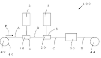
- FIG. 1 is a schematic diagram showing a manufacturing apparatus 100 for a long resin composite according to this embodiment.
- the apparatus 100 for producing a long resin composite continuously forms a long resin composite including a long base A and a resin portion formed on the base A. It is a device that manufactures automatically.
- the apparatus 100 for producing a long resin composite coats a catalyst solution on at least one surface of a transport mechanism 40 that transports a long base material A along its longitudinal direction P and the base material A that is being transported.
- a coating liquid (coating film) is formed by applying a monomer liquid containing a monomer to at least one surface of the base material B coated with the catalyst liquid and a catalyst liquid coating mechanism 10 as a catalyst supporting mechanism to be worked A monomer liquid coating mechanism 20 as a coating film forming step, and the coated material is heated to a predetermined temperature, and the monomer is polymerized by the action of the polymerization catalyst in the catalyst liquid to obtain a resin portion. And a heating mechanism 30 for forming the resin composite D.
- the catalyst supporting mechanism for applying the catalyst solution is used as the catalyst supporting mechanism.
- the present invention is not limited to this, and any mechanism capable of supporting the catalyst on the substrate may be used.
- the base material may be immersed in the catalyst solution. Furthermore, it is good also as a structure made to carry
- a coating film can be formed in a base material Any mechanism may be used.
- a structure in which a base material on which a catalyst is supported is immersed in a monomer solution to form a coating film may be employed.
- the elongated base material A examples include metal foil, synthetic resin film, fiber base material, and the like.
- a resin composite D having these substrates and a resin portion formed on the substrate surface is formed.
- a fiber base material since the coating liquid before polymerization (polymerizable composition, etc.) is impregnated not only in the fiber base surface but also inside, the fiber base material and the resin part And a prepreg as a resin composite D in the form of a resin sheet.
- the resin composite D can be made into what can form a coating film on the surface, or what can form an impregnation (prepreg), when a catalyst liquid and a monomer liquid are applied.
- the metal foil examples include a copper foil, an aluminum foil, a nickel foil, a chrome foil, a gold foil, and a silver foil.
- a copper foil is preferable.
- the copper foil is not particularly limited as long as it is used for a normal copper-clad laminate, and the thickness and roughened state can be appropriately selected according to the purpose of use.
- the surface of the metal foil may be treated with a silane coupling agent, a thiol coupling agent, a titanate coupling agent, various adhesives, or the like.
- Examples of the synthetic resin film include polyethylene terephthalate film, polypropylene film, polyethylene film, polycarbonate film, polyethylene naphthalate film, polyarylate film, nylon film, polytetrafluoroethylene film, and the like.
- the “long shape” means a band shape having a width direction and a length direction longer than the width direction dimension, preferably a length direction of 10 times or more.
- the length of the base material A (length in the longitudinal direction) is not particularly limited, but is usually 400 to 2000 m.
- the width dimension of the substrate A (the length in the width direction as a direction perpendicular to the longitudinal direction) is not particularly limited, but is usually 450 to 1300 mm, preferably 530 to 1280 mm.
- the thickness of the substrate A is not particularly limited, but is usually 5 to 100 ⁇ m, preferably 15 to 80 ⁇ m.
- the fiber base material is a base material for reinforcing the prepreg as a resin composite to be obtained, and a sheet such as a knitted fiber, a woven fabric, and a non-woven fabric. It is the member formed in the shape.
- the fiber used for the fiber base material include inorganic and / or organic fibers. Examples of these fibers include organic fibers such as PET (polyethylene terephthalate) fibers, aramid fibers, ultra-high molecular weight polyethylene fibers, polyamide (nylon) fibers, and liquid crystal polyester fibers; glass fibers, carbon fibers, alumina fibers, and tungsten fibers.
- inorganic fibers such as molybdenum fiber, titanium fiber, steel fiber, boron fiber, silicon carbide fiber, and silica fiber.
- organic fibers and glass fibers are preferable, and aramid fibers, liquid crystal polyester fibers, and glass fibers are particularly preferable.
- the glass fiber fibers such as E glass, NE glass, S glass, D glass, H glass, Q glass, and T glass can be suitably used. From the viewpoint of preventing local differences in the dielectric constant of the impregnation (prepreg) resulting from the density of the fiber bundle constituting the fiber, the dielectric constant of the layer made of the coating liquid and the dielectric constant of the material constituting the fiber substrate A smaller difference is preferable.
- the fiber may be used by opening a fiber bundle.
- Examples of the resin part constituting the resin composite include a polymerization reaction product of a polymerizable composition containing a monomer and a polymerization catalyst.
- a polymerization reaction product of a polymerizable composition containing a monomer and a polymerization catalyst As the polymerization method, solution polymerization and bulk polymerization can be adopted, but bulk polymerization is preferable.
- a cycloolefin monomer can be used as the monomer contained in the monomer liquid.
- the cycloolefin monomer is a compound having an alicyclic structure formed of carbon atoms and having a polymerizable carbon-carbon double bond in the alicyclic structure.
- polymerizable carbon-carbon double bond refers to a carbon-carbon double bond mainly involved in polymerization (metathesis ring-opening polymerization, addition polymerization, etc.).
- Examples of the alicyclic structure of the cycloolefin monomer include monocyclic, polycyclic, condensed polycyclic, bridged ring, and combination polycyclic thereof.
- a polycyclic cycloolefin monomer is preferable from the viewpoint of improving the mechanical strength of the molded body, for example, when a molded body such as a circuit board is molded using a prepreg as a resin composite.
- the number of carbon atoms constituting each ring structure is not particularly limited, but is usually 4 to 30, preferably 5 to 20, and more preferably 5 to 15.
- the cycloolefin monomer may have a hydrocarbon group having 1 to 30 carbon atoms such as an alkyl group, an alkenyl group, an alkylidene group, and an aryl group, or a polar group such as a carboxyl group or an acid anhydride group as a substituent. Good.
- crosslinkable carbon-carbon unsaturated bond means a carbon-carbon unsaturated bond that hardly participates in the polymerization and mainly participates in a crosslinking reaction.
- Crosslinking reaction refers to a reaction that forms a bridge structure.
- the “crosslinking reaction” usually means a radical crosslinking reaction or a metathesis crosslinking reaction, particularly a radical crosslinking reaction.
- Crosslinkable carbon-carbon unsaturated bonds include carbon-carbon unsaturated bonds other than aromatic carbon-carbon unsaturated bonds, that is, aliphatic carbon-carbon double bonds or triple bonds. -Refers to a carbon double bond.
- the position of the unsaturated bond is not particularly limited, and any position other than the alicyclic structure other than the alicyclic structure formed by carbon atoms. For example, at the end or inside of the side chain.
- the aliphatic carbon-carbon double bond may exist as a vinyl group (CH 2 ⁇ CH—), a vinylidene group (CH 2 ⁇ C ⁇ ), or a vinylene group (—CH ⁇ CH—), Since it exhibits radical crosslinkability, it preferably exists as a vinyl group and / or vinylidene group, and more preferably as a vinylidene group.
- a norbornene monomer having at least one crosslinkable carbon-carbon unsaturated bond is particularly preferable.
- the “norbornene monomer” refers to a cycloolefin monomer having a norbornene ring structure in the molecule.
- norbornenes, dicyclopentadiene, tetracyclododecenes and the like can be mentioned.
- cycloolefin monomer having at least one crosslinkable carbon-carbon unsaturated bond examples include 3-vinylcyclohexene, 4-vinylcyclohexene, 1,3-cyclopentadiene, 1,3-cyclohexadiene, 1,4- Monocyclic cycloolefin monomers such as cyclohexadiene, 5-ethyl-1,3-cyclohexadiene, 1,3-cycloheptadiene, 1,3-cyclooctadiene; 5-ethylidene-2-norbornene, 5-methylidene Norbornene monomers such as -2-norbornene, 5-isopropylidene-2-norbornene, 5-vinylnorbornene, 5-allylnorbornene, 5,6-diethylidene-2-norbornene, dicyclopentadiene, 2,5-norbornadiene; Can be mentioned.
- norbornene such as
- cycloolefin monomer in addition to the cycloolefin monomer having at least one crosslinkable carbon-carbon unsaturated bond, a cycloolefin monomer having no crosslinkable carbon-carbon unsaturated bond is used.
- cycloolefin monomers having no crosslinkable carbon-carbon unsaturated bond include cyclopentene, 3-methylcyclopentene, 4-methylcyclopentene, 3,4-dimethylcyclopentene, 3,5-dimethylcyclopentene, 3-chlorocyclopentene, Monocyclic cycloolefin monomers such as cyclohexene, 3-methylcyclohexene, 4-methylcyclohexene, 3,4-dimethylcyclohexene, 3-chlorocyclohexene, cycloheptene; norbornene, 5-methylnorbornene, 5-ethylnorbornene, 5-propylnorbornene, 5,6-dimethylnorbornene, 1-methylnorbornene, 7-methylnorbornene, 5,5,6-trimethylnorbornene, 5-phenylnorbornene, tetracyclododecene, 1, , 5,8-Dimethano-1
- the above cycloolefin monomers can be used alone or in combination of two or more.
- a mixture of a cycloolefin monomer having at least one crosslinkable carbon-carbon unsaturated bond and a cycloolefin monomer having no crosslinkable carbon-carbon unsaturated bond can be used.
- the polymerization catalyst is not particularly limited as long as it is a catalyst capable of polymerizing the monomer.
- the monomer is the cycloolefin monomer
- an addition polymerization catalyst or a ring-opening polymerization catalyst can be used.
- the cycloolefin monomer is polymerized in the presence of a cycloolefin monomer and another monomer copolymerizable with the cycloolefin monomer. You may make it obtain the copolymer containing this.
- an addition copolymer containing a cycloolefin monomer by addition polymerization in the presence of another monomer copolymerizable with the cycloolefin monomer Is an ⁇ -olefin having 2 to 20 carbon atoms such as ethylene, propylene, 1-butene, 1-pentene, 1-hexene, and derivatives thereof; 1,4-hexadiene, 4-methyl-1,4-hexadiene, Non-conjugated dienes such as 5-methyl-1,4-hexadiene and 1,7-octadiene; and the like.
- ⁇ -olefin is preferable, and ethylene is particularly preferable.
- addition polymerization catalyst for example, a known catalyst such as a catalyst comprising a titanium, zirconium or vanadium compound and an organoaluminum compound can be used.
- Any ring-opening polymerization catalyst may be used as long as it can cause ring-opening polymerization of a cycloolefin monomer.
- a metathesis polymerization catalyst can be used.
- the metathesis polymerization catalyst include a metal complex formed by bonding a plurality of ions, atoms, polyatomic ions and / or compounds with a transition metal atom as a central atom.
- transition metal atoms atoms of Group 5, Group 6, and Group 8 (long-period periodic table, the same shall apply hereinafter) are used.
- the atoms of each group are not particularly limited, and examples of the Group 5 atom include tantalum.
- Examples of the Group 6 atom include molybdenum and tungsten.
- Examples of the Group 8 atom include ruthenium and osmium. Is mentioned.
- a complex having a group 8 ruthenium or osmium as a central atom is preferable, and a ruthenium carbene complex is particularly preferable.
- ruthenium carbene complexes are relatively stable to oxygen and moisture in the air and are not easily deactivated, so that they can be used even in the atmosphere.
- These metathesis polymerization catalysts may be used alone or in combination of two or more.
- the blending amount of the metathesis polymerization catalyst can be the content described in, for example, JP-A-2009-242568.
- the metathesis polymerization catalyst can be used by dissolving or suspending in a small amount of an inert solvent, if desired.
- solvents include chain aliphatic hydrocarbons such as n-pentane, n-hexane, n-heptane, liquid paraffin, mineral spirits; cyclopentane, cyclohexane, methylcyclohexane, dimethylcyclohexane, trimethylcyclohexane, ethylcyclohexane, diethylcyclohexane , Cycloaliphatic hydrocarbons such as decahydronaphthalene, dicycloheptane, tricyclodecane, hexahydroindene, and cyclooctane; aromatic hydrocarbons such as indene, benzene, toluene, and xylene; nitrogen-containing compounds such as nitromethane, nitrobenzene, and acetonitrile Hydrocarbons
- the metathesis polymerization catalyst can be used in combination with an activator (cocatalyst) for the purpose of controlling the polymerization activity and improving the polymerization reaction rate.
- an activator cocatalyst
- aluminum, scandium, tin alkylated products, halides, alkoxylated products, aryloxylated products, and the like can be used.
- the use amount of the activator is usually 1: 0.05 to 1: 100, preferably 1: 0.2 to 1:20, more preferably 1 in terms of a molar ratio of (metal atom in the catalyst: activator). : The range is 0.5 to 1:10.
- both the metathesis polymerization catalyst and the activator are used by dissolving them in the monomer. As long as it is essentially not damaged, it can be suspended or dissolved in a solvent.
- the monomer liquid may optionally include a filler, a chain transfer agent, a crosslinking agent, a crosslinking aid, a flame retardant, a polymerization regulator, a polymerization reaction retarding agent, a reactive fluidizing agent, a flame retardant, You may mix
- the filler is not particularly limited, and for example, an organic substance or an inorganic substance can be used. From the viewpoint of obtaining the molded article having a higher elastic modulus, an inorganic substance is preferable.
- the shape of the filler is not particularly limited, and any shape such as a spherical shape, a granular shape, an indefinite shape, a dendritic shape, a needle shape, a rod shape, and a flat shape can be employed.
- the average particle diameter of the filler is not particularly limited, and is a median diameter containing 50% by volume of all particles measured by a laser scattering diffraction particle size distribution meter, and is usually 0.001 to 70 ⁇ m, preferably 0.00.
- the thickness is from 01 to 50 ⁇ m, more preferably from 0.05 to 15 ⁇ m, particularly preferably from 0.1 to 5 ⁇ m.
- the filler include calcium carbonate, magnesium carbonate, barium carbonate, zinc oxide, titanium oxide, magnesium oxide, magnesium silicate, calcium silicate, zirconium silicate, hydrated alumina, magnesium hydroxide, aluminum hydroxide, Examples thereof include barium sulfate, silica, talc, and clay.
- the content of the filler is usually 50 to 600 parts by weight, preferably 100 to 550 parts by weight, and more preferably 200 to 500 parts by weight with respect to 100 parts by weight of the monomer. If the content of the filler is within such a range, the dispersibility of the filler in the polymerizable composition is excellent, and the impregnation property to the fiber base material is good.
- the chain transfer agent is a compound that has a carbon-carbon double bond that can participate in the ring-opening polymerization reaction and can be bonded to the terminal of the polymer formed by the polymerization reaction of the cycloolefin monomer.
- the chain transfer agent may have a crosslinkable carbon-carbon double bond in addition to the carbon-carbon double bond.
- chain transfer agents examples include aliphatic olefins such as 1-hexene and 2-hexene; aromatic olefins such as styrene, divinylbenzene and stilbene; alicyclic olefins such as vinylcyclohexane; vinyl ethers such as ethyl vinyl ether; And vinyl ketones such as methyl vinyl ketone, 1,5-hexadien-3-one and 2-methyl-1,5-hexadien-3-one.
- the amount of the chain transfer agent used is usually 0.01 to 10 parts by weight, preferably 0.1 to 5 parts by weight, based on 100 parts by weight of the monomer.
- the polymerizable composition in which the polymerization catalyst and the monomer are mixed may contain a crosslinking agent from the viewpoint that the obtained molded body can be configured as a post-crosslinkable resin layer.
- a crosslinking agent from the viewpoint that the obtained molded body can be configured as a post-crosslinkable resin layer.
- “after-crosslinking is possible” means that the molded body can be formed into a crosslinked molded body by, for example, heating the molded body to advance a crosslinking reaction.
- a radical generator is usually preferably used.
- the crosslinking agent is not particularly limited, but usually a radical generator is preferably used.
- the radical generator include organic peroxides, diazo compounds, and nonpolar radical generators, and organic peroxides and nonpolar radical generators are preferable.
- Organic peroxides include hydroperoxides such as t-butyl hydroperoxide, p-menthane hydroperoxide, cumene hydroperoxide; dicumyl peroxide, t-butylcumyl peroxide, ⁇ , ⁇ ′-bis (t-butylperoxy) -M-isopropyl) benzene, di-t-butyl peroxide, 2,5-dimethyl-2,5-di (t-butylperoxy) -3-hexyne, 2,5-dimethyl-2,5-di (t- Dialkyl peroxides such as butylperoxy) hexane; diacyl peroxides such as dipropionyl peroxide and benzoyl peroxide; 2,2-di (t-butylperoxy) butane, 1,1-di (t-hexylperoxy) cyclohexane, 1, 1-di (t-butylperoxy)
- diazo compound examples include 4,4'-bisazidobenzal (4-methyl) cyclohexanone, 2,6-bis (4'-azidobenzal) cyclohexanone, and the like.
- Nonpolar radical generators include 2,3-dimethyl-2,3-diphenylbutane, 3,4-dimethyl-3,4-diphenylhexane, 1,1,2-triphenylethane, 1,1,1- And triphenyl-2-phenylethane.
- the 1-minute half-life temperature of the radical generator is not particularly limited, but is usually in the range of 150 to 300 ° C, preferably 180 to 250 ° C.
- the 1-minute half-life temperature is a temperature at which half of the radical generator decomposes in 1 minute.
- the 1-minute half-life temperature of the radical generator may be referred to, for example, a catalog or homepage of each radical generator manufacturer (for example, Nippon Oil & Fats Co., Ltd.).
- the amount of the crosslinking agent is usually 0.1 to 10 parts by weight, preferably 0.5 to 5 parts by weight with respect to 100 parts by weight of the monomer. If the amount of the crosslinking agent is in the above range, a cured product obtained by curing the molded body has a sufficient crosslinking density, and a circuit board having desired physical properties can be obtained efficiently, which is preferable.
- the crosslinking aid is preferably a compound having a crosslinkable carbon-carbon unsaturated bond that does not participate in the polymerization but can participate in the crosslinking reaction induced by the crosslinking agent.
- a crosslinkable carbon-carbon unsaturated bond is preferably present, for example, as a terminal vinylidene group, particularly as an isopropenyl group or (meth) acryl group, in the compound constituting the crosslinking aid. More preferably it exists as an acrylic group.
- the (meth) acryl group means that both a methacryl group and an acryl group are included.
- crosslinking aid examples include polyfunctional compounds having two or more isopropenyl groups such as p-diisopropenylbenzene, m-diisopropenylbenzene, o-diisopropenylbenzene; lauryl methacrylate, benzyl methacrylate, tetrahydro Monofunctional compounds having one methacryl group, such as furfuryl methacrylate and methoxydiethylene glycol methacrylate; Monofunctional compounds having one acrylic group, such as lauryl acrylate, benzyl acrylate, tetrahydrofurfuryl acrylate, and methoxydiethylene glycol acrylate; ethylene Dimethacrylate, 1,3-butylene dimethacrylate, 1,4-butylene dimethacrylate, 1,6-hexanediol dimethacrylate, polyethylene glycol Methacrylate, polyethylene glycol dimethacrylate, ethylene glycol dimethacrylate,
- the crosslinking assistants can be used alone or in combination of two or more.
- the blending amount of the crosslinking aid is usually 0.1 to 100 parts by weight, preferably 0.5 to 50 parts by weight, more preferably 1 to 30 parts by weight with respect to 100 parts by weight of the monomer.
- the flame retardant is not particularly limited, and may be a known flame retardant, such as halogen flame retardant, phosphorus-nitrogen flame retardant, phosphate ester flame retardant, nitrogen flame retardant, and inorganic flame retardant, It can be appropriately selected and used. What is necessary is just to adjust the compounding quantity suitably so that a desired effect may be acquired.
- an inert solvent may be used for the catalyst solution as necessary.
- the inert solvent include chain aliphatic hydrocarbons such as n-pentane, n-hexane, and n-heptane; cyclopentane, cyclohexane, methylcyclohexane, dimethylcyclohexane, trimethylcyclohexane, ethylcyclohexane, decahydronaphthalene, Alicyclic hydrocarbons such as bicycloheptane, tricyclodecane, hexahydroindene and cyclooctane; aromatic hydrocarbons such as indene, benzene, toluene and xylene; nitrogen-containing hydrocarbons such as nitromethane, nitrobenzene and acetonitrile; diethyl ether, Ethers such as tetrahydrofuran; and the like.
- the coating amount of the catalyst solution is usually 0.1 to 4.0 g, preferably 0.2 to 1.7 g per 1 m 2 of the base material, although it depends on production conditions.
- the viscosity of the catalyst solution is 1 to 100 [mPa ⁇ s], preferably 5 to 50 [mPa ⁇ s].
- the viscosity is a measurement result in a range of a shear rate of 100 to 1000 [1 / s].
- the viscosity of the monomer liquid is 20 to 1500 [mPa ⁇ s], preferably 30 to 1000 [mPa ⁇ s].
- the viscosity is a measurement result in a range of a shear rate of 100 to 1000 [1 / s].
- the temperature of the monomer liquid at the time of coating is 10 to 80 ° C., preferably 20 to 40 ° C.
- the transport mechanism 40 transports the long base material A at a predetermined transport speed, and winds up the long resin composite D as a processed base material that has been subjected to a coating process or the like on the surface. It is a device.
- the transport mechanism 40 includes a feed roll 42 that sequentially feeds the long base material A from the roll wound body of the base material A wound in a roll shape, and a long length that is fed from the feed roll 42 and processed.
- a take-up roll 44 that winds up the resin composite D and a transport unit (not shown) that appropriately adjusts the transport state of the substrate A.
- the delivery roll 42 and the take-up roll 44 are rolls that rotate at a predetermined speed.
- the said conveyance part is a part which controls the conveyance speed of the elongate base material A, adjusting the tension
- the conveying speed of the substrate A is 8 to 333 mm / second, preferably 17 to 167 mm / second.
- the catalyst solution coating mechanism 10 includes a catalyst solution tank 3 that stores the catalyst solution, and a catalyst solution application device 4 that continuously applies the catalyst solution in the catalyst solution tank 3 to the substrate A.
- the catalyst liquid tank 3 and the catalyst liquid coating device 4 are connected by piping. You may have the pump which adjusts the flow volume of a catalyst liquid in the middle of piping.
- the method for applying the catalyst solution in the catalyst solution coating apparatus 4 is not particularly limited.
- a coating method for example, a known coating method such as an inkjet coating method, a spray coating method, a dip coating method, a roll coating method, a curtain coating method, a die coating method, a slit coating method, or ultrasonic spraying may be used. Can do. Among these, since a small amount of catalyst solution can be applied more accurately, the inkjet coating method or the spray coating method is preferable, and the inkjet coating method is more preferable.
- a known coating apparatus such as those described in Japanese Patent Application Laid-Open No. 2007-234811 and Japanese Patent Application Laid-Open No. 2007-38141 can be used as the coating apparatus. it can.
- the catalyst solution coating apparatus 4 may be one that coats the catalyst solution on one side of the substrate A, or one that coats the catalyst solution on both sides of the substrate A. These can be appropriately selected according to the purpose. Moreover, you may provide a drying apparatus in the downstream of the catalyst liquid coating apparatus 4 as needed. By providing the drying device, the monomer liquid can be applied in the next step in a state in which there is almost no solvent remaining in the substrate A, so that the resin composite can be more stably produced.
- the drying conditions in this case can be 20 to 100 ° C. and 5 to 180 seconds.
- the monomer liquid coating mechanism 20 includes a monomer liquid tank 5 that stores the monomer liquid, and a monomer liquid coating apparatus 6 that continuously applies the monomer liquid in the monomer liquid tank 5 to the substrate A.
- the monomer liquid tank 5 and the monomer liquid coating device 6 are connected by piping. You may have the pump which adjusts the flow volume of a catalyst liquid in the middle of piping.
- the monomer liquid tank 5 has a temperature adjustment function capable of adjusting the temperature of the monomer liquid to a predetermined temperature. Since the continuous production apparatus of the resin composite of the present invention does not apply a polymerizable composition containing a catalyst solution and a monomer solution, the monomer solution is heated for the purpose of reducing the viscosity of the monomer solution. Even so, the monomer does not start to polymerize when the monomer liquid is applied. As described above, when the monomer liquid coating mechanism has a temperature adjusting function, the temperature of the monomer can be set to an arbitrary temperature and adjusted to a desired viscosity.
- the method of applying the monomer liquid using the monomer liquid coating apparatus 6 is not particularly limited.
- a known coating method such as an inkjet coating method, a spray coating method, a dip coating method, a roll coating method, a curtain coating method, a die coating method, a slit coating method, or ultrasonic spraying may be used. It can.
- the die coating method is preferable because the monomer liquid can be applied more accurately.
- a known coating apparatus such as those described in Japanese Patent Application Laid-Open No. 2001-170541 and Japanese Patent Application Laid-Open No. 2004-290771 can be used.
- the monomer liquid coating device 6 may be one that coats the monomer liquid on one side of the substrate A, or may coat the monomer liquid on both sides of the substrate A. These can be appropriately selected according to the purpose.
- This composite C is a composite of a base material and a coating film, and an embodiment as a composite in which a coated product is formed on the base material, and an impregnated product obtained by impregnating the base material with a polymerizable composition As an embodiment.
- a laminating apparatus may be provided on the downstream side of the monomer liquid coating apparatus 6 as necessary.
- the laminating apparatus is an apparatus having a pair of laminating rolls, and a laminated body is obtained by stacking a protective film on the front surface and / or the back surface of the composite C. A composite with a protective film having a thickness of 10 mm is produced.
- the catalyst liquid and the monomer liquid can be mixed more efficiently.
- the thickness of the composite C can be made constant, the resin composite D having a constant thickness can be produced efficiently.
- a film having releasability with the resin to be formed is preferable, for example, polyethylene terephthalate film, polypropylene film, polyethylene film, polycarbonate film, polyethylene naphthalate film, polyarylate film, nylon film, polytetrafluoroethylene film, etc. Is mentioned.
- the heating mechanism 30 is an apparatus that obtains a resin portion as a polymer by heating the composite C to a predetermined temperature and polymerizing the monomer by the action of a polymerization catalyst. That is, the long resin composite D is a resin composite including the base material A and the resin portion. Specific examples of the configuration of the heating mechanism 30 include a heating roll, a heating plate, and a heating furnace. According to these methods, a resin composite excellent in smoothness and thickness accuracy can be obtained continuously and efficiently.
- the heating temperature is usually 100 to 300 ° C, preferably 100 to 250 ° C, more preferably 110 to 200 ° C, and still more preferably 120 to 180 ° C.
- the heating time is 30 to 300 seconds, preferably 60 to 240 seconds, more preferably 90 to 210 seconds, depending on the heating temperature and the conveyance speed of the substrate A.
- the apparatus for producing a long resin composite according to the present invention coats a catalyst solution and a monomer solution without mixing them. Therefore, according to the present invention, even when a highly active polymerization catalyst or a highly reactive polymerizable monomer is used, these can be stably applied, and a resin composite having a uniform quality can be stabilized. And can be manufactured continuously and efficiently. Furthermore, according to the present invention, the viscosity can be freely controlled by appropriately adjusting the temperature of the monomer liquid. For this reason, according to the present invention, a wide variety of monomer liquids can be coated under more suitable coating conditions to form a target resin composite.
- FIG. 1 A method of continuously producing a long resin composite using the long resin composite production apparatus 100 will be described.
- a wound body in which a long base A is wound is prepared, and this wound body is attached to a delivery roll 42 of a transport device 40, and a catalyst solution coating mechanism 10, a monomer solution
- a delivery roll 42 of a transport device 40 is attached to a delivery roll 42 of a transport device 40, and a catalyst solution coating mechanism 10, a monomer solution
- Each device is arranged so as to pass through the coating mechanism 20 and the heating mechanism 30 in this order.
- the rotation speed and the like of the delivery roll 42 and the take-up roll 44 are adjusted by the transport unit, and the long base material A is transported along the longitudinal direction at a predetermined speed (transport process).
- the catalyst solution in the catalyst solution tank 3 is sent to the catalyst solution coating device 4 at a predetermined flow rate by a pump or the like, and the catalyst solution coating device 4 applies, for example, to the front and back surfaces of the substrate A being conveyed.
- a catalyst solution is applied by an ink jet method (catalyst supporting step).
- the catalyst solution is applied to the front and back surfaces of the substrate A.
- the catalyst solution may be applied to at least one surface of the substrate A.
- the temperature of the monomer liquid in the monomer liquid tank 5 is adjusted to a predetermined temperature by the temperature adjustment function to adjust the viscosity (temperature adjustment step), and the monomer liquid is applied to the monomer liquid at a predetermined flow rate by a pump or the like.
- the monomer liquid coating device 6 has a coating by coating the monomer liquid by, for example, a die coating method on the front and back surfaces of the substrate B being transported coated with the catalyst liquid.
- a composite C as a substrate is formed (coating film forming step).
- the monomer liquid is applied to both the front and back surfaces of the base material B.
- the monomer liquid may be applied only to at least one surface of the base material B.
- the obtained long composite C is heated by the heating mechanism 30, and the monomers in the coating material in the composite C are polymerized and semi-cured by the action of the polymerization catalyst to make the long composite
- the resin composite D is obtained (heating step).
- this long resin composite D is wound up by the winding roll 44, and the long resin composite D formed as a wound body is manufactured (winding process).
- “semi-cured” means that the monomer in the coated product is polymerized into a state of a thermoplastic resin and is cured only to such an extent that it can be further cured by heating.
- the uncured state is also included.
- the insulating polymer constituting the resin layer is partly dissolved in a solvent that can be dissolved, or the volume swelling ratio when the resin layer is immersed in the solvent for 24 hours. , 200% or more before immersion.
- the method for producing the resin composite of the present invention is such that the catalyst solution and the monomer solution are not mixed, but each is sequentially coated on one or both sides of the substrate. For this reason, according to the method for producing a resin composite of the present invention, even when a highly active polymerization catalyst or a highly reactive polymerizable monomer is used, these can be stably applied to achieve uniform quality. Can be produced stably and continuously. Moreover, the manufacturing method of the resin composite of this invention can control the viscosity freely, for example by adjusting the temperature of a monomer.
- the monomer liquid used has a high filler content and a high viscosity, it can be uniformly applied to the substrate in a state where only the monomer liquid is heated to a low viscosity. As a result, a resin composite having uniform quality can be produced stably and continuously.
- a wide variety of monomer liquids can be applied under more suitable coating conditions to form a target resin composite.
- the apparatus for producing a long resin composite according to the second embodiment of the present invention includes a transport mechanism that transports a long base material carrying a polymerization catalyst along the longitudinal direction, and the polymerization during transport.
- the method for producing the long resin composite according to the present invention includes a transporting step of transporting the long base material carrying the polymerization catalyst along a longitudinal direction, and the transporting step of the transporting step.
- a long base material A is preliminarily supported by a polymerization catalyst, and the base material supported by the polymerization catalyst is transported along the longitudinal direction.
- the catalyst liquid coating mechanism 10 and the monomer liquid coating mechanism 20 are installed on the substrate A and the coating process is continuously performed. That is, the polymerization catalyst is supported on the base material A in a process or apparatus different from the manufacturing apparatus 100. Also in the second embodiment, the same effect as in the first embodiment can be obtained.
- the manufacturing method of the elongate resin composite of this invention conveys the said elongate base material which carry
- the same effect as in the second embodiment can be obtained.
- the respective configurations of the coating film forming step (coating layer forming mechanism) and the catalyst supporting step (catalyst supporting mechanism) can be the same as those in the first embodiment.
- Example 1 The catalyst solution and the monomer solution obtained above were placed in the catalyst solution tank 3 and the monomer solution tank 5 of the long resin composite production apparatus 100 shown in FIG. 1, and each tank was cooled to 20 ° C.
- a small tube pump is connected to each of the catalyst liquid tank 3 and the monomer liquid tank 5, and the catalyst liquid coating mechanism 10 which is an ink jet coater and the monomer liquid coating mechanism which is a die coater at flow rates of 0.32 g / min and 60 g / min, respectively. 20 was fed.
- the catalyst solution coating is performed.
- the catalyst solution was applied to both surfaces of the substrate A by the mechanism 10, and the monomer solution was applied to both surfaces of the substrate by the monomer solution coating mechanism 20 to obtain a composite C.
- a protective film [a long polyethylene naphthalate film having a thickness of 25 ⁇ m and a width of 630 mm (Q51: manufactured by Teijin DuPont Films Ltd.)] is superimposed on the front and back surfaces of the composite C to obtain a laminate, and this laminate is obtained.
- the body was passed between a pair of metal rolls with a gap adjusted to 150 ⁇ m so that the coating thickness was 100 ⁇ m.
- the laminate was continuously sent to a heating furnace as a heating mechanism 30 maintained at 125 ⁇ 5 ° C.
- the composite C was heated in a heating furnace for 3 minutes, and the coated product corresponding to the polymerizable composition was bulk polymerized to obtain a resin composite D with a protective film.
- Catalyst liquid tank 4 Catalyst liquid coating apparatus 5: Monomer liquid tank 6: Monomer liquid coating apparatus 10: Catalyst liquid coating mechanism (catalyst carrying mechanism) 20: Monomer liquid coating mechanism (coating film formation mechanism) 30: Heating mechanism 40: Conveying mechanism 42: Delivery roll 44: Winding roll 100: Manufacturing apparatus for long resin composite A: Substrate B: Substrate C coated with catalyst solution C: Composite D: Resin Complex
Landscapes
- Chemical & Material Sciences (AREA)
- Engineering & Computer Science (AREA)
- Materials Engineering (AREA)
- Organic Chemistry (AREA)
- Chemical Kinetics & Catalysis (AREA)
- Manufacturing & Machinery (AREA)
- Health & Medical Sciences (AREA)
- Medicinal Chemistry (AREA)
- Polymers & Plastics (AREA)
- Inorganic Chemistry (AREA)
- Wood Science & Technology (AREA)
- Life Sciences & Earth Sciences (AREA)
- Polyoxymethylene Polymers And Polymers With Carbon-To-Carbon Bonds (AREA)
- Reinforced Plastic Materials (AREA)
- Laminated Bodies (AREA)
Abstract
本発明は、長尺状の基材と、前記基材上に形成された樹脂部分とを備える長尺状の樹脂複合体を連続的に製造する長尺状樹脂複合体の製造装置であって、所定の搬送機構、塗膜形成機構及び加熱機構を備える長尺状樹脂複合体の製造装置、並びに、長尺状の基材と、前記基材上に形成された樹脂部分とを備える長尺状の樹脂複合体を連続的に製造する長尺状樹脂複合体の製造方法であって、所定の搬送工程、塗膜形成工程及び加熱工程を備える長尺状樹脂複合体の製造方法である。本発明によれば、長尺状の樹脂複合体を効率よく製造できる長尺状樹脂複合体の製造装置、及び長尺状樹脂複合体の製造方法が提供される。
Description
本発明は、長尺状の樹脂複合体を効率よく製造できる長尺状樹脂複合体の製造装置、及び長尺状樹脂複合体の製造方法に関する。
従来、繊維基材に塗工液を含浸させた含浸物であるプリプレグ(樹脂複合体)は、回路基板の材料等として広く用いられている。長尺状のプリプレグは、たとえば予めモノマー及び重合触媒を混合した重合性組成物を長尺状の繊維基材に含浸させて長尺状の含浸物を得て、次いで、この含浸物を加熱等により重合して得ることができる。具体的には、たとえば特許文献1には、ガラスクロスを搬送しながら、両面ダイコータを用いて、前記重合性組成物をガラスクロスの表裏面に連続塗工して含浸物を得た後、所定のラミネート装置を用いて、この含浸物の両面に保護フィルムを重ね合わせて積層体を得て、次いで、この積層体を一対のロール間を通過させて厚みを一定にした後、厚み調整がなされた積層体を加熱して積層体中の重合性組成物を重合することにより、長尺状の保護フィルム付きプリプレグを製造する方法が開示されている。このように、特許文献1では、重合触媒とモノマー液を予め混合した重合性組成物を調製し、この重合性組成物を基材上に塗工して用いている。
しかしながら、たとえば、重合性組成物の粘度を下げる目的で、重合性組成物を加熱して塗工温度を上昇させる場合等において、重合性組成物の調製直後から重合反応が開始し、組成物の粘度が上昇し、プリプレグを安定して連続的に製造することが困難となることがあった。この問題は、基材が繊維基材であるプリプレグに限らず、繊維基材の代わりに他の基材を用いて樹脂複合体を形成する場合にも同様に生じていた。このため、長尺状樹脂複合体をより一層効率よく製造する技術の開発が望まれている。
本発明の目的は、長尺状樹脂複合体を効率よく製造できる長尺状樹脂複合体の製造装置、及び長尺状樹脂複合体の製造方法を提供することである。
本発明は、長尺状の基材と、前記基材上に形成された樹脂部分とを備える長尺状の樹脂複合体を連続的に製造する長尺状樹脂複合体の製造装置であって、重合触媒を担持した長尺状の基材を長手方向に沿って搬送する搬送機構と、搬送中の前記重合触媒を担持した長尺状の基材の少なくとも一方の面に、モノマーを含むモノマー液からなる塗膜を形成する塗膜形成機構と、前記塗膜を所定温度まで加熱して、前記重合触媒の作用により前記モノマーを重合させて前記樹脂部分を得る加熱機構と、を備える。
本発明によれば、基材に対して予め重合触媒を担持させた後、この触媒を担持した搬送中の基材に対して、塗膜形成機構がモノマー液を塗布して塗膜を得、この塗膜を加熱機構により加熱して重合する構成であるため、予め、触媒とモノマーとを混合した塗工液を基材に対して塗工する場合のように、誤って重合反応が開始してしまう可能性がほとんどないから、より一層効率的に長尺状の樹脂複合体を製造できる。また、重合触媒を担持させる機構を、モノマー液からなる塗膜を形成する機構から分離しているため、仮に触媒を担持させる工程でトラブルが生じた場合であっても、後工程である塗膜形成の工程に影響を及ぼすことがなく、効率的に樹脂複合体を製造できる。
また、本発明は、長尺状の基材と、前記基材上に形成された樹脂部分とを備える長尺状の樹脂複合体を連続的に製造する長尺状樹脂複合体の製造装置であって、前記長尺状の基材を長手方向に沿って搬送する搬送機構と、搬送中の前記長尺状の基材に重合触媒を担持させる触媒担持機構と、前記触媒が担持された長尺状の基材の少なくとも一方の面に、モノマーを含むモノマー液からなる塗膜を形成する塗膜形成機構と、前記塗膜を所定温度まで加熱して、前記重合触媒の作用により前記モノマーを重合させて前記樹脂部分を得る加熱機構と、を備える。
本発明によれば、搬送中の長尺状の基材に対して重合触媒を触媒担持機構が担持させ、その後、触媒が担持された基材に対して、塗膜形成機構がモノマー液からなる塗膜を得、この塗膜を加熱機構により加熱して重合する構成であるため、予め、触媒とモノマーとを混合した塗工液を基材に対して塗工する場合のように、誤って重合反応が開始してしまう可能性がほとんどないため、長尺状の樹脂複合体をより一層効率的に製造できる。また、基材の搬送経路上に、触媒担持機構と塗膜形成機構とを配置し、搬送中の基材に対してこれらの処理を連続的に行う比較的簡単な構成を採用するだけで、長尺状の樹脂複合体を簡便に製造できる。
ここで、前記触媒担持機構は、前記基材の少なくとも一方の面に前記触媒液を塗工することが好ましい。このような構成によれば、基材に対して触媒を比較的簡単に担持できる。
前記触媒担持機構は、前記基材の少なくとも一方の面に前記重合触媒を含む触媒液をインクジェットコート法により塗工することが好ましい。このような構成によれば、基材に対して触媒液を均一に塗工するため、モノマー液中のモノマーと均一に接触して、重合を確実に行うことができる。しがたって、より一層高品質な長尺状の樹脂複合体を製造できる。
ここで、前記塗膜形成機構は、前記触媒が担持された長尺状の基材の少なくとも一方の面に、前記モノマー液を塗工して前記塗膜を形成することが好ましい。このような構成によれば、基材に対してモノマー液を比較的簡単に塗工できる。
前記塗膜形成機構は、前記モノマー液の塗工温度を所定温度に調節する温度調節機能を有することが好ましい。従来のように、重合触媒とモノマー液を含む塗工液を加熱すると誤って重合反応が開始する場合があるが、本構成によれば、基材に対して触媒とモノマーとを別々に塗工するため、温度調節機能によりモノマー液を加熱しても誤った重合反応が開始することなく粘度を下げることができる。このようにモノマー液の粘度を下げることができるから、モノマー液を基材に対して均一に、かつより一層効率的に塗工でき、膜厚が安定した高品質な長尺状の樹脂複合体を効率的に製造できる。
本発明は、長尺状の基材と、前記基材上に形成された樹脂部分とを備える長尺状の樹脂複合体を連続的に製造する長尺状樹脂複合体の製造方法であって、重合触媒を担持した前記長尺状の基材を長手方向に沿って搬送する搬送工程と、前記搬送工程により搬送される前記重合触媒を担持した長尺状の基材の少なくとも一方の面に、モノマーを含むモノマー液からなる塗膜を形成する塗膜形成工程と、前記塗膜を所定温度まで加熱して、前記重合触媒の作用により前記モノマーを重合させて前記樹脂部分を得る加熱工程と、を備える。
本発明によれば、予め重合触媒を担持した搬送中の基材に対してモノマー液からなる塗膜を形成し(搬送工程、塗膜形成工程)、この塗膜を加熱して重合する(加熱工程)構成であるため、予め、触媒とモノマーとを混合した塗工液を基材に対して塗工する場合のように、誤って重合反応が開始してしまう可能性がほとんどないから、より一層効率的に長尺状樹脂複合体を製造できる。
また、本発明は、長尺状の基材と、前記基材上に形成された樹脂部分とを備える長尺状の樹脂複合体を連続的に製造する長尺状樹脂複合体の製造方法であって、前記長尺状の基材を長手方向に沿って搬送する搬送工程と、前記搬送工程により搬送される前記長尺状の基材に重合触媒を担持させる触媒担持工程と、前記触媒が担持された長尺状の基材の少なくとも一方の面に、モノマーを含むモノマー液からなる塗膜を形成する塗膜形成工程と、前記塗膜を所定温度まで加熱して、前記重合触媒の作用により前記モノマーを重合させて前記樹脂部分を得る加熱工程と、を備える。
本発明によれば、搬送中の長尺状の基材に対して重合触媒を担持させ(触媒担持工程)、その後、触媒が担持された基材に対してモノマー液からなる塗膜を形成し(塗膜形成工程)、この塗膜を加熱して重合する(加熱工程)構成であるため、予め、触媒とモノマーとを混合した塗工液を基材に対して塗工する場合のように、誤って重合反応が開始してしまう可能性がほとんどないから、長尺状樹脂複合体をより一層効率的に製造できる。また、基材の搬送経路上に、触媒担持工程と塗膜形成工程を設け、搬送中の基材に対してこれらの処理を連続的に行う比較的簡単な構成を採用するだけで、長尺状樹脂複合体を簡便に製造できる。
ここで、前記触媒担持工程は、前記基材の少なくとも一方の面に前記重合触媒を含む触媒液を塗工することが好ましい。また、前記塗膜形成工程は、前記触媒が担持された長尺状の基材の少なくとも一方の面に、前記モノマー液を塗工して前記塗膜を形成することが好ましい。このような構成によれば、基材に対してモノマー液または触媒液を比較的簡単に塗工できる。
前記塗膜形成工程は、前記モノマー液の塗工温度を5~80℃に調節する温度調節ステップと、温度調節されたモノマー液を前記基材に塗工して塗膜を形成する塗膜形成ステップと、を備えることが好ましい。このような構成によれば、基材に対して触媒とモノマーとを別々に設けるため、温度調節ステップによりモノマー液を加熱しても誤った重合反応が開始することなく粘度を下げることができる。このようにモノマー液の粘度を下げることができるから、モノマー液を基材に対して均一に、かつより一層効率的に塗工でき、膜厚が安定した品質のよい長尺状樹脂複合体を効率的に製造できる。
本発明の長尺状樹脂複合体の製造装置及び長尺状樹脂複合体の製造方法によれば、長尺状の樹脂複合体をより一層効率的に製造できる。
以下、本発明の一実施形態に係る長尺状樹脂複合体の製造装置について、図面を参照して説明する。ただし、本発明は、本実施形態には限定されない。
本実施形態に係る長尺状樹脂複合体の製造装置100を示す模式図を図1に示す。
図1に示すように、長尺状樹脂複合体の製造装置100は、長尺状の基材Aと、基材A上に形成された樹脂部分とを含む長尺状の樹脂複合体を連続的に製造する装置である。長尺状樹脂複合体の製造装置100は、長尺状の基材Aをその長手方向Pに沿って搬送する搬送機構40と、搬送中の基材Aの少なくとも一方の面に触媒液を塗工する触媒担持機構としての触媒液塗工機構10と、触媒液が塗工された基材Bの少なくとも一方の面にモノマーを含むモノマー液を塗工して塗工物(塗膜)を形成する塗膜形成工程としてのモノマー液塗工機構20と、塗工物を所定温度まで加熱して前記触媒液中の重合触媒の作用により前記モノマーを重合させて樹脂部分を得て、長尺状の樹脂複合体Dを形成する加熱機構30と、を備える。
図1に示すように、長尺状樹脂複合体の製造装置100は、長尺状の基材Aと、基材A上に形成された樹脂部分とを含む長尺状の樹脂複合体を連続的に製造する装置である。長尺状樹脂複合体の製造装置100は、長尺状の基材Aをその長手方向Pに沿って搬送する搬送機構40と、搬送中の基材Aの少なくとも一方の面に触媒液を塗工する触媒担持機構としての触媒液塗工機構10と、触媒液が塗工された基材Bの少なくとも一方の面にモノマーを含むモノマー液を塗工して塗工物(塗膜)を形成する塗膜形成工程としてのモノマー液塗工機構20と、塗工物を所定温度まで加熱して前記触媒液中の重合触媒の作用により前記モノマーを重合させて樹脂部分を得て、長尺状の樹脂複合体Dを形成する加熱機構30と、を備える。
なお、本実施形態では、触媒担持機構として、触媒液を塗工する触媒液担持機構を用いたが、これには限定されず、基材に対して触媒を担持できる機構であればよく、たとえば、触媒液中に基材を浸漬させる構成としてもよい。さらに、触媒液とせずに、固形状の触媒を用いて基材に担持させる構成としてもよい。
また、本実施形態では、塗膜形成機構として、モノマー液を塗工して塗膜を形成するモノマー液塗工機構を用いたが、これには限定されず、基材に塗膜を形成できる機構であればよく、たとえば、触媒が担持された基材をモノマー液を浸漬させて塗膜を形成する構成としてもよい。
長尺状の基材Aとしては、金属箔、合成樹脂製フィルム、繊維基材等を挙げることができる。基材Aとして、金属箔や合成樹脂製フィルムを用いた場合、これらの基材と該基材表面に形成された樹脂部分とを有する樹脂複合体Dが形成される。また、基材Aとして、繊維基材を用いた場合、重合前の塗工液(重合性組成物等)が繊維基材表面のみならず内部にも含浸されるため、繊維基材と樹脂部分とが一体となった樹脂シート状の樹脂複合体Dとしてのプリプレグが形成される。なお、樹脂複合体Dは、触媒液やモノマー液を塗工した際に、その表面に塗膜を形成し得るもの、または含浸物を形成し得るもの(プリプレグ)とすることができる。
金属箔としては、銅箔、アルミ箔、ニッケル箔、クロム箔、金箔、銀箔等を挙げることができ、この中でも銅箔が好ましい。銅箔としては、通常の銅張積層板に使用されるものであれば特に限定されず、その厚みや粗化状態は使用目的に応じて適宜選定できる。また金属箔は、その表面がシランカップリング剤、チオール系カップリング剤、チタネート系カップリング剤、各種接着剤等で処理されていてもよい。
合成樹脂製フィルムとしては、ポリエチレンテレフタレートフィルム、ポリプロピレンフィルム、ポリエチレンフィルム、ポリカーボネートフィルム、ポリエチレンナフタレートフィルム、ポリアリレートフィルム、ナイロンフィルム、ポリテトラフルオロエチレンフィルム等を挙げることができる。
ここで、「長尺状」とは、幅方向、及びこの幅方向の寸法に比べて長い寸法、好ましくは10倍以上の寸法の長手方向を有する帯状のことである。基材Aの長さ(長手方向の長さ)は、特に限定されないが、通常、400~2000mである。基材Aの幅寸法(前記長手方向に直交する方向としての幅方向の長さ)は、特に限定されないが、通常、450~1300mm、好ましくは530~1280mmである。基材Aの厚みは、特に限定されないが、通常、5~100μm、好ましくは15~80μmである。
長尺状の基材Aが繊維基材である場合、繊維基材は、得られる樹脂複合体としてのプリプレグを補強するための基材であり、繊維の編物、織布、及び不織布等のシート状に形成された部材である。繊維基材に用いる繊維としては、無機系及び/又は有機系の繊維を挙げることができる。これらの繊維としては、例えば、PET(ポリエチレンテレフタレート)繊維、アラミド繊維、超高分子ポリエチレン繊維、ポリアミド(ナイロン)繊維、及び液晶ポリエステル繊維等の有機繊維;ガラス繊維、炭素繊維、アルミナ繊維、タングステン繊維、モリブデン繊維、チタン繊維、スチール繊維、ボロン繊維、シリコンカーバイド繊維、及びシリカ繊維等の無機繊維;等を挙げることができる。
これらの中でも、有機繊維やガラス繊維が好ましく、特にアラミド繊維、液晶ポリエステル繊維、及びガラス繊維が好ましい。
ガラス繊維としては、Eガラス、NEガラス、Sガラス、Dガラス、Hガラス、Qガラス及びTガラス等の繊維を好適に用いることができる。
繊維を構成する繊維束の粗密から生じる含浸物(プリプレグ)の誘電率の局所的な差異を防ぐ観点から、塗工液からなる層の誘電率と繊維基材を構成する材料の誘電率との差は小さい方が好ましい。また、前記繊維は、繊維束を開繊して用いてもよい。
これらの中でも、有機繊維やガラス繊維が好ましく、特にアラミド繊維、液晶ポリエステル繊維、及びガラス繊維が好ましい。
ガラス繊維としては、Eガラス、NEガラス、Sガラス、Dガラス、Hガラス、Qガラス及びTガラス等の繊維を好適に用いることができる。
繊維を構成する繊維束の粗密から生じる含浸物(プリプレグ)の誘電率の局所的な差異を防ぐ観点から、塗工液からなる層の誘電率と繊維基材を構成する材料の誘電率との差は小さい方が好ましい。また、前記繊維は、繊維束を開繊して用いてもよい。
樹脂複合体を構成する樹脂部分には、モノマー及び重合触媒を含有する重合性組成物の重合反応生成物を挙げることができる。重合方法としては、溶液重合及び塊状重合を採用できるが、塊状重合が好ましい。
前記モノマー液に含まれるモノマーとしては、各種のモノマーを用いることができるが、たとえばシクロオレフィンモノマーを用いることができる。シクロオレフィンモノマーとは、炭素原子で形成される脂環構造を有し、かつ該脂環構造中に重合性の炭素-炭素二重結合を有する化合物である。本明細書において「重合性の炭素-炭素二重結合」とは、重合(メタセシス開環重合、付加重合等)に主として関与する炭素-炭素二重結合をいう。
シクロオレフィンモノマーの脂環構造としては、単環、多環、縮合多環、橋かけ環及びこれらの組み合わせ多環等を挙げることができる。シクロオレフィンモノマーとしては、樹脂複合体としてのプリプレグを用いて例えば回路基板等の成形体を成形した際に、この成形体の機械的強度を向上させる観点から、多環のシクロオレフィンモノマーが好ましい。各環構造を構成する炭素原子数に特に限定はないが、通常、4~30個、好ましくは5~20個、より好ましくは5~15個である。シクロオレフィンモノマーは、アルキル基、アルケニル基、アルキリデン基、及びアリール基等の炭素数1~30の炭化水素基や、カルボキシル基や酸無水物基等の極性基を置換基として有していてもよい。
前記シクロオレフィンモノマーには、前記成形体の機械的強度を向上させる観点から、架橋性炭素-炭素不飽和結合を少なくとも1つ有するものが好適に用いられる。本明細書において「架橋性炭素-炭素不飽和結合」とは、前記重合にはほとんど関与せず、主として架橋反応に関与する炭素-炭素不飽和結合をいう。「架橋反応」とは橋架け構造を形成する反応をいう。また、「架橋反応」とは、通常、ラジカル架橋反応又はメタセシス架橋反応、特にラジカル架橋反応をいう。
架橋性炭素-炭素不飽和結合としては、芳香族炭素-炭素不飽和結合を除く炭素-炭素不飽和結合、すなわち、脂肪族炭素-炭素二重結合又は三重結合が挙げられ、通常、脂肪族炭素-炭素二重結合をいう。架橋性炭素-炭素不飽和結合を有するシクロオレフィンモノマー中、該不飽和結合の位置は特に限定されるものではなく、炭素原子で形成される脂環構造内の他、該脂環構造以外の任意の位置、例えば、側鎖の末端や内部に存在していてもよい。例えば、前記脂肪族炭素-炭素二重結合は、ビニル基(CH2=CH-)、ビニリデン基(CH2=C<)、又はビニレン基(-CH=CH-)として存在し得、良好にラジカル架橋性を発揮することから、ビニル基及び/又はビニリデン基として存在するのが好ましく、ビニリデン基として存在するのがより好ましい。
架橋性炭素-炭素不飽和結合を少なくとも1つ有するシクロオレフィンモノマーとしては、特に、架橋性炭素-炭素不飽和結合を少なくとも1つ有するノルボルネン系モノマーが好ましい。「ノルボルネン系モノマー」とは、ノルボルネン環構造を分子内に有するシクロオレフィンモノマーをいう。例えば、ノルボルネン類、ジシクロペンタジエン類、及びテトラシクロドデセン類等が挙げられる。
架橋性炭素-炭素不飽和結合を少なくとも1つ有するシクロオレフィンモノマーとしては、例えば、3-ビニルシクロヘキセン、4-ビニルシクロヘキセン、1,3-シクロペンタジエン、1,3-シクロへキサジエン、1,4-シクロへキサジエン、5-エチル-1,3-シクロへキサジエン、1,3-シクロへプタジエン、1,3-シクロオクタジエン等の単環シクロオレフィンモノマー;5-エチリデン-2-ノルボルネン、5-メチリデン-2-ノルボルネン、5-イソプロピリデン-2-ノルボルネン、5-ビニルノルボルネン、5-アリルノルボルネン、5,6-ジエチリデン-2-ノルボルネン、ジシクロペンタジエン、2,5-ノルボルナジエン等のノルボルネン系モノマー;を挙げることができる。これらの中では、架橋性炭素-炭素不飽和結合を少なくとも1つ有するノルボルネン系モノマーが好ましい。
前記シクロオレフィンモノマーとしては、前記架橋性炭素-炭素不飽和結合を少なくとも1つ有するシクロオレフィンモノマーの他、架橋性炭素-炭素不飽和結合を持たないシクロオレフィンモノマーが用いられる。
架橋性炭素-炭素不飽和結合を持たないシクロオレフィンモノマーとしては、例えば、シクロペンテン、3-メチルシクロペンテン、4-メチルシクロペンテン、3,4-ジメチルシクロペンテン、3,5-ジメチルシクロペンテン、3-クロロシクロペンテン、シクロへキセン、3-メチルシクロへキセン、4-メチルシクロヘキセン、3,4-ジメチルシクロヘキセン、3-クロロシクロヘキセン、シクロへプテン等の単環シクロオレフィンモノマー;ノルボルネン、5-メチルノルボルネン、5-エチルノルボルネン、5-プロピルノルボルネン、5,6-ジメチルノルボルネン、1-メチルノルボルネン、7-メチルノルボルネン、5,5,6-トリメチルノルボルネン、5-フェニルノルボルネン、テトラシクロドデセン、1,4,5,8-ジメタノ-1,2,3,4,4a,5,8,8a-オクタヒドロナフタレン、2-メチル-1,4,5,8-ジメタノ-1,2,3,4,4a,5,8,8a-オクタヒドロナフタレン、2-エチル-1,4,5,8-ジメタノ-1,2,3,4,4a,5,8,8a-オクタヒドロナフタレン、2,3-ジメチル-1,4,5,8-ジメタノ-1,2,3,4,4a,5,8,8a-オクタヒドロナフタレン、2-ヘキシル-1,4,5,8-ジメタノ-1,2,3,4,4a,5,8,8a-オクタヒドロナフタレン、2-エチリデン-1,4,5,8-ジメタノ-1,2,3,4,4a,5,8,8a-オクタヒドロナフタレン、2-フルオロ-1,4,5,8-ジメタノ-1,2,3,4,4a,5,8,8a-オクタヒドロナフタレン、1,5-ジメチル-1,4,5,8-ジメタノ-1,2,3,4,4a,5,8,8a-オクタヒドロナフタレン、2-シクロへキシル-1,4,5,8-ジメタノ-1,2,3,4,4a,5,8,8a-オクタヒドロナフタレン、2,3-ジクロロ-1,4,5,8-ジメタノ-1,2,3,4,4a,5,8,8a-オクタヒドロナフタレン、2-イソブチル-1,4,5,8-ジメタノ-1,2,3,4,4a,5,8,8a-オクタヒドロナフタレン、1,2-ジヒドロジシクロペンタジエン、5-クロロノルボルネン、5,5-ジクロロノルボルネン、5-フルオロノルボルネン、5,5,6-トリフルオロ-6-トリフルオロメチルノルボルネン、5-クロロメチルノルボルネン、5-メトキシノルボルネン、5,6-ジカルボキシルノルボルネンアンハイドレート、5-ジメチルアミノノルボルネン、5-シアノノルボルネン等のノルボルネン系モノマー;を挙げることができる。これらの中でも、架橋性炭素-炭素不飽和結合を持たないノルボルネン系モノマーが好ましい。
以上のシクロオレフィンモノマーは、それぞれ単独で、あるいは2種以上を組み合わせて用いることができる。シクロオレフィンモノマーとしては、たとえば、架橋性炭素-炭素不飽和結合を少なくとも1つ有するシクロオレフィンモノマーと架橋性炭素-炭素不飽和結合を持たないシクロオレフィンモノマーとの混合物を用いることができる。
前記重合触媒としては、前記モノマーを重合可能な触媒であれば特に限定されず、たとえば、モノマーが前記シクロオレフィンモノマーである場合には、付加重合触媒や開環重合触媒を用いることができる。
前記重合触媒を用いて前記シクロオレフィンモノマーを重合して重合体を製造するにあたり、シクロオレフィンモノマーと、このシクロオレフィンモノマーと共重合可能な他のモノマーとの存在下で重合して、シクロオレフィンモノマーを含む共重合体を得るようにしてもよい。
シクロオレフィンモノマーと共重合可能な他のモノマーとの存在下で付加重合して、シクロオレフィンモノマーを含む付加共重合体を得る場合において、前記シクロオレフィンモノマーと共重合可能なその他の単量体としては、エチレン、プロピレン、1-ブテン、1-ペンテン、1-ヘキセン等の炭素数2~20のα-オレフィン、及びこれらの誘導体;1,4-ヘキサジエン、4-メチル-1,4-ヘキサジエン、5-メチル-1,4-ヘキサジエン、1,7-オクタジエン等の非共役ジエン;等が挙げられる。これらの中でも、α-オレフィンが好ましく、エチレンが特に好ましい。
付加重合触媒としては、例えば、チタン、ジルコニウム又はバナジウム化合物と有機アルミニウム化合物とからなる触媒等公知の触媒を用いることができる。
開環重合触媒としては、シクロオレフィンモノマーを開環重合させ得るものであればよく、たとえばメタセシス重合触媒を用いることができる。メタセシス重合触媒としては、遷移金属原子を中心原子として、複数のイオン、原子、多原子イオン及び/又は化合物が結合してなる金属錯体が挙げられる。遷移金属原子としては、5族、6族及び8族(長周期型周期表、以下同じ。)の原子が使用される。それぞれの族の原子は特に限定されないが、5族の原子としては、例えばタンタルが挙げられ、6族の原子としては、例えばモリブデン及びタングステンが挙げられ、8族の原子としては、例えばルテニウム及びオスミウムが挙げられる。
これらの中でも、メタセシス重合触媒としては、8族のルテニウムやオスミウムを中心原子とする錯体が好ましく、ルテニウムカルベン錯体が特に好ましい。ルテニウムカルベン錯体は、ルテニウム原子にカルベン炭素が二重結合した構造(Ru=C)を有する錯体であり、重合時の触媒活性が優れる。このため、メタセシス重合触媒としてルテニウムカルベン錯体を含む重合性組成物を重合して架橋性樹脂成形体を製造する場合、得られる架橋性樹脂成形体には未反応のモノマーに由来する臭気が少ない。したがって、生産性良く良質な成形体が得られる。また、ルテニウムカルベン錯体は、酸素や空気中の水分に対して比較的安定であって、失活しにくいので、大気下でも使用可能である。これらのメタセシス重合触媒は、それぞれ単独で、或いは、2種以上を組み合わせて用いてもよい。なお、メタセシス重合触媒の配合量等は、例えば特開2009-242568号公報に記載の内容とすることができる。
メタセシス重合触媒は所望により、少量の不活性溶剤に溶解又は懸濁して使用することができる。かかる溶剤としては、n-ペンタン、n-ヘキサン、n-ヘプタン、流動パラフィン、ミネラルスピリット等の鎖状脂肪族炭化水素;シクロペンタン、シクロヘキサン、メチルシクロヘキサン、ジメチルシクロヘキサン、トリメチルシクロヘキサン、エチルシクロヘキサン、ジエチルシクロヘキサン、デカヒドロナフタレン、ジシクロヘプタン、トリシクロデカン、ヘキサヒドロインデン、シクロオクタン等の脂環式炭化水素;インデン、ベンゼン、トルエン、キシレン等の芳香族炭化水素;ニトロメタン、ニトロベンゼン、アセトニトリル等の含窒素炭化水素;ジエチルエーテル、テトラヒドロフラン等の含酸素炭化水素;等が挙げられる。これらの中では、工業的に汎用な芳香族炭化水素や脂肪族炭化水素、脂環式炭化水素の使用が好ましい。また、メタセシス重合触媒としての活性を低下させないものであれば、液状の老化防止剤、液状の可塑剤、液状のエラストマーを溶剤として用いてもよい。
メタセシス重合触媒は、重合活性を制御し、重合反応率を向上させる目的で活性剤(共触媒)と併用することもできる。活性剤としては、アルミニウム、スカンジウム、スズの、アルキル化物、ハロゲン化物、アルコキシ化物及びアリールオキシ化物等を用いることができる。その具体例としては、トリアルコキシアルミニウム、トリフェノキシアルミニウム、ジアルコキシアルキルアルミニウム、アルコキシジアルキルアルミニウム、トリアルキルアルミニウム、ジアルコキシアルミニウムクロリド、アルコキシアルキルアルミニウムクロリド、ジアルキルアルミニウムクロリド、トリアルコキシスカンジウム、テトラアルコキシチタン、テトラアルコキシスズ、テトラアルコキシジルコニウム等が挙げられる。活性剤の使用量は、(触媒中の金属原子:活性剤)のモル比で、通常、1:0.05~1:100、好ましくは1:0.2~1:20、より好ましくは1:0.5~1:10の範囲である。
また、メタセシス重合触媒として、5族及び6族の遷移金属原子の錯体を用いる場合には、メタセシス重合触媒及び活性剤は、いずれもモノマーに溶解して用いるのが好ましいが、生成物の性質を本質的に損なわない範囲であれば、溶剤に懸濁又は溶解させて用いることができる。
前記モノマー液には、前記モノマーに加えて、所望により、充填剤、連鎖移動剤、架橋剤、架橋助剤、難燃剤、重合調整剤、重合反応遅延剤、反応性流動化剤、難燃剤、酸化防止剤、及び着色料等の配合剤を配合してもよい。また、前記触媒液には、前記重合触媒に加えて、所望により、前述と同様の配合剤を配合してもよい。
なお、モノマーとしてシクロオレフィンモノマーを用いた例を挙げて説明したが、これには限定されず、シクロオレフィンモノマー以外の他のモノマーを主として用いる場合もシクロオレフィンモノマーの場合と同様に扱うことができる。
前記充填剤は、特に限定されず、たとえば、有機物や無機物を用いることができるが、より高弾性率の前記成形体を得る観点から、無機物であることが好ましい。充填剤の形状は、特に限定されず、たとえば、球状、粒状、不定形状、樹枝状、針状、棒状、及び扁平状等の任意の形状を採用できる。また、充填剤の平均粒子径は、特に限定されず、レーザー散乱回折式粒度分布計で測定した全粒子の50体積%が含まれるメディアン径で、通常、0.001~70μm、好ましくは0.01~50μm、より好ましくは0.05~15μm、特に好ましくは、0.1~5μmである。
充填剤の具体例としては、炭酸カルシウム、炭酸マグネシウム、炭酸バリウム、酸化亜鉛、酸化チタン、酸化マグネシウム、ケイ酸マグネシウム、ケイ酸カルシウム、ケイ酸ジルコニウム、水和アルミナ、水酸化マグネシウム、水酸化アルミニウム、硫酸バリウム、シリカ、タルク、クレー等が挙げることができる。
充填剤の含有量は、たとえば前記モノマー100重量部に対して、通常、50~600重量部、好ましくは100~550重量部、より好ましくは200~500重量部である。充填剤の含有量がかかる範囲にあれば、前記重合性組成物中における充填剤の分散性が優れ、繊維基材への含浸性が良好となる。
連鎖移動剤は、開環重合反応に関与し得る炭素-炭素二重結合を有し、シクロオレフィンモノマーの重合反応で生成する重合体の末端に結合し得る化合物である。連鎖移動剤を用いることで、得られる樹脂の分子量を調製することができる。連鎖移動剤は、前記の炭素-炭素二重結合に加えて、架橋性の炭素-炭素二重結合を有していてもよい。
連鎖移動剤としては、1-ヘキセン、2-ヘキセン等の脂肪族オレフィン類;スチレン、ジビニルベンゼン、スチルベン等の芳香族オレフィン類;ビニルシクロヘキサン等の脂環式オレフィン類;エチルビニルエーテル等のビニルエーテル類;メチルビニルケトン、1,5-ヘキサジエン-3-オン、2-メチル-1,5-ヘキサジエン-3-オン等のビニルケトン類等が挙げられる。
連鎖移動剤の使用量としては、モノマー100重量部に対して、通常、0.01~10重量部、好ましくは0.1~5重量部である。
連鎖移動剤としては、1-ヘキセン、2-ヘキセン等の脂肪族オレフィン類;スチレン、ジビニルベンゼン、スチルベン等の芳香族オレフィン類;ビニルシクロヘキサン等の脂環式オレフィン類;エチルビニルエーテル等のビニルエーテル類;メチルビニルケトン、1,5-ヘキサジエン-3-オン、2-メチル-1,5-ヘキサジエン-3-オン等のビニルケトン類等が挙げられる。
連鎖移動剤の使用量としては、モノマー100重量部に対して、通常、0.01~10重量部、好ましくは0.1~5重量部である。
また、重合触媒とモノマーとを混合した重合性組成物は、得られる成形体を後架橋可能な樹脂層として構成し得るとする観点から、架橋剤を含有してもよい。ここで「後架橋可能な」とは、前記成形体を加熱する等して架橋反応を進行させて架橋成形体になし得ることを意味する。架橋剤としては、通常、ラジカル発生剤が好適に用いられる。
架橋剤としては、特に限定されないが、通常、ラジカル発生剤が好適に用いられる。ラジカル発生剤としては、例えば、有機過酸化物、ジアゾ化合物、及び非極性ラジカル発生剤等が挙げられ、好ましくは、有機過酸化物及び非極性ラジカル発生剤である。
有機過酸化物としては、t-ブチルヒドロペルオキシド、p-メンタンヒドロペルオキシド、クメンヒドロペルオキシド等のヒドロペルオキシド類;ジクミルペルオキシド、t-ブチルクミルペルオキシド、α,α’-ビス(t-ブチルペルオキシ-m-イソプロピル)ベンゼン、ジ-t-ブチルペルオキシド、2,5-ジメチル-2,5-ジ(t-ブチルペルオキシ)-3-ヘキシン、2,5-ジメチル-2,5-ジ(t-ブチルペルオキシ)ヘキサン等のジアルキルペルオキシド類;ジプロピオニルペルオキシド、ベンゾイルペルオキシド等のジアシルペルオキシド類;2,2-ジ(t-ブチルペルオキシ)ブタン、1,1-ジ(t-ヘキシルペルオキシ)シクロヘキサン、1,1-ジ(t-ブチルペルオキシ)-2-メチルシクロヘキサン、1,1-ジ(t-ブチルペルオキシ)シクロヘキサン等のペルオキシケタール類;t-ブチルペルオキシアセテート、t-ブチルペルオキシベンゾエート等のペルオキシエステル類;t-ブチルペルオキシイソプロピルカルボナート、ジ(イソプロピルペルオキシ)ジカルボナート等のペルオキシカルボナート類;t-ブチルトリメチルシリルペルオキシド等のアルキルシリルペルオキシド類;3,3,5,7,7-ペンタメチル-1,2,4-トリオキセパン、3,6,9-トリエチル-3,6,9-トリメチル-1,4,7-トリパーオキソナン、3,6-ジエチル-3,6-ジメチル-1,2,4,5-テトロキサン等の環状パーオキサイド類;等が挙げられる。これらのなかでも、重合反応に対する障害が少ない点で、ジアルキルペルオキシド類、ペルオキシケタール類、及び環状パーオキサイド類が好ましい。
ジアゾ化合物としては、4,4’-ビスアジドベンザル(4-メチル)シクロヘキサノン、2,6-ビス(4’-アジドベンザル)シクロヘキサノン等が挙げられる。
非極性ラジカル発生剤としては、2,3-ジメチル-2,3-ジフェニルブタン、3,4-ジメチル-3,4-ジフェニルヘキサン、1,1,2-トリフェニルエタン、1,1,1-トリフェニル-2-フェニルエタン等が挙げられる。
ラジカル発生剤の1分間半減期温度としては、特に限定はないが、通常、150~300℃、好ましくは180~250℃の範囲である。ここで1分間半減期温度とは、ラジカル発生剤の半量が1分間で分解する温度である。ラジカル発生剤の1分間半減期温度は、例えば、各ラジカル発生剤メーカー(例えば、日本油脂株式会社)のカタログやホームページを参照すればよい。架橋剤の量は、モノマー100重量部に対して、通常、0.1~10重量部、好ましくは0.5~5重量部である。架橋剤の量が上記範囲にあれば、成形体を硬化して得られる硬化物が充分な架橋密度を有し、所望の物性を有する回路基板等が効率的に得られるので、好適である。
架橋助剤としては、前記重合には関与せず、架橋剤により誘起される架橋反応に関与可能な架橋性炭素-炭素不飽和結合を有する化合物が好ましい。このような架橋性炭素-炭素不飽和結合は、架橋助剤を構成する化合物中、例えば、末端ビニリデン基として、特に、イソプロペニル基や(メタ)アクリル基として存在するのが好ましく、(メタ)アクリル基として存在するのがより好ましい。なお、(メタ)アクリル基とは、メタクリル基及びアクリル基の両者を含む意味である。
架橋助剤の具体例としては、p-ジイソプロペニルベンゼン、m-ジイソプロペニルベンゼン、o-ジイソプロペニルベンゼン等の、イソプロペニル基を2以上有する多官能化合物;ラウリルメタクリレート、ベンジルメタクリレート、テトラヒドロフルフリルメタクリレート、及びメトキシジエチレングリコールメタクリレート等の、メタクリル基を1つ有する単官能化合物;ラウリルアクリレート、ベンジルアクリレート、テトラヒドロフルフリルアクリレート、及びメトキシジエチレングリコールアクリレート等の、アクリル基を1つ有する単官能化合物;エチレンジメタクリレート、1,3-ブチレンジメタクリレート、1,4-ブチレンジメタクリレート、1,6-ヘキサンジオールジメタクリレート、ポリエチレングリコールジメタクリレート、ポリエチレングリコールジメタクリレート、エチレングリコールジメタクリレート、トリエチレングリコールジメタクリレート、ジエチレングリコールジメタクリレート、トリシクロデカンジメタノールジメタクリレート、2,2’-ビス(4-メタクリロキシジエトキシフェニル)プロパン、トリメチロールプロパントリメタクリレート、ペンタエリトリトールトリメタクリレート等の、メタクリル基を2以上有する多官能化合物等を挙げることができる。架橋助剤は、それぞれ単独で、あるいは2種以上を組み合わせて用いることができる。架橋助剤の配合量としては、モノマー100重量部に対して、通常、0.1~100重量部、好ましくは0.5~50重量部、より好ましくは1~30重量部である。
難燃剤としては、特に限定されるものではなく、公知の難燃剤、例えば、ハロゲン系難燃剤、リン-窒素系難燃剤、リン酸エステル難燃剤、窒素系難燃剤、及び無機系難燃剤から、適宜選択して用いることができる。その配合量も、所望の効果が得られるよう適宜調整すればよい。
触媒液には、必要に応じて、少量の不活性溶剤を用いてもよい。かかる不活性溶剤としては、例えば、n-ペンタン、n-ヘキサン、n-ヘプタン等の鎖状脂肪族炭化水素;シクロペンタン、シクロヘキサン、メチルシクロヘキサン、ジメチルシクロヘキサン、トリメチルシクロヘキサン、エチルシクロヘキサン、デカヒドロナフタレン、ビシクロヘプタン、トリシクロデカン、ヘキサヒドロインデン、シクロオクタン等の脂環式炭化水素;インデン、ベンゼン、トルエン、キシレン等の芳香族炭化水素;ニトロメタン、ニトロベンゼン、アセトニトリル等の含窒素炭化水素;ジエチルエーテル、テトラヒドロフラン等のエーテル類;等が挙げられる。これらの中では、工業的に汎用な芳香族炭化水素や脂肪族炭化水素、脂環式炭化水素の使用が好ましい。また、重合触媒としての活性を低下させないものであれば、液状の老化防止剤、可塑剤やエラストマーを溶剤として用いてもよい。
前記触媒液の塗工量は、製造条件にもよるが、基材1m2あたり、通常、0.1~4.0g、好ましくは0.2~1.7gである。また、前記触媒液の粘度は、1~100〔mPa・s〕であり、好ましくは、5~50〔mPa・s〕である。なお、粘度は、せん断速度100~1000〔1/s〕の範囲での測定結果である。
前記モノマー液の粘度は、20~1500〔mPa・s〕、好ましくは30~1000〔mPa・s〕である。なお、粘度は、せん断速度100~1000〔1/s〕の範囲での測定結果である。また、本発明の樹脂複合体の連続製造装置を用いる場合、塗工作業中に塊状重合性モノマー液の粘度が高まるおそれが少ないため、加熱により所望の粘度に調節できる。塗工時におけるモノマー液の温度は、10~80℃、好ましくは20~40℃である。
搬送機構40は、長尺状の基材Aを所定の搬送速度にて搬送し、表面に塗工処理等がなされた処理済みの基材としての長尺状の樹脂複合体Dを巻き取るための装置である。搬送機構40は、ロール状に巻回された基材Aのロール巻回体から長尺状の基材Aを順次送り出す送出ロール42と、送出ロール42から送り出されて処理等がなされた長尺状の樹脂複合体Dを巻き取る巻取ロール44と、基材Aの搬送状態を適宜調整する図示しない搬送部とを備える。
送出ロール42と巻取ロール44は、所定速度で回転するロールである。前記搬送部は、送出ロール42と巻取ロール44の回転数等に基づいて長尺状の基材Aに掛かる張力等を調整しつつ、長尺状の基材Aの搬送速度を制御する部分である。基材Aの搬送速度は、8~333mm/秒、好ましくは17~167mm/秒である。
触媒液塗工機構10は、触媒液を貯蔵する触媒液タンク3と、触媒液タンク3内の触媒液を基材Aに連続的に塗工する触媒液塗工装置4と、を備える。なお、触媒液タンク3と触媒液塗工装置4とは、配管で接続されている。配管の途中には、触媒液の流量を調節するポンプを有していてもよい。
触媒液塗工装置4は、触媒液を塗工する方法は、特に限定されない。塗工する方法としては、たとえば、インクジェットコート法、スプレーコート法、ディップコート法、ロールコート法、カーテンコート法、ダイコート法、スリットコート法、超音波による噴霧等の公知の塗工方法を用いることができる。これらの中でも、少量の触媒液をより正確に塗工できることから、インクジェットコート法又はスプレーコート法が好ましく、インクジェットコート法がより好ましい。インクジェットコート法により触媒液を塗工する場合、塗工装置としては、特開2007-234811号公報や、特開2007-38141号公報に記載のもの等、公知の塗工装置を利用することができる。
触媒液塗工装置4は、基材Aの片面に触媒液を塗工するものであってもよく、基材Aの両面に触媒液を塗工するものであってもよい。これらは、目的に合わせて適宜選択することができる。また、触媒液塗工装置4の下流側には、必要に応じて乾燥装置を設けてもよい。乾燥装置を設けることにより、基材A中に溶剤がほとんどない残留しない状態で、次工程でのモノマー液の塗工ができるため、より安定的に樹脂複合体を製造できる。この場合の乾燥条件は、20~100℃で、5~180秒とすることができる。
モノマー液塗工機構20は、モノマー液を貯蔵するモノマー液タンク5と、モノマー液タンク5内のモノマー液を基材Aに連続的に塗工するモノマー液塗工装置6と、を備える。なお、モノマー液タンク5とモノマー液塗工装置6とは、配管で接続されている。配管の途中には、触媒液の流量を調節するポンプを有していてもよい。
また、モノマー液タンク5は、モノマー液の温度を所定温度に調節可能な温度調節機能を備える。本発明の樹脂複合体の連続製造装置は、触媒液とモノマー液を含有する重合性組成物を塗工するものではないため、モノマー液の粘度を下げる等の目的でモノマー液を加温した場合であっても、モノマー液の塗工時にモノマーが重合を開始することがない。このように、モノマー液塗工機構が温度調節機能を有する場合には、モノマーの温度を任意の温度に設定でき、所望の粘度に調整できる。
モノマー液塗工装置6を用いてモノマー液を塗工する方法としては、特に限定されない。塗工方法としては、たとえば、インクジェットコート法、スプレーコート法、ディップコート法、ロールコート法、カーテンコート法、ダイコート法、スリットコート法、超音波による噴霧等の公知の塗工方法を用いることができる。これらの中でも、モノマー液をより正確に塗工できることから、ダイコート法が好ましい。ダイコート法によりモノマー液を塗工する場合、塗工装置としては、特開2001-170541号公報や、特開2004-290771号公報に記載のもの等、公知の塗工装置を利用できる。
モノマー液塗工装置6は、基材Aの片面にモノマー液を塗工するものであってもよく、基材Aの両面にモノマー液を塗工するものであってもよい。これらは、目的に合わせて適宜選択できる。
触媒液が塗工された基材Bの片面又は両面にモノマー液を塗工することにより、基材B上にて触媒液とモノマー液が混合して重合性組成物が生成する。これにより、重合性組成物からなる塗膜を有する複合体Cが形成される。この複合体Cは、基材と塗膜との複合体であり、基材上に塗工物が形成された複合体としての態様と、基材に重合性組成物を含浸してなる含浸物としての態様とが含まれる。
ここで、樹脂複合体製造装置100においては、モノマー液塗工装置6の下流側に、必要に応じて、ラミネート装置を設けてもよい。ラミネート装置は、一対のラミネートロールを有する装置であって、複合体Cの表面及び/または裏面に保護フィルムを重ねて積層体を得、この積層体をラミネートロールの間を通過させることにより、所定の厚みを有する保護フィルム付き複合体を製造するものである。ラミネート装置を用いることで、より効率よく触媒液とモノマー液を混合できる。また、複合体Cの厚みを一定にできるため、一定の厚みの樹脂複合体Dを効率よく製造できる。
保護フィルムとしては、形成する樹脂と剥離性を有するフィルムが好ましく、例えば、ポリエチレンテレフタレートフィルム、ポリプロピレンフィルム、ポリエチレンフィルム、ポリカーボネートフィルム、ポリエチレンナフタレートフィルム、ポリアリレートフィルム、ナイロンフィルム、ポリテトラフルオロエチレンフィルム等が挙げられる。
加熱機構30は、複合体Cを所定温度まで加熱して重合触媒の作用によりモノマーを重合させて重合体としての樹脂部分を得る装置である。すなわち、長尺状の樹脂複合体Dは、基材Aと前記樹脂部分とを備える樹脂複合体である。加熱機構30の具体的な構成としては、たとえば、加熱ロール、加熱プレート、加熱炉等を挙げることができる。これらの方法によれば、平滑性及び厚み精度に優れた樹脂複合体を連続的に効率よく得ることができる。加熱温度は、通常100~300℃、好ましくは100~250℃、より好ましくは110~200℃、さらに好ましくは120~180℃である。加熱時間は、加熱温度と基材Aの搬送速度によるが、30~300秒であり、好ましくは60~240秒であり、より好ましくは90~210秒である。
本発明の長尺状樹脂複合体の製造装置は、前述のように、触媒液とモノマー液を混合しないで塗工するものである。このため、本発明によれば、高活性の重合触媒や、反応性の高い重合性モノマーを用いる場合であっても、これらを安定的に塗工でき、均一な品質を有する樹脂複合体を安定して連続的に効率よく製造できる。さらに、本発明によれば、モノマー液の温度を適宜調節することにより、その粘度を自由に制御できる。このため、本発明によれば、多種多様のモノマー液を、それぞれ、より適する塗工条件で塗工し、目的の樹脂複合体を形成できる。
次に、長尺状樹脂複合体の製造方法について説明する。
長尺状樹脂複合体の製造装置100を用いて、長尺状の樹脂複合体を連続的に製造する方法について説明する。図1に示すように、長尺状の基材Aを巻回した巻回体を準備し、この巻回体を搬送装置40の送出ロール42に取り付けるとともに、触媒液塗工機構10、モノマー液塗工機構20、及び加熱機構30をこの順に通過するように各装置を配置する。次いで、送出ロール42及び巻取ロール44の回転速度等を前記搬送部で調整して、長尺状の基材Aを所定速度で長手方向に沿って搬送させる(搬送工程)。
長尺状樹脂複合体の製造装置100を用いて、長尺状の樹脂複合体を連続的に製造する方法について説明する。図1に示すように、長尺状の基材Aを巻回した巻回体を準備し、この巻回体を搬送装置40の送出ロール42に取り付けるとともに、触媒液塗工機構10、モノマー液塗工機構20、及び加熱機構30をこの順に通過するように各装置を配置する。次いで、送出ロール42及び巻取ロール44の回転速度等を前記搬送部で調整して、長尺状の基材Aを所定速度で長手方向に沿って搬送させる(搬送工程)。
次に、触媒液タンク3内の触媒液をポンプ等により所定流速で触媒液塗工装置4に送出し、触媒液塗工装置4は、搬送中の基材Aの表裏面に対して、たとえばインクジェット法により触媒液を塗工する(触媒担持工程)。なお、本実施形態では、基材Aの表裏面に触媒液を塗工する構成としたが、基材Aの表裏面の少なくとも一方の面に触媒液を塗工する構成としてもよい。
次に、モノマー液タンク5内のモノマー液を温度調節機能により所定温度に温度調節して粘度を調整しておき(温度調節ステップ)、このモノマー液をポンプ等により所定流速でモノマー液塗工装置6に送出し、モノマー液塗工装置6は、触媒液が塗工された搬送中の基材Bの表裏面に対して、たとえばダイコート法によりモノマー液を塗工して、塗工物を有する基材としての複合体Cを形成する(塗膜形成工程)。なお、本実施形態では、基材Bの表裏面の両方にモノマー液を塗工する構成としたが、基材Bの少なくとも一方の面のみにモノマー液を塗工する構成としてもよい。
次に、得られた長尺状の複合体Cを加熱機構30により加熱して、前記重合触媒の作用により複合体C中の塗工物中のモノマーを重合して半硬化させて長尺状の樹脂複合体Dを得る(加熱工程)。次に、この長尺状の樹脂複合体Dを巻取ロール44で巻き取って、巻回体として形成された長尺状の樹脂複合体Dを製造する(巻取工程)。
ここで、「半硬化」とは、前記塗工物中のモノマーが重合して熱可塑性樹脂の状態となっており、加熱によって更に硬化しうる程度までにしか硬化されていない状態のものを意味し、未硬化の状態のものも含むものとする。好ましくは、樹脂層を構成している絶縁性重合体が溶解可能な溶剤に一部が溶解する状態のものであるか、当該溶剤中に樹脂層を24時間浸漬したときの体積の膨潤率が、浸漬前の200%以上のものである。
ここで、「半硬化」とは、前記塗工物中のモノマーが重合して熱可塑性樹脂の状態となっており、加熱によって更に硬化しうる程度までにしか硬化されていない状態のものを意味し、未硬化の状態のものも含むものとする。好ましくは、樹脂層を構成している絶縁性重合体が溶解可能な溶剤に一部が溶解する状態のものであるか、当該溶剤中に樹脂層を24時間浸漬したときの体積の膨潤率が、浸漬前の200%以上のものである。
本発明の樹脂複合体の製造方法は、前述のように、触媒液とモノマー液を混合しないで、基材の片面又は両面に、それぞれを順次塗工するものである。このため、本発明の樹脂複合体の製造方法によれば、高活性の重合触媒や、反応性の高い重合性モノマーを用いる場合であっても、これらを安定的に塗工でき、均一な品質を有する樹脂複合体を安定して連続的に効率よく製造できる。また、本発明の樹脂複合体の製造方法は、例えば、モノマーの温度を調整することにより、その粘度を自由に制御できる。このため、用いるモノマー液が充填剤の含有量が高く高粘度のものである場合であっても、モノマー液のみを加温して低粘度のものとした状態で基材に均一に塗工でき、結果として、均一な品質を有する樹脂複合体を安定して連続的に効率よく製造できる。本発明の樹脂複合体の製造方法によれば、多種多様のモノマー液を、それぞれ、より適する塗工条件で塗工し、目的の樹脂複合体を形成できる。
本発明は、前記実施形態には限定されない。
例えば、本発明の第2実施形態に係る長尺状樹脂複合体の製造装置は、重合触媒を担持した長尺状の基材を長手方向に沿って搬送する搬送機構と、搬送中の前記重合触媒を担持した長尺状の基材の少なくとも一方の面に、モノマーを含むモノマー液からなる塗膜を形成する塗膜形成機構と、前記塗膜を所定温度まで加熱して、前記重合触媒の作用により前記モノマーを重合させて樹脂部分を得る加熱機構と、を備える。この場合において、本発明の長尺状樹脂複合体の製造方法は、重合触媒を担持した前記長尺状の基材を長手方向に沿って搬送する搬送工程と、前記搬送工程により搬送される前記重合触媒を担持した長尺状の基材の少なくとも一方の面に、モノマーを含むモノマー液からなる塗膜を形成する塗膜形成工程と、前記塗膜を所定温度まで加熱して、前記重合触媒の作用により前記モノマーを重合させて前記樹脂部分を得る加熱工程と、を備える構成とすることができる。
例えば、本発明の第2実施形態に係る長尺状樹脂複合体の製造装置は、重合触媒を担持した長尺状の基材を長手方向に沿って搬送する搬送機構と、搬送中の前記重合触媒を担持した長尺状の基材の少なくとも一方の面に、モノマーを含むモノマー液からなる塗膜を形成する塗膜形成機構と、前記塗膜を所定温度まで加熱して、前記重合触媒の作用により前記モノマーを重合させて樹脂部分を得る加熱機構と、を備える。この場合において、本発明の長尺状樹脂複合体の製造方法は、重合触媒を担持した前記長尺状の基材を長手方向に沿って搬送する搬送工程と、前記搬送工程により搬送される前記重合触媒を担持した長尺状の基材の少なくとも一方の面に、モノマーを含むモノマー液からなる塗膜を形成する塗膜形成工程と、前記塗膜を所定温度まで加熱して、前記重合触媒の作用により前記モノマーを重合させて前記樹脂部分を得る加熱工程と、を備える構成とすることができる。
本発明の第2実施形態は、長尺状の基材Aに予め重合触媒を担持させておき、この重合触媒が担持した基材を長手方向に沿って搬送させる構成とする点が、長尺状の基材Aに対して、触媒液塗工機構10及びモノマー液塗工機構20を設置して、これらの塗工処理を連続的に行う構成とした第1実施形態とは相違する。すなわち、前記製造装置100とは別の工程もしくは装置にて、基材Aに対して重合触媒を担持させる構成である。第2実施形態においても、前記第1実施形態と同様の効果を得ることができる。また、触媒液を塗工する工程(機構)を、モノマー液を塗工する工程(機構)から分離しているため、仮に触媒液を塗工する工程でトラブルが生じた場合であっても、後工程であるモノマー液塗工工程に影響を及ぼすことがなく、効率的に樹脂複合体を製造できる。
また、前記第2実施形態に係る装置を用いた場合において、本発明の長尺状樹脂複合体の製造方法は、重合触媒を担持した前記長尺状の基材を長手方向に沿って搬送する搬送工程と、前記搬送工程により搬送される前記重合触媒を担持した長尺状の基材の少なくとも一方の面に、モノマーを含むモノマー液からなる塗膜を形成する塗膜形成工程と、前記塗膜を所定温度まで加熱して、前記重合触媒の作用により前記モノマーを重合させて前記樹脂部分を得る加熱工程と、を備える構成とすることができる。本発明においても、前記第2実施形態と同様の効果を得ることができる。
なお、前記第2実施形態においても、塗膜形成工程(塗膜形成機構)や、触媒担持工程(触媒担持機構)の各構成は、前記第1実施形態と同様の構成とすることができる。
なお、前記第2実施形態においても、塗膜形成工程(塗膜形成機構)や、触媒担持工程(触媒担持機構)の各構成は、前記第1実施形態と同様の構成とすることができる。
以下に、実施例及び比較例を挙げて、本発明についてより具体的に説明する。但し、本発明は実施例に限定されるものではない。各例中の部及び%は、特に断りのない限り、重量基準である。
〔製造例1〕モノマー液の調製
シクロオレフィンモノマーとして、ジシクロペンタジエン 50部及びテトラシクロドデセン 50部、無機フィラーとしてシリカ 100部、架橋助剤としてトリメチロ-ルプロパントリメタクリレート 10部、連鎖移動剤としてメタクリル酸ビニル 2部、並びに、架橋剤としてジ-t-ブチルパーオキサイド(1分間半減期温度:186℃) 1.5部を攪拌しながら混合して、モノマー液を調製した。
シクロオレフィンモノマーとして、ジシクロペンタジエン 50部及びテトラシクロドデセン 50部、無機フィラーとしてシリカ 100部、架橋助剤としてトリメチロ-ルプロパントリメタクリレート 10部、連鎖移動剤としてメタクリル酸ビニル 2部、並びに、架橋剤としてジ-t-ブチルパーオキサイド(1分間半減期温度:186℃) 1.5部を攪拌しながら混合して、モノマー液を調製した。
〔製造例2〕触媒液の調製
メタセシス重合触媒として、ベンジリデン(1,3-ジメシチルイミダゾリジン-2-イリデン)(トリシクロヘキシルホスフィン)ルテニウムジクロリド5部を、インデン 100部に溶解させて触媒液を調製した。
メタセシス重合触媒として、ベンジリデン(1,3-ジメシチルイミダゾリジン-2-イリデン)(トリシクロヘキシルホスフィン)ルテニウムジクロリド5部を、インデン 100部に溶解させて触媒液を調製した。
〔実施例1〕
図1に示す長尺状樹脂複合体の製造装置100の触媒液タンク3及びモノマー液タンク5に、上記で得た触媒液及びモノマー液をそれぞれ入れ、各タンクを20℃に冷却した。触媒液タンク3及びモノマー液タンク5にそれぞれ小型チューブポンプをつなぎ、それぞれ0.32g/分、60g/分の流速で、インクジェットコーターである触媒液塗工機構10及びダイコータであるモノマー液塗工機構20に送液した。
図1に示す長尺状樹脂複合体の製造装置100の触媒液タンク3及びモノマー液タンク5に、上記で得た触媒液及びモノマー液をそれぞれ入れ、各タンクを20℃に冷却した。触媒液タンク3及びモノマー液タンク5にそれぞれ小型チューブポンプをつなぎ、それぞれ0.32g/分、60g/分の流速で、インクジェットコーターである触媒液塗工機構10及びダイコータであるモノマー液塗工機構20に送液した。
一方、送出ロール42から、厚さ75μm、幅530mmの長尺状のガラスクロス(1)(2112/530/AS891AW:旭シュエーベル社製)を、17mm/秒の速度で送り出しながら、触媒液塗工機構10により触媒液を基材Aの両面に塗工し、モノマー液塗工機構20によりモノマー液を基材の両面に塗工し、複合体Cを得た。
次いで、複合体Cの表裏面に、保護フィルム〔厚さ25μm、幅630mmの長尺状のポリエチレンナフタレートフィルム(Q51:帝人デュポンフィルム社製)〕を重ね合わせて積層体を得て、この積層体を、間隙を150μmに調整した一対の金属ロールの間を通して、塗膜厚さが100μmになるようにした。
次いで、前記積層体を125±5℃に保たれた加熱機構30としての加温炉に連続的に送った。加温炉で複合体Cを3分間加熱し、重合性組成物に相当する塗工物を塊状重合して保護フィルム付きの樹脂複合体Dを得た。
3:触媒液タンク
4:触媒液塗工装置
5:モノマー液タンク
6:モノマー液塗工装置
10:触媒液塗工機構(触媒担持機構)
20:モノマー液塗工機構(塗膜形成機構)
30:加熱機構
40:搬送機構
42:送出ロール
44:巻取ロール
100:長尺状樹脂複合体の製造装置
A:基材
B:触媒液が塗工された基材
C:複合体
D:樹脂複合体
4:触媒液塗工装置
5:モノマー液タンク
6:モノマー液塗工装置
10:触媒液塗工機構(触媒担持機構)
20:モノマー液塗工機構(塗膜形成機構)
30:加熱機構
40:搬送機構
42:送出ロール
44:巻取ロール
100:長尺状樹脂複合体の製造装置
A:基材
B:触媒液が塗工された基材
C:複合体
D:樹脂複合体
Claims (11)
- 長尺状の基材と、前記基材上に形成された樹脂部分とを備える長尺状の樹脂複合体を連続的に製造する長尺状樹脂複合体の製造装置であって、
重合触媒を担持した長尺状の基材を長手方向に沿って搬送する搬送機構と、
搬送中の前記重合触媒を担持した長尺状の基材の少なくとも一方の面に、モノマーを含むモノマー液からなる塗膜を形成する塗膜形成機構と、
前記塗膜を所定温度まで加熱して、前記重合触媒の作用により前記モノマーを重合させて前記樹脂部分を得る加熱機構と、
を備える長尺状樹脂複合体の製造装置。 - 長尺状の基材と、前記基材上に形成された樹脂部分とを備える長尺状の樹脂複合体を連続的に製造する長尺状樹脂複合体の製造装置であって、
前記長尺状の基材を長手方向に沿って搬送する搬送機構と、
搬送中の前記長尺状の基材に重合触媒を担持させる触媒担持機構と、
前記触媒が担持された長尺状の基材の少なくとも一方の面に、モノマーを含むモノマー液からなる塗膜を形成する塗膜形成機構と、
前記塗膜を所定温度まで加熱して、前記重合触媒の作用により前記モノマーを重合させて前記樹脂部分を得る加熱機構と、
を備える長尺状樹脂複合体の製造装置。 - 前記触媒担持機構は、前記基材の少なくとも一方の面に前記重合触媒を含む触媒液を塗工する、請求項2に記載の長尺状樹脂複合体の製造装置。
- 前記触媒担持機構は、前記基材の少なくとも一方の面に前記触媒液をインクジェットコート法により塗工する、請求項3に記載の長尺状樹脂複合体の製造装置。
- 前記塗膜形成機構は、前記触媒が担持された長尺状の基材の少なくとも一方の面に、前記モノマー液を塗工して前記塗膜を形成する、請求項1~4のいずれかに記載の長尺状樹脂複合体の製造装置。
- 前記塗膜形成機構は、前記モノマー液の塗工温度を所定温度に調節する温度調節機能を有する、請求項5に記載の長尺状樹脂複合体の製造装置。
- 長尺状の基材と、前記基材上に形成された樹脂部分とを備える長尺状の樹脂複合体を連続的に製造する長尺状樹脂複合体の製造方法であって、
重合触媒を担持した前記長尺状の基材を長手方向に沿って搬送する搬送工程と、
前記搬送工程により搬送される前記重合触媒を担持した長尺状の基材の少なくとも一方の面に、モノマーを含むモノマー液からなる塗膜を形成する塗膜形成工程と、
前記塗膜を所定温度まで加熱して、前記重合触媒の作用により前記モノマーを重合させて前記樹脂部分を得る加熱工程と、
を備える長尺状樹脂複合体の製造方法。 - 長尺状の基材と、前記基材上に形成された樹脂部分とを備える長尺状の樹脂複合体を連続的に製造する長尺状樹脂複合体の製造方法であって、
前記長尺状の基材を長手方向に沿って搬送する搬送工程と、
前記搬送工程により搬送される前記長尺状の基材に重合触媒を担持させる触媒担持工程と、
前記触媒が担持された長尺状の基材の少なくとも一方の面に、モノマーを含むモノマー液からなる塗膜を形成する塗膜形成工程と、
前記塗膜を所定温度まで加熱して、前記重合触媒の作用により前記モノマーを重合させて前記樹脂部分を得る加熱工程と、
を備える長尺状樹脂複合体の製造方法。 - 前記触媒担持工程は、前記基材の少なくとも一方の面に前記重合触媒を含む触媒液を塗工する、請求項8に記載の長尺状樹脂複合体の製造方法。
- 前記塗膜形成工程は、前記触媒が担持された長尺状の基材の少なくとも一方の面に、前記モノマー液を塗工して前記塗膜を形成する、請求項7~9のいずれかに記載の長尺状樹脂複合体の製造方法。
- 前記塗膜形成工程は、前記モノマー液の塗工温度を5~80℃に調節する温度調節ステップと、温度調節されたモノマー液を前記基材に塗工して塗膜を形成する塗膜形成ステップと、を備える、請求項10に記載の長尺状樹脂複合体の製造方法。
Priority Applications (1)
| Application Number | Priority Date | Filing Date | Title |
|---|---|---|---|
| JP2015508402A JPWO2014156935A1 (ja) | 2013-03-28 | 2014-03-20 | 長尺状樹脂複合体の製造装置および長尺状樹脂複合体の製造方法 |
Applications Claiming Priority (2)
| Application Number | Priority Date | Filing Date | Title |
|---|---|---|---|
| JP2013070107 | 2013-03-28 | ||
| JP2013-070107 | 2013-03-28 |
Publications (1)
| Publication Number | Publication Date |
|---|---|
| WO2014156935A1 true WO2014156935A1 (ja) | 2014-10-02 |
Family
ID=51623914
Family Applications (1)
| Application Number | Title | Priority Date | Filing Date |
|---|---|---|---|
| PCT/JP2014/057709 Ceased WO2014156935A1 (ja) | 2013-03-28 | 2014-03-20 | 長尺状樹脂複合体の製造装置および長尺状樹脂複合体の製造方法 |
Country Status (2)
| Country | Link |
|---|---|
| JP (1) | JPWO2014156935A1 (ja) |
| WO (1) | WO2014156935A1 (ja) |
Citations (3)
| Publication number | Priority date | Publication date | Assignee | Title |
|---|---|---|---|---|
| JPS5257238A (en) * | 1975-11-07 | 1977-05-11 | Nippon Packaging Kk | Method of coating metal |
| JPS5879023A (ja) * | 1981-05-01 | 1983-05-12 | Toshiba Corp | エポキシ樹脂系複合材料の製造法 |
| JPS59199863A (ja) * | 1983-04-26 | 1984-11-13 | 株式会社新和製作所 | 表面の改質された物質を生産する方法 |
-
2014
- 2014-03-20 WO PCT/JP2014/057709 patent/WO2014156935A1/ja not_active Ceased
- 2014-03-20 JP JP2015508402A patent/JPWO2014156935A1/ja active Pending
Patent Citations (3)
| Publication number | Priority date | Publication date | Assignee | Title |
|---|---|---|---|---|
| JPS5257238A (en) * | 1975-11-07 | 1977-05-11 | Nippon Packaging Kk | Method of coating metal |
| JPS5879023A (ja) * | 1981-05-01 | 1983-05-12 | Toshiba Corp | エポキシ樹脂系複合材料の製造法 |
| JPS59199863A (ja) * | 1983-04-26 | 1984-11-13 | 株式会社新和製作所 | 表面の改質された物質を生産する方法 |
Also Published As
| Publication number | Publication date |
|---|---|
| JPWO2014156935A1 (ja) | 2017-02-16 |
Similar Documents
| Publication | Publication Date | Title |
|---|---|---|
| CN101522765A (zh) | 成型体、其制造方法、以及使用该成型体而形成的交联成型体及覆铜层压板 | |
| US9068052B2 (en) | Polymerizable composition, crosslinkable resin molded body, crosslinked resin molded body, and laminate | |
| JP2014193533A (ja) | 両面塗工装置、含浸物製造装置、含浸物の製造方法、プリプレグの製造装置、及びプリプレグの製造方法 | |
| CN102015885B (zh) | 固化性树脂组合物、采用其得到的成型体、预浸料以及叠层体 | |
| JP5625304B2 (ja) | 重合性組成物、樹脂成形体、及び積層体 | |
| JP5644501B2 (ja) | 重合性組成物、樹脂成形体、及び積層体 | |
| JP2013203892A (ja) | 重合性組成物、架橋性樹脂成形体、架橋樹脂成形体、および積層体 | |
| JP2014193947A (ja) | 塗工液製造装置 | |
| JP5428286B2 (ja) | 熱伝導性充填剤含有重合性組成物、プリプレグ、及び積層体 | |
| JP2013075985A (ja) | 架橋性複合体、架橋複合体、および架橋複合体の製造方法 | |
| JP5617373B2 (ja) | プリプレグの製造方法 | |
| JP5278305B2 (ja) | 重合性組成物、樹脂成形体、及び積層体 | |
| WO2014156935A1 (ja) | 長尺状樹脂複合体の製造装置および長尺状樹脂複合体の製造方法 | |
| JP5278306B2 (ja) | 重合性組成物、樹脂成形体、及び積層体 | |
| JP4936016B2 (ja) | 多価アルコール含有重合性組成物、プリプレグ、及び積層体 | |
| JP2013076015A (ja) | 重合性組成物、樹脂成形体、および積層体 | |
| JP2010084043A (ja) | 重合性組成物、プリプレグ、及び積層体 | |
| JP2012067401A (ja) | 炭素繊維束の選別方法及びプリプレグの製造方法 | |
| JPWO2014157575A1 (ja) | 含浸物製造装置、プリプレグ製造装置、含浸物の製造方法、及びプリプレグの製造方法 | |
| JP2014205727A (ja) | プリプレグ、複合体、および回路基板 | |
| JP2014177568A (ja) | 重合性組成物、架橋性樹脂成形体、積層体および積層構造体 | |
| JP5742218B2 (ja) | 重合性組成物、樹脂成形体、及び積層体 | |
| JP2014193534A (ja) | ラミネート装置、長尺状の積層体の製造方法、および長尺状の樹脂複合体の製造方法 | |
| JP2015145075A (ja) | 長尺の含浸物及び架橋性樹脂成形体の製造方法、並びに架橋性樹脂成形体の製造装置 | |
| JP5282586B2 (ja) | 重合性組成物、架橋体および架橋樹脂複合体 |
Legal Events
| Date | Code | Title | Description |
|---|---|---|---|
| 121 | Ep: the epo has been informed by wipo that ep was designated in this application |
Ref document number: 14775329 Country of ref document: EP Kind code of ref document: A1 |
|
| ENP | Entry into the national phase |
Ref document number: 2015508402 Country of ref document: JP Kind code of ref document: A |
|
| NENP | Non-entry into the national phase |
Ref country code: DE |
|
| 122 | Ep: pct application non-entry in european phase |
Ref document number: 14775329 Country of ref document: EP Kind code of ref document: A1 |