WO2014156378A1 - 内視鏡システム - Google Patents
内視鏡システム Download PDFInfo
- Publication number
- WO2014156378A1 WO2014156378A1 PCT/JP2014/053876 JP2014053876W WO2014156378A1 WO 2014156378 A1 WO2014156378 A1 WO 2014156378A1 JP 2014053876 W JP2014053876 W JP 2014053876W WO 2014156378 A1 WO2014156378 A1 WO 2014156378A1
- Authority
- WO
- WIPO (PCT)
- Prior art keywords
- unit
- image
- information
- change amount
- predetermined
- Prior art date
Links
Images


Classifications
-
- A—HUMAN NECESSITIES
- A61—MEDICAL OR VETERINARY SCIENCE; HYGIENE
- A61B—DIAGNOSIS; SURGERY; IDENTIFICATION
- A61B1/00—Instruments for performing medical examinations of the interior of cavities or tubes of the body by visual or photographical inspection, e.g. endoscopes; Illuminating arrangements therefor
- A61B1/00002—Operational features of endoscopes
- A61B1/00004—Operational features of endoscopes characterised by electronic signal processing
- A61B1/00009—Operational features of endoscopes characterised by electronic signal processing of image signals during a use of endoscope
- A61B1/000094—Operational features of endoscopes characterised by electronic signal processing of image signals during a use of endoscope extracting biological structures
-
- A—HUMAN NECESSITIES
- A61—MEDICAL OR VETERINARY SCIENCE; HYGIENE
- A61B—DIAGNOSIS; SURGERY; IDENTIFICATION
- A61B1/00—Instruments for performing medical examinations of the interior of cavities or tubes of the body by visual or photographical inspection, e.g. endoscopes; Illuminating arrangements therefor
- A61B1/00002—Operational features of endoscopes
- A61B1/00004—Operational features of endoscopes characterised by electronic signal processing
- A61B1/00009—Operational features of endoscopes characterised by electronic signal processing of image signals during a use of endoscope
- A61B1/000095—Operational features of endoscopes characterised by electronic signal processing of image signals during a use of endoscope for image enhancement
-
- A—HUMAN NECESSITIES
- A61—MEDICAL OR VETERINARY SCIENCE; HYGIENE
- A61B—DIAGNOSIS; SURGERY; IDENTIFICATION
- A61B1/00—Instruments for performing medical examinations of the interior of cavities or tubes of the body by visual or photographical inspection, e.g. endoscopes; Illuminating arrangements therefor
- A61B1/00002—Operational features of endoscopes
- A61B1/00043—Operational features of endoscopes provided with output arrangements
- A61B1/00045—Display arrangement
- A61B1/0005—Display arrangement combining images e.g. side-by-side, superimposed or tiled
-
- A—HUMAN NECESSITIES
- A61—MEDICAL OR VETERINARY SCIENCE; HYGIENE
- A61B—DIAGNOSIS; SURGERY; IDENTIFICATION
- A61B1/00—Instruments for performing medical examinations of the interior of cavities or tubes of the body by visual or photographical inspection, e.g. endoscopes; Illuminating arrangements therefor
- A61B1/00002—Operational features of endoscopes
- A61B1/00043—Operational features of endoscopes provided with output arrangements
- A61B1/00055—Operational features of endoscopes provided with output arrangements for alerting the user
-
- A—HUMAN NECESSITIES
- A61—MEDICAL OR VETERINARY SCIENCE; HYGIENE
- A61B—DIAGNOSIS; SURGERY; IDENTIFICATION
- A61B1/00—Instruments for performing medical examinations of the interior of cavities or tubes of the body by visual or photographical inspection, e.g. endoscopes; Illuminating arrangements therefor
- A61B1/00163—Optical arrangements
- A61B1/00193—Optical arrangements adapted for stereoscopic vision
-
- A—HUMAN NECESSITIES
- A61—MEDICAL OR VETERINARY SCIENCE; HYGIENE
- A61B—DIAGNOSIS; SURGERY; IDENTIFICATION
- A61B1/00—Instruments for performing medical examinations of the interior of cavities or tubes of the body by visual or photographical inspection, e.g. endoscopes; Illuminating arrangements therefor
- A61B1/00163—Optical arrangements
- A61B1/00194—Optical arrangements adapted for three-dimensional imaging
-
- A—HUMAN NECESSITIES
- A61—MEDICAL OR VETERINARY SCIENCE; HYGIENE
- A61B—DIAGNOSIS; SURGERY; IDENTIFICATION
- A61B1/00—Instruments for performing medical examinations of the interior of cavities or tubes of the body by visual or photographical inspection, e.g. endoscopes; Illuminating arrangements therefor
- A61B1/267—Instruments for performing medical examinations of the interior of cavities or tubes of the body by visual or photographical inspection, e.g. endoscopes; Illuminating arrangements therefor for the respiratory tract, e.g. laryngoscopes, bronchoscopes
- A61B1/2676—Bronchoscopes
-
- A—HUMAN NECESSITIES
- A61—MEDICAL OR VETERINARY SCIENCE; HYGIENE
- A61B—DIAGNOSIS; SURGERY; IDENTIFICATION
- A61B5/00—Measuring for diagnostic purposes; Identification of persons
- A61B5/0059—Measuring for diagnostic purposes; Identification of persons using light, e.g. diagnosis by transillumination, diascopy, fluorescence
- A61B5/0082—Measuring for diagnostic purposes; Identification of persons using light, e.g. diagnosis by transillumination, diascopy, fluorescence adapted for particular medical purposes
- A61B5/0084—Measuring for diagnostic purposes; Identification of persons using light, e.g. diagnosis by transillumination, diascopy, fluorescence adapted for particular medical purposes for introduction into the body, e.g. by catheters
-
- A—HUMAN NECESSITIES
- A61—MEDICAL OR VETERINARY SCIENCE; HYGIENE
- A61B—DIAGNOSIS; SURGERY; IDENTIFICATION
- A61B5/00—Measuring for diagnostic purposes; Identification of persons
- A61B5/06—Devices, other than using radiation, for detecting or locating foreign bodies ; determining position of probes within or on the body of the patient
- A61B5/065—Determining position of the probe employing exclusively positioning means located on or in the probe, e.g. using position sensors arranged on the probe
- A61B5/066—Superposing sensor position on an image of the patient, e.g. obtained by ultrasound or x-ray imaging
-
- A—HUMAN NECESSITIES
- A61—MEDICAL OR VETERINARY SCIENCE; HYGIENE
- A61B—DIAGNOSIS; SURGERY; IDENTIFICATION
- A61B5/00—Measuring for diagnostic purposes; Identification of persons
- A61B5/103—Detecting, measuring or recording devices for testing the shape, pattern, colour, size or movement of the body or parts thereof, for diagnostic purposes
- A61B5/107—Measuring physical dimensions, e.g. size of the entire body or parts thereof
- A61B5/1076—Measuring physical dimensions, e.g. size of the entire body or parts thereof for measuring dimensions inside body cavities, e.g. using catheters
-
- A—HUMAN NECESSITIES
- A61—MEDICAL OR VETERINARY SCIENCE; HYGIENE
- A61B—DIAGNOSIS; SURGERY; IDENTIFICATION
- A61B5/00—Measuring for diagnostic purposes; Identification of persons
- A61B5/103—Detecting, measuring or recording devices for testing the shape, pattern, colour, size or movement of the body or parts thereof, for diagnostic purposes
- A61B5/107—Measuring physical dimensions, e.g. size of the entire body or parts thereof
- A61B5/1079—Measuring physical dimensions, e.g. size of the entire body or parts thereof using optical or photographic means
-
- A—HUMAN NECESSITIES
- A61—MEDICAL OR VETERINARY SCIENCE; HYGIENE
- A61B—DIAGNOSIS; SURGERY; IDENTIFICATION
- A61B5/00—Measuring for diagnostic purposes; Identification of persons
- A61B5/72—Signal processing specially adapted for physiological signals or for diagnostic purposes
- A61B5/7235—Details of waveform analysis
- A61B5/7246—Details of waveform analysis using correlation, e.g. template matching or determination of similarity
-
- A—HUMAN NECESSITIES
- A61—MEDICAL OR VETERINARY SCIENCE; HYGIENE
- A61B—DIAGNOSIS; SURGERY; IDENTIFICATION
- A61B5/00—Measuring for diagnostic purposes; Identification of persons
- A61B5/72—Signal processing specially adapted for physiological signals or for diagnostic purposes
- A61B5/7271—Specific aspects of physiological measurement analysis
- A61B5/7282—Event detection, e.g. detecting unique waveforms indicative of a medical condition
-
- A—HUMAN NECESSITIES
- A61—MEDICAL OR VETERINARY SCIENCE; HYGIENE
- A61B—DIAGNOSIS; SURGERY; IDENTIFICATION
- A61B6/00—Apparatus for radiation diagnosis, e.g. combined with radiation therapy equipment
- A61B6/02—Devices for diagnosis sequentially in different planes; Stereoscopic radiation diagnosis
- A61B6/03—Computerised tomographs
- A61B6/032—Transmission computed tomography [CT]
-
- A—HUMAN NECESSITIES
- A61—MEDICAL OR VETERINARY SCIENCE; HYGIENE
- A61B—DIAGNOSIS; SURGERY; IDENTIFICATION
- A61B6/00—Apparatus for radiation diagnosis, e.g. combined with radiation therapy equipment
- A61B6/12—Devices for detecting or locating foreign bodies
-
- A—HUMAN NECESSITIES
- A61—MEDICAL OR VETERINARY SCIENCE; HYGIENE
- A61B—DIAGNOSIS; SURGERY; IDENTIFICATION
- A61B6/00—Apparatus for radiation diagnosis, e.g. combined with radiation therapy equipment
- A61B6/52—Devices using data or image processing specially adapted for radiation diagnosis
- A61B6/5211—Devices using data or image processing specially adapted for radiation diagnosis involving processing of medical diagnostic data
- A61B6/5223—Devices using data or image processing specially adapted for radiation diagnosis involving processing of medical diagnostic data generating planar views from image data, e.g. extracting a coronal view from a 3D image
-
- A—HUMAN NECESSITIES
- A61—MEDICAL OR VETERINARY SCIENCE; HYGIENE
- A61B—DIAGNOSIS; SURGERY; IDENTIFICATION
- A61B6/00—Apparatus for radiation diagnosis, e.g. combined with radiation therapy equipment
- A61B6/52—Devices using data or image processing specially adapted for radiation diagnosis
- A61B6/5211—Devices using data or image processing specially adapted for radiation diagnosis involving processing of medical diagnostic data
- A61B6/5229—Devices using data or image processing specially adapted for radiation diagnosis involving processing of medical diagnostic data combining image data of a patient, e.g. combining a functional image with an anatomical image
- A61B6/5247—Devices using data or image processing specially adapted for radiation diagnosis involving processing of medical diagnostic data combining image data of a patient, e.g. combining a functional image with an anatomical image combining images from an ionising-radiation diagnostic technique and a non-ionising radiation diagnostic technique, e.g. X-ray and ultrasound
-
- G—PHYSICS
- G06—COMPUTING; CALCULATING OR COUNTING
- G06T—IMAGE DATA PROCESSING OR GENERATION, IN GENERAL
- G06T19/00—Manipulating 3D models or images for computer graphics
- G06T19/003—Navigation within 3D models or images
-
- A—HUMAN NECESSITIES
- A61—MEDICAL OR VETERINARY SCIENCE; HYGIENE
- A61B—DIAGNOSIS; SURGERY; IDENTIFICATION
- A61B1/00—Instruments for performing medical examinations of the interior of cavities or tubes of the body by visual or photographical inspection, e.g. endoscopes; Illuminating arrangements therefor
- A61B1/00002—Operational features of endoscopes
- A61B1/0002—Operational features of endoscopes provided with data storages
-
- A—HUMAN NECESSITIES
- A61—MEDICAL OR VETERINARY SCIENCE; HYGIENE
- A61B—DIAGNOSIS; SURGERY; IDENTIFICATION
- A61B34/00—Computer-aided surgery; Manipulators or robots specially adapted for use in surgery
- A61B34/20—Surgical navigation systems; Devices for tracking or guiding surgical instruments, e.g. for frameless stereotaxis
- A61B2034/2046—Tracking techniques
- A61B2034/2065—Tracking using image or pattern recognition
-
- A—HUMAN NECESSITIES
- A61—MEDICAL OR VETERINARY SCIENCE; HYGIENE
- A61B—DIAGNOSIS; SURGERY; IDENTIFICATION
- A61B5/00—Measuring for diagnostic purposes; Identification of persons
- A61B5/06—Devices, other than using radiation, for detecting or locating foreign bodies ; determining position of probes within or on the body of the patient
- A61B5/065—Determining position of the probe employing exclusively positioning means located on or in the probe, e.g. using position sensors arranged on the probe
-
- A—HUMAN NECESSITIES
- A61—MEDICAL OR VETERINARY SCIENCE; HYGIENE
- A61B—DIAGNOSIS; SURGERY; IDENTIFICATION
- A61B5/00—Measuring for diagnostic purposes; Identification of persons
- A61B5/72—Signal processing specially adapted for physiological signals or for diagnostic purposes
- A61B5/7203—Signal processing specially adapted for physiological signals or for diagnostic purposes for noise prevention, reduction or removal
- A61B5/7207—Signal processing specially adapted for physiological signals or for diagnostic purposes for noise prevention, reduction or removal of noise induced by motion artifacts
-
- G—PHYSICS
- G06—COMPUTING; CALCULATING OR COUNTING
- G06T—IMAGE DATA PROCESSING OR GENERATION, IN GENERAL
- G06T2207/00—Indexing scheme for image analysis or image enhancement
- G06T2207/10—Image acquisition modality
- G06T2207/10068—Endoscopic image
-
- G—PHYSICS
- G06—COMPUTING; CALCULATING OR COUNTING
- G06T—IMAGE DATA PROCESSING OR GENERATION, IN GENERAL
- G06T2210/00—Indexing scheme for image generation or computer graphics
- G06T2210/41—Medical
Definitions
- the present invention relates to an endoscope system for imaging an inside of a subject by an imaging means.
- endoscopes having an insertion portion that can be inserted into a body cavity or the like have been widely used in the medical field and the like.
- it is inserted into a luminal organ that branches in a complicated manner like a bronchus in a body cavity, and the target site (affected tissue) on the peripheral side of the luminal organ is examined, or a biopsy or treatment using a treatment tool is performed.
- the target site affected tissue
- a biopsy or treatment using a treatment tool is performed.
- a system or apparatus for supporting an operation of introducing the distal end of the insertion portion of the endoscope to the vicinity of the target site has been proposed.
- a medical image observation support device disclosed in WO 2007-129493 as a first conventional example includes a CT image data capturing unit, a CT image data storage unit, an information extraction unit, an anatomical information database, a viewpoint position / a line-of-sight direction.
- a configuration including a setting unit, a luminal organ image generation unit, an anatomical name information generation unit, a branch designation unit, an image composition display unit, and a user I / F control unit is disclosed.
- the viewpoint position / gaze direction setting unit locks the viewpoint on the substantially central axis of the luminal organ and observes the appearance of the luminal organ based on the structural information of the luminal organ extracted by the information extraction unit. Set the direction.
- the medical device disclosed in Japanese Patent Laid-Open No. 2009-279250 as a second conventional example is a virtual device that generates virtual endoscopic images from a plurality of different line-of-sight positions from previously acquired three-dimensional image data of bronchi.
- Endoscope image generation means image search means for searching for a virtual endoscopic image having a high similarity to a real image, and a reference for setting a reference point based on the line-of-sight position of the virtual endoscopic image having a high similarity Point setting means, relative position calculating means for calculating the relative position of the treatment tool with respect to the reference point, movement detecting means for detecting movement of the reference point or bronchus, and correcting the relative position according to the movement of the reference point or bronchus Position correcting means.
- a virtual endoscope generated based on an endoscopic image (actual image) captured by the imaging means of the endoscope and three-dimensional data of the luminal organ by CT This is done by comparison with a mirror image (virtual image). Therefore, first, alignment is performed by comparing both images. Then, when the accuracy of position estimation is lowered, it is necessary to perform realignment for setting to a state in which a predetermined accuracy can be ensured.
- the above-described conventional example performs realignment. There is a drawback that it takes time because information is not recorded under conditions suitable for the above.
- the endoscope tip position is coordinate-transformed on a three-dimensional image and the distance from the core line is compared, and the actual image of the branch portion (endoscopic image) ) And a virtual image (virtual endoscopic image) are disclosed, and the feature information and the like of the branching portion are also recorded.
- image comparison is performed so that both images match as much as possible.
- the endoscopic image or virtual endoscopy with respect to changes in the endoscope tip position is performed. Since the amount of change in the mirror image is indeterminate and it is difficult to know how much to match both images, it takes time to perform alignment again.
- the recorded information In order to facilitate alignment, the recorded information must be easy to change visually with the feature that it is easy to change in response to changes in the position of the endoscope tip in the bronchus. Is desired.
- the above-described conventional example is not set so as to facilitate visual alignment as described above, it is difficult to know how much both images should be aligned. Takes time.
- the bronchus branches at the branch (peripheral) side from the vicinity of the entrance of the bronchus to the deep side, and changes so that the diameter of the lumen gradually decreases. For this reason, if the detection result of the change in bronchial diameter is used as a condition for recording information for re-alignment, it is considered that re-alignment can be performed more effectively.
- the present invention has been made in view of the above-described points, and an object thereof is to provide an endoscope system that records information that facilitates re-alignment in a short time.
- An endoscope system includes an image recording unit that records three-dimensional image information of a subject acquired in advance, and a luminal organ extraction unit that extracts a predetermined luminal organ from the three-dimensional image information.
- a virtual endoscopic image generation unit that generates a virtual endoscopic image drawn endoscopically from a predetermined viewpoint position with respect to the information of the predetermined luminal organ extracted by the luminal organ extraction unit;
- An imaging unit that is provided in the endoscope and images the inside of the predetermined lumen organ; a position information acquisition unit that acquires position information of a distal end of the insertion unit of the endoscope; and insertion of the endoscope
- a lumen diameter change amount detection unit that detects a change amount of the lumen diameter of the predetermined lumen organ based on position information of a tip of the unit; and an endoscopic image captured by the imaging unit,
- An image change amount detection unit for detecting a change amount of a characteristic portion related to a predetermined luminal organ; Based on the detection result of the lumen
- FIG. 1 is a diagram showing an overall configuration of an endoscope system according to a first embodiment of the present invention.
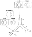
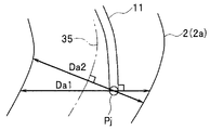
- FIG. 2A is a diagram showing a part of a bronchus and a bronchial shape image.
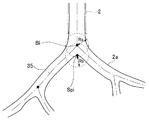
- FIG. 2B is a diagram showing a state in which the diameter of the bronchus is calculated over time after being inserted into the bronchus.
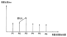
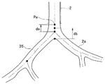
- FIG. 2C is a diagram showing the position where the bronchial diameter is calculated and the size of the calculated bronchial diameter.
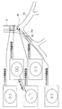
- FIG. 2D is a diagram illustrating candidate information displayed on a monitor when an instruction to perform positioning again is issued.
- FIG. 3A is a diagram illustrating a configuration of an endoscope apparatus including a stereo endoscope that performs stereo measurement.
- FIG. 3A is a diagram illustrating a configuration of an endoscope apparatus including a stereo endoscope that performs stereo measurement.
- FIG. 3A is a diagram illustrating a configuration of an endoscope apparatus including a stereo
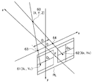
- FIG. 3B is an explanatory diagram illustrating a relationship in which the position of the measurement target for performing stereo measurement is imaged on the imaging surfaces of the left and right imaging elements.
- FIG. 3C is a diagram illustrating an example in which an image obtained by imaging the inside of the bronchus using a stereo endoscope is displayed on a monitor screen.
- FIG. 3D is an explanatory diagram for calculating a bronchial diameter from the image of FIG. 3C.
- FIG. 3E is an explanatory diagram for calculating a bronchus diameter by stereo measurement using a single imaging device.
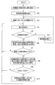
- FIG. 4 is a flowchart showing an example of processing contents in the first embodiment.
- FIG. 5 is an explanatory diagram for obtaining the bronchial diameter.
- FIG. 6 is an explanatory diagram when the bronchial diameter is acquired by a method different from that in FIG. 5.
- FIG. 7 is an explanatory diagram of a position where a bronchial diameter is acquired.
- FIG. 8 is an explanatory diagram of a position where the bronchial diameter is acquired with a setting different from that in FIG.
- FIG. 9 is an explanatory diagram for obtaining a bronchial diameter.
- FIG. 10 is an explanatory diagram when the bronchial diameter is acquired by a method different from that in FIG. 9.
- FIG. 11 is an explanatory diagram when a change in the area of a dark portion in an endoscopic image is detected.
- FIG. 12 is an explanatory diagram when a change in the shape of a branch in an endoscopic image is detected.
- FIG. 13 is an explanatory diagram when a change in the length of a spar in an endoscopic image is detected.
- FIG. 14 is an explanatory diagram when a change in the angle of a spar in an endoscopic image is detected.
- FIG. 15 is an explanatory diagram when a change in the field of view of an endoscopic image is detected.
- FIG. 16 is an explanatory diagram when a change other than a bronchial branch in an endoscopic image is detected.
- FIG. 17 is an explanatory diagram when a change in blurring of a characteristic portion in an endoscopic image is detected.
- the endoscope system 1 As shown in FIG. 1, the endoscope system 1 according to the first embodiment of the present invention is inserted into a bronchus 2 (FIG. 2A) as a predetermined luminal organ in a patient as a subject to be examined.
- An endoscope apparatus 4A provided with an endoscope 3A and an insertion support apparatus 5 that is used together with the endoscope apparatus 4A and that supports the insertion of the endoscope 3A are mainly configured.
- the endoscope apparatus 4A performs signal processing on the endoscope 3A, a light source apparatus 6 that supplies illumination light to the endoscope 3A, and an image sensor 7 that constitutes an imaging unit mounted on the endoscope 3A. It has a camera control unit (abbreviated as CCU) 8A as a signal processing device, and a monitor 9A that displays an endoscopic image generated by the CCU 8A.
- CCU camera control unit
- the endoscope 3 ⁇ / b> A has a flexible elongated insertion portion (or endoscope insertion portion) 11 and an operation portion 12 provided at the rear end of the insertion portion 11.
- the part 13 is provided with an illumination window and an observation window.
- a light guide 14 that transmits illumination light is inserted into the insertion unit 11 and the operation unit 12, and an incident end of the light guide 14 is connected to the light source device 6 and is generated by a light source lamp or LED (not shown) in the light source device 6. The illuminated light is incident on the incident end.
- the illumination light transmitted by the light guide 14 is emitted forward from an emission end (tip surface) attached to the illumination window.
- an objective lens 15 that forms an objective optical system for imaging a subject is attached to the observation window, and an imaging element 7 such as a CCD is disposed at the imaging position.
- An imaging device 16 is formed as an imaging means for imaging the inside of the bronchus 2 as a predetermined luminal organ into which the insertion portion 11 is inserted.
- the image sensor 7 is connected to the CCU 8A via a signal line inserted through the insertion unit 11 and the operation unit 12.
- the CCU 8A generates an image signal of a captured image corresponding to an optical image formed on the imaging surface of the image sensor 7 by an image signal generation circuit (not shown) therein, and outputs the image signal to the monitor 9A.
- the monitor 9A displays the image (moving image) of the image signal as an endoscopic image (also referred to as a captured image).
- the insertion portion 11 of the endoscope 3A is provided with a bendable bending portion 19 at the rear end of the distal end portion 13, and the operator performs an operation of rotating the bending operation knob 20 provided in the operation portion 12, for example.
- the bending portion 19 can be bent in any direction, up and down, left and right.
- the bending operation knob 20 includes an up / down bending operation knob for bending in the up / down direction and a left / right bending operation knob for bending in the left / right direction.
- an endoscope apparatus 4B shown in FIG. 3A may be adopted.
- the endoscope apparatus 4B includes a stereo endoscope 3B capable of three-dimensional measurement (stereo measurement), a light source device 6, and a CCU 8B and a CCU 8B that perform signal processing on the two imaging elements 7a and 7b provided in the stereo endoscope 3B. And a stereo display monitor 9B for displaying the generated stereo image signal.
- Left and right objective lenses 15a and 15b are arranged at a predetermined interval in the left-right direction at the distal end portion 13 of the insertion portion 11 of the stereo endoscope 3B, and the left and right imaging elements 7a and 7b are disposed at respective imaging positions.
- a stereo image pickup device 16 ' having left and right image pickup devices 16a and 16b is arranged.
- the left and right objective lenses 15a and 15b and the left and right imaging devices 16a and 16b have the same characteristics. Further, a light guide 14 that transmits illumination light from the light source device 6 is inserted into the insertion portion 11. The distal end of the light guide 14 is attached to the illumination window of the distal end portion 13, and the transmitted illumination light is emitted from the illumination window to illuminate a subject such as an affected part in the body cavity.
- the left and right imaging elements 7a and 7b that image the illuminated subject are inputted with the photoelectrically converted imaging signals to the imaging control units 18a and 18b in the CCU 8B, and the imaging control units 18a and 18b generate left and right image signals.
- the stereo image signal generator 18c To the stereo image signal generator 18c.
- the stereo image signal generation unit 18c generates a stereo display image signal from the left and right image signals and outputs the stereo display image signal to the stereo display monitor 9B.
- the stereo display monitor 9B displays an image signal for stereo display, and a user such as an operator can stereoscopically view the subject by displaying the image signal for stereo display.
- the left and right image signals generated by the imaging control units 18a and 18b are input to the measurement calculation unit 18d, and the left and right image signals are used for stereo measurement using the principle of triangulation on the captured image.
- the distance between two points can be measured.
- the bronchial diameter Den can be measured.
- Information such as the bronchial diameter Den calculated by the measurement calculation unit 18d is output to the image processing unit 25.
- a video signal generated by the imaging control unit 18 a (or 18 b) is also output to the image processing unit 25.
- various measurements such as the distance between the two points, the distance between the line connecting the two points and the distance between the points, the area, the depth, and the surface shape can be performed. It is also possible to obtain the distance (object distance) from the optical center 63 of the left objective lens 15a or the optical center 64 of the right objective lens 15b to the subject.
- optical data indicating the characteristics of the distal end portion 13 of the endoscope 3B and the objective lenses 15a and 15b is used.
- a plane including both of the two imaging planes is indicated by PL, and the center of the right imaging plane (on the optical axis of the objective lenses 15a and 15b not shown in FIG.
- O L are indicated by O R.
- a method for calculating three-dimensional coordinates from a stereo image there is a method disclosed in Japanese Patent Application Laid-Open No. 2011-027911.
- the measurement point 61 on the image corresponding to one measurement point 60 of the bronchial diameter on the imaging surface in FIG. 3B and The bronchial diameter Den is calculated by designating 62 and a point corresponding to the other measurement point.
- the display screen 71 of the monitor 9B shows a state in which the bronchus 72 in the endoscopic image and the next bronchial bifurcation 73 on the peripheral side of the bronchi 72 are displayed.
- the range of the screen 71 is divided by blocks as indicated by a mesh 74, and an area in which the average luminance in each block is a predetermined value or less is extracted.
- FIG. 3D shows the detection block 75 extracted in this manner with diagonal lines. And the measurement point 60a and the measurement point 60b are set by making the place with the largest diameter of the detection block 75 into the bronchus diameter of a measuring object.
- the measurement points 60a and 60b may be specified in the direction in which the distance between the measurement points 60a and 60b is the largest.
- the above calculation is performed on both the left screen and the right screen constituting the stereo image, and points corresponding to the measurement point 60a and the measurement point 60b are obtained on the left screen and the right screen, respectively. Then, if the point corresponding to the measurement point 60a on the left screen is calculated as the measurement point 61 in FIG. 3B and the measurement point 62 corresponding to the measurement point 60a on the right screen, the position of the measurement point 60 can be obtained. Since the same calculation is performed on the left screen and the right screen corresponding to the measurement point 60b, three-dimensional coordinates corresponding to 60 at both ends of the bronchial diameter can be obtained. Den can be calculated.
- the monocular (single) imaging device 16 of FIG. Stereo measurement may be performed as follows using the provided endoscope 3A.
- the operator bends the bending portion 19 on the distal end side of the insertion portion 11 left and right and picks up images with the left and right imaging devices in FIG. 3B.
- the bronchial diameter may be calculated by stereo measurement.
- the distal end of the insertion portion 11 is set near the center line of the bronchus 2, and the operator curves the bending portion 19, for example, to the left side.
- the objective lens 15 and the imaging element 7 at the first imaging position 16a ′ are indicated by 15a ′ and 7a ′, respectively.
- the surgeon After imaging at the first imaging position 16a ′, the surgeon curves the bending portion 19 to the right, and makes the tip contact the right inner wall of the bronchus 2 as shown by a two-dot chain line in FIG. 3E.
- the second imaging position 16b ′ corresponding to the state of imaging with the right imaging device 16b in FIG. 3B is set.
- the objective lens 15 and the imaging element 7 at the second imaging position 16b ′ are indicated by 15b ′ and 7b ′, respectively. Imaging is performed at the second imaging position 16b '.
- Information such as the number and the pixel pitch is checked in advance and stored in the information recording unit 27 or the like.
- the bending portion 19 is bent by a distance D ′ corresponding to the optical centers 63 ′ and 64 ′ in FIG. 3E corresponding to the left and right optical centers 63 and 64 in FIG. It can be calculated from a corner (or an operation amount of the bending operation knob 20) or the like. Further, the three-dimensional position of the measurement point 60 ′ can be calculated from the information of the measurement points 61 ′ and 62 ′ on the image pickup devices 7a ′ and 7b ′ with respect to the measurement point 60 ′ corresponding to the measurement point 60 in FIG. 3B. Also, the bronchial diameter can be calculated by designating two points, one position of the bronchial diameter and the other position as the measurement point 60 '.
- the bronchial diameter may be calculated using the endoscope 3A of FIG.
- the insertion support device 5 performs CT data as three-dimensional image information of a patient generated by known CT (Computed Tomography) for a patient to be examined by the endoscope 3A or 3B.
- CT data capturing unit 21 for capturing the image data via a portable storage medium such as a DVD, a Blu-ray disc, or a flash memory, and CT as image recording means for recording the CT data captured by the CT data capturing unit 21 And an image data recording unit 22.
- the CT image data recording unit 22 may store CT data generated as a CT (as three-dimensional image information of a patient as a subject) via a communication line, the Internet, or the like.
- the CT image data recording unit 22 can be configured by a hard disk device, a flash memory, a DVD, or the like.
- the CT image data recording unit 22 constituting the image recording means includes a CT image data separated from the CT data and a first coordinate system (CT coordinate system) corresponding to the CT image data separated from the CT data. ) Using the associated image information recording unit 22a that records as associated image information associated with the three-dimensional position data.
- the insertion support device 5 includes a luminal organ extraction circuit as a luminal organ extraction means for extracting three-dimensional image data of the bronchi 2 as a predetermined luminal organ from the CT image data of the CT image data recording unit 22.
- the bronchus extraction part 23 which becomes.
- the bronchus extraction unit 23 obtains 3D shape information (shape data) representing the hollow shape of the bronchus 2 and 3D shape from the extracted 3D data (more specifically, 3D volume data) of the bronchi 2.
- Image information (image data) is generated. That is, the bronchial extraction unit 23 includes a bronchial shape image generation unit 23a as a bronchial shape image generation unit that generates a bronchial shape image 2a as a hollow three-dimensional bronchial shape image from the extracted three-dimensional data of the bronchi 2. Have.
- the bronchi extracting unit 23 extracts the three-dimensional position data in the first coordinate system (or CT coordinate system) corresponding to the three-dimensional data in association with the three-dimensional data.
- the bronchus extraction unit 23 is a correspondence information recording unit 23b including a memory that records correspondence information in which the three-dimensional data of the bronchi 2 (that is, bronchial shape data) and the three-dimensional position data are associated with each other.
- the association image information recording unit 23b records bronchus diameter data at a designated (three-dimensional) position using a lookup table or the like.
- bronchial diameter data corresponding to the designated position can be read from the association information recording unit 23b, and bronchial diameter data can be acquired. Note that the bronchial diameter may be acquired from the bronchial shape data without using the association information recording unit 23b.
- the insertion support device 5 is a virtual endoscope corresponding to an endoscope image generated by imaging of the imaging device 16 or 16a, 16b provided at the distal end portion 13 of the insertion portion 11 in the endoscope 3A or 3B. It has a VBS image generation unit 24 as virtual endoscope image generation means for generating a virtual endoscope image (referred to as a VBS image) as a mirror image.
- VBS image virtual endoscope image generation means for generating a virtual endoscope image (referred to as a VBS image) as a mirror image.
- characteristic information including an imaging system related to the imaging device 16 at the distal end portion 13 of the endoscope 3A is, for example, Input from the input device 31 via the control unit 26.
- characteristic information regarding the imaging device 16 may be input from the input device 31 to the VBS image generation unit 24 without going through the control unit 26.
- the VBS image generation unit 24 is a three-dimensional position of the imaging device 16 (also referred to as the three-dimensional position of the distal end of the insertion unit 11) arranged in the distal end portion 13 of the endoscope 3A actually inserted into the bronchus 2. Based on the information, the characteristic information for imaging the subject in the bronchus 2 by the imaging device 16, and the bronchial shape data, the inside of the bronchus 2 is endoscopically set with the three-dimensional position (also simply referred to as position) as the viewpoint position. A VBS image for virtually drawing the captured endoscopic image is generated.
- the VBS image generation unit 24 can generate a VBS image corresponding to the change. Therefore, for example, when the position of the distal end of the insertion unit 11 and the (axis) direction of the distal end are designated by the CT coordinate system, the VBS image generation unit 24 generates a VBS image corresponding to the designation of the position and direction.
- the insertion support device 5 controls the image processing unit 25, the image processing unit 25, and the like that align the endoscope image input from the CCU 8A and the VBS image of the VBS image generation unit 24 by image matching.
- a control unit 26 as a control unit to perform and an information recording unit 27 constituting an information recording unit that records predetermined information such as a VBS image for supporting insertion under the control of the control unit 26 as candidate information.
- the insertion support apparatus 5 includes an MPR image generation unit 28 that generates a CT tomographic image (referred to as an MPR image) as a multi-section reconstruction image based on the CT image data recorded in the CT image data recording unit 22, and an MPR image.
- the path setting unit 29 determines the target from the insertion start position (of the insertion unit 11) in the bronchi 2 from the CT image data and the bronchial shape image 2a. It has a function of a route data generation unit 29a that generates route data to a target position in the vicinity of the part 36.
- the endoscope system 1 further includes an input device 31 including a keyboard and a pointing device for inputting setting information to the route setting unit 29. Further, the surgeon can input parameters and data when performing image processing from the input device 31 to the image processing unit 25, and can select and instruct the control operation to the control unit 26. .
- the route setting unit 29 sends information on the set route to the VBS image generation unit 24, the MPR image generation unit 28, and the control unit 26.
- the VBS image generation unit 24 and the MPR image generation unit 28 generate a VBS image and an MPR image along the route, respectively, and the control unit 26 controls the operation of each unit along the route.
- the image processing unit 25 receives an endoscopic image (also referred to as an actual image or simply an image) generated by the CCU 8A and a VBS image generated by the VBS image generation unit 24.
- the bronchial shape image 2a generated by the bronchial shape image generating unit 23a is also input to the image processing unit 25.
- the alignment processing unit 25a by the image processing unit 25 is installed.
- the three-dimensional position (position) of the distal end of the insertion portion 11 is estimated (or calculated) by image matching at.
- a three-dimensional position (known position) that can be specified from the bronchial shape image 2a by the CT coordinate system, such as the entrance of the bronchus 2 or the carina K (see FIG. 2A), or its neighboring position is set as a moving image matching start position.
- the VBS image generation unit generates a VBS image based on the position information.
- the alignment processing unit 25a of the image processing unit 25 is a three-dimensional position (a known position) that can be specified from the bronchial shape image 2a by the CT coordinate system (first coordinate system), such as the entrance of the bronchus 2 or a carina, or the vicinity thereof.
- the distal end of the insertion portion 11 is set at the position, and a state where the position of the distal end of the insertion portion 11 can be estimated (or calculated) by the CT coordinate system is set.
- the alignment processing unit 25a of the image processing unit 25 compares the endoscopic image and the VBS image, and a condition in which the comparison result is set (an error that can ensure a predetermined accuracy). Start matching image within. Therefore, the image processing unit 25 includes an image comparison unit 25b as an image comparison unit that compares the endoscopic image and the VBS image, and the alignment processing unit 25a uses image comparison performed by the image comparison unit 25b. To perform alignment processing by image matching.
- the alignment processing unit 25a of the image processing unit 25 calculates the position of the distal end of the insertion unit 11 and the axial direction of the distal end (the viewpoint direction or the line-of-sight direction of the imaging device 16).
- a state in which the position coordinates in the coordinate system (first coordinate system) and information indicating the axial direction (also referred to as posture) can be specified (acquired) is set.
- the position of the distal end of the insertion unit 11 thereafter is determined by the CT coordinate system (first coordinate system) based on the image comparison result by the image comparison unit 25b using the registered information. It becomes possible to obtain as information associated with the position at. That is, the image processing unit 25 includes a position estimation unit 25c that acquires the position of the distal end of the insertion unit 11 by estimation as a position information acquisition unit that acquires the position (information) of the distal end of the insertion unit 11. The position estimation unit 25c also acquires the position of the tip of the insertion unit 11 based on the image comparison result by the image comparison unit 25b.
- the image processing unit 25 is inserted under the CT coordinate system in the state after the alignment by the alignment processing unit 25a in the operation of inserting the insertion unit 11 into the deep side (peripheral side) of the bronchus 2.
- the position where the tip of the part 11 has moved is estimated from the comparison result of both the endoscopic image and the VBS image.
- the position estimation unit 25c uses the VBS image (output from the VBS image generation unit 24) when the distal end of the insertion unit 11 is moved on a path substantially along the core line 35, and the current endoscopic image. Is selected by image processing, and the three-dimensional position corresponding to the selected VBS image is calculated (estimated) as the position of the tip of the insertion unit 11. As described above, the position estimation unit 25 c calculates (estimates) the posture of the insertion unit 11 as well as the position of the distal end.
- the distal end of the insertion unit 11 may be moved at a position deviated from the core wire 35. Therefore, the VBS image generation unit 24 generates a VBS image at a position eccentric from the core wire 35 by an appropriate distance.
- the processed VBS image may be output to the alignment processing unit 25a. In this way, the range of position estimation by image matching can be expanded.
- the movement amount of the distal end of the insertion unit 11 and the moved position are calculated (estimated) from the difference amount between the two positions estimated by the position estimation unit 25c.
- the position estimation unit 25c calculates (estimates) a distance between the estimated position and a specific position such as a branch point (a position that can be specified by the CT coordinate system) in the feature region of the bronchus 2. You can also For this reason, the position estimation unit 25c determines the position of the distal end of the insertion unit 11 estimated by the position estimation unit 25c and a feature region such as a branched region in the bronchus 2 as a predetermined luminal organ. It has a function of a distance calculation unit as a distance calculation means for calculating the distance.
- the image processing unit 25 has a function of the position estimation unit 25c as a position information acquisition unit that acquires information on the position of the distal end of the insertion unit 11 by estimation.
- the alignment processing unit 25a may be defined as a configuration including the function of the position estimation unit 25c.
- the distal end of the insertion portion 11 is used in the same meaning as the distal end of the endoscope 3A.
- the image processing unit 25 generates an image to be displayed on the monitor 32 as an image display unit under the control of the display control unit 26 a that controls display in the control unit 26.
- the image processing unit 25 normally outputs an image signal (video signal) of the bronchial shape image 2a generated by the bronchial shape image generation unit 23a to the monitor 32.
- the bronchial shape image 2a is displayed on the monitor 32 as a two-dimensional tomographic image cut out in a cross section along the direction passing through the center of the lumen, for example.
- the display is not limited to a two-dimensional tomographic image, and a three-dimensional image may be displayed.
- a three-dimensional image for example, it may be displayed in a projection view by a parallel projection method or in a perspective view so that the inside of the lumen can be seen.
- a core line 35 passing through the center of the lumen of the bronchus 2 is also displayed on the bronchial shape image 2 a displayed on the monitor 32.
- the core wire 35 is generated by, for example, the bronchial shape image generation unit 23a, but the image processing unit 25 may generate the core wire 35.
- the image processing unit 25 has a function of an image generation unit 25d that generates an image or the like that superimposes the position of the distal end of the insertion unit 11 estimated by the position estimation unit 25c together with the core wire 35 on the bronchial shape image 2a. .
- the core wire 35 and the position of the distal end of the insertion portion 11 are displayed on the bronchial shape image 2 a representing the three-dimensional shape of the bronchus 2.
- the insertion operation of the insertion portion 11 can be easily performed by referring to the display. Further, by performing an operation of inserting along the core wire 35, the position of the distal end of the insertion portion 11 by image matching can be estimated in a short time. Further, the image processing unit 25 detects a change amount of the lumen diameter of a predetermined lumen organ based on the position information of the tip of the insertion unit 11 estimated by the position estimation unit 25c. As a means, a bronchial diameter change detection unit 25e that detects a change in bronchial diameter (in the case of bronchi 2 as a predetermined luminal organ) is provided.
- the bronchial diameter change amount detection unit 25e includes a bronchial diameter acquisition unit as a bronchial diameter acquisition unit that acquires the bronchial diameter from the CT coordinate system corresponding to the current tip position of the insertion unit 11 estimated by the position estimation unit 25c.
- the function of the bronchial diameter comparing unit as a bronchial diameter comparing means for comparing the bronchial diameter acquired by the bronchial diameter acquiring unit with a preset reference bronchial diameter is provided.
- the bronchial diameter acquisition unit detects the amount of change, that is, the amount of change in the bronchial diameter, by sequentially acquiring the bronchial diameter at each position of the estimated tip of the insertion unit 11 during the insertion operation of the insertion unit 11. .
- the bronchial diameter comparison unit compares the current bronchial diameter acquired sequentially with the reference bronchial diameter.
- the case where the current bronchus diameter is smaller than the reference bronchus diameter is set as a first condition for recording predetermined information including a VBS image.
- the image processing unit 25 is an image change as an image change amount detection unit that detects a change amount of a feature portion in an endoscopic image (also simply referred to as an image) captured by the image capturing device 16. It has the quantity detection part 25g.
- the present embodiment includes the bronchial diameter change amount detection unit 25e as the first change amount detection unit and the image change amount detection unit 25g as the second change amount detection unit.
- the bronchial diameter change amount detection unit 25e as the first change amount detection means is used for detection (determination) as to whether or not the first condition is satisfied.
- the image change amount detection unit 25g as the second change amount detection unit satisfies the second condition of whether or not the change amount of the characteristic part in the endoscopic image is larger than the set value ⁇ Dth. Used to detect In this embodiment, in a state where the first condition is satisfied, information including the VBS image is recorded when the second condition is satisfied (a predetermined condition is satisfied).
- the image change amount detection unit 25g is a bronchial diameter change amount detection unit 25h that detects a change amount of the bronchial diameter (inner diameter of the bronchus 2) as a feature portion, a brightness change amount in the branch region, or a feature region in the branch region.
- a brightness change amount detection unit 25i that detects a change amount of brightness
- a shape change amount detection unit 25j that detects a shape change amount in a branch region or a shape change amount of a feature portion in a branch region.
- the shape change amount detection unit 25j detects the amount of change in the length or angle of a spar (branch point or branch boundary) where the lumen of the bronchus 2 diverges (branches) as the shape change amount of the branch region (characteristic portion).
- the brightness change amount detector 25i has a function of a visual field defect detector 25l described later. The present invention is not limited to the case where the brightness change amount detection unit 25i has the function of the visual field defect detection unit 25l.
- the control unit 26 generates the route data generated by the route data generation unit 29a (before insertion of the insertion unit 11 of the endoscope 3A) based on the position of the distal end of the insertion unit 11 estimated by the position estimation unit 25c. You may make it correct
- control unit 26 determines whether or not a detection result by the bronchial diameter change detection unit 25e and a detection result by the image change detection unit 25g satisfy a predetermined condition for recording. It has the function of.
- condition determination unit 26b in the control unit 26 determines that the predetermined condition is satisfied, information on the position and orientation of the distal end of the insertion unit 11 estimated by the position estimation unit 25c when it is determined that the predetermined condition is satisfied.
- the information recording unit 27 records predetermined information in association with the VBS image corresponding to the position and orientation information, that is, position and image information (as candidate information to be presented at the time of realignment).
- the information recording unit 27 is based on the detection result by the bronchial diameter change amount detection unit 25e and the detection result by the image change amount detection unit 25g, and information on the position and orientation of the distal end of the insertion unit 11 and the position. And a function of information recording means for recording predetermined information as candidate information associated with the VBS image corresponding to the posture information.
- the condition determination unit 26b of the control unit 26 has a function of an information recording control unit 26c as an information recording control unit that performs control to record predetermined information in the information recording unit 27.
- the information recording control unit 26c has a bronchial diameter detected by a bronchial diameter change detecting unit 25e serving as a lumen diameter change detecting unit that is smaller than a reference bronchus diameter and is detected by the image change detecting unit 25g.
- the information recording unit 27 controls to record predetermined information including the VBS image.
- the condition determination unit 26b in the control unit 26 determines whether or not the detection result by the bronchial diameter change detection unit 25e and the detection result by the image change detection unit 25g satisfy a predetermined condition for recording. Instead of performing the determination, it may be determined whether or not the bronchial diameter change amount detection unit 25e and the image change amount detection unit 25g satisfy the first condition and the second condition, respectively. For this reason, the image processing unit 25 may have the function of the condition determination unit 26b.
- the display control unit 26a of the control unit 26 is used to perform input again in order to perform alignment again, for example, when the operator thinks that the accuracy of the estimated position of the distal end of the current insertion unit 11 is low.
- predetermined information recorded in the information recording unit 27 is read and displayed as candidate information on the monitor 32 via the image processing unit 25. Control to do.
- the image processing unit 25 includes an image generation unit 25d that generates an image to be displayed by superimposing the candidate information read from the information recording unit 27 on the bronchial shape image 2a. Specifically, the position and posture of the distal end of the insertion unit 11 and the VBS image corresponding to the position and posture are superimposed and displayed on the bronchial shape image 2a. As will be described later, FIG. 2D displays the position of the distal end of the insertion portion 11 on the bronchial shape image 2a displayed on the monitor 32 at a position corresponding to the position, and a VBS image corresponding to the position. A state of being superimposed and displayed in association with the position (by a line) is shown.
- the surgeon performs positioning again with reference to the candidate information, and the positioning processing unit 25a or the position estimating unit 25c determines the position and posture information of the distal end of the insertion unit 11 in the coordinate system of the bronchus 2 (CT coordinate system). ) Can be obtained in a state of being associated with. Then, by re-alignment, the position estimation unit 25c can perform an operation of ensuring the predetermined accuracy and reinserting the distal end of the insertion unit 11 into the deep side of the bronchus 2 from the re-aligned position. .
- the detection result by the bronchial diameter variation detection unit 25e satisfies the first condition
- the detection result by the image variation detection unit 25g satisfies the second condition (that is, the first condition).
- the position and orientation of the distal end of the insertion portion 11 when the determination result is obtained (estimated)
- the position and orientation Predetermined information including the corresponding VBS image is recorded in the information recording unit 27 as candidate information.
- predetermined information serving as candidate information may be recorded in the information recording unit 27 so as to include at least the position and the position of the tip.
- predetermined information also simply referred to as information
- an appropriate amount (or number) of candidate information is displayed. Can be displayed (or presented) on the monitor 32.
- the image change amount detection unit 25g detects a change amount of a characteristic part such as a bronchus diameter related to the bronchus 2 as a predetermined luminal organ in an endoscopic image captured by the imaging device 16, and at least the Based on the detection result by the image change amount detection unit 25g, predetermined information including the position and posture (information) at the distal end of the insertion unit 11 at the time of the detection result and the VBS image corresponding to the position and posture.
- the information is recorded in the information recording unit 27 (as candidate information to be presented when realignment is performed).
- a user such as a surgeon easily grasps conditions or conditions for recording information in order to perform an operation of inserting the insertion unit 11 while observing an endoscopic image captured by the imaging device 16.
- the candidate information presented when re-alignment is performed is set such that the amount of change in the feature in the endoscopic image changes sensitively to the movement of the position of the tip of the insertion unit 11. Therefore, it is easy to perform alignment by image comparison.
- the information recorded in the information recording unit 27 includes the position and orientation of the distal end of the insertion unit 11 and the corresponding VBS image, and further includes an endoscopic image corresponding to the position and orientation information. It may be recorded.
- the image processing unit 25 temporarily stores the endoscopic image and the VBS image when performing image matching by comparing both the endoscopic image and the VBS image, or the image processing work area.
- An image memory 26f used as An image memory 25f may be provided outside the image processing unit 25.
- the input device 31 includes a first condition relating to a change amount of the inner diameter of the bronchus 2 detected by the bronchial diameter change amount detection unit 25e and a change in the characteristic portion detected by the image change amount detection unit 25g. You may make it the structure which has the designation
- the information recording unit 27 records the predetermined information (position and image information) serving as the candidate information described above, as well as the condition information of the first condition and the condition information of the second condition regarding the second condition It may be possible to have a condition information recording unit 27a that records in advance.
- the condition recording unit 27a may be provided separately from the information recording unit 27.
- the condition information of the first condition includes (a) the difference (change amount) between the preset reference bronchus diameter Dre and the current bronchial diameter Da (at the distal end of the insertion portion 11), (b ′) This is the difference (change amount) between the reference bronchial diameter Dre and the current bronchial diameter at the reference position set by the user.
- (b ′) is further subdivided, (b) the difference (change amount) between the bronchial diameter Dre of the bifurcation portion having the preset number of branches and the current bronchial diameter Da, (c) any position set by the user Difference (change amount) between the reference bronchus diameter Dre and the current bronchus diameter Da at (d), (d) the reference bronchus diameter Dre and the current bronchus at the position of the endoscope tip having a preset endoscope insertion length It is good also as a difference (change amount) of diameter Da.
- the condition information of the second condition includes (a) a change in the bronchial diameter (bronchial diameter calculated from the endoscopic image) Den in the endoscopic image, and (b) a display for displaying the endoscopic image or the endoscopic image. (C) a change in the shape of the branch in the endoscopic image, (d) a change in the length of the spar in the endoscopic image, (e) a change in the angle of the spar in the endoscopic image, ( f) poor visual field (in the endoscopic image), (g) large blurring of the endoscopic image, (h) changes such as other than bronchi appearing in the endoscopic image.
- a user such as an operator can select, for example, from the condition information of the first condition (a) to (d) and the condition information of the second condition (a) to (h) (for example, the input device 31). It may be possible to selectively specify from the specifying unit 31a.
- the control unit 26 has a function of a condition setting unit 26d that sets the first condition and the second condition in response to the designation by the designation unit 31a.
- the condition setting unit 26d may also set threshold information and the like used when the condition determination unit 26b makes a determination when setting the first condition and the second condition.
- the threshold information may also be recorded in the information recording unit 27 in association with the information on the first condition and the second condition. Further, only the condition information of one condition (for example, the second condition) in the information of the first condition and the second condition may be recorded in the condition information recording unit 27a.
- the position estimation unit 25c as the position information acquisition unit means fails to acquire the position information of the tip of the insertion unit 11 based on the comparison result of the image comparison unit 25b, or in the information recording unit 27
- an instruction signal for causing the recorded predetermined information to be presented as candidate information is generated, the position of the distal end of the insertion unit 11 in the predetermined information recorded in the information recording unit 27 in the bronchial shape image 2a
- a display control unit 26a for controlling to display a VBS image corresponding to the position of the tip, and the position estimation unit 25c or the alignment processing unit 25a from the information recording unit 27.
- the image processing unit 25 can be configured by a CPU (Central Processing Unit), but the alignment processing unit 25a to the image change amount detection unit 25g inside the image processing unit 25 are each other than the CPU. It may be configured by using dedicated hardware. Also, the control unit 26 in FIG. 1 may be configured by a CPU, or may be configured by using dedicated hardware other than the CPU.
- CPU Central Processing Unit
- the endoscope system 1 having such a configuration includes a CT image data recording unit 22 as an image recording unit that records three-dimensional image information in a subject acquired in advance, and a predetermined luminal organ from the three-dimensional image information.
- a bronchus extraction unit 23 as a luminal organ extracting means for extracting the bronchus 2 and the information on the predetermined luminal organ extracted by the luminal organ extracting means endoscopically from a predetermined viewpoint position.
- VBS image generation unit 24 as a virtual endoscopic image generation unit that generates a drawn virtual endoscopic image
- an imaging unit that is provided in the endoscope 3A or 3B and images the inside of the predetermined lumen organ
- the endoscope 3A Is a bronchial diameter change amount detection unit as a luminal diameter change amount detecting means for detecting the change amount of the luminal diameter of the bronchus 2 as the predetermined luminal organ based on the position information of the tip of the 3B insertion unit 11 25e, and an image change amount detection unit 25g as an image change amount detection unit that detects a change amount of the characteristic part related to the bronchus 2 as the predetermined luminal organ in the endoscopic image picked up by the image pickup unit; Based on the detection result of the lumen diameter change amount detection unit and
- FIG. 4 shows a typical process in this embodiment.
- the process in FIG. 4 starts.
- Initial setting processing is performed in the first step S1 in FIG.
- the surgeon inputs information used for insertion support in the present embodiment from the input device 31.
- the surgeon designates the first condition and the second condition from the designation unit 31a.
- the condition determination part 26b will be in the state which performs determination corresponding to the designated 1st condition and 2nd condition.
- the operator designates, as the first condition, (a) the difference between the preset bronchial diameter (reference bronchial diameter) Dre and the current bronchial diameter Da, and the second condition is the bronchial diameter in the endoscopic image.
- the case where the change of Den is designated will be described below as (A).
- the reference bronchial diameter Dre information is not recorded at an insertion site that does not require recording, for example, near the entrance of the bronchus 2, and desired information can be stored at the insertion site that the operator desires to record. To be able to record.
- the diameter of the bronchus is large at the insertion site such as the vicinity of the entrance of the bronchus 2 and the operator can easily operate as intended by the insertion unit 11. It's easy to figure out where you are. Further, since the region is in the vicinity of the position where the first alignment is performed, the position of the distal end of the insertion portion 11 can be estimated with high accuracy.
- the operation of inserting the insertion portion 11 becomes difficult, and the bronchus 2 also becomes thin, so that it tends to be difficult to understand where the tip position is in the bronchus 2.
- the luminal region is located at a distance away from the first aligned position, the accuracy of the position estimation tends to decrease. Therefore, the surgeon may desire information used as candidate information for performing realignment.
- the operator sets a reference bronchial diameter Dre corresponding to the bronchial diameter at the site desired to be recorded. As will be described later, it is possible to record only predetermined information that is effective candidate information that facilitates re-alignment in a luminal region that the operator desires to record.
- the endoscopic image is used when re-alignment is performed by comparing the images.
- An image portion having a large change amount in the mirror image can be set as a main comparison target portion. Then, by setting a comparison target portion having a large change amount, it is easy to visually perform re-alignment by image comparison and can be completed in a short time.
- the bronchial shape image generation unit 23a in step S2 determines the bronchial shape as a shape image of the bronchus 2 as shown in FIG. An image 2a is generated.
- the bronchial shape image 2a is output to the monitor 32 via the image processing unit 25, and the bronchial shape image 2a is displayed on the monitor 32 as shown in FIG. 2A.
- the core line 35 passing through the center of the lumen of the bronchus 2 is displayed on the bronchial shape image 2a.
- Each position of the core line 35 and the branch point Bi is a known three-dimensional position specified in the CT coordinate system.
- the operator inserts the insertion portion 11 of the endoscope 3A into the bronchus 2.
- the surgeon uses the image comparison unit 25b at a known position such as the entrance of the bronchus 2 to set the condition (predetermined) that the endoscopic image by the imaging device 16 (or 16 ′) and the VBS image are set. Alignment processing by image matching is performed so that they match within an error that can ensure the accuracy of (1).
- the imaging device 16 ′ one endoscopic image obtained by one imaging device 16a or 16b in the imaging device 16 ′ may be employed. Note that the order of steps S2 and S3 may be switched or performed in parallel.
- step S4 the operator inserts the distal end of the insertion portion 11 closer to the deeper side of the bronchus 2 than the aligned position.
- the position estimation unit 25c of the image processing unit 25 uses the image comparison unit 25b to determine the position and orientation of the tip of the insertion unit 11 at a fixed time interval or the like. It is determined whether or not the estimation is successful by matching.
- the estimated position and posture of the distal end of the insertion section 11 are acquired as shown in step S6, and the bronchial diameter Da corresponding to the (current) position of the distal end of the insertion section 11 is acquired. Is obtained (from the CT image data recording unit 22 or the bronchi extraction unit 23). These pieces of information are temporarily stored in the image memory 25f, for example, and referred to when necessary in the processing in FIG. Note that the bronchial diameter Den may also be calculated from the endoscopic image at the time of estimating the position and posture of the distal end of the insertion section 11 in step S6. Further, the estimated position of the distal end of the insertion portion 11 is displayed on the bronchial shape image 2a. As shown in FIG. 2A, the estimated position Pj is displayed at the corresponding position on the bronchial shape image 2a.
- step S7 after step S6, the bronchial diameter change amount detection unit 25e or the condition determination unit 26b of the control unit 26 determines whether or not the bronchial diameter Da acquired in step S5 is smaller than a preset reference bronchial diameter Dre. I do. If the acquired current bronchus diameter Da is not smaller than the reference bronchus diameter Dre, the process returns to step S4, and the operator inserts the insertion portion 11 into the deep side. On the other hand, if the acquired bronchial diameter Da is smaller than the reference bronchial diameter Dre in the determination process of step S7 in FIG. 4, the image change amount detection unit 25g (the bronchial diameter change amount detection unit 25h) in the next step S8.
- Detects (calculates) a change amount (difference) ⁇ Den of the bronchial diameter Den calculated from the endoscopic image. That is, the image change amount detection unit 25g calculates the bronchial diameter Den calculated from the endoscopic image at the current distal end position of the insertion unit 11 and the endoscopic image at the previously estimated distal end position of the insertion unit 11. The amount of change ⁇ Den from the calculated bronchial diameter Den is calculated.
- the bronchial diameter Den calculated from the endoscopic image is not an average value of the lumen of the bronchus 2 but includes a case of a non-circular shape spreading in the branching direction at the branching portion. For this reason, the bronchial diameter Den calculated from the endoscopic image may be larger than the reference bronchus diameter Dre that is almost circular in the lumen of the bronchus 2.
- the condition determination unit 26b of the control unit 26 determines whether or not the change amount ⁇ Den of the bronchial diameter is larger than the set value ⁇ Dth. If the change amount ⁇ Den of the bronchial diameter is not larger than the set value ⁇ Dth, the process returns to step S4.
- step S10 the condition determination unit 26b determines the position and posture of the distal end of the insertion unit 11 corresponding to the determination result of step S9.
- Predetermined information with the VBS image corresponding to the position and orientation is recorded in the information recording unit 27.
- step S9 instead of determining whether or not the bronchial diameter change amount ⁇ Den is greater than the set value ⁇ Dth, it may be determined whether or not the bronchial diameter change amount ⁇ Den is greater than or equal to the set value ⁇ Dth. .
- the bronchial diameter Den is acquired from the endoscopic image together with the position estimation. Shows how it was done.
- the estimated position Pj moves through the positions P1, P2,..., P6 as the current tip position P7.
- each position Pj indicated by a white circle in FIG. 2B is a position satisfying the first condition (step S7), and a position P7 indicated by a black circle is the current position.
- the outline of the change in the bronchial diameter Den calculated by the measurement calculation unit 18d and the like at each position Pj described above is as shown in FIG. 2B, and FIG.
- the positions P1 to P6 where the bronchial diameter Den is calculated and the state of change of the calculated bronchial diameter Den are shown.
- Information acquired at each of the positions P1 to P6 is temporarily stored in the image memory 25f or the like and used for comparison.
- the bronchial diameter Den greatly changes so that the bronchial diameter Den becomes a peak near the branch point Bi.
- the condition determination unit 26b provides, as information (candidate information), predetermined information with, for example, the position and orientation of the position P3 and the VBS image corresponding to the position and orientation of P3 when the position P2 changes to the position P3 Records in the recording unit 27.
- the bronchial diameter Den also changes from a large value to a small value when the position changes from the position P3 to the position P4, but is not recorded at the position P4 because it is recorded at the position P3.
- the information recording unit 27 responds with information on the position and orientation between P2 and P3.
- Information with the VBS image to be recorded may be recorded.
- the position P3 substantially the position of the branch point Bi
- information may be set to be selectively recorded in the vicinity of the position where the bronchial diameter Den is maximum or peak in the endoscopic image.
- the candidate information is presented, and the change in the portion corresponding to the bronchial diameter Den in the endoscopic image when the distal end of the insertion portion 11 is moved for realignment is large. It is easy to perform alignment by image comparison (candidate information in FIG. 2D described below corresponds to an example in which information is recorded in the vicinity of the branch points Bi and Bi + 1 where the bronchial diameter Den is maximum or peak).
- the operator pays attention to the bronchial diameter Den portion in the endoscopic image and adjusts the position and posture of the distal end of the insertion portion 11 so that the bronchial diameter Den portion is maximized.
- the adjustment content (adjustment policy) becomes clear as if it is easy to grasp the part of interest and that the value is adjusted to the maximum, so image matching ( It becomes easy to perform alignment by (image comparison).
- the portion to be noted is not clear, and the orientation of how to adjust the change in the position and posture of the distal end of the insertion portion 11 is also unclear. Takes time to align. If the movement distance from the aligned position is small by the alignment in step S3 described above, the position estimation unit 25c can perform position estimation with relatively high accuracy. However, if the movement distance increases, The accuracy of estimation may be reduced.
- step S5 If the position estimation is not successful in step S5, the display control unit 26a of the control unit 26 reads predetermined information recorded in the information recording unit 27 and sends it to the image processing unit 25 in step S11.
- the image processing unit 25 outputs an image signal of the presentation information to the monitor 32, and the monitor 32 presents candidate information. Then, the process returns to step S3.
- step S ⁇ b> 3 the surgeon performs alignment again with reference to the candidate information displayed on the monitor 32. After performing the alignment again, the process of FIG. 4 is repeated. In this way, the operation of inserting the insertion portion 11 into the distal side (deep side) of the bronchus 2 can be performed smoothly.
- FIG. 2D shows a display example of candidate information in the case of step S11. In the candidate information display example of FIG.
- the branch points Bi and Bi + 1 and the corresponding VBS images are displayed, for example, by connecting them with lines, and the branch point Bi-1 etc. on the trunk side (insertion side) with respect to the branch point Bi is also the same. You may display.
- predetermined information recorded in the vicinity of branch points Bi and Bi + 1 where the lumen that is a characteristic region in the bronchus 2 branches is displayed as candidate information in the case of realignment.
- candidate information narrowed down to the minimum necessary in the vicinity of each branch point suitable for re-alignment is displayed. Therefore, it becomes easy for the surgeon to perform the positioning again smoothly and in a short time.
- the information to be recorded is narrowed down according to the first condition and the second condition, it is possible to record predetermined information having an information amount suitable for performing re-alignment.
- FIG. 2D predetermined information recorded in the vicinity of branch points Bi and Bi + 1 where the lumen that is a characteristic region in the bronchus 2 branches is displayed as candidate information in the case of realignment.
- the candidate information displayed at the time of re-alignment is too much or insufficient, and the appropriate position is re-positioned. It takes time to make adjustments.
- information is recorded when the feature portion in the endoscopic image changes greatly with respect to the movement of the position of the distal end of the insertion portion 11, so that a user such as an operator can record the information. Is easy to grasp the conditions for recording information. Therefore, this embodiment can record predetermined information having an information amount suitable for performing re-alignment under conditions that are easy for the user to visually grasp.
- the feature portion in the endoscopic image with respect to the movement of the position of the distal end of the insertion portion 11 This reflects the characteristic that changes greatly, so that it becomes easier for the user to visually perform re-alignment by image matching.
- the current endoscopic image is read from the information recording unit 27 and displayed together with the VBS image (and endoscopic image) as candidate information to be displayed, as shown by a two-dot chain line in FIG. 2D. You may make it display as a synthesized image superimposed on the shape image 2a. Thus, when the current endoscopic image is displayed adjacent to the candidate information, it is possible to easily perform alignment by image comparison with the candidate information.
- the display position can be moved so that the VBS image on the candidate information side is superimposed on the display position of the current endoscopic image, or the endoscopic image on the candidate information side is displayed on the current endoscopic image.
- An image moving unit that allows the display position to be moved so as to overlap the position may be provided in the image processing unit 25.
- the current endoscopic image display position is configured to include an image moving unit that can be moved to the candidate information side VBS image display position or the candidate information side endoscopic image display position. Also good.
- the bronchial diameter change amount detection unit 25e acquires the bronchial diameter Da based on information on the position of the distal end of the insertion unit 11, it may be acquired by the method shown in FIGS.
- the bronchial diameter Da1 calculated from the lumen of the bronchus 2 on the plane perpendicular to the longitudinal direction (or axial direction) of the distal end of the insertion portion 11 is employed as shown in FIG.
- the bronchial diameter Da2 calculated along a plane perpendicular to the core wire 35 so as to include the distal end of the insertion portion 11 and a perpendicular extending from the distal end to the core wire 35 may be employed.
- the bronchial diameter variation detection unit 25e detects the variation in the lumen diameter of the predetermined luminal organ in a plane perpendicular to the longitudinal direction of the distal end based on the information on the position of the distal end of the insertion unit 11.
- the amount of change in the lumen diameter of the predetermined lumen organ in a plane perpendicular to the core line 35 that is the center line of the lumen of the bronchus 2 may be detected.
- the reference bronchial diameter Dre used for the first condition is set to one regardless of the patient.
- Set bronchial diameter for the purpose of setting an optimal reference bronchus diameter for each patient.
- the surgeon decides in advance the number of branches that should be recorded as candidate information to be referred to.
- the number of branches is identification information that is easily identified by numbering sequentially according to the order of the branching portions as portions where the lumen branches from the entrance in the bronchus.
- the bronchus diameter corresponding to the number of branches set in advance by the operator is calculated from the three-dimensional data of the bronchus extraction unit 23 or the CT image data recording unit 22, and the calculated bronchial diameter is set as the reference bronchial diameter Dre. After this setting, the same operation as the case (case) of (A) is performed using the set reference bronchial diameter Dre.
- the reference bronchus diameter Dre can be set according to the actual patient's bronchi. For this reason, even in the case of patients having different physiques, the reference bronchus diameter Dre corresponding to the bronchus of the patient into which the insertion portion 11 is actually inserted can be set appropriately. Further, the reference bronchus diameter Dre corresponding to the bronchus diameter at the position where the operator actually wants to record the candidate information can be set with high accuracy. Therefore, it is possible to record only effective information that is candidate information desired by the surgeon without wastefully recording information that does not require recording.
- one reference bronchus diameter Dre may be set and a condition for recording a bronchus diameter smaller than this value may be set. May be set, a second reference bronchus diameter may be set.
- the bronchial diameter Dre1 may be set to satisfy the bronchial diameter between the two reference bronchial diameters Dre0 and Dre1 as a condition for recording.
- a lower limit reference bronchus diameter is set, and the calculated current bronchus diameter Da is set to the lower limit side.
- the diameter of the bronchus is smaller than the reference bronchus diameter, it may be determined that the target lumen portion has been inserted and the recording operation may be terminated. Moreover, you may make it use the order by which the name is decided for every branch anatomically instead of the number of branches mentioned above.
- the position to be detected is a branch point on the core wire 35 as shown in FIG. It may be set near the position of Bi or Spur Spi. Alternatively, as indicated by a dotted line, the area may be limited to a radius Ra, Rb around the branch point Bi or the spur Spi. When such a region is set, it may be set for each branch point Bi or spur Spi. Also, unlike FIG. 7, as shown in FIG.
- the core 35 is a distance Pa from the bifurcation point Bi along the direction of the core 35 along the direction of the core 35 and returned to the entrance (basic) side of the bronchus 2 or a distance da from the spar Spi.
- the bronchial diameter Da1 along a plane perpendicular to the axial direction of the distal end of the insertion portion 11 as shown in FIGS. 9 and 10.
- the bronchial diameter Da2 along the plane perpendicular to the core line 35 or the bronchial diameter Da3 along the coordinate axis of the three-dimensional data in the CT coordinate system may be used.
- the maximum value / minimum value of the corresponding bronchus 2 only the right lung, only the left lung, both lungs, or only on the insertion path of the preset insertion unit 11 may be used. good.
- the bronchial diameter is calculated by the bronchial diameter Da1 along the plane perpendicular to the axial direction of the distal end of the insertion portion 11, the bronchial diameter Da2 along the plane perpendicular to the core 35, and CT.
- the bronchial diameter Da3 along the coordinate axis of the three-dimensional data in the coordinate system may be used.
- the case (C) has almost the same effect as the case (B).
- (D) Bronchial diameter Dre at the position of the distal end of the insertion portion 11 having a preset insertion length The surgeon sets the insertion length (endoscope insertion length) of the insertion unit 11 for which it is better to acquire candidate information in advance from the input device 31, and for example, distance estimation included in the position estimation unit 25c of the image processing unit 25 All the positions in the bronchus 2 that can be reached with the insertion length set in the three-dimensional data of the CT image data recording unit 22 or the bronchi extracting unit 23 are calculated by the function of the unit. Each bronchus diameter at each calculated position is calculated, and the average value is set as the reference bronchus diameter Dre.
- the bronchial diameter is calculated by calculating the bronchial diameter Da2 calculated on the plane perpendicular to the axial direction of the distal end of the insertion portion 11 and the bronchial diameter Da2 calculated on the plane perpendicular to the core wire 35.
- the bronchial diameter Da3 along the coordinate axis of the three-dimensional data in the CT coordinate system may be used.
- the maximum value / minimum value of the corresponding bronchus 2 only the right lung, only the left lung, both lungs, or only on the insertion path of the preset insertion unit 11 may be used. good.
- the brightness change amount detection unit 25i (of the image change amount detection unit 25g) acquires an endoscopic image at a predetermined time interval set in advance, and acquires the acquired endoscopic image.
- the operation of monitoring the area of the dark part is continuously performed.
- the position of the distal end of the insertion portion 11 when obtained is indicated by P1, P2,..., P5 in FIG.
- the area of the dark part refers to the total area of the image parts in which the brightness in the endoscopic image is a specified value or less.
- the bifurcation portion in the lumen portion on the front side of the distal end of the insertion portion 11 in the bronchi 2 is recognized as a dark portion.
- the change in the area of the dark part when moving from the position P1 to the position P2 is small, but the area of the dark part is greatly changed compared to the position P2 in order to approach the branching region branched at the position P3. .
- the brightness change amount detection unit 25i or the condition determination unit 26b detects that the area of the dark part has changed significantly more than the set value
- the brightness change amount detection unit 25i or the condition determination unit 26b Control is performed to record (predetermined) information including the VBS image.
- Information including a VBS image may be recorded in the information recording unit 27.
- the amount of change in brightness is not limited to the case of detecting from the amount of change in the area of the dark part, but the average value of the brightness of the endoscopic image is calculated, and the amount of change in which the average value is equal to or greater than the threshold value.
- information including the VBS image may be recorded in the information recording unit 27.
- the interval at which the endoscopic image is acquired may be linked with the timing at which the distal end position of the insertion portion 11 is acquired in addition to every predetermined time or every predetermined distance.
- the position is not limited to a position where the brightness, such as the area of a dark portion, has changed more than a set value, and may be a position before or after that.
- the amount of change in the feature portion in the image is adopted as the amount of change that is easy for the operator to visually compare. Even when displayed as, it is easy to visually perform the alignment state.
- FIG. 12 shows a state in which a branch-shaped portion of the bronchus 2 is extracted.
- the shape change amount detection unit 25j of the image change amount detection unit 25g determines the amount of change in the shape of the feature in the endoscopic image. Detect. More specifically, as shown by positions P1, P2,..., P5 shown in FIG. 12, for example, the shape change amount detection unit 25j obtains an endoscopic image at a constant interval or a constant time interval, and acquires the acquired endoscope. For example, the operation of monitoring the branch shape of the bronchus 2 is continuously performed in the mirror image.
- the change in the bronchial branch shape when moving from the position P1 to the position P2 is small, but at the position P3, the bronchial branch shape is larger than the position P2 in order to approach the branching region that is branched. It has changed.
- the shape change amount detection unit 25j detects that the bronchial bifurcation shape has changed significantly (greater than or equal to the set value)
- the information including the VBS image is recorded in the information recording unit 27 at the changed position (P3 in FIG. 12).
- the interval at which the endoscopic image is acquired may be linked with the timing at which the distal end position of the insertion portion 11 is acquired in addition to every predetermined time or every predetermined distance.
- a change amount that is easy for the operator to visually compare such as a change in the bronchial branch shape, is used as the change amount of the characteristic part in the image. In addition, it is easy to visually perform the alignment state.
- the spur change amount detection unit 25k of the image change amount detection unit 25g Detect the amount of change.
- the length of the spar is the length of the boundary at the bifurcation where the lumen of the bronchus 2 is bifurcated.
- positions P1, P2, At positions P1, P2,. For example, the operation of monitoring the length of the spar of the bronchi 2 is continuously performed in the acquired endoscopic image.
- FIG. 13B shows the relationship between the tip position Pj of the insertion portion 11 and the length of the spar.
- the change in the length of the spar when moving from the position P1 to the position P2 is small, but at the position P3, it approaches a branching region that branches.
- the length of the spar greatly changes compared to the position P2.
- the information recording unit 27 receives information including the VBS image at the changed position (P3 in FIG. 13). Control to record.
- the interval at which the endoscopic image is acquired may be linked with the timing at which the distal end position of the insertion portion 11 is acquired in addition to every predetermined time or every predetermined distance.
- (G) when the change amount of the feature part in the image is displayed as candidate information because the change amount that is easy for the operator to visually compare, such as the change of the bronchial branch shape, is adopted. In addition, it is easy to visually perform the alignment state.
- the spur change amount detection unit 25k of the image change amount detection unit 25g detects the spar angle (direction) in the endoscopic image. ) Is detected.
- the angle of the spar is an angle formed with a longitudinal direction of a boundary portion or a reference direction at a branch portion where the lumen of the bronchus 2 is bifurcated. As shown by positions P1, P2,..., P5 shown in FIG.
- the spar change amount detection unit 25k (of the image change amount detection unit 25g) acquires an endoscopic image at a constant interval or a constant time interval. Then, for example, the operation of monitoring the angle of the spar of the bronchi 2 is continuously performed in the acquired endoscopic image.
- FIG. 14B shows the relationship between the tip position Pj of the insertion portion 11 and the angle of the spar.
- the change in the angle of the spar when moving from the position P1 to the position P2 is small, but the position P3 is closer to the branch region that is branched. Since the surgeon twists the insertion portion 11, the angle of the spar greatly changes compared to the position P2.
- the spar change amount detection unit 25k detects that the angle of the spar has changed significantly (more than the set value)
- the information including the VBS image is recorded in the information recording unit 27 at the changed position (P3 in FIG. 14). Control to do.
- the interval at which the endoscopic image is acquired may be linked with the timing at which the distal end position of the insertion portion 11 is acquired in addition to every predetermined time or every predetermined distance.
- a change amount that is easy for the operator to visually compare such as a change in the shape of the bronchus, is used as the change amount of the feature in the image. In addition, it is easy to visually perform the alignment state.
- the visual field defect detection unit 25l of the image change amount detection unit 25g detects the occurrence of a visual field defect in the endoscopic image.
- Visual field defect (occurrence) is determined based on whether or not the endoscopic image taken inside the bronchus is visible to the extent that the branch or dark part on the distal end side of the lumen is visible, and the dirt covers the entire visual field.
- the visual field defect detection unit 251 determines that there is a visual field defect when the brightness of the endoscopic image becomes darker than the predetermined brightness and the dark region covers almost the entire endoscopic image. For this reason, for example, the brightness change amount detection unit 25i has the function of the visual field defect detection unit 25l.
- the visual field defect detection unit 25l (of the image change amount detection unit 25g) acquires, for example, an endoscopic image at regular intervals or regular time intervals.
- the operation to monitor visual field defects is continuously performed.
- the occurrence of a visual field defect is detected when moving from the position P2 to the position P3, and information including the VBS image is recorded in the information recording unit 27 at the position P2 immediately before the change.
- the interval at which the endoscopic image is acquired may be linked with the timing at which the distal end position of the insertion portion 11 is acquired in addition to every predetermined time or every predetermined distance.
- the amount of change in the feature portion in the image such as a visual field defect, is easily changed by the operator, so it is easy to grasp the state in which the information is recorded. .
- the shape change amount detection unit 25j described above has detected the change amount of the branch shape in the bronchus. However, when the shape changes from the branch shape to a structure or shape other than the branch shape, in other words, Information may be recorded when a change other than the shape is detected.
- (J) When detecting changes other than the branch of the bronchus in the endoscopic image, In this case, when the insertion unit 11 is inserted into the bronchus 2 as shown in FIG. 16, the shape change amount detection unit 25 j of the change amount detection unit 25 g The operation of monitoring whether or not a branch exists in the endoscopic image is continuously performed. When the surgeon curves the bending portion 19 of the insertion portion 11 or twists the insertion portion 11 and determines that the branch does not exist in the endoscopic image, the position immediately before that is determined. Information including the VBS image is recorded in the information recording unit 27.
- the shape change amount detection unit 25j acquires an endoscopic image at regular intervals or constant time intervals. For example, a branch shape portion is extracted from the acquired endoscopic image, and the operation for monitoring the presence or absence of the branch is continuously performed. Then, when moving from position P2 to position P3 in FIG. 16, it is determined that the state has changed to a state where no branch exists, and information including the VBS image is recorded in information recording unit 27 at position P2 immediately before the change. To control.
- the interval at which the endoscopic image is acquired may be linked with the timing at which the distal end position of the insertion portion 11 is acquired in addition to every predetermined time or every predetermined distance.
- a change amount that is easy for the operator to visually compare such as a change in the presence or absence of a branching shape, is employed. Easy to grasp.
- the image processing unit 25 receives the image signals sequentially input from the CCU 8A at a predetermined time interval (for example, 1/30 s or 1/60 s) and the first memory 81a and the first memory 81a in the image memory 25f. 2 alternately stored in the memory 81b.
- a predetermined time interval for example, 1/30 s or 1/60 s
- the latest n-th image In is stored in the second memory 81b
- the (n-1) -th image In-1 one frame or one field before is stored in the second memory 81b.
- the (n-1) th image In-1 captured in the adjacent frame or field and the nth image In are input to the shake amount calculation processing unit 82, and the shake amount calculation processing unit 82 receives one image (for example, For a point set in the image In), an operation for calculating a corresponding point in the other image as a motion vector amount representing a blur amount is performed.
- the motion vector amount calculated by the shake amount calculation processing unit 82 is input to the shake amount determination unit 83.
- the shake amount determination unit 83 regards the calculated motion vector amount as the shake amount, and the magnitude of the motion vector amount. It is determined whether (absolute value) exceeds a specified value, and information including a VBS image is recorded as candidate information according to the determination result.
- the condition determination unit 26b illustrated in FIG. 1 may be configured to have the function of the shake amount determination unit 83.
- the blur amount calculation processing unit 82 sets a W ⁇ H pixel range centered on the center point of the image In as a template, and searches for a corresponding point on the image In-1 corresponding to the center point.
- the search for corresponding points is performed, for example, by calculating SAD (Sum of Absolute Differences) of luminance. Assuming that the pixel value of the template is t (x, y) and the pixel value of the image to be searched is g (x, y), F (u, v) that is SAD at the coordinates (u, v) is generally ( 4) Calculated by the equation.
- the center coordinate of the image In-1 corresponding to the image In is set to (Ox, Oy), and F (Ox ⁇ W / 2 ⁇ u ⁇ Ox + W / 2, Oy ⁇ H / 2 ⁇ v ⁇ Oy + H / 2.
- u, v) is calculated.
- the coordinates (Ex, Ey) when F (u, v) is minimum are the corresponding points.
- the motion vector m is calculated by equation (5).
- m (Ex-Ox, Ey-Oy) (5) The above is the method for calculating the motion vector m.
- the shake amount determination unit 83 compares the magnitude of the motion vector m with a specified value. When it is determined that the magnitude of the motion vector m is larger than the specified value, the shake amount determination unit 83 determines that the shake change exceeding the specified value has occurred with respect to the information recording unit 27 and causes the information recording unit 27 to On the other hand, a recording instruction signal (or storage instruction signal) for recording a VBS image is output. Upon receiving this recording instruction signal, the information recording unit 27 records the image in the first memory 81a of the image memory 25f before the occurrence of the shake exceeding the specified value as a candidate image. The operation of recording the candidate image is performed every time a recording instruction signal is input, and the candidate image is accumulated in the information recording unit 27.
- the present invention includes the case of any combination of configurations and methods related to the first condition and the second condition in the above-described embodiment.
- the condition information recording unit 27a as the condition information recording unit has been described as recording information on a plurality of candidate conditions and candidate information that can be set as the first condition and the second condition, respectively.
- a plurality of condition information (or information) that can be set as the first condition and the second condition may be recorded without using the candidate information.
- the condition information desired by the operator or the like may be designated without recording a plurality of condition information (or information).
- the information recorded in the information recording unit 27 is displayed as candidate information as a display unit.
- the display (presentation) is described in FIG.
- the present invention is not limited to this case.
- information recorded in the information recording unit 27 at a predetermined timing may be displayed (presented) on the monitor 32 as display means as candidate information.
- control unit 26 matches the set time interval or condition
- control for reading information from the information recording unit 27 may be performed, and candidate information including a VBS image may be displayed on the monitor 32 via the image processing unit 25.
- An image comparison unit that compares the image information captured by the imaging unit and the virtual endoscopic image; and a display unit that displays the virtual endoscopic image recorded in the information acquisition unit at a predetermined timing.
- the information acquisition unit may acquire at least position information of the imaging unit based on the comparison result of the image comparison unit.
- the bronchial diameter detected by the bronchial diameter change detection unit 25e is smaller than the reference bronchus diameter Dre, and the change amount of a characteristic part such as a spur detected by the image change amount detection unit 25g changes to a set value or more.
- the information including the VBS image is recorded in the information recording unit 27.
- the information recording control unit 26c or the like changes the change amount to the maximum value or peak.
- the information recording unit 27 may record information including the position and posture of the distal end of the insertion unit 11 and the corresponding VBS image.
- the present invention is not limited to the configuration shown in FIG. 1 described above, for example, and may be only the basic configuration (element) described in claim 1. In this basic configuration, A configuration in which one or more components are selectively added may be used.
Landscapes
- Health & Medical Sciences (AREA)
- Life Sciences & Earth Sciences (AREA)
- Engineering & Computer Science (AREA)
- Surgery (AREA)
- Medical Informatics (AREA)
- Physics & Mathematics (AREA)
- Pathology (AREA)
- Veterinary Medicine (AREA)
- Public Health (AREA)
- Biomedical Technology (AREA)
- Heart & Thoracic Surgery (AREA)
- Biophysics (AREA)
- Molecular Biology (AREA)
- Animal Behavior & Ethology (AREA)
- General Health & Medical Sciences (AREA)
- Radiology & Medical Imaging (AREA)
- Nuclear Medicine, Radiotherapy & Molecular Imaging (AREA)
- Optics & Photonics (AREA)
- High Energy & Nuclear Physics (AREA)
- Signal Processing (AREA)
- Computer Vision & Pattern Recognition (AREA)
- Pulmonology (AREA)
- Physiology (AREA)
- Dentistry (AREA)
- Oral & Maxillofacial Surgery (AREA)
- Theoretical Computer Science (AREA)
- Psychiatry (AREA)
- Artificial Intelligence (AREA)
- Otolaryngology (AREA)
- Software Systems (AREA)
- Gynecology & Obstetrics (AREA)
- Human Computer Interaction (AREA)
- Computer Graphics (AREA)
- Computer Hardware Design (AREA)
- General Engineering & Computer Science (AREA)
- General Physics & Mathematics (AREA)
- Remote Sensing (AREA)
- Radar, Positioning & Navigation (AREA)
- Endoscopes (AREA)
- Apparatus For Radiation Diagnosis (AREA)
Priority Applications (4)
| Application Number | Priority Date | Filing Date | Title |
|---|---|---|---|
| CN201480003398.2A CN104883950B (zh) | 2013-03-27 | 2014-02-19 | 内窥镜系统 |
| JP2014549267A JP5715312B2 (ja) | 2013-03-27 | 2014-02-19 | 内視鏡システム |
| EP14776199.3A EP2918218A4 (de) | 2013-03-27 | 2014-02-19 | Endoskopsystem |
| US14/736,710 US9516993B2 (en) | 2013-03-27 | 2015-06-11 | Endoscope system |
Applications Claiming Priority (2)
| Application Number | Priority Date | Filing Date | Title |
|---|---|---|---|
| JP2013067408 | 2013-03-27 | ||
| JP2013-067408 | 2013-03-27 |
Related Child Applications (1)
| Application Number | Title | Priority Date | Filing Date |
|---|---|---|---|
| US14/736,710 Continuation US9516993B2 (en) | 2013-03-27 | 2015-06-11 | Endoscope system |
Publications (1)
| Publication Number | Publication Date |
|---|---|
| WO2014156378A1 true WO2014156378A1 (ja) | 2014-10-02 |
Family
ID=51623379
Family Applications (1)
| Application Number | Title | Priority Date | Filing Date |
|---|---|---|---|
| PCT/JP2014/053876 WO2014156378A1 (ja) | 2013-03-27 | 2014-02-19 | 内視鏡システム |
Country Status (5)
| Country | Link |
|---|---|
| US (1) | US9516993B2 (de) |
| EP (1) | EP2918218A4 (de) |
| JP (1) | JP5715312B2 (de) |
| CN (1) | CN104883950B (de) |
| WO (1) | WO2014156378A1 (de) |
Cited By (5)
| Publication number | Priority date | Publication date | Assignee | Title |
|---|---|---|---|---|
| JP2016214782A (ja) * | 2015-05-26 | 2016-12-22 | Mrt株式会社 | 気管支鏡の作動方法、マーキング用気管支鏡、切除標的領域の特定方法、及び、プログラム |
| US20170071504A1 (en) * | 2015-09-16 | 2017-03-16 | Fujifilm Corporation | Endoscope position identifying apparatus, endoscope position identifying method, and recording medium having an endoscope position identifying program recorded therein |
| JP2019072243A (ja) * | 2017-10-17 | 2019-05-16 | 国立大学法人千葉大学 | 内視鏡画像処理プログラム、内視鏡システム及び内視鏡画像処理方法 |
| JP2019170667A (ja) * | 2018-03-28 | 2019-10-10 | 日本光電工業株式会社 | 挿管システム |
| JP2020022563A (ja) * | 2018-08-06 | 2020-02-13 | ソニー・オリンパスメディカルソリューションズ株式会社 | 医療用観察装置 |
Families Citing this family (15)
| Publication number | Priority date | Publication date | Assignee | Title |
|---|---|---|---|---|
| JP6654038B2 (ja) * | 2015-12-22 | 2020-02-26 | 富士フイルム株式会社 | 内視鏡システム、プロセッサ装置、及び、内視鏡システムの作動方法 |
| JP6698699B2 (ja) * | 2015-12-25 | 2020-05-27 | オリンパス株式会社 | 画像処理装置、画像処理方法およびプログラム |
| JP6608111B2 (ja) * | 2016-09-28 | 2019-11-20 | 富士フイルム株式会社 | 医用画像保存再生装置および方法並びにプログラム |
| JP6779089B2 (ja) * | 2016-10-05 | 2020-11-04 | 富士フイルム株式会社 | 内視鏡システム及び内視鏡システムの駆動方法 |
| JP6828465B2 (ja) * | 2017-01-30 | 2021-02-10 | セイコーエプソン株式会社 | 内視鏡操作支援システム |
| JP6745748B2 (ja) * | 2017-03-16 | 2020-08-26 | 富士フイルム株式会社 | 内視鏡位置特定装置、その作動方法およびプログラム |
| US10638084B2 (en) * | 2017-03-28 | 2020-04-28 | Olympus Corporation | Endoscope apparatus, endoscope system, and endoscope image recording method |
| US10646288B2 (en) * | 2017-04-12 | 2020-05-12 | Bio-Medical Engineering (HK) Limited | Automated steering systems and methods for a robotic endoscope |
| CN110769731B (zh) * | 2017-06-15 | 2022-02-25 | 奥林巴斯株式会社 | 内窥镜系统、内窥镜用处理系统、图像处理方法 |
| WO2020044523A1 (ja) * | 2018-08-30 | 2020-03-05 | オリンパス株式会社 | 記録装置、画像観察装置、観察システム、観察システムの制御方法、及び観察システムの作動プログラム |
| WO2020194472A1 (ja) * | 2019-03-25 | 2020-10-01 | オリンパス株式会社 | 移動支援システム、移動支援方法、および移動支援プログラム |
| WO2021038495A1 (en) * | 2019-08-30 | 2021-03-04 | Auris Health, Inc. | Instrument image reliability systems and methods |
| WO2022245847A1 (en) * | 2021-05-17 | 2022-11-24 | Jihad Ali Mustapha | A measuring device and a measurement method thereof |
| US20230053189A1 (en) * | 2021-08-11 | 2023-02-16 | Terumo Cardiovascular Systems Corporation | Augmented-reality endoscopic vessel harvesting |
| US20230404670A1 (en) * | 2022-05-27 | 2023-12-21 | Covidien Lp | Creating a navigation pathway to a target in the lung and method of navigating to the target |
Citations (8)
| Publication number | Priority date | Publication date | Assignee | Title |
|---|---|---|---|---|
| JP2005338551A (ja) * | 2004-05-28 | 2005-12-08 | Olympus Corp | 工業用内視鏡装置 |
| WO2007129493A1 (ja) | 2006-05-02 | 2007-11-15 | National University Corporation Nagoya University | 医療画像観察支援装置 |
| JP2009279250A (ja) | 2008-05-23 | 2009-12-03 | Olympus Medical Systems Corp | 医療機器 |
| JP2011027911A (ja) | 2009-07-23 | 2011-02-10 | Olympus Corp | 内視鏡装置、計測方法、およびプログラム |
| WO2011094518A2 (en) * | 2010-01-28 | 2011-08-04 | The Penn State Research Foundation | Image-based global registration system and method applicable to bronchoscopy guidance |
| WO2011101754A1 (en) * | 2010-02-18 | 2011-08-25 | Koninklijke Philips Electronics N.V. | System and method for tumor motion simulation and motion compensation using tracked bronchoscopy |
| JP2011212244A (ja) * | 2010-03-31 | 2011-10-27 | Fujifilm Corp | 内視鏡観察を支援するシステムおよび方法、並びに、装置およびプログラム |
| JP2012505695A (ja) * | 2008-10-20 | 2012-03-08 | コーニンクレッカ フィリップス エレクトロニクス エヌ ヴィ | 画像に基づくローカライゼーション方法及びシステム |
Family Cites Families (7)
| Publication number | Priority date | Publication date | Assignee | Title |
|---|---|---|---|---|
| US6773393B1 (en) * | 1999-08-05 | 2004-08-10 | Olympus Optical Co., Ltd. | Apparatus and method for detecting and displaying form of insertion part of endoscope |
| US20040059263A1 (en) * | 2002-09-24 | 2004-03-25 | Spiration, Inc. | Device and method for measuring the diameter of an air passageway |
| JP4245880B2 (ja) * | 2002-08-30 | 2009-04-02 | オリンパス株式会社 | 内視鏡装置 |
| US8465452B2 (en) * | 2003-02-21 | 2013-06-18 | 3Dt Holdings, Llc | Devices, systems, and methods for removing stenotic lesions from vessels |
| US20070203396A1 (en) * | 2006-02-28 | 2007-08-30 | Mccutcheon John G | Endoscopic Tool |
| JP5188879B2 (ja) * | 2008-05-23 | 2013-04-24 | オリンパスメディカルシステムズ株式会社 | 医療機器 |
| WO2012095755A1 (en) * | 2011-01-13 | 2012-07-19 | Koninklijke Philips Electronics N.V. | Intraoperative camera calibration for endoscopic surgery |
-
2014
- 2014-02-19 JP JP2014549267A patent/JP5715312B2/ja active Active
- 2014-02-19 EP EP14776199.3A patent/EP2918218A4/de not_active Withdrawn
- 2014-02-19 CN CN201480003398.2A patent/CN104883950B/zh active Active
- 2014-02-19 WO PCT/JP2014/053876 patent/WO2014156378A1/ja active Application Filing
-
2015
- 2015-06-11 US US14/736,710 patent/US9516993B2/en active Active
Patent Citations (8)
| Publication number | Priority date | Publication date | Assignee | Title |
|---|---|---|---|---|
| JP2005338551A (ja) * | 2004-05-28 | 2005-12-08 | Olympus Corp | 工業用内視鏡装置 |
| WO2007129493A1 (ja) | 2006-05-02 | 2007-11-15 | National University Corporation Nagoya University | 医療画像観察支援装置 |
| JP2009279250A (ja) | 2008-05-23 | 2009-12-03 | Olympus Medical Systems Corp | 医療機器 |
| JP2012505695A (ja) * | 2008-10-20 | 2012-03-08 | コーニンクレッカ フィリップス エレクトロニクス エヌ ヴィ | 画像に基づくローカライゼーション方法及びシステム |
| JP2011027911A (ja) | 2009-07-23 | 2011-02-10 | Olympus Corp | 内視鏡装置、計測方法、およびプログラム |
| WO2011094518A2 (en) * | 2010-01-28 | 2011-08-04 | The Penn State Research Foundation | Image-based global registration system and method applicable to bronchoscopy guidance |
| WO2011101754A1 (en) * | 2010-02-18 | 2011-08-25 | Koninklijke Philips Electronics N.V. | System and method for tumor motion simulation and motion compensation using tracked bronchoscopy |
| JP2011212244A (ja) * | 2010-03-31 | 2011-10-27 | Fujifilm Corp | 内視鏡観察を支援するシステムおよび方法、並びに、装置およびプログラム |
Non-Patent Citations (1)
| Title |
|---|
| See also references of EP2918218A4 |
Cited By (11)
| Publication number | Priority date | Publication date | Assignee | Title |
|---|---|---|---|---|
| JP2016214782A (ja) * | 2015-05-26 | 2016-12-22 | Mrt株式会社 | 気管支鏡の作動方法、マーキング用気管支鏡、切除標的領域の特定方法、及び、プログラム |
| US20170071504A1 (en) * | 2015-09-16 | 2017-03-16 | Fujifilm Corporation | Endoscope position identifying apparatus, endoscope position identifying method, and recording medium having an endoscope position identifying program recorded therein |
| JP2017055954A (ja) * | 2015-09-16 | 2017-03-23 | 富士フイルム株式会社 | 内視鏡位置特定装置、方法およびプログラム |
| US10561338B2 (en) * | 2015-09-16 | 2020-02-18 | Fujifilm Corporation | Endoscope position identifying apparatus, endoscope position identifying method, and recording medium having an endoscope position identifying program recorded therein |
| JP2019072243A (ja) * | 2017-10-17 | 2019-05-16 | 国立大学法人千葉大学 | 内視鏡画像処理プログラム、内視鏡システム及び内視鏡画像処理方法 |
| JP7126673B2 (ja) | 2017-10-17 | 2022-08-29 | 国立大学法人千葉大学 | 内視鏡画像処理プログラム及び内視鏡システム |
| JP2019170667A (ja) * | 2018-03-28 | 2019-10-10 | 日本光電工業株式会社 | 挿管システム |
| JP7037410B2 (ja) | 2018-03-28 | 2022-03-16 | 日本光電工業株式会社 | 挿管システム |
| US11612312B2 (en) | 2018-03-28 | 2023-03-28 | Nihon Kohden Corporation | Intubation system |
| JP2020022563A (ja) * | 2018-08-06 | 2020-02-13 | ソニー・オリンパスメディカルソリューションズ株式会社 | 医療用観察装置 |
| US11638000B2 (en) | 2018-08-06 | 2023-04-25 | Sony Olympus Medical Solutions Inc. | Medical observation apparatus |
Also Published As
| Publication number | Publication date |
|---|---|
| JP5715312B2 (ja) | 2015-05-07 |
| EP2918218A1 (de) | 2015-09-16 |
| US9516993B2 (en) | 2016-12-13 |
| CN104883950B (zh) | 2016-12-28 |
| EP2918218A4 (de) | 2016-08-03 |
| US20150272423A1 (en) | 2015-10-01 |
| CN104883950A (zh) | 2015-09-02 |
Similar Documents
| Publication | Publication Date | Title |
|---|---|---|
| JP5715312B2 (ja) | 内視鏡システム | |
| JP5715311B2 (ja) | 内視鏡システム | |
| JPWO2014156378A1 (ja) | 内視鏡システム | |
| US9326660B2 (en) | Endoscope system with insertion support apparatus | |
| EP2888991B1 (de) | Endoskopsystem | |
| US9066086B2 (en) | Methods for generating stereoscopic views from monoscopic endoscope images and systems using the same | |
| JP5750669B2 (ja) | 内視鏡システム | |
| WO2017212725A1 (ja) | 医療用観察システム | |
| JP6022133B2 (ja) | 医療装置 | |
| JP7385731B2 (ja) | 内視鏡システム、画像処理装置の作動方法及び内視鏡 | |
| US9345394B2 (en) | Medical apparatus | |
| WO2018230099A1 (ja) | 内視鏡システム、内視鏡システムの作動方法 | |
| JP7441934B2 (ja) | 処理装置、内視鏡システム及び処理装置の作動方法 | |
| US10694929B2 (en) | Medical equipment system and operation method of medical equipment system | |
| JP6335839B2 (ja) | 医療装置、医療画像生成方法及び医療画像生成プログラム | |
| WO2016039292A1 (ja) | 内視鏡システム |
Legal Events
| Date | Code | Title | Description |
|---|---|---|---|
| ENP | Entry into the national phase |
Ref document number: 2014549267 Country of ref document: JP Kind code of ref document: A |
|
| 121 | Ep: the epo has been informed by wipo that ep was designated in this application |
Ref document number: 14776199 Country of ref document: EP Kind code of ref document: A1 |
|
| WWE | Wipo information: entry into national phase |
Ref document number: 2014776199 Country of ref document: EP |
|
| NENP | Non-entry into the national phase |
Ref country code: DE |