WO2014156319A1 - 電子制御装置のプログラム書き換え方法、電子制御装置、及び書き換え装置 - Google Patents
電子制御装置のプログラム書き換え方法、電子制御装置、及び書き換え装置 Download PDFInfo
- Publication number
- WO2014156319A1 WO2014156319A1 PCT/JP2014/052822 JP2014052822W WO2014156319A1 WO 2014156319 A1 WO2014156319 A1 WO 2014156319A1 JP 2014052822 W JP2014052822 W JP 2014052822W WO 2014156319 A1 WO2014156319 A1 WO 2014156319A1
- Authority
- WO
- WIPO (PCT)
- Prior art keywords
- electronic control
- control device
- rewriting
- program
- data
- Prior art date
- Legal status (The legal status is an assumption and is not a legal conclusion. Google has not performed a legal analysis and makes no representation as to the accuracy of the status listed.)
- Ceased
Links
Images


Classifications
-
- G—PHYSICS
- G06—COMPUTING OR CALCULATING; COUNTING
- G06F—ELECTRIC DIGITAL DATA PROCESSING
- G06F8/00—Arrangements for software engineering
- G06F8/60—Software deployment
- G06F8/65—Updates
- G06F8/654—Updates using techniques specially adapted for alterable solid state memories, e.g. for EEPROM or flash memories
Definitions
- the present invention relates to an electronic control device or the like connected to a vehicle communication network, and relates to a method for rewriting an electronic control device program via a communication network, an electronic control device having a rewriting function, and a rewriting device.
- ECU Electronic Control Unit
- a plurality of ECUs are installed to control the vehicle's powertrain system, body system, safety system, information system, etc., and these ECUs are connected by an in-vehicle network system (CAN protocol) to exchange necessary data. Implement and control the entire vehicle.
- CAN protocol in-vehicle network system
- control program acquired from the program rewriting device is temporarily stored in the RAM of the gateway, and then each ECU is CAN-reprogrammed from the gateway so that the program data is stored in the RAM of the gateway.
- the control program can be written in each ECU without maintaining the connection state of the rewriting device.
- Patent Document 2 in a gateway that transmits rewrite data for rewriting a program to a plurality of ECUs connected via a plurality of different CAN buses, transmission of rewrite data of the ECUs connected to the different buses is performed in parallel. This is configured to be performed.
- rewriting data is once transmitted from the rewriting device to the gateway using high-speed communication, and then the rewriting data is transmitted from the gateway to each ECU via CAN communication. It is the structure which performs CAN reprogramming between. Therefore, a gateway device is indispensable between the rewriting device and the rewriting target ECU, and there is a problem in that the component cost and manufacturing cost for the gateway increase.
- the rewriting data is transmitted from the rewriting device to the ECU via the gateway, the configuration of the entire rewriting system becomes complicated and there is a problem that the failure rate of the system increases.
- the present invention has been made to solve the above-mentioned problems, and its purpose is to rewrite a program in parallel without going through an intermediary device such as a gateway when performing CAN reprogramming to a plurality of ECUs. To provide a rewriting method that shortens the rewriting time of a program.
- a vehicle program rewriting method relates to a vehicle electronic control device having a rewritable storage medium and communication means for communicating with the outside via a communication network.
- the electronic control device includes a program configured to connect a rewriting device to the communication network and rewrite a program in a storage medium of the electronic control device via the communication means, and the electronic control device includes a plurality of electronic control devices.
- the rewriting device Connected to the same communication network, the rewriting device transmits data to a plurality of electronic control devices connected to the communication network simultaneously with a single identifier, and the plurality of electronic control devices are different from each other.
- the response data is transmitted to the rewriting device using the identifier, so that the plurality of identical electronic control devices can be It is configured to be able to perform a rewrite operation of the same program in parallel Te.
- the data transmission from the rewriting device can be simultaneously transmitted to a plurality of electronic control devices, and the writing device can identify each response of the plurality of electronic control devices.
- Program rewrite operation can be performed.
- the communication network used by the electronic control device according to claim 2 for communication with the rewriting device is a bus according to the CAN protocol
- the identifier used for the response by the electronic control device is a non-volatile for individual identification by the electronic control device. It is generated from the individual identification data held in the sex memory.
- the individual identification data used by the electronic control device according to claim 3 is stored in an area that is not rewritten by program rewriting of the nonvolatile memory of the electronic control device.
- the same individual identification data can be used for the same electronic control device.
- the individual identification data used by the electronic control device according to claim 4 is characterized by having information on any one of a manufacturing factory, a manufacturing line, a manufacturing number, and a manufacturing date.
- the individual identification data used by the electronic control device according to claim 5 is printed on the outside of the housing of the electronic control device in a format corresponding to the mechanical reading means.
- the electronic control device has a normal mode in which data is transmitted to the communication network at regular intervals when mounted on a vehicle, and a program rewrite mode in the case of rewriting a program. The periodic data transmission to the communication network from is stopped.
- the rewriting device responds from the electronic control device by reading the individual identification data printed on the casing of the electronic control device to be rewritten with a mechanical reading means before rewriting the program. Characterized by identifying an identifier, This makes it possible to specify an identifier to which the electronic control device responds efficiently before rewriting the program.
- the rewriting device collates an identifier specified from the individual identification data printed on a casing of the electronic control device with an identifier used in response data of the electronic control device at the time of program rewriting. Thus, a connection error of the electronic control device, a communication network problem, or a failure of the communication circuit of the electronic control device is detected.
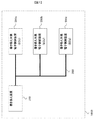
- FIG. 1 is a schematic block diagram showing a program rewriting method for an electronic control device according to the present embodiment, an electronic control device having a rewriting function, and a rewriting device (the whole is referred to as a “rewriting system”).
- a rewriting device 100 and electronic control devices (ECUs) 200a, 200b, and 200c to be rewritten are connected via a communication network (CAN) 300.
- each electronic control unit is, for example, an engine control unit or a shift control unit that is mounted on a car later, and the mounting is performed after rewriting the program.
- FIG. 1 shows a system configuration in which three rewriting target ECUs are connected to one rewriting device 100
- the number of rewriting target ECUs is not limited to three, but one to three or more. There is no restriction on the number of ECUs to be rewritten.
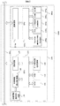
- FIG. 2 is a schematic block diagram showing details of the rewriting device 100 of the rewriting system of the present embodiment and the ECU 200a to be rewritten.
- the rewrite target ECU 200a includes a CPU 220a that controls the rewrite target ECU, a flash ROM 230a that is a rewritable storage medium in which a program is stored, a RAM 240a that temporarily stores data exchanged by communication, and various types used in the ECU.
- a data storage unit 250a for storing information and a communication circuit 210a for performing data communication via a network are provided.
- an input unit 260a for processing an external sensor input and the like and an output unit 270a for driving an external actuator are also provided.
- a flash ROM is described as an example of the rewritable storage medium 230a. However, any rewritable storage medium that stores a program may be used, and an EEPROM, a hard disk, and the like are also applicable. Is possible.
- the rewriting device 100 includes a CPU 120 that controls the rewriting device, a ROM 130 that stores a program, a RAM 140 that temporarily stores data exchanged by communication, and a data storage unit that stores past information such as rewriting results. 150, a communication circuit 110 for performing data communication via a network, an external information reading unit 170 for reading external information printed on the ECU to be rewritten, and a signal received from the external information reading unit It has an external information reading circuit 160 for converting into possible digital data.
- the rewriting device 100 can be configured by connecting, for example, a communication interface connected to a communication network (CAN) to a personal computer or the like and a barcode scanning device as external information reading means.
- a communication interface connected to a communication network (CAN) to a personal computer or the like and a barcode scanning device as external information reading means.
- CAN communication network
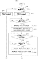
- the CPU 220a reads a program stored in the flash ROM 230a, expands it in the RAM 240a, and executes it. By executing the program after being expanded in the RAM 240a, the Flash ROM 230a in which the program is stored can be rewritten. When this program is executed, the CPU 220a determines in step S100 whether the program rewrite mode or the normal mode. (There are a plurality of determination methods for determining whether or not the program rewrite mode is set, and will be described later as Embodiments 1 and 2 in FIG. 5).
- step S100 If it is determined that the normal mode is determined in step S100, it is determined that the vehicle is mounted, and the process proceeds to step S105. After starting the regular data transmission to the communication network, the process proceeds to the end process of FIG. On the other hand, if it is determined that the program rewrite mode is selected, the process proceeds to step S110, the periodic data transmission to the communication network is stopped, and the program rewrite mode is entered.
- step S120 while the periodical data transmission to the communication network is stopped, reception of rewrite start request data from the rewrite device 100 is awaited.
- the process proceeds to step S130, and the individual identification data stored in the nonvolatile memory of the ECU (the flash ROM 230a that is not rewritten by the program rewriting or the area of the data storage unit 250a). Use to generate a CAN identifier (CAN ID). Details of the individual identification data will be described later with reference to FIG.
- CAN ID CAN identifier
- the individual identification data is stored in a specific area (Flash ROM 230a or data storage unit 250a) of the nonvolatile memory of the ECU 200a that is not rewritten by program rewriting, and is printed in some form outside the casing of the ECU 200a. .
- This may be in any format that can be read mechanically by the rewriting device 100, for example, a barcode (one-dimensional or two-dimensional) format or an IC tag format.
- step S140 of FIG. 3 response data is transmitted to the rewriting device 100 using the generated CAN ID.
- the processing so far is preprocessing until rewrite data is received.
- the CAN ID used by the ECU for the response data in the processing after the next step S150 uses the CAN ID generated in step S130.
- step S150 it is determined whether writing of all areas has been completed or whether writing has failed. In the case of the first time, since writing has not yet been performed, the process proceeds to the next step S160.
- step S160 the process waits until rewrite data is received.
- the process proceeds to step S170, where the received data is written in the flash ROM 230a, and in step S180, response data for rewriting data reception is transmitted. Thereafter, the process returns to step S150 again, and the process is repeated until writing is performed for all areas.
- step S150 If it is determined in the determination process in step S150 that all area writing has been completed or writing has failed, the process proceeds to step S190 in FIG.
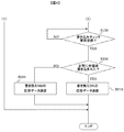
- step S190 the process waits until a write check request for all areas is received.
- a write check request is received from the rewriting device 100, it is confirmed in step S200 whether or not writing has been normally performed on all areas. If writing has been normally performed on all areas, response data on rewriting OK in step S210.
- step S200 if writing to the entire area has not been performed normally, rewrite NG response data is transmitted in step S205, and the rewrite process is completed.
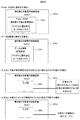
- FIG. 5 is used to show an embodiment of a method for discriminating between the program rewrite mode and the normal mode.
- Example 1 when saving in the flash ROM (when saving in the flash ROM) (when saving in the data storage unit), a determination flag indicating whether or not the program rewrite mode is set is stored in the flash ROM 230a or the data storage unit 250a, and is read and determined. It is.
- the discrimination flag is read and used for setting the program rewrite mode, so that the rewrite target ECU always operates in the program rewrite mode. If the ECU is in this state, the program can be rewritten by connecting only the minimum terminals (power supply terminal, communication network terminal, GND terminal, etc.) used for rewriting. The state can be simplified.
- Example 2 In FIG. 5 (when the input sensor value is determined by a combination that cannot be mounted in the vehicle) (when the sensor is not connected to the input sensor terminal), the program is rewritten in the state of the input terminal provided in the ECU.
- This is a method for determining whether or not the mode.
- the state of the sensor input at the input unit 260a cannot be a vehicle-mounted state (for example, in the case of an ECU that controls the transmission, the input range SW is in a combination that cannot normally be taken).
- This is a method for discriminating from the program rewrite mode. In the case of this method, since it is possible to select the program rewrite mode operation or the normal operation only by the terminal state of the rewrite target ECU, it is not necessary to prepare unnecessary data in the nonvolatile memory.
- the input terminal state may be set as a judgment condition for setting the program rewrite mode operation when the input terminal state is open (a state where no sensor is connected).
- the sensor is connected when the ECU is mounted on the vehicle, so it operates in the normal operation mode, and when the program is rewritten, all sensor inputs are left open so that it can be used in the program rewrite mode. Can do.
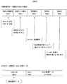
- the individual identification data shown in FIG. 6 shows an example of the data structure corresponding to the 29-bit extended CAN ID, and the total number of bits of the individual identification data is the same 29 bits as the number of bits used in the extended CAN ID ID. ing.
- the individual identification data includes information about a manufacturing factory, a manufacturing line, a manufacturing number, and a manufacturing date (year, day) so that the ECU can be individually identified.
- FIG. 6 shows a 29-bit data structure used for the extended CAN ID, for ECUs with a small production scale, only the minimum necessary data is used for the individual identification data, so that 11 bits of the standard CAN ID are used. It is also possible to use it as a data structure. Further, the DLC (4 bit) value of the CAN data structure and the data size and value of the ECU transmission data (0 to 64 bits) can be used in a value and size suitable for the content to be transmitted.
- the individual identification data printed outside the casing of the rewriting target ECU is read using the external information reading means 170 in step S300 of FIG. 7, and the solid identification data of the rewriting target ECU 100 is read into the RAM 140 via the external information reading circuit 160 and the CPU 120. Is stored.
- the external information reading means 170 uses a device that matches the print format of the solid identification data used by the ECU 200a. For example, a barcode (one-dimensional or two-dimensional) format is a barcode reader, and an IC tag format is an IC tag reader.
- step S310 it is determined whether or not this step S300 has been performed for all the ECUs to be rewritten. For example, when rewriting is performed by connecting five rewrite target ECUs in parallel, the process proceeds to step S320 after performing step S300 five times (for five ECUs).
- step S320 rewrite start request data is transmitted to all ECUs connected to the communication network using the same CAN ID.
- the same CAN ID is used for a plurality of ECUs connected to the same network, the same data can be transmitted to all ECUs by one data transmission.
- the CAN ID transmitted from the rewriting device to the ECU is predetermined to a specific ID value.
- step S330 it is confirmed whether response data has been received from all the ECUs connected in step S330. Since the CAN ID used by each ECU in response is equal to the individual identification data read in step S300, it is possible to identify whether there is a response from each ECU by the received CAN ID.
- step S330 after receiving response data from all ECUs, the process proceeds to the next step S340.
- step S340 it is determined whether or not all rewrite data (program of the rewrite target ECU) has been transmitted. At the time of the first transition to step S340, since rewrite data has not been transmitted yet, the process proceeds to the next step S350.
- step S350 rewrite data is transmitted to all ECUs connected to the communication network using the same CAN ID. Thereafter, in step S360, it is confirmed whether response data has been received from all connected ECUs. If responses have been received from all ECUs, the process returns to step S340, and whether all rewrite data has been transmitted. If all rewrite data has not been transmitted, the process of step S350 is performed again, and the next rewrite data is transmitted.
- the CAN protocol only a maximum of 8 bytes (64 bits) of data can be transmitted in one transmission of rewrite data, so that all rewrite data is transmitted by executing this rewrite data transmission a plurality of times.
- step S340 After all rewrite data is transmitted, the process proceeds from step S340 to step S370 in FIG. 8, and a write check request is transmitted to all ECUs connected to the communication network using the same CAN ID. Thereafter, whether or not response data has been received from all ECUs connected in step S380 is confirmed. If responses have been received from all ECUs, the process proceeds to step S390.
- step S390 the received data of each ECU is confirmed. At this point, it is determined that rewriting has been normally completed for the ECU that has returned the response of rewriting OK, and it is determined that rewriting has failed for the ECU that has returned the response of rewriting NG.
- a configuration may be adopted in which it is determined that a communication network connection error, a communication network problem, a failure in the communication circuit of the ECU, or the like has occurred with respect to the specific ECU, and the processing is interrupted.
- the electronic control device having a rewriting function, and the rewriting device according to the present embodiment
- mediation such as a gateway is performed.
- a program can be rewritten in parallel to a plurality of ECUs without using a device, and the rewriting time of the program can be shortened.
- Program rewriting system 100: Rewriting device, 200a, 200b, 200c ... Electronic control unit (ECU) to be rewritten, 110, 210a ... Communication circuit, 120, 220a ... CPU, 130 ... ROM, 230a ... Flash ROM, 140,240a ... RAM, 150,250a ... Data storage unit, 260a ... Input unit, 270a ... Output unit, 300 ... Communication network Bus, 160 ... external information reading circuit, 170 ... external information reading means.
- ECU Electronic control unit
Landscapes
- Engineering & Computer Science (AREA)
- Software Systems (AREA)
- General Engineering & Computer Science (AREA)
- Theoretical Computer Science (AREA)
- Computer Security & Cryptography (AREA)
- Physics & Mathematics (AREA)
- General Physics & Mathematics (AREA)
- Stored Programmes (AREA)
Abstract
複数のECUにCANリプログラミングを行う場合に、ゲートウェイなどの仲介装置を介さずに並行でプログラムを書き換えることで、プログラムの書き換え時間を短縮するようにした書き換え方法を提供する。 プログラム書き換えシステム1000は、書き換え装置100と1つ以上の書き換え対象ECU200a、200b、200cとが同一のネットワークバス300で接続された構成を持ち、書き換え装置100は予め定められた特定のIDを使用して書き換え対象ECU全てに対して同時にデータを送信し、書き換え対象ECUは個体識別データを使用してそれぞれ異なったIDを生成し、そのIDで書き換え装置にデータを送信する。
Description
本発明は、車両通信ネットワークに接続される電子制御装置等に関し、通信ネットワークを介して電子制御装置のプログラムを書き換える方法、書き換え機能を有する電子制御装置、書き換え装置に関する。
近年、走行性能、安全性、快適性、省資源、省エネルギー等を追求する目的で、自動車等の車両にも多くのマイクロプロセッサを含む電子制御装置(ECU(Electronic Control Unit)) が搭載されている。
車両のパワートレーン系、ボディ系、安全系、情報系等を制御するために複数のECUが搭載されており、これらECU同士が車載ネットワークシステム(CANプロトコル)で接続され、必要なデータのやりとりを実施し、車両全体の制御を行っている。
この車載ネットワークシステムを使用して、ECUのプログラム書き換えを行うCANリプログラミングが公知である。
特許文献1では、プログラム書き換え装置から取得された制御プログラムを、一旦ゲートウェイのRAMに蓄積し、その後ゲートウェイから各ECUをCANリプログラミングすることで、プログラムデータがゲートウェイのRAMに蓄積された後であれば、書き換え装置の接続状態を維持しなくても、ECUそれぞれに制御プログラムを書き込むことができるように構成したものである。
特許文献2では、複数の異なるCANバスを介して接続された複数のECUにプログラムを書き換えるための書き換えデータを送信するゲートウェイにおいて、それぞれの異なるバスに接続されたECUの書き換えデータの送信を並行して行うように構成したものである。
しかし、上述のプログラム書き換え方法は、書き換え装置から一旦ゲートウェイに高速通信を使用して書き換えデータを送信し、次にゲートウェイからそれぞれのECUにCAN通信を介して書き換えデータを送信し、ゲートウェイとECUの間でCANリプログラミングを行う構成である。そのため、書き換え装置と書き換え対象ECUの間にゲートウェイ装置が必要不可欠であり、ゲートウェイ分の部品コスト、製造コストが増加するという問題があった。
また、書き換え装置からゲートウェイを介し、書き換えデータをECUに送信するため、書き換えシステム全体の構成が複雑になり、システムの故障率が上がってしまうといった問題もある。
一方、ゲートウェイを使用せずに、複数のECUを並行でCANリプログラミングするには、書き換え装置を複数用意する必要があった。例えば10台のECUを並行でCANリプログラミングする場合には、10台の書き換え装置が必要になり、これもコストが増加する要因となる。
本発明は、上記課題を解決するためになされたものであり、その目的は、複数のECUにCANリプログラミングを行う場合に、ゲートウェイなどの仲介装置を介さずに並行でプログラムを書き換えることで、プログラムの書き換え時間を短縮するようにした書き換え方法を提供することである。
上述した目的を達成するために、請求項1に係る車両用プログラム書き換え方法は、書き換え可能な記憶媒体と、通信ネットワークを介して外部と通信するための通信手段を持つ車両用の電子制御装置に関して、前記電子制御装置は、前記通信ネットワークに書き換え装置を接続し、前記通信手段を介して前記電子制御装置の記憶媒体のプログラムを書き換え可能に構成したプログラムを有し、前記電子制御装置を複数個同一の通信ネットワークに接続し、前記書き換え装置から、前記通信ネットワークに接続されている複数の電子制御装置に対して単一の識別子で同時にデータの送信を行い、前記複数の電子制御装置はそれぞれ異なった識別子で前記書き換え装置に対して応答データを送信することで、前記複数の同一電子制御装置に対して並列で同一プログラムの書き換え動作を実行することができるように構成している。
これにより、書き換え装置からのデータ送信を複数の電子制御装置に同時に送信するとともに、複数の電子制御装置の応答それぞれを書込み装置が識別することが可能となり、複数の電子制御装置に対して並列でプログラムの書き換え動作が実施できるようになる。
請求項2に係る電子制御装置が書き換え装置との通信で使用する通信ネットワークは、CANプロトコルによるバスであり、前記電子制御装置が応答に使用する識別子は、電子制御装置が個体識別するために不揮発性メモリに保持している個体識別データから生成することを特徴とする。
これにより、電子制御装置自身の制御プログラムを変更することなく、個体識別データの設定を変更するのみで、複数の同一電子制御装置それぞれについて、重複しない識別子を割り当てることが可能となる。
請求項3に係る電子制御装置が使用する個体識別データは、前記電子制御装置の不揮発性メモリのプログラム書き換えにより書き換わらない領域に保存することを特徴とする。
これにより、プログラム書き換えを複数回実施する場合でも、同一の電子制御装置であれば、同一の個体識別データを使用することが可能となる。
請求項4に係る電子制御装置が使用する個体識別データは、製造工場、製造ライン、製造番号、製造日のいずれかの情報を有していることを特徴とする。
これにより、同一の電子制御装置であっても、重複しない個体識別データの設定が可能となる。
請求項5に係る電子制御装置が使用する個体識別データは、電子制御装置の筐体外部に機械的読み取り手段に対応した形式で印字されていることを特徴とする。
これにより、個体識別データを容易に取得可能となる。
請求項6に係る電子制御装置は、車両搭載時に一定の間隔で通信ネットワークにデータを送信する通常モードと、プログラムを書き換える場合のプログラム書き換えモードを有し、プログラム書き換えモード動作では、前記電子制御装置からの通信ネットワークへの定期的なデータ送信を停止することを特徴とする。
これにより、同一の識別子を複数の電子制御装置が送信することにより発生する通信ネットワークのエラー発生を防止することができ、複数の同一電子制御装置を同一の通信ネットワークに接続可能となる。
請求項7に係る書き換え装置は、プログラム書き換え前に、書き換え対象の前記電子制御装置の筐体に印字された前記個体識別データを機械的読み取り手段で読み取ることで、前記電子制御装置から応答される識別子を特定することを特徴とする、
これにより、プログラム書き換え前に、効率的に電子制御装置が応答する識別子を特定可能となる。
これにより、プログラム書き換え前に、効率的に電子制御装置が応答する識別子を特定可能となる。
請求項8に係る書き換え装置は、前記電子制御装置の筐体に印字された前記個体識別データから特定した識別子と、プログラム書き換え時の前記電子制御装置の応答データに使用されている識別子を照合することで、前記電子制御装置の接続ミスや通信ネットワークの問題、電子制御装置の通信回路の故障を検出することを特徴とする。
これにより、複数の電子制御装置を接続した場合でも、全ての電子制御装置に対して、接続ミスや通信ネットワークの問題、電子制御装置の通信回路の故障を検出することが可能となる。
本発明によれば、複数のECUにCANリプログラミングを行う場合に、プログラムの書き換え時間を短縮することができる。
本発明を一層明らかにするために、本発明の好適な実施形態について図面を参照しながら以下に説明する。
図1は本実施形態の電子制御装置のプログラム書き換え方法、書き換え機能を有する電子制御装置、及び書き換え装置(これら全体を“書き換えシステム”とする)を示した概略ブロック図である。
本実施形態の書き換えシステム1000は、書き換え装置100と、書き換え対象である電子制御装置(ECU)200a、200b、200cが、通信ネットワーク(CAN)300、を介して接続されている。ここで各電子制御装置は、例えば、後に自動車に搭載されるエンジン制御装置や変速制御装置などであり、搭載はプログラムの書き替え後に行われる。
図1では、1つの書き換え装置100に対して、3つの書き換え対象ECUを接続したシステム構成を示したが、書き換え対象ECUの数は3つに限定することなく、1つから3つ以上の複数まで対応でき、特に書き換え対象ECU数の制限は無い。
図2は本実施形態の書き換えシステムの書き換え装置100と書き換え対象のECU200aに対しての詳細を示した概略ブロック図である。
書き換え対象ECU200aは、書き換え対象ECUの制御を司るCPU220aと、プログラムが格納された書き換え可能な記憶媒体であるFlash ROM230aと、通信でやり取りするデータを一時的に記憶するRAM240aと、ECUで使用する各種情報を保存するためのデータ記憶部250aと、ネットワークを介してデータ通信を行うための通信回路210aを備える。また、外部のセンサ入力などを処理する入力部260a、外部アクチュエータを駆動するための出力部270aも備える。図2では、書換え可能な記憶媒体230aの一例として、Flash ROMを記載しているが、これはプログラムを保存する書き換え可能な記憶媒体であればどのような物でも良く、EEPROM、ハードディスクなども適用可能である。
書き換え装置100は、書き換え装置の制御を司るCPU120と、プログラムが格納されたROM130と、通信でやり取りするデータを一時的に記憶するRAM140と、書き換え結果などの過去情報を保存するためのデータ記憶部150と、ネットワークを介してデータ通信を行うための通信回路110と、書き換え対象ECUに印字された外部情報を読み取るための外部情報読み取り手段170と、外部情報読み取り手段から受け取った信号をCPUが理解可能なデジタルデータに変換する外部情報読み取り回路160を有する。
書き換え装置100は、例えばパーソナルコンピュータなどに通信ネットワーク(CAN)に接続する通信インターフェースと、外部情報読み取り手段であるバーコードスキャン装置などを接続し、構成することも可能である。
次に図3、図4を用い、書き換え対象ECU200aの書き換え動作を説明する。CPU220aは、Flash ROM230aに記憶されているプログラムを読み出し、それをRAM240aに展開して実行する。RAM240aに展開してからプログラムを実行することで、プログラムが記憶されているFlash ROM230aを書き換えることが可能になる。このプログラムが実行されると、CPU220aはステップS100でプログラム書き換えモードか通常モードかを判断する。(このプログラム書き換えモードか否かの判断方法については、複数の判断方法があり、図5にて実施例1、2として後述する。)
ステップS100で通常モードと判断された場合には車両搭載状態と判断し、ステップS105に遷移し、通信ネットワークへの定期データ送信を開始した後、図4のエンド処理に遷移し処理を終了する。一方、プログラム書き換えモードと判断された場合には、ステップS110に遷移し、通信ネットワークへの定期データ送信を停止し、プログラム書き換えモードへ遷移する。
ステップS120では、通信ネットワークへの定期データ送信を停止した状態のまま、書き換え装置100からの書き換え開始要求データの受信を待つ。書き換え装置100から書き換え開始データを受信すると、ステップS130に遷移し、ECUの不揮発性メモリ(プログラム書き換えにより書き換わらないFlash ROM230a、あるいは、データ記憶部250aの領域)に記憶している個体識別データを使用してCAN識別子(CAN ID)を生成する。この個体識別データの詳細については、図6の説明として後述する。
なお、この個体識別データはプログラム書き換えにより書き換わらないECU200aの不揮発性メモリの特定領域(Flash ROM230a、あるいは、データ記憶部250a)に保存すると共に、ECU200aの筐体外部に何かしらの形で印字される。これは、書き換え装置100が機械的に読み取れる形式であれば何でも良く、例えばバーコード(1次元、2次元)の形式でも良いし、ICタグの形式でも良い。
次に、図3のステップS140にて、生成したCAN IDを使用して書き換え装置100に応答データを送信する。ここまでの処理が書き換えデータを受信するまでの前処理である。なお、次のステップS150以降の処理でECUが応答データに使用するCAN IDは、全てこのステップS130で生成したCAN IDを使用する。
その後、ステップS150の判定処理で、全領域の書き込みが完了したか否か、又は、書き込みが失敗したか否か、を判断する。初回の場合には、まだ書き込みを実施していないため、次のステップS160に遷移する。
ステップS160では、書き換えデータを受信するまで待機する。書き換え装置100から書き換えデータを受信すると、ステップS170に遷移し、受信したデータをFlash ROM230aに書き込み、続くステップS180にて、書き換えデータ受信に対する応答データを送信する。その後、再度ステップS150に戻り、全領域について書き込み実施するまで処理を繰り返す。
ステップS150の判定処理で、全領域書き込み終了、又は、書き込み失敗と判断された場合、図4のステップS190に遷移する。
ステップS190では、全領域の書き込みチェック要求を受信するまで待機する。書き換え装置100から書き込みチェック要求を受信すると、ステップS200で正常に全領域に書き込みが実施されたかを確認し、正常に全領域に書き込みが実施された場合には、ステップS210で書き換えOKの応答データを送信し、ステップS200で正常に全領域に書き込みが実施できなかった場合には、ステップS205で書き換えNGの応答データを送信し、書き換え処理を完了する。
次に図5を使用してプログラム書き換えモードか通常モードかの判別方法の実施例を示す。
(実施例1)
図5の(Flash ROMに保存する場合)(データ記憶部に保存する場合)は、プログラム書き換えモードか否かの判別フラグをFlash ROM230aかデータ記憶部250aに保存し、それを読み出して判別する方法である。この方法の場合、例えば、ECU製造時にこの判別フラグを読み出してプログラム書き換えモードの設定に使用とすることで、書き換え対象ECUは常にプログラム書き換えモードで動作するようになる。ECUがこの状態であれば、書き換えに使用する最低限の端子(電源端子、通信ネットワーク端子、GND端子など)のみを接続すればプログラム書き換えが実施できる状態となるため、プログラム書き換え時のECU端子接続状態を簡略化することができる。
図5の(Flash ROMに保存する場合)(データ記憶部に保存する場合)は、プログラム書き換えモードか否かの判別フラグをFlash ROM230aかデータ記憶部250aに保存し、それを読み出して判別する方法である。この方法の場合、例えば、ECU製造時にこの判別フラグを読み出してプログラム書き換えモードの設定に使用とすることで、書き換え対象ECUは常にプログラム書き換えモードで動作するようになる。ECUがこの状態であれば、書き換えに使用する最低限の端子(電源端子、通信ネットワーク端子、GND端子など)のみを接続すればプログラム書き換えが実施できる状態となるため、プログラム書き換え時のECU端子接続状態を簡略化することができる。
(実施例2)
図5の(入力センサ値が車両搭載状態ではありえない組み合わせで判断する場合)(入力センサ端子にセンサが接続されていない状態で判断する場合)は、ECUに備わっている入力端子の状態でプログラム書き換えモードか否かを判別する方法である。この方法は入力部260aで入力するセンサの状態が車両搭載状態ではありえない状態(例えば、トランスミッションをコントロールするECUの場合、入力レンジSWの状態が通常取りえない組み合わせとなっている状態など)の場合プログラム書き換えモードと判別する方法である。この方法の場合、書き換え対象ECUの端子状態のみでプログラム書き換えモード動作にするか、通常動作にするかを選択可能なため、不揮発性メモリに不要なデータを用意する必要がない。
図5の(入力センサ値が車両搭載状態ではありえない組み合わせで判断する場合)(入力センサ端子にセンサが接続されていない状態で判断する場合)は、ECUに備わっている入力端子の状態でプログラム書き換えモードか否かを判別する方法である。この方法は入力部260aで入力するセンサの状態が車両搭載状態ではありえない状態(例えば、トランスミッションをコントロールするECUの場合、入力レンジSWの状態が通常取りえない組み合わせとなっている状態など)の場合プログラム書き換えモードと判別する方法である。この方法の場合、書き換え対象ECUの端子状態のみでプログラム書き換えモード動作にするか、通常動作にするかを選択可能なため、不揮発性メモリに不要なデータを用意する必要がない。
なお、本方法では入力端子の状態がオープン(センサが接続されていない状態)をプログラム書き換えモード動作にする判断条件に設定しても良い。この方法だと、ECUが車両搭載の状態ではセンサが接続される状態となるため通常動作モードで動作し、プログラム書き換え時にはセンサ入力を全てオープン状態とすることで、プログラム書き換えモード動作で使用することができる。
次に図6を使用して、個体識別データの構成と、個体識別データを使用して生成されたECU送信データ構成について示す。
図6に示した個体識別データは、29bitの拡張CAN IDに対応したデータ構成の例を示しており、個体識別データの全bit数が拡張CAN IDのIDで使用するbit数と同じ29bitになっている。
個体識別データにはECUの個体識別が可能なように、製造工場、製造ライン、製造番号、製造日(年、日)の情報を含んでいる。
このデータをCAN IDとして使用することで、複数の同一ECUを使用する場合でも、ECU毎に全て異なったCAN IDを生成することが可能となる。
なお、図6では拡張CAN IDで使用する29bitのデータ構成を示したが、生産規模が小さいECUに対しては、最低限必要なデータのみを個体識別データに使用することで標準CAN IDの11bitのデータ構成として、使用することも可能である。また、CANデータ構成のDLC(4bit)の値、ECU送信データ(0~64bit)のデータサイズと値については、送信する内容によって適した値とサイズで使用することが可能である。
次に、図7、図8を使用し書き換え装置の動作を説明する。図7のステップS300で外部情報読み取り手段170を使用し書き換え対象ECUの筐体外部に印字された個体識別データを読出し、外部情報読み取り回路160とCPU120を介し、RAM140に書き換え対象ECU100の固体識別データを格納する。外部情報読み取り手段170はECU200aが使用している固体識別データの印字形式に合わせた装置を使用する。例えばバーコード(1次元、2次元)形式の場合は、バーコードリーダとなり、ICタグ形式の場合にはICタグリーダとなる。
次のステップS310では、書き換え対象全てのECUに対してこのステップS300を実施したか否かを判別する。例えば書き換え対象ECUを5台並列接続して書き換えを実施する場合、ステップS300を5回(ECU5台分)実施後にステップS320に遷移する。
ステップS320では、通信ネットワークに接続されている全ECUに対して同一のCAN IDを使用して、書き換え開始要求のデータを送信する。CANプロトコルでは同一のネットワークに接続されている複数のECUに対して、同一のCAN IDを使用した場合には、1回のデータ送信で全てのECUに同一のデータを送信することができる。なお、書き換え装置からECUに対して送信するCAN IDは、ある特定のID値に予め決められている。
次に、ステップS330で接続されている全てのECUから応答のデータを受信したかを確認する。各ECUが応答で使用するCAN IDは、ステップS300で読み出した個体識別データと等しいので、受信するCAN IDによってそれぞれのECUからの応答があるかないかを識別することができる。
ステップS330で全てのECUからの応答データを受信後に次のステップS340に遷移する。ステップS340では、書き換えデータ(書き換え対象ECUのプログラム)を全て送信したか否かを判定する。ステップS340への初回遷移時は、まだ書き換えデータを送信していない状態なので、次のステップS350に遷移する。
S350では通信ネットワークに接続されている全ECUに対して同一のCAN IDを使用して、書き換えデータを送信する。その後、ステップS360で接続されている全てのECUから応答のデータを受信したかを確認し、全てのECUから応答を受信した場合は、再度ステップS340に戻り、書き換えデータを全て送信したか否かを確認し、書き換えデータを全て送信していない場合には、再度ステップS350の処理を実施し、次の書き換えデータを送信する。CANプロトコルでは、一度の書き換えデータの送信では最大8byte(64bit)のデータしか送信できないため、この書き換えデータ送信を複数回実行することで、全ての書き換えデータを送信する。
書き換えデータを全て送信実施後は、ステップS340から図8のステップS370に遷移し、通信ネットワークに接続されている全ECUに対して同一のCAN IDを使用して、書き込みチェック要求を送信する。その後、ステップS380で接続されている全てのECUから応答のデータを受信したかを確認し、全てのECUから応答を受信した場合は、ステップS390に遷移する。
ステップS390では、各ECUの受信データを確認する。この時点で、書き換えOKの応答を返信したECUに対しては書き換えが正常に完了したと判断し、書き換えNGの応答を返信したECUに対しては書き換え失敗したと判断する。
なお、図7、図8の全ての書き換え対象ECUから応答データ受信を確認するステップS310、S330、S360、S380にて、ある特定のECUの応答データを受信できない状態が一定時間継続する場合には、その特定ECUに対して、通信ネットワークの接続ミスや通信ネットワークの問題、ECUの通信回路の故障などが発生していると判断し、処理を中断する構成としても良い。
以上のようにして、本実施の形態に係る電子制御装置のプログラム書き換え方法、書き換え機能を有する電子制御装置、及び書き換え装置によると、複数のECUにCANリプログラミングを行う場合に、ゲートウェイなどの仲介装置を介さずに複数台のECUに対して、並行でプログラムを書き換えることが可能となり、プログラムの書き換え時間を短縮することができる。
上記で開示した実施形態はすべての点で例示であり、制限的なものではない。本発明の範囲は上記した説明だけではなく、特許請求の範囲によって示され、本発明に係る技術的思想を逸脱しない範囲であれば、設計等に応じて様々な変更が可能であることは勿論である。
1000・・・プログラム書き換えシステム、100・・・書き換え装置、200a,200b,200c・・・書き換え対象電子制御装置(ECU)、110,210a・・・通信回路、120,220a・・・CPU、130・・・ROM、230a・・・Flash ROM、140,240a・・・RAM、150,250a・・・データ記憶部、260a・・・入力部、270a・・・出力部、300・・・通信ネットワークバス、160・・・外部情報読み取り回路、170・・・外部情報読み取り手段。
Claims (9)
- 書き換え可能な記憶媒体と、通信ネットワークを介して外部と通信するための通信手段を持つ車両用の電子制御装置に関して、
前記電子制御装置は、前記通信ネットワークに書き換え装置を接続し、前記通信手段を介して前記電子制御装置の記憶媒体のプログラムを書き換え可能に構成したプログラムを有し、
前記電子制御装置を複数個同一の通信ネットワークに接続し、
前記書き換え装置から、前記通信ネットワークに接続されている複数の電子制御装置に対して単一の識別子で同時にデータの送信を行い、
前記複数の電子制御装置はそれぞれ異なった識別子で前記書き換え装置に対して応答データを送信することで、
前記複数の同一電子制御装置に対して並列で同一プログラムの書き換え動作を実行する電子制御装置のプログラム書き換え方法。 - 前記通信ネットワークはCANプロトコルによるバスであり、前記電子制御装置が応答に使用する識別子は、電子制御装置が個体識別するために不揮発性メモリに保持している個体識別データから生成することを特徴とする請求項1記載の電子制御装置。
- 前記個体識別データは、前記電子制御装置の不揮発性メモリのプログラム書き換えにより書き換わらない領域に保存することを特徴とする請求項1に記載の電子制御装置
。 - 前記個体識別データは、製造工場、製造ライン、製造番号、製造日のいずれかの情報を有していることを特徴とする請求項1記載の電子制御装置。
- 前記個体識別データは、電子制御装置の筐体外部に機械的読み取り手段に対応した形式で印字されていることを特徴とする請求項1から4のいずれか記載の電子制御装置。
- 前記電子制御装置は、車両搭載時に一定の間隔で通信ネットワークにデータを送信する通常モードと、プログラムを書き換える場合のプログラム書き換えモードを有し、プログラム書き換えモード動作では、前記電子制御装置からの通信ネットワークへの定期的なデータ送信を停止することを特徴とする請求項1記載の電子制御装置。
- 前記書き換え装置は、プログラム書き換え前に、書き換え対象の前記電子制御装置の筐体に印字された前記個体識別データを機械的読み取り手段で読み取ることで、前記電子制御装置から応答される識別子を特定することを特徴とする請求項1記載の書き換え装置。
- 前記書き換え装置は、前記電子制御装置の筐体に印字された前記個体識別データから特定した識別子と、プログラム書き換え時の前記電子制御装置の応答データに使用されている識別子を照合することで、前記電子制御装置の接続ミスや通信ネットワークの問題、電子制御装置の通信回路の故障を検出することを特徴とする請求項1に記載の
書き換え装置。 - 請求項1において、
前記電子制御装置は、自動車に搭載されるエンジン制御装置又は変速機制御装置であって、
前記プログラム書き換えは、前記電子制御装置が前記自動車に搭載される前に行われることを特徴とする電子制御装置のプログラム書き換え方法。
Applications Claiming Priority (2)
| Application Number | Priority Date | Filing Date | Title |
|---|---|---|---|
| JP2013-070947 | 2013-03-29 | ||
| JP2013070947A JP6192334B2 (ja) | 2013-03-29 | 2013-03-29 | 電子制御装置のプログラム書き換え方法、電子制御装置、及び書き換え装置 |
Publications (1)
| Publication Number | Publication Date |
|---|---|
| WO2014156319A1 true WO2014156319A1 (ja) | 2014-10-02 |
Family
ID=51623320
Family Applications (1)
| Application Number | Title | Priority Date | Filing Date |
|---|---|---|---|
| PCT/JP2014/052822 Ceased WO2014156319A1 (ja) | 2013-03-29 | 2014-02-07 | 電子制御装置のプログラム書き換え方法、電子制御装置、及び書き換え装置 |
Country Status (2)
| Country | Link |
|---|---|
| JP (1) | JP6192334B2 (ja) |
| WO (1) | WO2014156319A1 (ja) |
Cited By (1)
| Publication number | Priority date | Publication date | Assignee | Title |
|---|---|---|---|---|
| WO2017014133A1 (ja) * | 2015-07-23 | 2017-01-26 | 株式会社デンソー | 中継装置、電子制御装置、及び、車載システム |
Families Citing this family (4)
| Publication number | Priority date | Publication date | Assignee | Title |
|---|---|---|---|---|
| JP6330699B2 (ja) * | 2015-03-04 | 2018-05-30 | 株式会社デンソー | 電子制御装置 |
| JP6387894B2 (ja) * | 2015-04-23 | 2018-09-12 | 株式会社デンソー | 車載電子制御装置 |
| JP6773617B2 (ja) * | 2017-08-21 | 2020-10-21 | 株式会社東芝 | 更新制御装置、ソフトウェア更新システムおよび更新制御方法 |
| JP2024008623A (ja) * | 2022-07-08 | 2024-01-19 | ヤマハ発動機株式会社 | 船舶システムにおいて複数の電子制御装置のプログラムを書き換える方法、及び、船舶システム |
Citations (3)
| Publication number | Priority date | Publication date | Assignee | Title |
|---|---|---|---|---|
| JP2004287877A (ja) * | 2003-03-24 | 2004-10-14 | Fuji Xerox Co Ltd | オプション装置のファームウエア更新装置 |
| JP2008193475A (ja) * | 2007-02-06 | 2008-08-21 | Matsushita Electric Ind Co Ltd | 情報端末、離脱検出方法およびプログラム |
| US20120167071A1 (en) * | 2010-12-22 | 2012-06-28 | Electronics And Telecommunications Research Institute | Software update apparatus and method of vehicle |
Family Cites Families (1)
| Publication number | Priority date | Publication date | Assignee | Title |
|---|---|---|---|---|
| JP2005202774A (ja) * | 2004-01-16 | 2005-07-28 | Mitsubishi Electric Corp | 生産設備保全システム、生産設備用制御装置および情報処理装置 |
-
2013
- 2013-03-29 JP JP2013070947A patent/JP6192334B2/ja not_active Expired - Fee Related
-
2014
- 2014-02-07 WO PCT/JP2014/052822 patent/WO2014156319A1/ja not_active Ceased
Patent Citations (3)
| Publication number | Priority date | Publication date | Assignee | Title |
|---|---|---|---|---|
| JP2004287877A (ja) * | 2003-03-24 | 2004-10-14 | Fuji Xerox Co Ltd | オプション装置のファームウエア更新装置 |
| JP2008193475A (ja) * | 2007-02-06 | 2008-08-21 | Matsushita Electric Ind Co Ltd | 情報端末、離脱検出方法およびプログラム |
| US20120167071A1 (en) * | 2010-12-22 | 2012-06-28 | Electronics And Telecommunications Research Institute | Software update apparatus and method of vehicle |
Cited By (3)
| Publication number | Priority date | Publication date | Assignee | Title |
|---|---|---|---|---|
| WO2017014133A1 (ja) * | 2015-07-23 | 2017-01-26 | 株式会社デンソー | 中継装置、電子制御装置、及び、車載システム |
| JP2017028523A (ja) * | 2015-07-23 | 2017-02-02 | 株式会社デンソー | 中継装置、ecu、及び、車載システム |
| CN107852352A (zh) * | 2015-07-23 | 2018-03-27 | 株式会社电装 | 中继装置、电子控制装置以及车载系统 |
Also Published As
| Publication number | Publication date |
|---|---|
| JP6192334B2 (ja) | 2017-09-06 |
| JP2014194688A (ja) | 2014-10-09 |
Similar Documents
| Publication | Publication Date | Title |
|---|---|---|
| JP6192334B2 (ja) | 電子制御装置のプログラム書き換え方法、電子制御装置、及び書き換え装置 | |
| KR101753632B1 (ko) | 자동차 바퀴 내부에 설치된 모니터링 박스를 교체하는 방법 및 이를 구현하는 장치 및 센서 | |
| US9384604B1 (en) | Transfer dongle for stored vehicle information | |
| JP7327242B2 (ja) | 車載中継装置、情報処理方法及びプログラム | |
| US20180373522A1 (en) | In-vehicle updating device, updating system, and update processing program | |
| JP4539757B2 (ja) | 電子制御装置 | |
| US9324194B2 (en) | Method and system for database compilation on a remote electronic device | |
| JP7183884B2 (ja) | 電子制御装置 | |
| JP2014204315A (ja) | 中継装置 | |
| JP2016127299A (ja) | 中継装置及びネットワーク構築方法 | |
| CN102369694B (zh) | 用于传感器-驱动器系统的可配置状态的处理单元 | |
| JP2016054367A (ja) | マスター・スレーブネットワーク装置 | |
| JP2007198939A (ja) | 車両用故障診断装置 | |
| JP5476956B2 (ja) | 通信システム及び通信方法 | |
| CN102576474A (zh) | 行驶记录仪相关信息的传递 | |
| JP7205245B2 (ja) | 電子制御装置 | |
| JP3979202B2 (ja) | 車載通信システム | |
| CN114513475B (zh) | 报文交互方法、装置、控制器、存储介质和程序产品 | |
| CN113366803A (zh) | 车载通信装置、程序及通信方法 | |
| JP5129791B2 (ja) | 車両用制御装置 | |
| JP2007206827A (ja) | 電子制御ユニット及び車載デバイス制御用プログラムの生成方法 | |
| JP2003056398A (ja) | 車両用電子制御システム、電子制御ユニット及び車両情報書込方法 | |
| JP7211189B2 (ja) | 更新処理システム及び更新処理方法 | |
| EP2045779B1 (en) | Vehicular control apparatus and program storage medium | |
| CN114942745A (zh) | 电机控制器uds协议栈自动化配置方法 |
Legal Events
| Date | Code | Title | Description |
|---|---|---|---|
| 121 | Ep: the epo has been informed by wipo that ep was designated in this application |
Ref document number: 14773554 Country of ref document: EP Kind code of ref document: A1 |
|
| NENP | Non-entry into the national phase |
Ref country code: DE |
|
| 122 | Ep: pct application non-entry in european phase |
Ref document number: 14773554 Country of ref document: EP Kind code of ref document: A1 |