WO2014156305A1 - ヘアードライヤー - Google Patents
ヘアードライヤー Download PDFInfo
- Publication number
- WO2014156305A1 WO2014156305A1 PCT/JP2014/052491 JP2014052491W WO2014156305A1 WO 2014156305 A1 WO2014156305 A1 WO 2014156305A1 JP 2014052491 W JP2014052491 W JP 2014052491W WO 2014156305 A1 WO2014156305 A1 WO 2014156305A1
- Authority
- WO
- WIPO (PCT)
- Prior art keywords
- ion
- flow path
- air flow
- air
- hair dryer
- Prior art date
- Legal status (The legal status is an assumption and is not a legal conclusion. Google has not performed a legal analysis and makes no representation as to the accuracy of the status listed.)
- Ceased
Links
Images














Classifications
-
- A—HUMAN NECESSITIES
- A45—HAND OR TRAVELLING ARTICLES
- A45D—HAIRDRESSING OR SHAVING EQUIPMENT; EQUIPMENT FOR COSMETICS OR COSMETIC TREATMENTS, e.g. FOR MANICURING OR PEDICURING
- A45D20/00—Hair drying devices; Accessories therefor
- A45D20/04—Hot-air producers
- A45D20/08—Hot-air producers heated electrically
- A45D20/10—Hand-held drying devices, e.g. air douches
- A45D20/12—Details thereof or accessories therefor, e.g. nozzles, stands
-
- A—HUMAN NECESSITIES
- A45—HAND OR TRAVELLING ARTICLES
- A45D—HAIRDRESSING OR SHAVING EQUIPMENT; EQUIPMENT FOR COSMETICS OR COSMETIC TREATMENTS, e.g. FOR MANICURING OR PEDICURING
- A45D2200/00—Details not otherwise provided for in A45D
- A45D2200/20—Additional enhancing means
- A45D2200/202—Ionisation
Definitions
- the present invention relates to a hair dryer, and in particular, to a hair dryer provided with an ion generating part.
- a hair dryer disclosed in Japanese Utility Model Laid-Open No. 6-21506 includes a motor fan portion and a heater portion.
- a series resonance circuit is connected between the motor fan unit and the heater unit on the primary winding side of the transformer.
- An ion electrode and an ozone electrode are connected to the secondary winding terminal of the transformer.
- an air flow path is formed inside the housing.
- a fan and a heater are disposed in the air flow path.
- An air discharge port for discharging air is provided at the downstream end of the air flow path.
- the housing is provided with an ion flow path different from the air flow path, and an ion generation unit capable of generating negative ions in the ion flow path.
- An ion discharge port for discharging negative ions is provided at the downstream end of the ion channel.
- a rotationally driven fan and a heating unit are arranged in an air flow path from the suction port to the discharge port.
- an ion generating means including a discharge electrode and a counter electrode is disposed in a flow path that branches from the air flow path and reaches the ion outlet.
- a cover having an opening for allowing ions to pass through is disposed at the ion outlet. The cover also covers the outer periphery of the discharge port located in front of the ion outlet.
- the protrusion integrally provided on the back surface of the cover is in contact with the counter electrode located on the cover side of the counter electrode of the ion generating means. As a result, the cover is grounded via the counter electrode.
- the hair dryer is preferably small.
- the hair dryer may be increased in size by including the ion generation unit.
- a hair dryer provided with an ion generator may have problems.
- An object of the present invention is to provide a technique for reducing the size of a hair dryer provided with an ion generator.
- a hair dryer includes a housing, a fan, a heater, and an ion generator.
- casing has an air flow path in which a suction inlet and a blower outlet are formed, and extends from a suction inlet to a blower outlet.
- a fan is arrange
- a heater is arrange
- the ion generator has a longitudinal direction and a short direction, and is arranged so that the longitudinal direction intersects the direction of the air flow path.
- the ion generator has electrodes for generating ions on a surface along the longitudinal direction.
- the housing further has an ion channel. The ion flow path is formed along a direction that intersects the direction of the air flow path and along the surface on which the electrode is formed.
- the length between the wall surfaces of the air flow path in the direction intersecting with the direction of the air flow path increases as the distance from the air outlet becomes closer to the suction port.
- the ion generation unit is disposed in the housing between the fan and the suction port along the direction of the air flow path.
- the housing further has a protrusion.
- the protrusion protrudes from the wall surface of the air flow path along the longitudinal direction of the ion generation section on the downstream side of the air flow path with respect to the ion generation section.
- the housing further has a handle.
- the handle is connected to the housing along a direction that intersects the direction of the air flow path to form an ion flow path.
- the ion generator is disposed in the handle so that the longitudinal direction of the ion generator coincides with the intersecting direction.
- the handle has an inlet for the ion channel and an outlet for the ion channel.
- the suction port of the ion channel is formed farther from the electrode than the connection portion between the housing and the handle along the intersecting direction.
- the blowout port of the ion channel is formed at the connecting portion.
- the handle is disposed between the fan and the air outlet of the air passage along the direction of the air passage.
- the area of the inlet of the ion channel is larger than the area of the outlet of the ion channel.
- the area of the air channel outlet is larger than the area of the ion channel outlet.
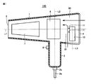
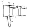
- FIG. 1 is a cross-sectional view of hair dryer 100 according to Embodiment 1 of the present invention.
- FIG. 2 is a rear view of the hair dryer 100 shown in FIG.
- the hair dryer 100 includes a housing 1, a fan 6, a heater 7, and an ion generator 10.
- the shape of the housing 1 is, for example, a cylindrical shape.
- a suction port 4 is formed on one end surface of the housing 1.
- An air outlet 5 is formed on the other end surface of the housing 1.
- An air flow path 90 extending from the suction port 4 to the blowout port 5 is formed in the housing 1.
- inhalation of a foreign material is provided in the suction inlet 4 side of the hair dryer 100, in FIG. 2, it is not shown for simplification of drawing.
- the fan 6 is rotationally driven by a motor (not shown). As a result, the fan 6 generates an air flow in the air flow path 90.
- the arrow in FIG. 1 represents the direction of airflow.
- the heater 7 is disposed between the fan 6 and the outlet 5. The heater 7 heats the airflow generated by the fan 6.
- the ion generator 10 is disposed between the suction port 4 and the fan 6. The ion generator 10 generates ions by corona discharge.
- a handle 2 is formed in the housing 1 along a direction L2 that intersects the direction L1 of the air flow path 90.
- the handle 2 is hollow.
- a power cord 2a, a bushing 2b for protecting the power cord 2a, and a changeover switch 8 are attached to the handle 2.
- the changeover switch 81 When the user operates the changeover switch 81, the power on / off, hot air / cold air, or generation / non-occurrence of ions is switched.
- FIG. 3 is an external perspective view of the ion generator 10 shown in FIG.
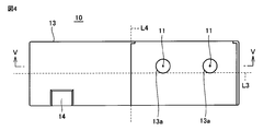
- FIG. 4 is a front view of the ion generator 10 shown in FIG.
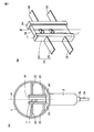
- FIG. 5 is a cross-sectional view of the ion generator 10 taken along the line VV in FIG.
- the ion generator 10 includes a case 13 and a connection terminal 14.
- the case 13 houses the discharge electrode 11, the induction electrode 12, the substrate 15, and a circuit board (not shown).
- a voltage generation circuit (not shown) is mounted on the circuit board.
- the case 13 has a substantially rectangular parallelepiped shape, for example, and has a longitudinal direction L3 and a lateral direction L4. Electric power is supplied to the hair dryer 100 via the power cord 2a.
- the connection terminal 14 receives the supplied power.
- the voltage generation circuit generates a voltage for causing corona discharge.
- the discharge electrode 11 is a needle-like electrode formed on the surface along the longitudinal direction L3.
- the induction electrode 12 is a plate-like electrode provided with a through hole.
- the discharge electrode 11 and the induction electrode 12 are disposed on the substrate 15 so as to face each other.
- a voltage generated by a voltage generation circuit is applied between the discharge electrode 11 and the induction electrode 12.
- corona discharge occurs. Ions are generated by this corona discharge.
- the generated ions are discharged to the outside of the ion generator 10 from the discharge hole 13a.
- the ion generator 10 can also generate ions of either polarity.
- the ion generator 10 has two pairs of discharge electrodes 11 and induction electrodes 12. These two pairs of electrodes (discharge electrode 11 and induction electrode 12) generate positive ions and negative ions, respectively. Thereby, in this Embodiment, the ion generation part 10 produces
- the two pairs of electrodes are arranged along the longitudinal direction L3. However, the arrangement of the two pairs of electrodes is not limited to this. The two pairs of electrodes may be arranged, for example, along the short direction L4. Further, the number of electrodes is not particularly limited.
- a positive ion is a cluster ion in which a plurality of water molecules are attached around a hydrogen ion (H + ).
- the positive ions are represented as H + (H 2 O) m (m is a natural number).
- a negative ion is a cluster ion in which a plurality of water molecules are attached around an oxygen ion (O 2 ⁇ ).
- Negative ions are represented as O 2 ⁇ (H 2 O) n (n is a natural number).
- Positive ions and negative ions generated in the ion generation unit 10 are carried to the air flow path 90 by riding on an ion stream. The ion airflow containing positive ions and negative ions merges with the airflow flowing through the air flow path 90.
- discharge electrode is not limited to the needle-like discharge electrode 11 described above, and may be a creeping discharge electrode formed on the surface of the ion generator 10, for example.
- the “discharge electrode” according to the present invention may generate other ions.
- the ion generator 10 is arranged in the housing 1 in the vicinity of the suction port 4 so that the longitudinal direction L3 intersects the air flow path direction L1.
- the suction port 4 is also formed on the lower side (the side on which the handle 2 is provided) of the ion generator 10 in the longitudinal direction L3.
- the ion flow path 91 is formed along the longitudinal direction L3 from one end of the surface where an electrode is formed to the other end.
- the ion channel 91 is formed along a direction L3 that intersects the direction L1 of the air channel 90 and is along the surface on which the electrodes are formed.
- an electrode is formed in the downstream with respect to the ion generation part 10 of the air flow path 90
- the surface in which an electrode is formed is not limited to this.
- the electrode may be formed on the upstream side of the air flow channel 90 with respect to the ion generation unit 10.
- the electrode may be formed on a plane parallel to a plane including a direction L1 of the air flow path 90 and a direction L2 intersecting the direction L1 of the air flow path 90 (a plane parallel to the paper surface). In this case, the location where the ion channel is formed is changed according to the surface on which the electrode is formed.
- the area of the suction port is larger than the area of the air outlet in order to increase the speed of the air blown from the air outlet (wind speed).
- the length between the wall surfaces of the air flow path 90 in the direction L2 that intersects the direction L1 of the air flow path 90 increases as the distance from the blowout port 5 to the suction port 4 increases. For this reason, a relatively large space exists in the vicinity of the suction port 4. Therefore, the vicinity of the suction port 4 is suitable for disposing the ion generator 10 so that the longitudinal direction L3 intersects the direction L1 of the air flow path 90. 1 and 2, the direction L2 that intersects the direction L1 of the air flow path 90 is included in the paper surface.
- the direction L2 that intersects the direction L1 of the air flow path 90 is not limited to the page, and may be, for example, a direction perpendicular to the page.
- the ion generation unit 10 By arranging the ion generation unit 10 in this way, the length of the casing 1 along the direction L1 of the air flow path 90 can be shortened. That is, the hair dryer can be reduced in size with respect to the direction of the air flow path.
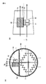
- FIG. 6 is a diagram schematically showing a structure for fixing the ion generator 10 shown in FIG. 5 to the housing 1.
- FIG. 6 (A) shows a case where ion generator 10 is relatively thick (when the thickness between the surface where discharge hole 13 a is formed and the opposite surface is large).
- the structure for fixing the ion generation part 10 is represented.
- FIG. 6B shows that the ion generator 10 is fixed when the ion generator 10 is relatively thin (when the thickness between the surface where the discharge hole 13a is formed and the opposite surface is small). Represents a structure for.
- ion generator 10 when case 13 is relatively thick, ion generator 10 is fixed to housing 1 by, for example, an L-shaped fixture 20.
- One end of the fixing bracket 20 is fixed to the side surface of the case 13 (surfaces on both sides of the surface on which the discharge hole 13 a is formed) with screws 22.
- the other end of the fixing bracket 20 is fixed to the housing 1.
- ion generator 10 is fixed to housing 1 by, for example, a plate-shaped fixture 21.
- a fixing bracket 21 is fixed to the back surface of the case 13 (the surface opposite to the surface on which the discharge holes 13 a are formed) with screws 22. Both ends (not shown) of the fixing bracket 21 are fixed to the housing 1.
- FIG. 7 is a diagram schematically showing a structure for fixing ion generating unit 10 different from the structure shown in FIG. With reference to FIG. 7, FIG. 7A is a rear view of the hair dryer 100. FIG. 7B shows the structure of the fixture 23 for fixing the ion generator 10.
- the fixing bracket 23 has an accommodating part 24 and a plate-like part 25.
- the accommodating part 24 has a substantially rectangular parallelepiped shape.
- An opening surface for fitting the ion generation unit 10 is formed on one surface of the storage unit 24.
- the ion generator 10 is sandwiched from both sides by a pair of accommodating parts 24.
- a gap is provided between the pair of accommodating portions 24 along the longitudinal direction L3 so that air flows along the discharge hole 13a.
- One end of the plate-like portion 25 is fixed to a surface opposite to the opening surface of the accommodating portion 24. From that surface, the plate-like portion 25 extends to the side opposite to the opening surface. The other end of the plate-like portion 25 is fixed to the housing 1.
- the ion generation unit 10 can be fixed to the housing 1 using the structure described in FIG. 6 or FIG.
- the structure for fixing the ion generator 10 to the housing 1 is not particularly limited to the structure shown in FIG. 6 or FIG.
- FIG. 8 is a cross-sectional view of hair dryer 101 according to a modification of Embodiment 1 of the present invention.
- hair dryer 101 is provided with a rib (projection) 1 a on the downstream side of air flow channel 90 with respect to ion generation unit 10.
- the rib 1a protrudes from the wall surface of the air flow path 90 along the longitudinal direction L3 of the ion generation unit 10.
- the rib 1a guides the air that is sucked from the suction port 4 and goes around the ion generation unit 10 to the electrode in the direction L2 that intersects the direction of the air flow path 90. Thereby, more ions get on the airflow flowing through the air flow path 90. Therefore, according to the present modification, the amount of ions (number of ions per unit volume) blown out from the blowout port 5 can be increased as compared with the first embodiment. Since the other structure of the hair dryer 101 is equivalent to the structure of the hair dryer 100 (see FIG. 1), detailed description will not be repeated.
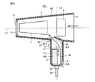
- FIG. 9 is a cross-sectional view of hair dryer 200 according to Embodiment 2 of the present invention.
- handle 2 is arranged between fan 6 and suction port 4 along direction L ⁇ b> 1 of air flow path 90.
- the ion generator 10 is disposed in the handle 2.
- the handle 2 is formed in the housing 1 along the direction L2 that intersects the direction L1 of the air flow path 90. That is, the ion generator 10 is disposed in the handle 2 so that the longitudinal direction L3 of the ion generator 10 coincides with the intersecting direction L2.
- the handle 2 is formed with an inlet 914, an outlet 915, and an ion channel 91 extending from the inlet 914 to the outlet 915.
- the suction port 914 is formed farther from the electrode than the connection portion 2c between the housing 1 and the handle 2 along the direction L2 intersecting the direction L1 of the air flow path 90.
- the blower outlet 915 is formed in the connection part 2c. Since the other structure of the hair dryer 200 is equivalent to the structure of the hair dryer 100 (see FIG. 1), detailed description will not be repeated.
- the casing can be further reduced in size with respect to the direction of the air flow path as compared with the first embodiment.
- the ion generation unit does not block the airflow flowing through the air flow path, the amount of air blown from the blowout port 5 (air flow rate) can be increased.
- FIG. 10 is a cross-sectional view of a hair dryer 201 according to a modification of the second embodiment of the present invention.
- the handle 2 is disposed between the fan 6 and the outlet 5 along the direction L ⁇ b> 1 of the air flow path 90. Since the other structure of the hair dryer 201 is equivalent to the structure of the hair dryer 200 (see FIG. 9), detailed description will not be repeated.
- the housing 1 is provided with a rib 1b.
- the rib 1b partially closes the air outlet 915 of the ion channel 91.
- the area B of the blower outlet 915 of the ion flow path 91 becomes smaller than the area A of the suction inlet 914 of the ion flow path 91 (B ⁇ A).
- the area B of the air outlet 915 of the ion channel 91 is smaller than the area C of the air outlet 5 of the air channel 90 (B ⁇ C). That is, an “orifice structure” is realized in the flow path from the suction port 914 through the ion flow path 91 to the air outlet 5 of the air flow path 90.
- a portion where the air outlet 915 of the ion channel 91 is formed is an “orifice”.
- the pressure on the downstream side of the orifice becomes lower (the negative pressure) than the pressure on the upstream side of the orifice.
- the pressure downstream of the suction port 914 is upstream of the suction port 914 of the ion flow channel 91. Lower than the pressure on the side. For this reason, the ion airflow which flows into the suction inlet 914-ion flow path 91-blower outlet 915-blower outlet 5 can be produced. As a result, ions generated by the ion generator 10 provided in the handle 2 can be guided to the air flow path 90.
- the housing 1 having the air inlet 90 and the air outlet 5 and having the air flow path 90 extending from the air inlet 4 to the air outlet 5, and the fan 6 disposed in the air flow path 90 and generating an air flow
- the heater 7 is disposed in the air flow path 90 and heats the air flowing through the air flow path 90, and has a longitudinal direction L3 and a short direction L4.
- the longitudinal direction L3 intersects the direction L1 of the air flow path 90.
- the ion generator 10 has a discharge electrode 11 for generating ions on a surface along the longitudinal direction L3, and the housing 1 has an air flow path 90.
- the hair dryers 100, 101, 200, and 201 further include an ion channel 91 that is formed along a direction L3 that intersects the direction L1 and that extends along the surface on which the electrode is formed.
- the casing 1 further includes a rib 1a that protrudes along the longitudinal direction L3 of the ion generation unit 10 from the wall surface of the air flow channel 90 on the downstream side of the air flow channel 90 with respect to the ion generation unit 10. 101.
- the housing 1 further includes a handle 2 that is connected to the housing 1 along a direction L2 that intersects the direction L1 of the air flow path 90, and in which an ion flow path 91 is formed.
- the longitudinal direction L3 of the ion generating part 10 is disposed in the handle 2 so as to coincide with the intersecting direction L2, and the handle 2 is connected to the casing 1 and the handle 2 along the intersecting direction L2.
- a hair dryer 200 having a suction port 914 of the ion channel 91 formed far from the discharge electrode 11 and the induction electrode 12 and a blowout port 915 of the ion channel 91 formed in the connecting portion 2c. 201.
- the housing can be reduced in size. Moreover, since the ion generating part does not block the airflow in the air flow path, the air volume increases. Furthermore, since the position of the center of gravity of the hair dryer is close to the handle, the sense of stability when the handle is held is improved.
- the handle 2 is disposed between the fan 6 and the air outlet 5 of the air flow path 90 along the direction L1 of the air flow path 90, and the area A of the suction port 914 of the ion flow path 91 is defined as ion
- the hair dryer 201 which is larger than the area B of the air outlet 915 of the flow path 91, and has an area C of the air outlet 5 of the air flow path 90 larger than the area B of the air outlet 915 of the ion flow path 91.
- FIG. 11 is a cross-sectional view of hair dryer 300 according to Embodiment 3 of the present invention.
- hair dryer 300 includes housing 1, fan 6, heater 7, and ion generator 30.
- the shape of the housing 1 is, for example, a cylindrical shape.
- a suction port 4 is formed on one end surface of the housing 1.
- An air outlet 5 is formed on the other end surface of the housing 1.
- An air flow path 90 extending from the suction port 4 to the blowout port 5 is formed in the housing 1.
- the ion flow path 91 from the suction inlet 914 to the blower outlet 915 is formed in the housing
- FIG. The ion channel 91 and the air channel 90 are separated by the partition wall 1c.
- the fan 6 and the heater 7 are accommodated in the air flow path 90.
- the fan 6 is rotationally driven by a motor (not shown). As a result, the fan 6 generates an air flow in the air flow path 90.
- the arrow in FIG. 11 represents the direction of airflow.
- the heater 7 is disposed between the fan 6 and the outlet 5. The heater 7 heats the air flowing through the air flow path 90 generated by the fan 6.
- a handle 2 for the user to hold the hair dryer 100 is formed on the suction port 4 side of the housing 1.
- a changeover switch 81 and a power switch 82 are attached to the handle 2. When the user operates the changeover switch 81, hot air / cold air and generation / non-occurrence of ions are switched. Further, when the user operates the power switch 82, the power is turned on / off.
- the ion generating part 30 is accommodated in the ion channel 91.
- the ion generator 30 includes a needle-shaped discharge electrode 31, an annular counter electrode 32, a Peltier element 33, and a heat sink 34.
- the ion generator 30 generates negative ions.
- FIG. 12 is a cross-sectional view of the hair dryer 300 shown in FIG.
- FIG. 12A is a cross-sectional view of the hair dryer 300 taken along line XIIA-XIIA in FIG.
- FIG. 12B is a cross-sectional view of the hair dryer 300 along the line XIIB-XIIB in FIG.
- discharge electrode 31 and counter electrode 32 are arranged to face each other.
- the Peltier element 33 cools the discharge electrode 31. Thereby, water in the air condenses on the discharge electrode 31.
- a negative voltage generated by a voltage generation circuit (not shown) is applied to the discharge electrode 11, a discharge is generated between the discharge electrode 31 and the counter electrode 32. During this discharge, water condensed on the discharge electrode 31 undergoes Rayleigh splitting and becomes negative ions (negatively charged fine particle water).
- the heat sink 34 is provided to dissipate heat from the Peltier element 33.
- the heat sink 34 includes a heat radiating plate 35 and a plurality of fins 36.
- a Peltier element 33 is disposed on the heat radiating plate 35.
- the plurality of fins 36 are formed in parallel to each other in a direction substantially perpendicular to the heat radiating plate 35.
- the heat radiating plate 35 is substantially parallel to the direction L5 of the ion channel 91 (the direction perpendicular to the paper surface in FIG. 12A), and each of the plurality of fins 36 is the ion channel 91. It arrange
- FIG. 13 is a diagram for explaining a conventional arrangement of the ion generator 30.
- the heat sink 34 has been arranged in a direction in which the heat radiating plate 35 is substantially perpendicular to the direction L5 of the ion channel 91 (see Patent Document 2). For this reason, the airflow flowing through the ion channel 91 strikes the heat sink 35 substantially perpendicularly. Therefore, the air heated by the heat to be dissipated stays in the vicinity of the heat radiating plate 35.
- the heat exchange efficiency in the heat sink 34 improves compared with the conventional arrangement (see FIG. 13). That is, even if the heat sink 34 is downsized, the heat exchange efficiency comparable to the conventional arrangement can be obtained.
- the volume ratio of the heat sink to the ion generating portion is large. Therefore, reducing the size of the heat sink 34 is effective in reducing the cross-sectional area of the ion channel 91 (the cross-sectional area in the direction perpendicular to the direction L5 of the ion channel 91).
- the housing 1 can be downsized as a result.
- the cooling effect of the Peltier element 33 is increased by improving the heat exchange efficiency in the heat sink 34. Therefore, since the amount of water condensed on the discharge electrode 31 increases, the amount of negative ions generated can be increased.
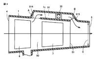
- FIG. 14 is a view for explaining the structure of the air channel 90 and the ion channel 91 shown in FIG.
- the area A of the suction port 914 of the ion channel 91 is larger than the area B of the outlet 915 of the ion channel 91 (B ⁇ A).
- the area C of the blower outlet 5 of the air flow path 90 is larger than the area B of the blower outlet 915 of the ion flow path 91 (B ⁇ C). That is, an “orifice structure” is realized in the flow path from the suction port 914 through the ion flow path 91 to the air outlet 5 of the air flow path 90.
- a portion where the air outlet 915 of the ion channel 91 is formed is an “orifice”.
- the pressure downstream of the orifice becomes lower (negative pressure) than the pressure upstream of the orifice.
- the pressure downstream of the suction port 914 in the direction of the flow path from the suction port 914 to the blowout port 5 through the ion flow channel 91, the pressure downstream of the suction port 914 is upstream of the suction port 914 of the ion flow channel 91. Lower than the pressure on the side. For this reason, the ion airflow which flows into the suction inlet 914-ion flow path 91-blower outlet 915-blower outlet 5 can be produced.
- the user adjusts the direction of the outlet of the hair dryer according to the sensation of warm air flowing through the air flow path hitting the hair. For this reason, when the direction of the airflow which flows through an air flow path and the direction of an ion airflow differ, it is thought that the quantity of the negative ion which directly hits a user's hair becomes small.
- the ion air current blown out from the air outlet 915 of the ion flow path 91 merges with the air flow flowing through the air flow path 90. For this reason, negative ions are blown out from the outlet 5 together with the airflow flowing through the air flow path 90. Therefore, the amount of negative ions that directly hit the hair can be increased. As a result, the hair moisturizing effect or static electricity suppressing effect can be improved. Moreover, since the speed of the airflow which flows through the air flow path 90 is significantly larger than the speed of the ion airflow, the reach distance of negative ions can also be extended.
- the filter 51 is provided to prevent the user from coming into contact with the heater 7.
- the filter 51 includes a material that can be charged by negative ions generated by the ion generator 30.
- the filter 51 is, for example, a metal lattice.
- the ion airflow containing negative ions merges with the airflow flowing through the air flow path 90 on the downstream side of the filter 51. Accordingly, since negative ions are difficult to adhere to the filter 51, charging of the filter 51 is suppressed. Therefore, it is possible to suppress a decrease in the amount of negative ions blown out from the outlet 5.
- FIG. 15 is a cross-sectional view of a hair dryer 301 according to a modification of the third embodiment of the present invention.
- FIG. 16 is an external perspective view of the nozzle 83 shown in FIG.
- FIG. 17 is a diagram for explaining the structure of the nozzle 83 shown in FIG. 16 in detail.
- FIG. 17A is a front view of the nozzle 83 shown in FIG.
- FIG. 17B is a cross-sectional view of the nozzle 83 along the line XVIIB-XVIIB in FIG.
- hair dryer 301 is provided with nozzle 83, and is provided with ion generator 30a instead of ion generator 30 (see FIG. 12). ) Is different.
- the nozzle 83 is detachable from the housing 1.
- FIG. 15 shows a state in which the nozzle 83 is attached to the housing 1.
- the cross-sectional shape of the nozzle 83 between the side that receives the airflow and the side that blows out the airflow when mounted on the housing 1 is curved.
- the nozzle 83 causes the airflow flowing through the air flow path 90 and the ion airflow to merge.
- the nozzle 83 has a large area on the side that receives the airflow when mounted on the housing 1 and a small area on the side that blows out the airflow. For this reason, by attaching the nozzle 83, the speed of the airflow blown out from the hair dryer can be increased. On the other hand, the hair dryer can be downsized by removing the nozzle 83.
- FIG. 18 is a diagram for explaining the structure of an ion generator 30a having a structure different from that of the ion generator 30 shown in FIG.
- ion generation unit 30 a includes ion generation unit 30 (see FIG. 12) in that it includes discharge electrode 31 a instead of discharge electrode 31, and includes counter electrode 32 a instead of counter electrode 32. And different.
- the shape of the discharge electrode 31a is L-shaped.
- the direction in which the needle tip of the discharge electrode 31a faces coincides with the direction L5 of the ion channel 91.
- the annular counter electrode 32a is disposed so as to surround the needle tip of the discharge electrode 31a. With this arrangement, an ion stream flows through the counter electrode 32a. Since the other structure of the hair dryer 301 is equivalent to the structure of the hair dryer 300 (see FIG. 11), detailed description will not be repeated.
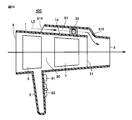
- FIG. 19 is a cross-sectional view of hair dryer 400 according to Embodiment 4 of the present invention.
- FIG. 20 is a diagram for explaining the structure of the air channel 90 and the ion channel 91 shown in FIG.
- the structure of the hair dryer 400 is that the suction port 914 of the ion channel 91 is formed independently from the suction port 4 of the air channel 90. Different from the structure of
- the area A of the inlet 914 of the ion channel 91 is larger than the area B of the outlet 915 of the ion channel 91 (B ⁇ A).
- the area C of the air outlet 5 of the air channel 90 is larger than the area B of the air outlet 915 of the ion channel 91 (B ⁇ C). That is, an “orifice structure” is realized in the path from the suction port 914 to the outlet 5 of the air channel 90 through the ion channel 91. Therefore, it is possible to generate an ion airflow that flows in the suction port 914 -the ion channel 91 -the outlet 915 -the outlet 5. Since the other structure of the hair dryer 400 is equivalent to the structure of the hair dryer 300, detailed description will not be repeated.
- FIG. 21 is a cross-sectional view of a hair dryer 401 according to a modification of the fourth embodiment of the present invention.
- the air outlet 5 of the air flow path 90 of the hair dryer 401 is formed by a nozzle 83 that can be attached to and detached from the housing 1. By mounting the nozzle 83, the speed of the airflow blown out from the hair dryer can be increased. Since the other structure of the hair dryer 401 is equivalent to the structure of the hair dryer 400 (see FIG. 19), detailed description will not be repeated.
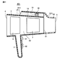
- FIG. 22 is a cross-sectional view of hair dryer 500 according to Embodiment 5 of the present invention.
- hair dryer 500 has a structure in which suction port 914 of ion channel 91 is formed by branching from suction port 4 of air channel 90. The structure is different.
- the area A of the inlet 914 of the ion channel 91 is larger than the area B of the outlet 915 of the ion channel 91 (B ⁇ A).
- the area C of the air outlet 5 of the air channel 90 is larger than the area B of the air outlet 915 of the ion channel 91 (B ⁇ C). That is, an “orifice structure” is realized in the path from the suction port 914 to the outlet 5 of the air channel 90 through the ion channel 91. Therefore, it is possible to generate an ion airflow that flows in the suction port 914 -the ion channel 91 -the outlet 915 -the outlet 5. Since the other structure of hair dryer 500 is equivalent to the structure of hair dryer 300 (see FIG. 11), detailed description will not be repeated.
- FIG. 23 is a cross-sectional view of a hair dryer according to a modification of Embodiment 5 of the present invention.
- the air outlet 5 of the air flow path 90 of the hair dryer 501 is formed by a nozzle 83 that can be attached to and detached from the housing 1. By mounting the nozzle 83, the speed of the airflow blown out from the hair dryer can be increased. Since the other structure of the hair dryer 501 is equivalent to the structure of the hair dryer 500 (see FIG. 22), detailed description will not be repeated.
- FIG. 24 is an external perspective view of a nozzle having a shape different from that in FIG.
- FIG. 25 is a diagram for explaining the structure of the nozzle 84 shown in FIG. 24 in detail.
- FIG. 25A is a front view of the nozzle 84 shown in FIG.
- FIG. 25B is a cross-sectional view of the nozzle 84 taken along line XXVB-XXVB in FIG.
- the structure of the nozzle 84 is that the nozzle 84 is linear in the cross-sectional shape between the side that receives the airflow and the side that blows out the airflow when mounted on the housing 1. This is different from the structure 83 (see FIGS. 16 and 17). Since the other structure of nozzle 84 is equivalent to the structure of nozzle 83, detailed description will not be repeated.
- the hair dryers 301, 401, and 501 may include a nozzle 84 instead of the nozzle 83.
- the housing 1 having the air flow path 90 extending from the suction port 4 to the air outlet 5 and the ion flow path 91 different from the air flow path 90, in which the air inlet 4 and the air outlet 5 are formed, and the air flow Ion disposed in the channel 90 and generating air current, the heater 7 for heating the air flowing in the air channel 90, and the ion channel 91, and generating the negative ions
- the generators 30 and 30a include discharge electrodes 31 and 31a and counter electrodes 32 and 32a that generate negative ions, a Peltier element 33 that cools the discharge electrodes 31 and 31a, and a Peltier element.
- a heat sink 34 for dissipating heat from the heat sink 33.
- the heat sink 34 is a heat sink 35 on which the Peltier element 33 is disposed, and a plurality of heat sinks 34 formed in parallel to each other in a direction substantially perpendicular to the heat sink 35.
- the heat sink 34 has a heat dissipation plate 35 that is substantially parallel to the direction L5 of the ion flow path 91, and each of the plurality of fins 36 is directed to the direction L5 of the ion flow path 91.
- a filter 51 made of a material that can be charged is further provided between the heater 7 and the outlet 5, and the ion channel 91 is configured such that the air blown from the ion channel 91 is directed toward the air channel 90.
- a hair dryer 300, 301, 400, 401, 500, 501 is formed so as to merge with the air flow path 90 on the outlet 5 side of the filter 51.
- negative ions are blown out from the outlet 5 together with the airflow flowing through the air flow path 90. Therefore, even if the user is not particularly conscious of applying negative ions to the hair, the amount of negative ions directly hitting the hair is large. As a result, the hair moisturizing effect or static electricity suppressing effect can be improved. In addition, the reach of negative ions can be extended. Furthermore, since negative ions are unlikely to adhere to the filter 51, charging of the filter 51 is suppressed. Therefore, it is possible to suppress a decrease in the amount of negative ions blown out from the outlet 5.
- the air outlet 90 of the air flow path 90 is a hair dryer 301, 401, 501 formed by nozzles 83, 84 that can be attached to and detached from the housing 1.
- the speed of the airflow blown from the hair dryer can be increased by mounting the nozzle.
- a hair dryer can be reduced in size by removing a nozzle.
- the suction port 914 of the ion channel 91 is provided independently of the air channel 90, and the area A of the suction port 914 of the ion channel 91 is larger than the area B of the outlet 915 of the ion channel 91.
- the hair dryers 400 and 401 are large, and the area C of the air outlet 5 of the air channel 90 is larger than the area B of the air outlet 915 of the ion channel 91.
- the ion channel 91 is formed by branching from the air channel 90, and the area A of the suction port 914 of the ion channel 91 is larger than the area B of the outlet 915 of the ion channel 91,
- the hair dryers 300, 301, 500, and 501 have an area C of the air outlet 5 of the channel 90 that is larger than an area B of the air outlet 915 of the ion channel 91.
Landscapes
- Cleaning And Drying Hair (AREA)
Abstract
ヘアードライヤー(100)は、筐体(1)と、ファン(6)と、ヒータ(7)と、イオン発生部(10)とを備える。筐体(1)は、吸込口(4)および吹出口(5)が形成され、吸込口(4)から吹出口(5)へと至る空気流路(90)を有する。ファン(6)は、空気流路(90)に配置され、気流を生じさせる。ヒータ(7)は、空気流路(90)に配置され、空気流路(90)を流れる空気を加熱する。イオン発生部(10)は、長手方向(L3)が空気流路の方向(L1)と交差するように配置される。イオン発生部(10)は、長手方向(L3)に沿った面に、イオンを発生させるための放電電極(11)を有する。筐体(1)は、空気流路の方向(L1)と交差し、かつ放電電極(11)が形成される面に沿う方向(L3)に沿って形成されたイオン流路(91)をさらに有する。
Description
本発明は、ヘアードライヤーに関し、特に、イオン発生部を備えるヘアードライヤーに関する。
イオンを毛髪に当てることによって、毛髪の保湿効果または静電気抑制効果などを得られることが実証されている。このような効果を得るために、イオン発生部を備えるヘアードライヤーが提案されている。
たとえば実開平6―21506号公報(特許文献1)に開示されたヘアードライヤーには、モーターファン部とヒータ部とが内装される。モーターファン部とヒータ部との間に、トランスの一次側巻線側に直列共振回路が接続される。トランスの二次側巻線端子にイオン電極とオゾン電極とが接続される。直列共振回路に通電してイオン電極間とオゾン電極間とに高電圧を出力することにより、マイナスイオンとオゾンとを発生させる。
また、特開2002―191426号公報(特許文献2)に開示されたヘアードライヤーでは、ハウジングの内部に空気流路が形成される。その空気流路内にファンとヒータとが配置される。空気流路の下流側端部に、空気を吐出する空気吐出口が設けられる。ハウジングには、空気流路とは別のイオン流路が設けられるとともに、そのイオン流路にマイナスイオンを発生可能なイオン発生部が設けられる。イオン流路の下流側端部に、マイナスイオンを吐出するイオン吐出口が設けられる。
特開2008―29813号公報(特許文献3)に開示された加熱送風装置では、吸入口から吐出口に至る空気流路内に、回転駆動されるファンおよび加熱手段が配置される。また、空気流路から分岐してイオン吹出口に至る流路中に、放電電極と対向電極とを備えるイオン発生手段が配置される。イオン吹出口に、イオンを通過させるための開口を備えたカバーが配置される。カバーは、イオン吹出口よりも前方に位置する吐出口の外周も覆う。カバーの背面に一体に設けられた突部が、イオン発生手段の対向電極よりもカバー側に位置する対向電極に接触する。これにより、カバーが対向電極を介して接地される。
ヘアードライヤーの取扱いまたは持運びを容易にするためには、ヘアードライヤーは小型であることが好ましい。しかしながら、イオン発生部を備えることによって、ヘアードライヤーが大型化する可能性がある。このように、使用者の利便性の点において、イオン発生部を備えるヘアードライヤーは課題を有し得る。
本発明の目的は、イオン発生部を備えるヘアードライヤーを小型化するための技術を提供することである。
本発明のある局面に係るヘアードライヤーは、筐体と、ファンと、ヒータと、イオン発生部とを備える。筐体は、吸込口および吹出口が形成され、吸込口から吹出口へと至る空気流路を有する。ファンは、空気流路に配置され、気流を生じさせる。ヒータは、空気流路に配置され、空気流路を流れる空気を加熱する。イオン発生部は、長手方向と短手方向とを有し、長手方向が空気流路の方向と交差するように配置される。イオン発生部は、長手方向に沿った面に、イオンを発生させるための電極を有する。筐体はイオン流路をさらに有する。イオン流路は、空気流路の方向と交差し、かつ電極が形成される面に沿う方向に沿って形成される。
好ましくは、空気流路の方向と交差する上記方向についての空気流路の壁面間の長さは、吹出口から吸込口に近くなるに従って大きくなる。イオン発生部は、空気流路の方向に沿って、ファンと吸込口との間で筐体内に配置される。
好ましくは、筐体は突起部をさらに有する。突起部は、空気流路のイオン発生部に対する下流側に、空気流路の壁面からイオン発生部の長手方向に沿って突出する。
好ましくは、筐体は、ハンドルをさらに有する。ハンドルは、空気流路の方向と交差する方向に沿って筐体に連結され、イオン流路が形成される。イオン発生部は、イオン発生部の長手方向が、交差する方向と一致するようにハンドル内に配置される。ハンドルは、イオン流路の吸込口と、イオン流路の吹出口とを有する。イオン流路の吸込口は、交差する方向に沿って、筐体とハンドルとの連結部から電極よりも遠くに形成される。イオン流路の吹出口は、連結部に形成される。
好ましくは、ハンドルは、空気流路の方向に沿って、ファンと空気流路の吹出口との間に配置される。イオン流路の吸込口の面積は、イオン流路の吹出口の面積よりも大きい。空気流路の吹出口の面積は、イオン流路の吹出口の面積よりも大きい。
本発明によれば、イオン発生部を備えるヘアードライヤーを小型化することができる。
以下、本発明の実施の形態について図面を参照しながら詳細に説明する。なお、図中同一または相当部分には同一符号を付して、その説明を繰り返さない。
[実施の形態1]
図1は、本発明の実施の形態1に係るヘアードライヤー100の断面図である。図2は、図1に示したヘアードライヤー100の背面図である。
図1は、本発明の実施の形態1に係るヘアードライヤー100の断面図である。図2は、図1に示したヘアードライヤー100の背面図である。
図1および図2を参照して、ヘアードライヤー100は、筐体1と、ファン6と、ヒータ7と、イオン発生部10とを備える。筐体1の形状は、たとえば筒状である。筐体1の一方の端面には吸込口4が形成される。筐体1の他方の端面には吹出口5が形成される。筐体1には、吸込口4から吹出口5へと至る空気流路90が形成される。空気流路90内に、ファン6と、ヒータ7と、イオン発生部10とが収容される。なお、ヘアードライヤー100の吸込口4側には、異物の吸込みを防ぐためのフィルタが設けられるが、図2では図面の簡略化のために示されていない。
ファン6は、モータ(図示せず)によって回転駆動される。これによりファン6は、空気流路90内に気流を生じさせる。図1中の矢印が気流の方向を表す。ヒータ7は、ファン6と吹出口5との間に配置される。ヒータ7は、ファン6が生じさせた気流を加熱する。イオン発生部10は、吸込口4とファン6との間に配置される。イオン発生部10は、コロナ放電によってイオンを発生させる。
筐体1には、空気流路90の方向L1と交差する方向L2に沿って、ハンドル2が形成される。ハンドル2は中空である。ハンドル2には、電源コード2aと、電源コード2aを保護するためのブッシング2bと、切替スイッチ8とが取り付けられる。使用者が切替スイッチ81を操作することによって、電源のオン/オフ、温風/冷風、またはイオンの発生/不発生が切り替えられる。
図3は、図1に示したイオン発生部10の外観斜視図である。図4は、図1に示したイオン発生部10の正面図である。図5は、図4のV―V線に沿うイオン発生部10の断面図である。
図3~図5を参照して、イオン発生部10は、ケース13と、接続端子14とを備える。ケース13には、放電電極11と、誘導電極12と、基板15と、回路基板(図示せず)とが収容される。回路基板には電圧生成回路(図示せず)が実装される。
ケース13は、たとえば略直方体形状であって、長手方向L3と短手方向L4とを有する。ヘアードライヤー100には、電源コード2aを介して電力が供給される。接続端子14は、供給された電力を受ける。電圧生成回路は、コロナ放電を生じさせるための電圧を生成する。
放電電極11は、長手方向L3に沿った面に形成された針状の電極である。誘導電極12は、貫通穴が設けられた板状の電極である。放電電極11と誘導電極12とは、互いに対向するように基板15に配置される。放電電極11と誘導電極12との間に、電圧生成回路によって生成された電圧が印加される。放電電極11と誘導電極12との間の電界強度が一定以上になると、コロナ放電が生じる。このコロナ放電によってイオンが発生する。発生したイオンは、放出穴13aからイオン発生部10の外部に放出される。
イオン発生部10は、いずれか一方の極性のイオンを発生させることも可能である。しかし、本実施の形態においてイオン発生部10は、2対の放電電極11と誘導電極12とを有する。これら2対の電極(放電電極11および誘導電極12)は、正イオンおよび負イオンをそれぞれ発生させる。これにより、本実施の形態では、イオン発生部10は両極性のイオンを略同等量発生させる。本実施の形態において、2対の電極は長手方向L3に沿って配置される。しかし、2対の電極の配置はこれに限定されるものではない。2対の電極は、たとえば短手方向L4に沿って配置されてもよい。また、電極の数も特に限定されない。
正イオンは、水素イオン(H+)の周囲に複数の水分子が付随したクラスターイオンである。正イオンは、H+(H2O)m(mは自然数)と表される。負イオンは、酸素イオン(O2
-)の周囲に複数の水分子が付随したクラスターイオンである。負イオンは、O2
-(H2O)n(nは自然数)と表される。イオン発生部10で発生した正イオンおよび負イオンは、イオン気流に乗って空気流路90へと運ばれる。正イオンおよび負イオンを含むイオン気流は、空気流路90を流れる気流と合流する。これにより、正イオンおよび負イオンを含む空気が吹出口5から吹き出される。なお、本発明に係る「放電電極」は、上記の針状の放電電極11に限定されるものではなく、たとえばイオン発生部10の表面に形成された沿面の放電電極であってもよい。本発明に係る「放電電極」は、他のイオンを発生させるものであってもよい。
図1および図2に戻り、イオン発生部10は、吸込口4の近傍において、長手方向L3が空気流路の方向L1と交差するように筐体1内に配置される。吸込口4は、イオン発生部10の長手方向L3の下側(ハンドル2が設けられた側)にも形成される。これにより、イオン発生部10に対し、電極が形成される面の一端から他端へと長手方向L3に沿ってイオン流路91が形成される。言い換えると、イオン流路91は、空気流路90の方向L1と交差し、かつ電極が形成される面に沿う方向L3に沿って形成される。
なお、図1では、電極が空気流路90のイオン発生部10に対する下流側に形成されるが、電極が形成される面はこれに限定されるものではない。たとえば電極は、空気流路90のイオン発生部10に対する上流側に形成されてもよい。あるいは、電極は、空気流路90の方向L1と、空気流路90の方向L1と交差する方向L2とを含む面に平行な面(紙面に平行な面)に形成されてもよい。この場合、イオン流路が形成される箇所は、電極が形成される面に応じて変更される。
一般にヘアードライヤーでは、吹出口から吹き出される空気の速さ(風速)を大きくするために、吸込口の面積が吹出口の面積よりも大きい。空気流路90の方向L1と交差する方向L2についての空気流路90の壁面間の長さは、吹出口5から吸込口4に近くなるに従って大きくなる。このため、吸込口4の近傍には、比較的大きなスペースが存在する。したがって、吸込口4の近傍は、長手方向L3が空気流路90の方向L1と交差するようにイオン発生部10を配置するのに適する。なお、図1および図2では、空気流路90の方向L1と交差する方向L2は紙面内に含まれる。しかし、空気流路90の方向L1と交差する方向L2は、紙面内に限定されるものではなく、たとえば紙面に垂直な方向であってもよい。
このようにイオン発生部10を配置することで、空気流路90の方向L1に沿った筐体1の長さを短くすることができる。すなわち、空気流路の方向に関し、ヘアードライヤーを小型化することができる。
図6は、図5に示したイオン発生部10を筐体1に固定するための構造を概略的に示す図である。図6を参照して、図6(A)は、イオン発生部10が比較的厚い場合(放出穴13aが形成された面と、その反対側の面との間の厚みが大きい場合)に、イオン発生部10を固定するための構造を表す。図6(B)は、イオン発生部10が比較的薄い場合(放出穴13aが形成された面と、その反対側の面との間の厚みが小さい場合)に、イオン発生部10を固定するための構造を表す。
図2および図6(A)を参照して、ケース13が比較的厚い場合、イオン発生部10は、たとえばL字型の固定金具20によって筐体1に固定される。ケース13の側面(放出穴13aが形成された面の両側の面)に、固定金具20の一方端がビス22によって固定される。固定金具20の他方端は、筐体1に固定される。
一方、図6(B)を参照して、ケース13が比較的薄い場合、イオン発生部10は、たとえば平板状の固定金具21によって筐体1に固定される。ケース13の背面(放出穴13aが形成された面の反対側の面)に、固定金具21がビス22によって固定される。固定金具21の両端(図示せず)は、筐体1に固定される。
あるいは、固定金具をイオン発生部にビス留めしなくてもよい。図7は、図6に示した構造とは異なる、イオン発生部10を固定するための構造を概略的に示す図である。図7を参照して、図7(A)は、ヘアードライヤー100の背面図である。図7(B)は、イオン発生部10を固定するための固定金具23の構造を表す。
固定金具23は、収容部24と、板状部25とを有する。収容部24は略直方体形状を有する。収容部24の一面には、イオン発生部10をはめ込むための開口面が形成される。イオン発生部10は、1対の収容部24によって両側から挟まれる。1対の収容部24の間には、放出穴13aに沿って空気が流れるように、長手方向L3に沿って隙間が設けられている。板状部25の一方端は、収容部24の開口面と反対側の面に固定される。その面から、板状部25は開口面とは反対側に延在する。板状部25の他方端は筐体1に固定される。
このように、図6または図7で説明した構造を利用して、イオン発生部10を筐体1に固定することができる。しかし、イオン発生部10を筐体1に固定する構造は、図6または図7に示された構造に特に限定されるものではない。
[実施の形態1の変形例]
図8は、本発明の実施の形態1の変形例に係るヘアードライヤー101の断面図である。図8を参照して、ヘアードライヤー101には、空気流路90のイオン発生部10に対する下流側にリブ(突起部)1aが設けられる。リブ1aは、空気流路90の壁面からイオン発生部10の長手方向L3に沿って突出する。
図8は、本発明の実施の形態1の変形例に係るヘアードライヤー101の断面図である。図8を参照して、ヘアードライヤー101には、空気流路90のイオン発生部10に対する下流側にリブ(突起部)1aが設けられる。リブ1aは、空気流路90の壁面からイオン発生部10の長手方向L3に沿って突出する。
リブ1aは、吸込口4から吸い込まれて、イオン発生部10を回り込む空気を、空気流路90の方向と交差する方向L2に電極へと導く。これにより、より多くのイオンが空気流路90を流れる気流に乗る。したがって、本変形例によれば、実施の形態1と比較して、吹出口5から吹き出されるイオンの量(単位体積当たりのイオンの数)を増加させることができる。ヘアードライヤー101の他の構造は、ヘアードライヤー100(図1参照)の構造と同等であるため、詳細な説明を繰り返さない。
[実施の形態2]
図9は、本発明の実施の形態2に係るヘアードライヤー200の断面図である。図9を参照して、本実施の形態においてハンドル2は、空気流路90の方向L1に沿って、ファン6と吸込口4との間に配置される。
図9は、本発明の実施の形態2に係るヘアードライヤー200の断面図である。図9を参照して、本実施の形態においてハンドル2は、空気流路90の方向L1に沿って、ファン6と吸込口4との間に配置される。
ヘアードライヤー200では、イオン発生部10がハンドル2内に配置される。上述のように、ハンドル2は、空気流路90の方向L1と交差する方向L2に沿って、筐体1に形成される。つまり、イオン発生部10は、イオン発生部10の長手方向L3が、交差する方向L2と一致するようにハンドル2内に配置される。
ハンドル2には、吸込口914と、吹出口915と、吸込口914から吹出口915へと至るイオン流路91とが形成される。吸込口914は、空気流路90の方向L1と交差する方向L2に沿って、筐体1とハンドル2との連結部2cから電極よりも遠くに形成される。吹出口915は、連結部2cに形成される。ヘアードライヤー200の他の構造は、ヘアードライヤー100(図1参照)の構造と同等であるため、詳細な説明を繰り返さない。
本実施の形態によれば、実施の形態1と比較して、空気流路の方向に関し、筐体を一層小型化することができる。また、イオン発生部が空気流路を流れる気流を遮らないため、吹出口5から吹き出される空気の量(風量)を増加させることができる。
[実施の形態2の変形例]
図10は、本発明の実施の形態2の変形例に係るヘアードライヤー201の断面図である。図10を参照して、本変形例においてハンドル2は、空気流路90の方向L1に沿って、ファン6と吹出口5との間に配置される。ヘアードライヤー201の他の構造は、ヘアードライヤー200(図9参照)の構造と同等であるため、詳細な説明を繰り返さない。
図10は、本発明の実施の形態2の変形例に係るヘアードライヤー201の断面図である。図10を参照して、本変形例においてハンドル2は、空気流路90の方向L1に沿って、ファン6と吹出口5との間に配置される。ヘアードライヤー201の他の構造は、ヘアードライヤー200(図9参照)の構造と同等であるため、詳細な説明を繰り返さない。
図9のようにハンドル2がファン6よりも上流側に配置された場合、ハンドル2内のイオン気流は、ファン6によって空気流路90に吸い込まれる。しかし、図10では、イオン流路91の吹出口915から吹き出された気流は、ファン6よりも下流側で空気流路90に合流する。この場合、ハンドル2内のイオン気流はファン6によって吸い込まれにくい。
そこで、筐体1にはリブ1bが設けられる。リブ1bは、イオン流路91の吹出口915を部分的に塞ぐ。これにより、イオン流路91の吹出口915の面積Bが、イオン流路91の吸込口914の面積Aよりも小さくなる(B<A)。イオン流路91の吹出口915の面積Bは、空気流路90の吹出口5の面積Cよりも小さい(B<C)。すなわち、吸込口914からイオン流路91を通って空気流路90の吹出口5へと至る流路には、「オリフィス構造」が実現される。イオン流路91の吹出口915が形成された部分が「オリフィス」である。
ハンドルをオリフィス構造とすることで、オリフィスよりも下流側の圧力は、オリフィスよりも上流側の圧力よりも低くなる(負圧になる)。本実施の形態では、吸込口914からイオン流路91を通って吹出口5へと至る流路の方向において、吸込口914よりも下流側の圧力は、イオン流路91の吸込口914の上流側の圧力よりも低くなる。このため、吸込口914―イオン流路91―吹出口915―吹出口5と流れるイオン気流を生じさせることができる。これにより、ハンドル2内に設けられたイオン発生部10で発生したイオンを、空気流路90へと導くことができる。
本発明の実施の形態1,2、および実施の形態1,2の各々の変形例は、以下のように要約することができる。
(1)吸込口4および吹出口5が形成され、吸込口4から吹出口5へと至る空気流路90を有する筐体1と、空気流路90に配置され、気流を生じさせるファン6と、空気流路90に配置され、空気流路90を流れる空気を加熱するヒータ7と、長手方向L3と短手方向L4とを有し、長手方向L3が空気流路90の方向L1と交差するように配置されたイオン発生部10とを備え、イオン発生部10は、長手方向L3に沿った面に、イオンを発生させるための放電電極11を有し、筐体1は、空気流路90の方向L1と交差し、かつ電極が形成される面に沿う方向L3に沿って形成されたイオン流路91をさらに有する、ヘアードライヤー100,101,200,201。
上記(1)の構成によれば、イオン発生部を備えたヘアードライヤーを小型化することができる。
(2)空気流路90の方向L1と交差する方向L2についての空気流路90の壁面間の長さは、吹出口5から吸込口4に近くなるに従って大きくなり、イオン発生部10は、空気流路90の方向L1に沿って、ファン6と吸込口4との間で筐体1内に配置される、ヘアードライヤー100,101。
上記(2)の構成によれば、吸込口の近傍には、比較的大きなスペースが存在する。したがって、イオン発生部の配置が容易になる。
(3)筐体1は、空気流路90のイオン発生部10に対する下流側に、空気流路90の壁面からイオン発生部10の長手方向L3に沿って突出するリブ1aをさらに有する、ヘアードライヤー101。
上記(3)の構成によれば、より多くのイオンが空気流路での気流に乗る。したがって、吹出口から吹き出されるイオンの量を増加させることができる。
(4)筐体1は、空気流路90の方向L1と交差する方向L2に沿って筐体1に連結され、イオン流路91が形成されたハンドル2をさらに有し、イオン発生部10は、イオン発生部10の長手方向L3が、交差する方向L2と一致するようにハンドル2内に配置され、ハンドル2は、交差する方向L2に沿って、筐体1とハンドル2との連結部2cから放電電極11および誘導電極12よりも遠くに形成された、イオン流路91の吸込口914と、連結部2cに形成された、イオン流路91の吹出口915とを有する、ヘアードライヤー200,201。
上記(4)の構成によれば、筐体を小型化することができる。また、イオン発生部が空気流路での気流を遮らないため、風量が増加する。さらに、ヘアードライヤーの重心の位置がハンドルの近くになるため、ハンドルを保持したときの安定感が向上する。
(5)ハンドル2は、空気流路90の方向L1に沿って、ファン6と空気流路90の吹出口5との間に配置され、イオン流路91の吸込口914の面積Aは、イオン流路91の吹出口915の面積Bよりも大きく、空気流路90の吹出口5の面積Cは、イオン流路91の吹出口915の面積Bよりも大きい、ヘアードライヤー201。
上記(5)の構成によれば、イオン流路の吸込口―イオン流路―イオン流路の吹出口―空気流路の吹出口と流れるイオン気流を生じさせることができる。
[実施の形態3]
図11は、本発明の実施の形態3に係るヘアードライヤー300の断面図である。図11を参照して、ヘアードライヤー300は、筐体1と、ファン6と、ヒータ7と、イオン発生部30とを備える。
図11は、本発明の実施の形態3に係るヘアードライヤー300の断面図である。図11を参照して、ヘアードライヤー300は、筐体1と、ファン6と、ヒータ7と、イオン発生部30とを備える。
筐体1の形状は、たとえば筒状である。筐体1の一方の端面には吸込口4が形成される。筐体1の他方の端面には吹出口5が形成される。筐体1には、吸込口4から吹出口5へと至る空気流路90が形成される。また、筐体1には、吸込口914から吹出口915(図14参照)へと至るイオン流路91が形成される。イオン流路91と空気流路90とは、隔壁1cによって隔てられる。
空気流路90内に、ファン6と、ヒータ7とが収容される。ファン6は、モータ(図示せず)によって回転駆動される。これにより、ファン6は、空気流路90内に気流を生じさせる。図11中の矢印が気流の方向を表す。ヒータ7は、ファン6と吹出口5との間に配置される。ヒータ7は、ファン6が生じさせた空気流路90内を流れる空気を加熱する。
筐体1の吸込口4側には、使用者がヘアードライヤー100を保持するためのハンドル2が形成される。ハンドル2には、切替スイッチ81と、電源スイッチ82とが取り付けられる。使用者が切替スイッチ81を操作することによって、温風/冷風、およびイオンの発生/不発生が切り替えられる。また、使用者が電源スイッチ82を操作することによって、電源のオン/オフが切り替えられる。
イオン流路91内にイオン発生部30が収容される。イオン発生部30は、針状の放電電極31と、環状の対向電極32と、ペルチェ素子33と、ヒートシンク34とを含む。本実施の形態において、イオン発生部30は負イオンを発生させる。
図12は、図11に示したヘアードライヤー300の断面図である。図12(A)は、図11のXIIA―XIIA線に沿うヘアードライヤー300の断面図である。図12(B)は、図11のXIIB―XIIB線に沿うヘアードライヤー300の断面図である。
図12(A)および図12(B)を参照して、放電電極31と対向電極32とは、互いに対向するように配置される。ペルチェ素子33は、放電電極31を冷却する。これにより、空気中の水が放電電極31上に結露する。電圧生成回路(図示せず)によって生成された負電圧が放電電極11に印加されると、放電電極31と対向電極32との間で放電が生じる。この放電に際して、放電電極31上に結露した水は、レイリー分裂を起こして負イオン(負に帯電した微細粒子水)となる。
ヒートシンク34は、ペルチェ素子33からの熱を放散させるために設けられる。ヒートシンク34は、放熱板35と、複数のフィン36とを有する。放熱板35にはペルチェ素子33が配置される。複数のフィン36は、放熱板35に略垂直な方向に、互いに平行に形成される。
ヒートシンク34は、放熱板35がイオン流路91の方向L5(図12(A)では紙面に垂直な方向)に対して略平行であって、かつ複数のフィン36の各々がイオン流路91の方向L5に対して略平行となる向きに配置される。
図13は、イオン発生部30の従来の配置を説明するための図である。図13を参照して、従来、ヒートシンク34は、放熱板35がイオン流路91の方向L5に対して略垂直となる向きに配置されていた(特許文献2参照)。このため、イオン流路91を流れる気流が放熱板35に略垂直に当たる。したがって、放散すべき熱によって暖められた空気が放熱板35付近に滞留してしまう。
図12(B)に戻り、本実施の形態によれば、放熱板35またはフィン36によって、イオン流路91を流れる気流が妨げられることを抑制できる。このため、従来の配置(図13参照)よりも、ヒートシンク34での熱交換効率が向上する。すなわち、ヒートシンク34を小型化しても、従来の配置と同程度の熱交換効率を得ることができる。一般に、ヒートシンクがイオン発生部に占める体積の割合は大きい。したがって、ヒートシンク34を小型化することは、イオン流路91の断面積(イオン流路91の方向L5に垂直な方向の断面積)を小さくする点において有効である。イオン流路91の断面積が小さくなると、結果として筐体1を小型化することができる。
また、ヒートシンク34での熱交換効率の向上により、ペルチェ素子33の冷却効果が増大する。したがって、放電電極31に結露する水の量が増加するため、負イオンの発生量を増加させることができる。
図14は、図11に示した空気流路90およびイオン流路91の構造を説明するための図である。図14を参照して、イオン流路91の吸込口914の面積Aは、イオン流路91の吹出口915の面積Bよりも大きい(B<A)。また、空気流路90の吹出口5の面積Cは、イオン流路91の吹出口915の面積Bよりも大きい(B<C)。すなわち、吸込口914からイオン流路91を通って空気流路90の吹出口5へと至る流路には、「オリフィス構造」が実現される。イオン流路91の吹出口915が形成された部分が「オリフィス」である。
筺体をオリフィス構造とすることで、オリフィスよりも下流側の圧力は、オリフィスよりも上流側の圧力よりも低くなる(負圧になる)。本実施の形態では、吸込口914からイオン流路91を通って吹出口5へと至る流路の方向において、吸込口914よりも下流側の圧力は、イオン流路91の吸込口914の上流側の圧力よりも低くなる。このため、吸込口914―イオン流路91―吹出口915―吹出口5と流れるイオン気流を生じさせることができる。
一般に使用者は、空気流路を流れる温風が毛髪に当たる感覚によって、ヘアードライヤーの吹出口の向きを調整する。このため、空気流路を流れる気流の向きとイオン気流の向きとが異なる場合、使用者の毛髪に直接当たる負イオンの量が小さくなると考えられる。
本実施の形態によれば、イオン流路91の吹出口915から吹き出されたイオン気流は、空気流路90を流れる気流と合流する。このため、負イオンは、空気流路90を流れる気流とともに吹出口5から吹き出される。したがって、毛髪に直接当たる負イオンの量を大きくすることができる。その結果、毛髪の保湿効果または静電気抑制効果を向上することができる。また、空気流路90を流れる気流の速さは、イオン気流の速さよりも大幅に大きいため、負イオンの到達距離を伸ばすこともできる。
フィルタ51は、使用者がヒータ7に接触するのを防ぐために設けられる。フィルタ51は、イオン発生部30が発生させた負イオンによって帯電し得る材料を含む。フィルタ51は、たとえば金属製の格子である。
負イオンを含むイオン気流が、空気流路90を流れる気流とフィルタ51よりも上流側で合流する場合、多くの負イオンがフィルタ51に付着する。フィルタ51に負イオンが付着すると、フィルタ51は負に帯電する。負に帯電したフィルタ51と、イオン気流に含まれる負イオンとの間で電気的反発が生じる。このため、イオン気流に含まれる負イオンがフィルタ51を通過しにくくなる。したがって、吹出口5から吹き出される負イオンの量が減少してしまう。
本実施の形態によれば、負イオンを含むイオン気流は、空気流路90を流れる気流とフィルタ51よりも下流側で合流する。したがって、負イオンがフィルタ51に付着しにくいため、フィルタ51の帯電が抑制される。よって、吹出口5から吹き出される負イオンの量の減少を抑制することができる。
[実施の形態3の変形例]
図15は、本発明の実施の形態3の変形例に係るヘアードライヤー301の断面図である。図16は、図15に示したノズル83の外観斜視図である。図17は、図16に示したノズル83の構造を詳細に説明する図である。図17(A)は、図16に示したノズル83の正面図である。図17(B)は、図17(A)のXVIIB―XVIIB線に沿うノズル83の断面図である。
図15は、本発明の実施の形態3の変形例に係るヘアードライヤー301の断面図である。図16は、図15に示したノズル83の外観斜視図である。図17は、図16に示したノズル83の構造を詳細に説明する図である。図17(A)は、図16に示したノズル83の正面図である。図17(B)は、図17(A)のXVIIB―XVIIB線に沿うノズル83の断面図である。
図15~図17を参照して、ヘアードライヤー301は、ノズル83を備える点、およびイオン発生部30(図12参照)に代えてイオン発生部30aを備える点において、ヘアードライヤー300(図11参照)と異なる。
ノズル83は筐体1に着脱可能である。図15では、筐体1にノズル83が装着された状態が示されている。筐体1に装着された場合に気流を受ける側と、気流を吹き出す側との間のノズル83の断面形状は曲線状である。ノズル83によって、空気流路90を流れる気流とイオン気流とが合流する。ノズル83では、筐体1に装着された場合に気流を受ける側の面積が大きく、気流を吹き出す側の面積は小さい。このため、ノズル83を装着することで、ヘアードライヤーから吹き出される気流の速さを増加させることができる。一方、ノズル83を取り外すことで、ヘアードライヤーを小型化することができる。
図18は、図12に示したイオン発生部30とは異なる構造を有するイオン発生部30aの構造を説明するための図である。図18を参照して、イオン発生部30aは、放電電極31に代えて放電電極31aを含む点、および対向電極32に代えて対向電極32aを含む点において、イオン発生部30(図12参照)と異なる。
放電電極31aの形状はL字型である。放電電極31aの針先が向く方向は、イオン流路91の方向L5と一致する。環状の対向電極32aは、放電電極31aの針先を囲むように配置されている。この配置により、対向電極32aをイオン気流が流れる。ヘアードライヤー301の他の構造は、ヘアードライヤー300(図11参照)の構造と同等であるため、詳細な説明を繰り返さない。
[実施の形態4]
図19は、本発明の実施の形態4に係るヘアードライヤー400の断面図である。図20は、図19に示した空気流路90およびイオン流路91の構造を説明するための図である。
図19は、本発明の実施の形態4に係るヘアードライヤー400の断面図である。図20は、図19に示した空気流路90およびイオン流路91の構造を説明するための図である。
図19および図20を参照して、ヘアードライヤー400の構造は、イオン流路91の吸込口914が、空気流路90の吸込口4から独立に形成される点において、ヘアードライヤー300(図11参照)の構造と異なる。
本実施の形態においても、イオン流路91の吸込口914の面積Aは、イオン流路91の吹出口915の面積Bよりも大きい(B<A)。空気流路90の吹出口5の面積Cは、イオン流路91の吹出口915の面積Bよりも大きい(B<C)。すなわち、吸込口914からイオン流路91を通って空気流路90の吹出口5へと至る経路には、「オリフィス構造」が実現される。したがって、吸込口914―イオン流路91―吹出口915―吹出口5と流れるイオン気流を生じさせることができる。ヘアードライヤー400の他の構造は、ヘアードライヤー300の構造と同等であるため、詳細な説明を繰り返さない。
[実施の形態4の変形例]
図21は、本発明の実施の形態4の変形例に係るヘアードライヤー401の断面図である。図21を参照して、ヘアードライヤー401の空気流路90の吹出口5は、筐体1に着脱可能なノズル83によって形成される。ノズル83を装着することで、ヘアードライヤーから吹き出される気流の速さを増加させることができる。ヘアードライヤー401の他の構造は、ヘアードライヤー400(図19参照)の構造と同等であるため、詳細な説明を繰り返さない。
図21は、本発明の実施の形態4の変形例に係るヘアードライヤー401の断面図である。図21を参照して、ヘアードライヤー401の空気流路90の吹出口5は、筐体1に着脱可能なノズル83によって形成される。ノズル83を装着することで、ヘアードライヤーから吹き出される気流の速さを増加させることができる。ヘアードライヤー401の他の構造は、ヘアードライヤー400(図19参照)の構造と同等であるため、詳細な説明を繰り返さない。
[実施の形態5]
図22は、本発明の実施の形態5に係るヘアードライヤー500の断面図である。図22を参照して、ヘアードライヤー500の構造は、イオン流路91の吸込口914が、空気流路90の吸込口4から分岐して形成される点において、ヘアードライヤー300(図11参照)の構造と異なる。
図22は、本発明の実施の形態5に係るヘアードライヤー500の断面図である。図22を参照して、ヘアードライヤー500の構造は、イオン流路91の吸込口914が、空気流路90の吸込口4から分岐して形成される点において、ヘアードライヤー300(図11参照)の構造と異なる。
本実施の形態においても、イオン流路91の吸込口914の面積Aは、イオン流路91の吹出口915の面積Bよりも大きい(B<A)。空気流路90の吹出口5の面積Cは、イオン流路91の吹出口915の面積Bよりも大きい(B<C)。すなわち、吸込口914からイオン流路91を通って空気流路90の吹出口5へと至る経路には、「オリフィス構造」が実現される。したがって、吸込口914―イオン流路91―吹出口915―吹出口5と流れるイオン気流を生じさせることができる。ヘアードライヤー500の他の構造は、ヘアードライヤー300(図11参照)の構造と同等であるため、詳細な説明を繰り返さない。
[実施の形態5の変形例]
図23は、本発明の実施の形態5の変形例に係るヘアードライヤーの断面図である。図23を参照して、ヘアードライヤー501の空気流路90の吹出口5は、筐体1に着脱可能なノズル83によって形成される。ノズル83を装着することで、ヘアードライヤーから吹き出される気流の速さを増加させることができる。ヘアードライヤー501の他の構造は、ヘアードライヤー500(図22参照)の構造と同等であるため、詳細な説明を繰り返さない。
図23は、本発明の実施の形態5の変形例に係るヘアードライヤーの断面図である。図23を参照して、ヘアードライヤー501の空気流路90の吹出口5は、筐体1に着脱可能なノズル83によって形成される。ノズル83を装着することで、ヘアードライヤーから吹き出される気流の速さを増加させることができる。ヘアードライヤー501の他の構造は、ヘアードライヤー500(図22参照)の構造と同等であるため、詳細な説明を繰り返さない。
図24は、図15とは異なる形状を有するノズルの外観斜視図である。図25は、図24に示したノズル84の構造を詳細に説明する図である。図25(A)は、図24に示したノズル84の正面図である。図25(B)は、図25(A)のXXVB―XXVB線に沿うノズル84の断面図である。
図24および図25を参照して、ノズル84の構造は、筐体1に装着された場合に気流を受ける側と、気流を吹き出す側との間の断面形状が直線状である点において、ノズル83の構造(図16および図17参照)と異なる。ノズル84の他の構造は、ノズル83の構造と同等であるため、詳細な説明を繰り返さない。ヘアードライヤー301,401,501(図15、図21、および図23参照)は、ノズル83に代えてノズル84を備えてもよい。
本発明の実施の形態3~5、および実施の形態3~5の各々の変形例は以下のように要約することができる。
(1)吸込口4および吹出口5が形成され、吸込口4から吹出口5へと至る空気流路90と、空気流路90と異なるイオン流路91とを有する筐体1と、空気流路90に配置され、気流を生じさせるファン6と、空気流路90に配置され、空気流路90を流れる空気を加熱するヒータ7と、イオン流路91に配置され、負イオンを発生させるイオン発生部30,30aとを備え、イオン発生部30,30aは、負イオンを発生させる放電電極31,31aおよび対向電極32,32aと、放電電極31,31aを冷却するペルチェ素子33と、ペルチェ素子33からの熱を放散させるヒートシンク34とを含み、ヒートシンク34は、ペルチェ素子33が配置される放熱板35と、放熱板35に略垂直な方向に、互いに平行に形成された複数のフィン36とを有し、ヒートシンク34は、放熱板35がイオン流路91の方向L5に対して略平行であって、かつ複数のフィン36の各々がイオン流路91の方向L5に対して略平行となる向きに配置される、ヘアードライヤー300,301,400,401,500,501。
上記(1)の構成によれば、イオン発生部を備えるヘアードライヤーを小型化することができる。
(2)ヒータ7と吹出口5との間に、帯電し得る材料からなるフィルタ51をさらに備え、イオン流路91は、イオン流路91から吹き出された空気が、空気流路90の方向に沿って、フィルタ51よりも吹出口5側で空気流路90と合流するように形成される、ヘアードライヤー300,301,400,401,500,501。
上記(2)の構成によれば、負イオンは、空気流路90を流れる気流とともに吹出口5から吹き出される。したがって、負イオンを毛髪に当てることを使用者が特に意識しなくても、毛髪に直接当たる負イオンの量が大きい。その結果として、毛髪の保湿効果または静電気抑制効果を向上することができる。また、負イオンの到達距離を伸ばすこともできる。さらに、負イオンがフィルタ51に付着しにくいため、フィルタ51の帯電が抑制される。よって、吹出口5から吹き出される負イオンの量の減少を抑制することができる。
(3)空気流路90の吹出口5は、筐体1に着脱可能なノズル83,84によって形成される、ヘアードライヤー301,401,501。
上記(3)の構成によれば、ノズルを装着することで、ヘアードライヤーから吹き出される気流の速さを増加させることができる。一方、ノズルを取り外すことで、ヘアードライヤーを小型化することができる。
(4)イオン流路91の吸込口914は、空気流路90から独立して設けられ、イオン流路91の吸込口914の面積Aは、イオン流路91の吹出口915の面積Bよりも大きく、空気流路90の吹出口5の面積Cは、イオン流路91の吹出口915の面積Bよりも大きい、ヘアードライヤー400,401。
上記(4)の構成によれば、イオン流路の吸込口―イオン流路―イオン流路の吹出口―空気流路の吹出口と流れるイオン気流を生じさせることができる。
(5)イオン流路91は、空気流路90から分岐して形成され、イオン流路91の吸込口914の面積Aは、イオン流路91の吹出口915の面積Bよりも大きく、空気流路90の吹出口5の面積Cは、イオン流路91の吹出口915の面積Bよりも大きい、ヘアードライヤー300,301,500,501。
上記(5)の構成によれば、イオン流路の吸込口―イオン流路―イオン流路の吹出口―空気流路の吹出口と流れるイオン気流を生じさせることができる。
今回開示された実施の形態はすべての点で例示であって制限的なものではないと考えられるべきである。本発明の範囲は、上記した説明ではなく、請求の範囲によって示され、請求の範囲と均等の意味および範囲内でのすべての変更が含まれることが意図される。
100,101,200,201,300,301,400,401,500,501 ヘアードライヤー、1 筐体、1a,1b リブ、1c 隔壁、2 ハンドル、2a 電源コード、2b ブッシング、2c 連結部、4,914 吸込口、5,915 吹出口、51 フィルタ、6 ファン、7 ヒータ、81 電源スイッチ、8,82 切換スイッチ、83,84 ノズル、90 空気流路、91 イオン流路、10,30,30a イオン発生部、11,31,31a 放電電極、12 誘導電極、32,32a 対向電極、33 ペルチェ素子、34 ヒートシンク、35 放熱板、36 フィン、13 ケース、13a 放出穴、14 接続端子、15,71 基板、20,21,23 固定金具、22 ビス、24 収容部、25 板状部。
Claims (5)
- 吸込口および吹出口が形成され、前記吸込口から前記吹出口へと至る空気流路を有する筐体と、
前記空気流路に配置され、気流を生じさせるファンと、
前記空気流路に配置され、前記空気流路を流れる空気を加熱するヒータと、
長手方向と短手方向とを有し、前記長手方向が前記空気流路の方向と交差するように配置されたイオン発生部とを備え、
前記イオン発生部は、前記長手方向に沿った面に、イオンを発生させるための放電電極を有し、
前記筐体は、前記空気流路の方向と交差し、かつ前記放電電極が形成される面に沿う方向に沿って形成されたイオン流路をさらに有する、ヘアードライヤー。 - 前記空気流路の方向と交差する前記方向についての前記空気流路の壁面間の長さは、前記吹出口から前記吸込口に近くなるに従って大きくなり、
前記イオン発生部は、前記空気流路の方向に沿って、前記ファンと前記吸込口との間で前記筐体内に配置される、請求項1に記載のヘアードライヤー。 - 前記筐体は、前記空気流路の前記イオン発生部に対する前記下流側に、前記空気流路の前記壁面から前記イオン発生部の前記長手方向に沿って突出する突起部をさらに有する、請求項2に記載のヘアードライヤー。
- 前記筐体は、
前記空気流路の方向と交差する方向に沿って前記筐体に連結され、前記イオン流路が形成されたハンドルをさらに有し、
前記イオン発生部は、前記イオン発生部の前記長手方向が、前記交差する方向と一致するように前記ハンドル内に配置され、
前記ハンドルは、
前記交差する方向に沿って、前記筐体と前記ハンドルとの連結部から前記放電電極よりも遠くに形成された、前記イオン流路の吸込口と、
前記連結部に形成された、前記イオン流路の吹出口とを有する、請求項1に記載のヘアードライヤー。 - 前記ハンドルは、前記空気流路の方向に沿って、前記ファンと前記空気流路の前記吹出口との間に配置され、
前記イオン流路の前記吸込口の面積は、前記イオン流路の前記吹出口の面積よりも大きく、
前記空気流路の吹出口の面積は、前記イオン流路の前記吹出口の面積よりも大きい、請求項4に記載のヘアードライヤー。
Priority Applications (1)
| Application Number | Priority Date | Filing Date | Title |
|---|---|---|---|
| CN201490000511.7U CN205180659U (zh) | 2013-03-28 | 2014-02-04 | 吹风机 |
Applications Claiming Priority (2)
| Application Number | Priority Date | Filing Date | Title |
|---|---|---|---|
| JP2013069707A JP2014188348A (ja) | 2013-03-28 | 2013-03-28 | ヘアードライヤー |
| JP2013-069707 | 2013-03-28 |
Publications (1)
| Publication Number | Publication Date |
|---|---|
| WO2014156305A1 true WO2014156305A1 (ja) | 2014-10-02 |
Family
ID=51623306
Family Applications (1)
| Application Number | Title | Priority Date | Filing Date |
|---|---|---|---|
| PCT/JP2014/052491 Ceased WO2014156305A1 (ja) | 2013-03-28 | 2014-02-04 | ヘアードライヤー |
Country Status (3)
| Country | Link |
|---|---|
| JP (1) | JP2014188348A (ja) |
| CN (1) | CN205180659U (ja) |
| WO (1) | WO2014156305A1 (ja) |
Cited By (1)
| Publication number | Priority date | Publication date | Assignee | Title |
|---|---|---|---|---|
| WO2025146642A1 (en) * | 2024-01-04 | 2025-07-10 | Dyson Technology Limited | Haircare appliance |
Families Citing this family (6)
| Publication number | Priority date | Publication date | Assignee | Title |
|---|---|---|---|---|
| CN109259408B (zh) * | 2018-09-30 | 2024-05-17 | 莱克电气股份有限公司 | 一种手柄进风式吹风机 |
| KR102799798B1 (ko) * | 2018-12-07 | 2025-04-28 | 주식회사 한일파테크 | 전기기기용 전원 코드 |
| CN113349538A (zh) * | 2020-03-04 | 2021-09-07 | 添可智能科技有限公司 | 一种吹风机 |
| JP7296267B2 (ja) * | 2019-07-26 | 2023-06-22 | シャープ株式会社 | ヘアドライヤ |
| CN115868727B (zh) * | 2022-11-30 | 2025-08-22 | 广东工业大学 | 一种半导体离子风吹风机 |
| CN116439488B (zh) * | 2023-04-07 | 2025-08-19 | 深圳中驱电机股份有限公司 | 一种低噪高风压的高速吹风机 |
Citations (3)
| Publication number | Priority date | Publication date | Assignee | Title |
|---|---|---|---|---|
| JP2004166932A (ja) * | 2002-11-19 | 2004-06-17 | Kyushu Hitachi Maxell Ltd | 整髪具 |
| JP2013048700A (ja) * | 2011-08-30 | 2013-03-14 | Sharp Corp | イオン送出装置及びそれを備えた空気調節装置、理美容機器 |
| WO2013038820A1 (ja) * | 2011-09-16 | 2013-03-21 | シャープ株式会社 | ヘアケア装置 |
-
2013
- 2013-03-28 JP JP2013069707A patent/JP2014188348A/ja active Pending
-
2014
- 2014-02-04 CN CN201490000511.7U patent/CN205180659U/zh not_active Expired - Fee Related
- 2014-02-04 WO PCT/JP2014/052491 patent/WO2014156305A1/ja not_active Ceased
Patent Citations (3)
| Publication number | Priority date | Publication date | Assignee | Title |
|---|---|---|---|---|
| JP2004166932A (ja) * | 2002-11-19 | 2004-06-17 | Kyushu Hitachi Maxell Ltd | 整髪具 |
| JP2013048700A (ja) * | 2011-08-30 | 2013-03-14 | Sharp Corp | イオン送出装置及びそれを備えた空気調節装置、理美容機器 |
| WO2013038820A1 (ja) * | 2011-09-16 | 2013-03-21 | シャープ株式会社 | ヘアケア装置 |
Cited By (1)
| Publication number | Priority date | Publication date | Assignee | Title |
|---|---|---|---|---|
| WO2025146642A1 (en) * | 2024-01-04 | 2025-07-10 | Dyson Technology Limited | Haircare appliance |
Also Published As
| Publication number | Publication date |
|---|---|
| JP2014188348A (ja) | 2014-10-06 |
| CN205180659U (zh) | 2016-04-27 |
Similar Documents
| Publication | Publication Date | Title |
|---|---|---|
| WO2014156305A1 (ja) | ヘアードライヤー | |
| JP4980998B2 (ja) | 髪ケア装置 | |
| US8624476B2 (en) | Ion-generating device and electrical apparatus | |
| US20110222243A1 (en) | Power supply apparatus including fan for air cooling | |
| JP2009131407A (ja) | ドライヤー | |
| CN1783644A (zh) | 电机驱动工具 | |
| CN101335427B (zh) | 离子产生装置 | |
| WO2009096289A1 (ja) | ヘアブラシ | |
| WO2016121153A1 (ja) | イオン発生装置および電気機器 | |
| JP5820971B2 (ja) | 髪ケア装置 | |
| JP5301798B2 (ja) | 空気調和機 | |
| JP5986735B2 (ja) | ヘアドライヤ | |
| JP5323544B2 (ja) | 静電霧化装置を備えたヘアドライヤー | |
| JP6463037B2 (ja) | ヘアケア装置 | |
| JP5610070B2 (ja) | 空気調和装置 | |
| JP2013119076A (ja) | 静電霧化装置 | |
| JP5992224B2 (ja) | イオン発生装置およびイオン発生装置を備えた電気機器 | |
| CN203434441U (zh) | 带电粒子发生装置 | |
| JP5764295B2 (ja) | 電源装置 | |
| JP4665934B2 (ja) | 加熱送風装置 | |
| JP5987171B2 (ja) | 電動送風機 | |
| JP6103830B2 (ja) | イオン発生装置およびイオン発生装置を備えた電気機器 | |
| JP6009233B2 (ja) | イオン発生装置およびイオン発生装置を備えた電気機器 | |
| JP2013081646A (ja) | イオン生成装置および当該イオン生成装置を備える髪ケア装置 | |
| JP5975077B2 (ja) | 空気調和装置 |
Legal Events
| Date | Code | Title | Description |
|---|---|---|---|
| WWE | Wipo information: entry into national phase |
Ref document number: 201490000511.7 Country of ref document: CN |
|
| 121 | Ep: the epo has been informed by wipo that ep was designated in this application |
Ref document number: 14774504 Country of ref document: EP Kind code of ref document: A1 |
|
| NENP | Non-entry into the national phase |
Ref country code: DE |
|
| 122 | Ep: pct application non-entry in european phase |
Ref document number: 14774504 Country of ref document: EP Kind code of ref document: A1 |