WO2014155986A1 - 蓄電装置、蓄電システムおよび蓄電装置の制御方法 - Google Patents
蓄電装置、蓄電システムおよび蓄電装置の制御方法 Download PDFInfo
- Publication number
- WO2014155986A1 WO2014155986A1 PCT/JP2014/001230 JP2014001230W WO2014155986A1 WO 2014155986 A1 WO2014155986 A1 WO 2014155986A1 JP 2014001230 W JP2014001230 W JP 2014001230W WO 2014155986 A1 WO2014155986 A1 WO 2014155986A1
- Authority
- WO
- WIPO (PCT)
- Prior art keywords
- module
- modules
- power storage
- voltage
- switch
- Prior art date
Links
Images


Classifications
-
- H—ELECTRICITY
- H01—ELECTRIC ELEMENTS
- H01M—PROCESSES OR MEANS, e.g. BATTERIES, FOR THE DIRECT CONVERSION OF CHEMICAL ENERGY INTO ELECTRICAL ENERGY
- H01M10/00—Secondary cells; Manufacture thereof
- H01M10/42—Methods or arrangements for servicing or maintenance of secondary cells or secondary half-cells
- H01M10/44—Methods for charging or discharging
- H01M10/441—Methods for charging or discharging for several batteries or cells simultaneously or sequentially
-
- B—PERFORMING OPERATIONS; TRANSPORTING
- B60—VEHICLES IN GENERAL
- B60L—PROPULSION OF ELECTRICALLY-PROPELLED VEHICLES; SUPPLYING ELECTRIC POWER FOR AUXILIARY EQUIPMENT OF ELECTRICALLY-PROPELLED VEHICLES; ELECTRODYNAMIC BRAKE SYSTEMS FOR VEHICLES IN GENERAL; MAGNETIC SUSPENSION OR LEVITATION FOR VEHICLES; MONITORING OPERATING VARIABLES OF ELECTRICALLY-PROPELLED VEHICLES; ELECTRIC SAFETY DEVICES FOR ELECTRICALLY-PROPELLED VEHICLES
- B60L58/00—Methods or circuit arrangements for monitoring or controlling batteries or fuel cells, specially adapted for electric vehicles
- B60L58/10—Methods or circuit arrangements for monitoring or controlling batteries or fuel cells, specially adapted for electric vehicles for monitoring or controlling batteries
- B60L58/18—Methods or circuit arrangements for monitoring or controlling batteries or fuel cells, specially adapted for electric vehicles for monitoring or controlling batteries of two or more battery modules
- B60L58/21—Methods or circuit arrangements for monitoring or controlling batteries or fuel cells, specially adapted for electric vehicles for monitoring or controlling batteries of two or more battery modules having the same nominal voltage
-
- H—ELECTRICITY
- H01—ELECTRIC ELEMENTS
- H01M—PROCESSES OR MEANS, e.g. BATTERIES, FOR THE DIRECT CONVERSION OF CHEMICAL ENERGY INTO ELECTRICAL ENERGY
- H01M10/00—Secondary cells; Manufacture thereof
- H01M10/42—Methods or arrangements for servicing or maintenance of secondary cells or secondary half-cells
- H01M10/46—Accumulators structurally combined with charging apparatus
-
- H—ELECTRICITY
- H01—ELECTRIC ELEMENTS
- H01M—PROCESSES OR MEANS, e.g. BATTERIES, FOR THE DIRECT CONVERSION OF CHEMICAL ENERGY INTO ELECTRICAL ENERGY
- H01M10/00—Secondary cells; Manufacture thereof
- H01M10/42—Methods or arrangements for servicing or maintenance of secondary cells or secondary half-cells
- H01M10/48—Accumulators combined with arrangements for measuring, testing or indicating the condition of cells, e.g. the level or density of the electrolyte
- H01M10/482—Accumulators combined with arrangements for measuring, testing or indicating the condition of cells, e.g. the level or density of the electrolyte for several batteries or cells simultaneously or sequentially
-
- H—ELECTRICITY
- H02—GENERATION; CONVERSION OR DISTRIBUTION OF ELECTRIC POWER
- H02J—CIRCUIT ARRANGEMENTS OR SYSTEMS FOR SUPPLYING OR DISTRIBUTING ELECTRIC POWER; SYSTEMS FOR STORING ELECTRIC ENERGY
- H02J7/00—Circuit arrangements for charging or depolarising batteries or for supplying loads from batteries
- H02J7/0013—Circuit arrangements for charging or depolarising batteries or for supplying loads from batteries acting upon several batteries simultaneously or sequentially
- H02J7/0014—Circuits for equalisation of charge between batteries
- H02J7/0019—Circuits for equalisation of charge between batteries using switched or multiplexed charge circuits
-
- H—ELECTRICITY
- H02—GENERATION; CONVERSION OR DISTRIBUTION OF ELECTRIC POWER
- H02J—CIRCUIT ARRANGEMENTS OR SYSTEMS FOR SUPPLYING OR DISTRIBUTING ELECTRIC POWER; SYSTEMS FOR STORING ELECTRIC ENERGY
- H02J7/00—Circuit arrangements for charging or depolarising batteries or for supplying loads from batteries
- H02J7/0013—Circuit arrangements for charging or depolarising batteries or for supplying loads from batteries acting upon several batteries simultaneously or sequentially
- H02J7/0024—Parallel/serial switching of connection of batteries to charge or load circuit
-
- Y—GENERAL TAGGING OF NEW TECHNOLOGICAL DEVELOPMENTS; GENERAL TAGGING OF CROSS-SECTIONAL TECHNOLOGIES SPANNING OVER SEVERAL SECTIONS OF THE IPC; TECHNICAL SUBJECTS COVERED BY FORMER USPC CROSS-REFERENCE ART COLLECTIONS [XRACs] AND DIGESTS
- Y02—TECHNOLOGIES OR APPLICATIONS FOR MITIGATION OR ADAPTATION AGAINST CLIMATE CHANGE
- Y02E—REDUCTION OF GREENHOUSE GAS [GHG] EMISSIONS, RELATED TO ENERGY GENERATION, TRANSMISSION OR DISTRIBUTION
- Y02E60/00—Enabling technologies; Technologies with a potential or indirect contribution to GHG emissions mitigation
- Y02E60/10—Energy storage using batteries
-
- Y—GENERAL TAGGING OF NEW TECHNOLOGICAL DEVELOPMENTS; GENERAL TAGGING OF CROSS-SECTIONAL TECHNOLOGIES SPANNING OVER SEVERAL SECTIONS OF THE IPC; TECHNICAL SUBJECTS COVERED BY FORMER USPC CROSS-REFERENCE ART COLLECTIONS [XRACs] AND DIGESTS
- Y02—TECHNOLOGIES OR APPLICATIONS FOR MITIGATION OR ADAPTATION AGAINST CLIMATE CHANGE
- Y02T—CLIMATE CHANGE MITIGATION TECHNOLOGIES RELATED TO TRANSPORTATION
- Y02T10/00—Road transport of goods or passengers
- Y02T10/60—Other road transportation technologies with climate change mitigation effect
- Y02T10/70—Energy storage systems for electromobility, e.g. batteries
Definitions
- the present disclosure relates to a power storage device using a secondary battery, a power storage system, and a method for controlling the power storage device.
- a large number of power storage elements such as unit batteries (also referred to as battery cells, single cells, or cells) are used to generate a large output
- a configuration in which a plurality of power storage modules are connected in series is employed.
- a battery block is configured by connecting a plurality of, for example, four battery cells in parallel and / or in series.
- a large number of battery blocks are housed in an outer case to constitute a power storage module (hereinafter simply referred to as a module).
- a power storage system in which a plurality of modules are connected and a common control device is provided for the plurality of modules is known.
- Each module has a module controller, and is configured to communicate between the module controller and the control device via communication means.
- the power storage system when used as a power source, it may be necessary to switch the module to a backup module even during energization.
- a backup module For example, an emergency power supply, a power supply of a mobile phone base station, and the like cannot be turned off, so that a module is exchanged during energization.
- Such a mechanism of a device having a structure that can be attached and detached while the power is on is called hot-swap.
- Module MO1 has battery part BAT1 and internal resistance R1
- module MO2 has battery part BAT2 and internal resistance R2.
- a storage battery module equipped with a lithium ion battery has a problem that it is difficult to replace the module during operation like a lead storage battery.
- Patent Document 1 and Patent Document 2 have been proposed in terms of switching the power supply to a backup power supply.
- the outputs of the two batteries are connected to a common power supply circuit via field effect transistors.
- the battery is switched to a state in which power is supplied from another battery to the load.
- the device described in Patent Document 2 supplies DC backup power when a power supply trouble occurs in a load device operating with DC power, and a plurality of secondary batteries are connected in series so as to obtain a voltage required by the load device.
- a connected battery pack is provided. Each battery pack has a life determined, and only the battery pack determined to have a life is removed and replaced.
- an object of the present disclosure is to provide a power storage device, a power storage system, and a method for controlling the power storage device in which deterioration or failure of the module is prevented when hot swapping of the module is performed.
- the present disclosure provides a secondary battery, a charge switch that controls charging of the secondary battery, a discharge switch that controls discharge of the secondary battery, and a voltage that measures the voltage of the module.
- a plurality of modules having a measuring unit;
- Multiple modules are connected in parallel,
- the switch control unit keeps the discharge switch of at least one module on for a predetermined period,
- This is a power storage device that controls the charging switch of a module in which the maximum module charging current assumed based on the voltage of the module is equal to or less than a predetermined value.
- This disclosure can hot swap modules. When hot-swapping, if it can be predicted that excessive charging current will not flow to each module, the charging switch is turned on, which can protect the module from excessive current and prevent system degradation or failure can do. Furthermore, hot swapping can also be performed for a power storage system in which a plurality of strings having a plurality of modules are connected in parallel. Note that the effects described here are not necessarily limited, and may be any of the effects described in the present disclosure.
- FIG. 6 is a connection diagram illustrating a specific example of a current limiting unit of the module according to the first embodiment of the present disclosure. It is a connection diagram which shows the structure which used FET in the module of 1st Embodiment of this indication.
- FIG. 10 is a block diagram for explaining an example of an operation during discharging in the power storage device.
- FIG. 11 is a block diagram for explaining an example of operation during charging in the power storage device.
- FIG. 11 is a block diagram for explaining an example of an operation during charging when the remaining capacity is sufficiently large and the charging switch is off in the power storage device.
- FIG. 10 is a block diagram for explaining an example of an operation at the time of charging when the charging switches of two modules having a sufficiently large remaining capacity are on in the power storage device.
- FIG. 10 is a block diagram for explaining an example of an operation at the time of charging when the charging switches of two modules having a sufficiently large remaining capacity are on in the power storage device.
- FIG. 11 is a block diagram for explaining an example of an operation at the time of discharging when charging switches of two modules having a sufficiently large remaining capacity are on in the power storage device.
- FIG. 11 is a block diagram for explaining an example of an operation in which an excessive discharge current flows from one module when the charging switch of three modules with no load and a small remaining capacity is on in the power storage device.
- an example of an operation in which an excessive discharge current flows from one module and an excessive charge current flows to three modules when the charge switches of three modules having a small remaining capacity are on It is a block diagram.
- FIG. 11 is a block diagram for explaining an example of an operation in which an excessive charging current flows in one module when no charge is applied and charging switches of all modules are on in the power storage device.
- 6 is a flowchart for explaining a flow of a process of a control method A-1 in the first embodiment of the present disclosure. 6 is a flowchart for explaining a processing flow of a control method A-2 in the first embodiment of the present disclosure.
- 6 is a flowchart for explaining a flow of a process of a control method A-3 according to the first embodiment of the present disclosure.
- 6 is a flowchart for explaining a flow of a process of a control method A-4 according to the first embodiment of the present disclosure.
- 12 is a flowchart for explaining a processing flow of a modification of the control method A-3 according to the first embodiment of the present disclosure.
- 6 is a flowchart for explaining a flow of a process of a control method B-1 in the first embodiment of the present disclosure.
- 6 is a flowchart for explaining a flow of processing of a control method B-2 in the first embodiment of the present disclosure.
- FIG. 6 is a flowchart for explaining a flow of a process of a control method C according to the first embodiment of the present disclosure. It is a basic diagram for demonstrating an example of the attachment method of the switch box containing the controller by 1st Embodiment of this indication. It is a basic diagram for demonstrating an example of the attachment method of the switch box containing the controller by 1st Embodiment of this indication. It is an approximate line figure for explaining other examples of a mounting method of a switch box containing a controller by a 1st embodiment of this indication. It is a block diagram showing the system configuration of a 2nd embodiment of this indication. In the 2nd Embodiment of this indication, it is a sequence diagram which shows the process in the case of adding a string.
- a control device hereinafter referred to as a controller
- the controller performs management for charge management, discharge management, deterioration suppression, and the like.
- Such a configuration is referred to as a power storage device.
- the controller is constituted by a microcomputer.
- the module is configured to accommodate a large number of battery cells in a metal outer case.
- a positive terminal and a negative terminal for connection are derived from the outer case.
- a communication connector is provided for the outer casing.
- FIG. 2 shows an example of the electrical configuration of the module MO.
- the module MO includes, for example, a power storage unit 2 and a controller 3. Electric power is transmitted and communicated between the power storage unit 2 and the controller 3.
- a plurality of modules may be connected and each module may be connected to a host controller. In the case of such a configuration, for example, the positive terminal and the negative terminal of the lowest module are connected to the controller. Power and control commands are transmitted from the upper module via the lower module, or vice versa.
- the controller 3 is connected to a charging device (charging power source) or a load via a power cable and a communication bus.
- a charging device charging power source
- a load When discharging the power storage unit 2, the controller 3 is connected to a load. The electric power of the power storage unit 2 is supplied to the load via the controller 3.
- the power storage unit 2 is housed, for example, in a predetermined shape outer case.
- the outer case is desirably made of a material having high conductivity and emissivity.
- a material having high conductivity and emissivity By using a material having high conductivity and emissivity, excellent heat dissipation in the outer case can be obtained. By obtaining excellent heat dissipation, temperature rise in the outer case can be suppressed.
- the opening of the outer case can be minimized or eliminated, and high dustproof and drip-proof properties can be realized.
- a material such as aluminum, an aluminum alloy, copper, or a copper alloy is used for example.
- the power storage unit 2 includes, for example, a battery unit, a positive terminal 11, a negative terminal 12, a switch element, a voltage multiplexer 13, an ADC (Analog-to-Digital-Converter) 14, a temperature measurement unit 15, a temperature multiplexer 16, a monitoring unit 17, and a temperature measurement unit. 18, a current detection resistor 19, a current detection amplifier 20, an ADC 21, a sub-micro control unit 25, and a storage unit 26.
- the battery unit is a series connection of a plurality of, for example, 16 batteries SMO1 to SMO16. Each of the batteries SMO1 to SMO16 is a single battery or a plurality of single batteries connected in parallel.
- the positive electrode side of the electricity storage unit 2 is connected to the positive electrode terminal 11.
- the negative electrode side of battery SMO 16 is connected to negative electrode terminal 12 of power storage unit 2.
- the positive terminal 11 is connected to the positive terminal of the controller 3.
- the negative terminal 12 is connected to the negative terminal of the controller 3.
- 16 FETs Field Effect Transistors
- FET1 to FET16 are for performing cell balance control.
- the voltage of each battery in the battery unit is always detected.
- the voltage of each battery is detected with a period of, for example, 250 ms (milliseconds).
- the voltage of each battery (analog voltage data) is supplied to a voltage multiplexer (MUX).
- MUX voltage multiplexer
- 16 analog voltage data are supplied to the voltage multiplexer 13.
- the voltage multiplexer 13 switches channels with a predetermined cycle, for example, and selects one analog voltage data from the 16 analog voltage data.
- One analog voltage data selected by the voltage multiplexer 13 is supplied to the ADC 14.
- the voltage multiplexer 13 switches the channel and supplies the next analog voltage data to the ADC 14. That is, 16 analog voltage data are supplied from the voltage multiplexer 13 to the ADC 14 in a predetermined cycle.
- the channel switching in the voltage multiplexer 13 is performed according to control by the sub micro control unit 25 of the power storage unit 2 or the main micro control unit 30 of the controller 3.
- the temperature measuring unit 15 detects the temperature of each battery.
- the temperature measuring unit 15 is composed of an element that detects a temperature, such as a thermistor.
- the temperature of the battery is detected with a predetermined cycle regardless of whether it is being charged or discharged, for example.
- Analog temperature data indicating the temperature of each battery detected by the temperature measurement unit 15 is supplied to a temperature multiplexer (MUX) 16.
- MUX temperature multiplexer
- the temperature multiplexer 16 switches channels with a predetermined period, for example, and selects one analog temperature data from the 16 analog temperature data.
- One analog temperature data selected by the temperature multiplexer 16 is supplied to the ADC 14.
- the temperature multiplexer 16 switches the channel and supplies the next analog temperature data to the ADC 14. That is, 16 analog temperature data are supplied from the temperature multiplexer 16 to the ADC 14 in a predetermined cycle.
- channel switching in the temperature multiplexer 16 is performed according to control by the sub-micro control unit 25 of the power storage unit 2 or the main micro-control unit 30 of the controller 3.
- the ADC 14 converts the analog voltage data supplied from the voltage multiplexer 13 into digital voltage data.
- the ADC 14 converts the analog voltage data into, for example, 14 to 18-bit digital voltage data.
- Various conversion methods such as a successive approximation method and a ⁇ (delta sigma) method can be applied to the conversion method in the ADC 14.
- the ADC 14 includes, for example, an input terminal, an output terminal, a control signal input terminal to which a control signal is input, and a clock pulse input terminal to which a clock pulse is input (the illustration of these terminals is omitted). ) Analog voltage data is input to the input terminal. The converted digital voltage data is output from the output terminal.
- a control signal (control command) supplied from the controller 3 is input to the control signal input terminal.
- the control signal is, for example, an acquisition instruction signal that instructs acquisition of analog voltage data supplied from the voltage multiplexer 13.
- the analog voltage data is acquired by the ADC 14 and the acquired analog voltage data is converted into digital voltage data.
- digital voltage data is output via the output terminal in accordance with the synchronizing clock pulse input to the clock pulse input terminal.
- the output digital voltage data is supplied to the monitoring unit 17.
- an acquisition instruction signal for instructing acquisition of analog temperature data supplied from the temperature multiplexer 16 is input to the control signal input terminal.
- the ADC 14 acquires analog temperature data.
- the acquired analog temperature data is converted into digital temperature data by the ADC 14.
- the analog temperature data is converted into, for example, 14-18 bit digital temperature data.
- the converted digital temperature data is output via the output terminal, and the output digital temperature data is supplied to the monitoring unit 17.
- the functional block of the ADC 14 may have a function of a comparator that compares a voltage or temperature with a predetermined value.
- 16 digital voltage data and 16 digital temperature data are time-division multiplexed and transmitted from the ADC 14 to the monitoring unit 17.
- An identifier for identifying the battery may be described in the header of the transmission data to indicate which battery voltage or temperature.
- the digital voltage data of each battery obtained with a predetermined cycle and converted into digital data by the ADC 14 corresponds to the voltage information.
- Analog voltage data may be used as voltage information, and digital voltage data subjected to correction processing or the like may be used as voltage information.
- the temperature measuring unit 18 measures the temperature of the entire power storage unit 2. The temperature in the outer case of the power storage unit 2 is measured by the temperature measurement unit 18. The analog temperature data measured by the temperature measurement unit 18 is supplied to the temperature multiplexer 16 and is supplied from the temperature multiplexer 16 to the ADC 14. Then, the analog temperature data is converted into digital temperature data by the ADC 14. Digital temperature data is supplied from the ADC 14 to the monitoring unit 17.
- the power storage unit 2 includes a current detection unit that detects a current (load current) value.
- the current detection unit detects a current value flowing through the 16 batteries.
- the current detection unit includes, for example, a current detection resistor 19 connected between the negative electrode side of the 16 batteries and the negative electrode terminal 12 and a current detection amplifier 20 connected to both ends of the current detection resistor 19.
- Analog current data is detected by the current detection resistor 19. For example, the analog current data is detected with a predetermined cycle regardless of whether it is being charged or discharged.
- Detected analog current data is supplied to the current detection amplifier 20.
- the analog current data is amplified by the current detection amplifier 20.
- the gain of the current detection amplifier 20 is set to about 50 to 100 times, for example.
- the amplified analog current data is supplied to the ADC 21.
- the ADC 21 converts the analog current data supplied from the current detection amplifier 20 into digital current data.
- the analog current data is converted into, for example, 14 to 18-bit digital current data by the ADC 21.
- Various conversion methods such as a successive approximation method and a ⁇ (delta sigma) method can be applied to the conversion method in the ADC 21.
- the ADC 21 includes, for example, an input terminal, an output terminal, a control signal input terminal to which a control signal is input, and a clock pulse input terminal to which a clock pulse is input (illustration of these terminals is omitted). .
- Analog current data is input to the input terminal.
- Digital current data is output from the output terminal.
- a control signal (control command) supplied from the controller 3 is input to the control signal input terminal of the ADC 21.
- the control signal is, for example, an acquisition instruction signal that instructs acquisition of analog current data supplied from the current detection amplifier 20.
- the acquisition instruction signal is input, the analog current data is acquired by the ADC 21, and the acquired analog current data is converted into digital current data.
- digital current data is output from the output terminal in accordance with the synchronizing clock pulse input to the clock pulse input terminal.
- the output digital current data is supplied to the monitoring unit 17.
- This digital current data is an example of current information.
- the ADC 14 and the ADC 21 may be configured as the same ADC.
- the monitoring unit 17 monitors the digital voltage data and digital temperature data supplied from the ADC 14 to monitor whether there is a battery abnormality. For example, if the voltage indicated by the digital voltage data is around 4.2V, which is a measure of overcharge, or around 2.0V to 2.7V, which is a measure of overdischarge, there is an abnormality or An abnormality notification signal indicating that there is a possibility of occurrence is generated. Furthermore, the monitoring unit 17 similarly generates an abnormality notification signal when the temperature of the battery or the temperature of the entire power storage unit 2 is larger than the threshold value.
- the monitoring unit 17 monitors the digital current data supplied from the ADC 21. When the current value indicated by the digital current data is larger than the threshold value, the monitoring unit 17 generates an abnormality notification signal. The abnormality notification signal generated by the monitoring unit 17 is transmitted to the sub-micro control unit 25 by the communication function of the monitoring unit 17.
- the monitoring unit 17 monitors the presence or absence of the abnormality described above, and transmits the digital voltage data for each of the 16 batteries supplied from the ADC 14 and the digital current data supplied from the ADC 21 to the sub-micro control unit 25.
- Digital voltage data and digital current data for each battery may be supplied directly to the sub-micro control unit 25 without going through the monitoring unit 17.
- the transmitted digital voltage data and digital current data for each battery are input to the sub-micro control unit 25.
- digital temperature data supplied from the ADC 14 is supplied from the monitoring unit 17 to the sub-micro control unit 25.
- the sub-micro control unit 25 is configured by a CPU (Central Processing Unit) having a communication function and controls each unit of the power storage unit 2. For example, when an abnormality notification signal is supplied from the monitoring unit 17, the sub micro control unit 25 notifies the main micro control unit 30 of the controller 3 of the abnormality using the communication function. In response to this notification, the main micro control unit 30 appropriately executes processing such as stopping charging or discharging. Note that the sub and main notations in the sub-micro control unit and the main micro-control unit are for convenience of explanation and do not have any special meaning.
- serial communication standards such as I2C, SMBus (System Management Bus), SPI (Serial Peripheral Interface), and CAN (Controller Area Network) between the sub-micro control unit 25 and the main micro control unit 30
- Communication may be wired or wireless.
- the digital voltage data is input from the monitoring unit 17 to the sub-micro control unit 25.
- digital voltage data for each battery when the power storage unit 2 is discharged is input to the sub-micro control unit 25.
- the magnitude of the load current (digital current data) when a load is connected to the power storage unit 2 is input from the monitoring unit 17 to the sub-micro control unit 25.
- Digital temperature data indicating the temperature of each battery or the temperature in the power storage unit 2 is input to the sub-micro control unit 25.
- the sub-micro control unit 25 transmits input digital voltage data for each battery, digital temperature data indicating the temperature for each battery, digital current data, and the like to the main micro-control unit 30.
- the storage unit 26 includes a ROM (Read Only Memory), a RAM (Random Access Memory), and the like.
- the storage unit 26 stores a program executed by the sub-micro control unit 25.
- the storage unit 26 is further used as a work area when the sub-micro control unit 25 executes processing.
- the storage unit 26 further stores a charge and discharge history (referred to as charge / discharge history as appropriate).
- the charging / discharging history includes charging conditions such as a charging rate, a charging time, and the number of times of charging, a discharging rate, a discharging time, a discharging condition of the number of times of discharging, and battery temperature information when charging or discharging is performed.
- the controller 3 is configured in a resin case and is attached to the back panel of the case of the power storage unit 2.
- the controller 3 manages charge and discharge of the power storage unit 2. Specifically, starting and stopping charging of the power storage unit 2, starting and stopping of discharging of the power storage unit 2, setting of a charge rate and a discharge rate, and the like are performed.
- the controller 3 is configured to communicate with a host controller.
- the controller 3 includes a main micro control unit 30, a positive terminal 31, a negative terminal 32, an external terminal B +, an external terminal B-, a charge switch SWc, a discharge switch SWd, and a storage unit 37.
- the positive terminal 31 is connected to the positive terminal 11 of the power storage unit 2.
- the negative terminal 32 is connected to the negative terminal 12 of the power storage unit 2.
- the external terminal B + and the external terminal B ⁇ are output terminals for taking out electric power to the outside.
- the main micro control unit 30 is constituted by, for example, a CPU having a communication function with a host controller, and controls each part of the controller 3.
- the main micro control unit 30 controls charging and discharging of the power storage unit 2. At the time of charging, the charging switch SWc is turned on, and at the time of discharging, the discharging switch SWd is turned on.
- the charge switch SWc includes a switch element 35a and a diode 35b connected in parallel to the switch element 35a in the forward direction with respect to the discharge current.
- the discharge switch SWd includes a switch element 36a and a diode 36b connected in parallel to the switch element 36a in the forward direction with respect to the charging current.
- the switch elements 35a and 36a for example, an IGBT (Insulated Gate Bipolar Transistor), a MOSFET (Metal Oxide Semiconductor Semiconductor Field Effector Transistor), or a relay contact can be used. Note that the charge switch SWc and the discharge switch SWd may be inserted into a negative power supply line.
- the storage unit 37 includes a ROM, a RAM, and the like. In the storage unit 37, for example, a program executed by the main micro control unit 30 is stored. The storage unit 37 is used as a work area when the main micro control unit 30 executes processing. The storage unit 37 may store a charge / discharge history.
- System configuration In the configuration of FIG. 2, only one module MO is shown, but as shown in FIG. 3, a configuration in which a plurality of, for example, five modules MO1 to MO5 are connected in parallel is used.
- a high-order controller CNT is provided in common for these modules MO1 to MO5.
- the controller CNT collects data from each module. That is, data on the voltage, SOC (State Of Charge: remaining capacity ratio), charging current, discharging current, and battery temperature of each battery cell in the battery unit is acquired via communication.
- the controller CNT controls charging permission or charging prohibition.
- the controller CNT transmits a charge permission command to the module for which the charge permission is determined.
- the module that has received the charge permission command turns on the charge switch element. However, when a condition such as overcharging of the battery is established, the charging switch element is turned off. The module that does not receive the charge permission command turns off the charge switch element.
- module MO1 may have a function as a controller CNT.
- Module MO1 collects data from modules MO2 to MO5. That is, module voltage, SOC, charging current, discharging current, and battery temperature data are acquired through communication.
- the module MO1 controls charging permission or charging prohibition.
- the module MO1 transmits a charge permission command to the module that has been determined to be charged.
- the module that has received the charge permission command turns on the charge switch element.
- the charging switch element is turned off.
- the module that does not receive the charge permission command turns off the charge switch element.
- the configuration shown in FIG. 5 in which the configuration in FIG. 2 is further simplified is used as the configuration of the module MO.
- the positive side of the battery unit BAT is derived as a positive external terminal B + through the discharge switch SWd and the charge switch SWc
- the negative side of the battery unit BAT is derived as a negative external terminal B ⁇ .
- Each of the discharge switch SWd and the charge switch SWc includes a switch element and a diode connected in parallel to the switch element.
- an N-channel FET, P-channel FET, IGBT, bipolar transistor, an electromagnet built-in mechanical relay, or the like can be used.
- the external terminal B + is connected to the connection point of the discharge switch SWd and the charge switch SWc through the current limiting unit Reg and the precharge switch SWp. Since the discharge switch SWd has a diode in a direction in which a charging current flows, a pre-charging current always flows to the battery unit BAT.
- the precharge current is set to a relatively small current by passing through the current limiting unit Reg.
- the discharge switch SWd is used for switching between energization (on) and interruption (off) of the discharge current.
- the charge switch SWc is used for switching between energization (on) / cutoff (off) of the discharge current.
- the precharge switch SWp is used for switching between energization (on) / cutoff (off) of a charging current (which is reduced by the current limiting unit Reg).
- the discharge switch SWd, the charge switch SWc, and the precharge switch SWp are controlled by the module controller MOCNT.
- the module controller MOCNT corresponds to the sub micro control unit 25 and the main micro control unit 30 in the configuration of FIG. Therefore, although not shown, the module controller MOCNT acquires the voltage, SOC, charging current, discharging current, and battery temperature data of each battery cell of the battery unit BAT and transmits the data to the upper controller CNT. It has a function. Further, the discharge switch SWd, the charge switch SWc, and the precharge switch SWp are controlled by communication with the controller CNT.
- the current limiting unit Reg has a configuration of a resistor 51, for example.
- the charging current is limited by the resistor 51.
- a posistor 52 may be connected in series with the resistor 51.
- the posistor 52 limits the current. For example, if the initial resistance of the posistor 52 is about 4 ⁇ and a current of about 0.6 A flows through the posistor 52 for about 1 minute or longer, the resistance value increases to about 5 ⁇ or more. As a result, the current is reduced to 0.5 A or less.
- the charging current can be limited to a preset current value or less. Furthermore, it is possible to prevent an excessive current from flowing through the resistor 51 and the resistor 51 from becoming abnormally hot and failing.
- a positive temperature coefficient thermistor may be used instead of the posistor 52.
- FIG. 7 shows a configuration when FETs Q1, Q2 and Q3 are used as switching elements of the discharge switch SWd, the charge switch SWc and the precharge switch SWp.
- the drain of the FET Q1 is connected to the positive side of the battery unit BAT, the source of the FET Q1 and the source of the FET Q2 are connected, and the drain of the FET Q2 is connected to the external terminal B +. Further, the drain of the FET Q3 is connected to the external terminal B + via the current limiting unit Reg, and the source of the FET Q3 is connected to the sources of the FETs Q1 and Q2.
- a control signal from the module controller MOCNT is supplied to the gates of the FETs Q1, Q2, and Q3 to control on / off of these FETs.
- a discharge switch SWd, a charge switch SWc, and a precharge switch SWp are connected in parallel to the battery unit BAT, and backflow prevention diodes D1 and D2 are connected between the external terminal B + and these switches. It is good also as a structure which connects.
- the configuration shown in FIG. 8 has an advantage that the loss due to the resistance component of the switch can be reduced because the switches are not connected in series as compared to the configuration shown in FIG. However, since a voltage drop (about 0.7 V) occurs in the diodes D1 and D2, there is a disadvantage that losses due to the diodes D1 and D2 occur.
- the bus bar BUS is removed from the module MO3.
- the system state is similar to the connection state of FIG. 9B.
- the module MO3 is in a state in which it cannot be discharged, cannot be precharged, cannot be charged with large current, and cannot communicate.
- a new module MO4 is connected to the bus bar BUS.
- This state is a state where discharge is possible, pre-charge is possible, and communication is impossible. Since communication is not possible, charging with a large current is not possible.
- control method for a plurality of modules will be described below.
- the controller CNT controls a plurality of modules.
- this control method it will be described separately for three types of control methods.
- the example shown in FIG. 10 is when the SOC of each module is 80% and the voltage of each module is 53V.
- the discharge switches SWd1 to SWd4 the charge switches SWc1 to SWc4, and the precharge switches SWp1 to SWp4 of all modules are all turned on.
- the charge switches SWc1 to SWc4 may be off.
- the system current for the charger or the device load CHL 20 A
- an output current of 5 A is supplied from each module.
- the example of FIG. 10 is a preferable discharge state.
- the example shown in FIG. 11 is when the SOC of each module is 80% and the voltage of each module is 53V.
- the discharge switches SWd1 to SWd4 the charge switches SWc1 to SWc4, and the precharge switches SWp1 to SWp4 of all modules are all turned on.
- the discharge switches SWd1 to SWd4 may be turned off.
- a charging current of 10 A is supplied to each module.
- the example of FIG. 11 is a preferable state of charge.
- the example shown in FIG. 12 is when the SOC of each module is 95% and the voltage of each module is 54.5V. In this case, since the battery part of each module is almost fully charged, the charging current is small. That is, the discharge switches SWd1 to SWd4 and precharge switches SWp1 to SWp4 of all modules are all turned on. The discharge switches SWd1 to SWd4 may be turned off. The charge switches SWc1 to SWc4 are turned off. Each module is charged with a small charging current through the precharge switches SWp1 to SWp4. Therefore, in this example, the system current from the charger or the device load CHL is 1.2 A, and a charging current of 0.3 A is supplied to each module.
- FIG. 13 shows the state of charge when the SOCs of the modules MO1 and MO2 are 80%, the voltage is 53V, the SOCs of the modules MO3 and MO4 are 30%, respectively, and the voltage is 52V.
- FIG. 14 shows the state of charge when the SOCs of the modules MO1 and MO2 are 80%, the voltage is 53V, the SOCs of the modules MO3 and MO4 are 30%, respectively, and the voltage is 52V.
- all the discharge switches SWd1 to SWd4 are turned on and all the precharge switches SWp1 to SWp4 are turned on.
- the charging switches SWc1 and SWc2 of the modules MO1 and MO2 having a large SOC are turned on, and a current 7A is output from these modules MO1 and MO2.
- the charging switches SWc3 and SWc4 of the modules MO3 and MO4 having a small SOC are turned off, and a small current 3A is output from these modules MO3 and MO4.
- the total system current is 20A.
- FIG. 15 shows the case where the SOCs of the modules MO1, MO2 and MO3 are 10%, the voltage is 51V, the SOC of the module MO4 is 80%, and the voltage is 53V.
- the system current is set to 0 A (that is, no load). Further, the maximum charging current of each module is 24A, and the maximum discharging current of each module is 30A.
- the charging switches SWc1, SWc2, and SWc3 of the modules MO1, MO2, and MO3 having small SOC are turned on.
- a charging current of 20 A flows through the charging switches SWc1, SWc2, and SWc3 to the modules MO1, MO2, and MO3, respectively.
- An excessive discharge current 60A exceeding the maximum discharge current flows from the module MO4, and the module MO4 may be damaged. Therefore, it is necessary to control so that the state shown in FIG. 15 does not occur.
- FIG. 16 shows a case where the SOCs of the modules MO1, MO2, and MO3 are 10%, the voltage is 51V, the SOC of the module MO4 is 80%, and the voltage is 53V.
- the system current is 40A during charging. Furthermore, it is assumed that the maximum charging current of each module is 24A and the maximum discharging current of each module is 30A.
- the charging switches SWc1, SWc2, and SWc3 of the modules MO1, MO2, and MO3 having small SOC are turned on.
- a charging current of 26A flows through the charging switches SWc1, SWc2, and SWc3 to the modules MO1, MO2, and MO3, respectively.
- the maximum discharge current 38A flows from the module MO4. Therefore, an excessive discharge current flows through the module MO4, an excessive charging current flows through the modules MO1, MO2, and MO3, and the modules MO1 to MO4 may be damaged. Therefore, it is necessary to control so that the state shown in FIG. 16 does not occur.
- FIG. 17 shows the case where the SOCs of the modules MO1, MO2, and MO3 are 10%, the voltage is 51V, the SOC of the module MO4 is 80%, and the voltage is 53V.
- the system current is 40A during charging. Furthermore, it is assumed that the maximum charging current of each module is 24A and the maximum discharging current of each module is 30A.
- FIG. 18 shows a case where the SOCs of the modules MO1, MO2, and MO3 are 80%, the voltage is 53V, the SOC of the module MO4 is 10%, and the voltage is 51V.
- the system current is 0 A (no load). Furthermore, it is assumed that the maximum charging current of each module is 24A and the maximum discharging current of each module is 30A.
- the discharge switches SWd1 to SWd4 when the SOC difference is 70% and the voltage difference is 2 V, the discharge switches SWd1 to SWd4, the charge switches SWc1 to SWc4, and the precharge switches SWp1 to SWp4 of all the modules MO1 to MO4 are turned on. To do. A discharge current of 10 A flows from the modules MO1, MO2, and MO3 through the discharge switches SWd1, SWd2, and SWd3, respectively. A charging current 30A having a value exceeding the maximum charging current 24A flows to the module MO4. Therefore, an excessive charging current flows through the module MO4, and the module MO4 may be damaged. Therefore, it is necessary to control so that the state shown in FIG. 18 does not occur.
- Control Overview The control according to the present disclosure is generally as follows. Each module has the configuration shown in FIG. 2 in detail, and schematically has the configuration shown in FIG. 5 (or FIG. 8). As shown in FIG. 3 or FIG. 4, a plurality of modules are connected in parallel, and charging / discharging is controlled by a host controller.
- charging control is started when communication is established.
- all modules are always controlled to be in a dischargeable state.
- all the modules are controlled to be in a chargeable state by turning on the charging switch. With this control, if there is one remaining capacity, the power storage device can always be discharged. Since charging is possible only when the voltage difference between the modules is small, it is possible to prevent an abnormally large discharge current and charging current from flowing through one module. The charging current of the system is distributed almost evenly across all modules.
- a precharge function for supplying a small charge current is provided, and all modules always allow a small charge current to flow through the current limiting unit Reg by turning on the precharge switch.
- This function even when there is a large voltage difference between modules, a small charging current can flow through all modules, so that after a certain amount of time has passed, all modules are charged equally, The voltages are almost the same. When the voltages of all the modules are almost the same, all the modules are switched to a chargeable state.
- the charging switch is turned off, and only the precharge switch to which the current limiting unit Reg is directly connected is turned on. Control. This control prevents a large charging current from flowing through one module.
- the charging current of a module having a remaining capacity of about 90% or more is reduced, and a large charging current flows to a module having another remaining capacity of less than about 90%.
- the battery of the battery unit When the battery of the battery unit is in an overvoltage charge state or the module is overcurrent charged, it is switched to not chargeable. At the same time, the precharge switch is switched to the off state. When the battery is in an overvoltage discharge state or the module is in an overcurrent discharge, it is controlled so that it cannot be discharged. These cell and module protection functions are prioritized over the control described above.
- control method A The first control method of the present disclosure will be referred to as control method A
- the second control method will be referred to as control method B
- the third control method will be referred to as control method C.
- the first control method A will be described.
- each of the control methods A-1, A-2, A-3, and A-4 will be described.
- Second control method A Functions common to the control method A are shown below. Always turn on the discharge switches on all modules. Always turn on the precharge switches for all modules. A resistor is connected in series to the pre-charge switch to allow a small charging current through the resistor to flow. The resistance value of the resistor is, for example, 10 ⁇ .
- the term “always” as used herein is not particularly limited, but can be set to, for example, one hour.
- Control method A-1 A control flow of the control method A-1 is shown in FIG. The same applies to the following control methods A-2, A-3, and A-4, but all modules of the system perform the state transition of FIG. 19 in synchronization.
- step S1 the discharge switches and precharge switches of all modules are turned on, and the charge switches are turned off.
- step S2 the charge switch is turned on.
- step SVA 300 mV
- step S2 when the following module large current charge prohibition condition is satisfied, the control shifts to step S3, and the charge switches of all modules are turned off. If the state of step S3 continues for a predetermined time, for example, 60 minutes, control returns from step S3 to step S1.
- Module high current charge prohibition conditions The current values of charging and discharging of all modules are measured, and the measured current values (measured charging current value and measured discharging current value) are used.
- the measured charging current value is compared with the maximum charging current value SMMAXCC (for example, 24A) of one module.
- the measured discharge current value is compared with the maximum discharge current value SMMAXDC (for example, 30 A) of one module.
- SMMAXCC maximum charging current value
- SMMAXDC for example, 30 A
- control method A1 since the number of modules with the charge switch turned on is large, the possibility of an excessive charge current when the charge switch is turned on is reduced. On the other hand, when the voltage difference between the modules is large, the charging current is small, so the voltage difference is small and the time until the charging switch is turned on is long (for example, several tens of hours).
- Table 1 shows combinations of various values of the control method A-1 and control modes of the charge switch and the discharge switch. In the table, black circles indicate that the switch is turned on.
- Control method A-2 A control flow of the control method A-2 is shown in FIG. Each state of step S1, step S2, and step S3 is the same as that of control method A-1 described above.
- the conditions for shifting from step S1 to step S2 charge switches of all modules are turned on) are as follows.
- step S2 when the module large current charging prohibition condition is satisfied in step S2, the control shifts to step S3, and the charging switches of all the modules are turned off. If the state of step S3 continues for a predetermined time, for example, 60 minutes, control returns from step S3 to step S1.
- Table 2 below shows combinations of various values of the control method A-2 and control modes of the charge switch and the discharge switch. In the table, black circles indicate that the switch is turned on.
- FIG. 21 shows the control flow of the control method A-3.
- Each state of step S1, step S2, and step S3 is the same as that of control method A-1 described above.
- the conditions for shifting from step S1 to step S2 are as follows.
- the number of connected modules is two or more, and the SOC of the highest voltage module is 90% or less It is.
- step S2 when the module large current charging prohibition condition is satisfied in step S2, the control shifts to step S3, and the charging switches of all the modules are turned off. If the state of step S3 continues for a predetermined time, for example, 60 minutes, control returns from step S3 to step S1. By adding the condition that the SOC is 90% or less, it is possible to avoid frequent on / off of the charging switch in the vicinity of the fully charged state of the battery.
- Table 3 below shows combinations of various values of the control method A-3.
- Control method A-4" The control flow of control method A-4 is shown in FIG. Each state of step S1, step S2, and step S3 is the same as that of control method A-1 described above.
- the conditions for shifting from step S1 to step S2 are as follows.
- step S2 when the module large current charging prohibition condition is satisfied in step S2, the control shifts to step S3, and the charging switches of all the modules are turned off. If the state of step S3 continues for a predetermined time, for example, 60 minutes, control returns from step S3 to step S1.
- Table 4 below shows combinations of various values of the control method A-4.
- FIG. 23 shows a control flow of a modified example of the control method A-3.
- the modification it is possible to make a transition from step S2 to step S1.
- the condition for this is that the SOC of the maximum voltage module is greater than 90%.
- step S11 The processing flow of the control method B-1 is shown in FIG.
- step S11 all modules are set to the discharge mode.
- the estimated module charging current is determined as follows. Voltage difference: Module voltage of maximum voltage-Voltage of the module
- the charge permission module that satisfies the condition of voltage difference ⁇ SVA (for example, 300 mV) is selected.
- the number PMN of the selected charging permission modules is obtained.
- Estimated module charging current ECV system maximum charging current SCA ⁇ number of charging permission modules PMN
- the estimated module charging current ECV is compared with the maximum charging current value SMMAXCC (for example, 24A) per module.
- SMMAXCC maximum charging current value per module.
- ECV ⁇ SMMAXC the process proceeds to step S12, and charging of the charging permission module is permitted.
- the module of voltage difference> SVA is not allowed to be charged and is in a discharge permission mode.
- Such a control method B-1 has an advantage that, when modules having a large voltage difference are mixed, it is possible to charge modules having close voltages with a large current.
- Table 5 below shows combinations of various values of the control method B-1 and control modes of the charge switch and the discharge switch. In the table, black circles indicate that the switch is turned on.
- Control method B-2 The processing flow of the control method B-2 is shown in FIG.
- step S11 all the modules are set to the discharge mode, and the estimated module charging current ECV is obtained as follows.
- Voltage difference module voltage of maximum voltage-voltage of the module Voltage difference ⁇ SVA (for example, 300 mV), and a charge permission module that satisfies the condition that the difference of SOC is not more than a set value SSA (for example, 10%) is selected.
- the number PMN of the selected charging permission modules is obtained.
- Estimated module charging current ECV system maximum charging current SCA ⁇ number of charging permission modules PMN
- the estimated module charging current ECV is compared with the maximum charging current value SMMAXCC (for example, 24A) per module.
- SMMAXCC maximum charging current value
- the process proceeds to step S12, and charging of the above-described charging permission module is permitted.
- a module having a voltage difference> SVA or SOC difference> 10% is not allowed to be charged and is in a discharge permission mode.
- such a control method B-2 can charge a module having a large voltage difference or SOC with a large current when modules having a large voltage difference or SOC difference are mixed. Have the advantages.
- Table 6 below shows combinations of various values of the control method B-2 and control modes of the charge switch and the discharge switch. In the table, black circles indicate that the switch is turned on.
- step S21 A processing flow of the control method C is shown in FIG.
- step S21 the discharge switches and precharge switches of all modules are always turned on.
- a resistor is connected in series to the pre-charge switch to allow a small charging current through the resistor to flow.
- the resistance value of the resistor is, for example, 10 ⁇ .
- step S21 to step S22 The conditions for shifting from step S21 to step S22 (in which the charge switch is on) are as follows. All the modules are charged, and the difference between the measured current value between the maximum measured current value MHC and the minimum measured current value MLC is less than or equal to a preset set value SCB (for example, 30 mA). Alternatively, all the modules are in a discharged state, and the difference between the measured current value between the maximum measured current value MHC and the minimum measured current value MLC is equal to or less than a preset set value SCB (for example, 1A).
- SCB preset set value
- Table 7 below shows combinations of various values of the control method C, and control modes of the charge switch and the discharge switch. In the table, black circles indicate that the switch is turned on.
- Table 8 shows combinations of inappropriate (NG) examples that occur due to the lack of control according to the present disclosure.
- black circles indicate that the switch is turned on.
- the module MO includes the power storage unit 2 (battery unit BAT) and the controller 3 (module controller MOCNT).
- the power storage unit 2 is configured to accommodate a large number of battery cells in a metal outer case. A positive terminal and a negative terminal for connection are derived from the outer case.
- the controller 3 is provided with a charge switch and a discharge switch for turning on / off a relatively large current, and the controller 3 generates a relatively large amount of heat. Therefore, it is desirable to take measures against the heat generation of the controller 3.
- FIG. 27 shows a configuration in which a switch box 62 that houses the controller 3 is attached to the back surface of the exterior case 61 of the power storage unit 2, and heat generated in the switch box 62 is diffused through the exterior case 61.
- the case of the switch box 62 is made of resin.
- FETs 64a, 64b, 64c and 64d constituting charge switches and discharge switches are provided.
- the heat generated by these FETs 64a to 64d is dissipated through the heat sink 63.
- an insulating material heat transfer sheet 65 and a heat sink 66 are laminated on the heat sink 63, and heat generated by the FETs 64 a to 64 d is transmitted to the outer case 61.
- the outer case 61 is made of a metal having good thermal conductivity, and can effectively dissipate heat generated by the transmitted FETs 64a to 64d.
- Reference numerals 67a and 67b each indicate a short bar, and reference numeral 68 indicates a switch.
- the heat sink 66 may be in close contact with the back and bottom surfaces of the outer case 61 of the power storage unit 2.
- bus bars 71a and 71b made of a conductor such as a copper plate are provided to connect a plurality of power storage modules in parallel.
- the bus bar 71a commonly connects the negative terminals B ⁇ of the plurality of power storage modules
- the bus bar 71b commonly connects the positive terminals B + of the plurality of power storage modules.
- the heat sink 66 is in close contact with one bus bar, for example, the bus bar 71a.
- An insulating heat transfer sheet 65 and a heat sink 63 are laminated on the heat sink 66. Heat generated by the FETs 64a to 64d is transmitted to the bus bar 71a through the heat sink 63, the heat transfer sheet 65, and the heat sink 66.
- the bus bars 71a and 71b are relatively long plates for connecting a plurality of modules stacked vertically. Therefore, the heat generated in the FETs 64a to 64d can be radiated by the bus bar 71a.
- a power storage system is configured using a plurality of power storage devices.
- Each power storage device includes a plurality of modules and a controller.
- FIG. 30 illustrates an example of a power storage system that uses three power storage devices.
- N modules for example, three modules MOD1 to MOD3 are connected in series. The number of connected modules and the connection form (series / parallel) can be changed as appropriate.
- a common controller BMU Battery Management Unit
- a power storage device including three modules MOD1 to MOD3 and a controller BMU1 is referred to as a string ST1.
- the string ST2 includes a controller BMU2 and three modules MOD11 to MOD13
- the string ST3 includes a controller BMU3 and three modules MOD21 to MOD23.
- Controllers BMU1 to BMU3 correspond to the controller CNT in the first embodiment.
- a power line Lpw for connecting the output power terminals of the strings ST1 to ST3 in parallel is provided, and power is taken out through the power line Lpw and the switches SW1 to SW3.
- the switches SW1 to SW3 have the same configuration as the series circuit of the charge switch SWc and the discharge switch SWd in FIG.
- charging / discharging is controlled by the switches SW1 to SW3.
- a load or a charger CHL is connected to the outside.
- the output controllers ICNT of the strings ST1 to ST3 are connected to each other through the communication line Lcom.
- CAN, I2C, RS485, etc. are used as the communication line Lcom.
- the communication line Lcom is connected to the system control unit SYC.
- the system control unit SYC communicates with the controllers BMU1 to BMU3 of the strings ST1 to ST3 and controls the strings ST1 to ST3. Further, the system control unit SYC is connected to an external controller (not shown).
- the controllers BMU1 to BMU3 provided in each string have the following functions, respectively. Monitor module status and protect batteries. Independent circuit breakers for charging and discharging. Has a main power switch to turn on / off the main unit.
- the system control unit SYC is a host system of the controller BMU.
- the system control unit monitors the state of the string ST and controls the controller BMU.
- the load / charger CHL charges and discharges the battery of each module. Not only the load / charger CHL but also a power conditioner, UPS, inverter, etc. may be connected.
- the voltage balance between the existing string group and the added string becomes a problem. Since the current flows from a string with a high voltage to a string with a low voltage, if a string is added without control, if the voltage difference is large, an excessive current flows through the additional string, resulting in a dangerous state.
- the power storage system includes an external computer PCS, a system control unit SYS, a controller BMU1, and a plurality of modules (not shown).
- the power storage system includes an external computer PCS, a system control unit SYS, a controller BMU1, and a plurality of modules (not shown).
- Step S31 With the controller BMU2 connected, the operator turns on the controller BMU2. Then, the controller BMU2 is activated to start the initialization process.
- Step S32 The worker changes the connection configuration setting for the system control unit SYS. In this case, the controller BMU1 and BMU2 are set to be connected.
- Step S33 The initialization of the controller BMU2 is completed. The controller BMU2 waits until a charge / discharge permission instruction is received from the system control unit SYS with the charge / discharge circuit breaker turned off.
- Step S34 The system control unit SYS performs initial communication with the newly added controller BMU2, and confirms whether or not the initialization is completed.
- Step S35 Confirm that the activation is completed.
- Step S36 The system control unit SYS communicates with the controllers BMU1 and BMU2 already operating to check the voltage of each string, and determines whether the controller BMU2 can be charged or discharged.
- Step S37 When the voltage difference between the controllers BMU1 and BMU2 is small and it is determined that charging and discharging of the controller BMU2 are permitted, the system control unit SYS communicates an instruction to allow charging and discharging to the controller BMU2. To do.
- Steps S38 and S39 The system control unit SYS acquires the respective states of the controllers BMU1 and BMU2 through communication, and confirms that each string operates normally.
- Step S41 The external controller PCS communicates with the system control unit SYS to acquire a chargeable / dischargeable current value.
- Step S42 The external controller PCS changes the current value that flows to the string based on the current value acquired in step S41. By adding a string, the current value for two strings becomes the upper limit value.
- step S37 if the voltage difference between the controllers BMU1 (string ST1) and BMU2 (string ST2) is small, it is determined that charging and discharging of the controller BMU2 may be permitted. That is, when a string is added without stopping the system, charging / discharging of the additional string is permitted when the potential difference between the already moving string group and the newly added string is within a certain value. If this is not done, an excessive current will flow from the string with the higher voltage to the string with the lower voltage, resulting in an overcurrent and a dangerous battery condition.
- the system control unit SYS monitors the normal operating string and always calculates the system voltage value.
- the difference between the system voltage and the added string voltage value is calculated. Allow charging / discharging
- the system voltage is calculated as follows: (1) The information of the controller BMU in which the system control unit SYS is currently operating is acquired, and the average value of the voltage of the string during normal operation is calculated. (2) Among the strings during normal operation, the voltage of the string closest to the average value of the voltages obtained in (1) is set as the system voltage. However, there is also a method in which the average value obtained in (1) is used as the system voltage value as it is. (3) A string within “ ⁇ (number of modules in series) ⁇ (threshold) V” from the system voltage is determined to have a small potential difference between the strings, and the system control unit SYS permits the controller BMU to charge and discharge.
- strings can be added without stopping the entire system.
- a power storage system composed of a plurality of strings can be started up safely.
- strings can be added safely even when the number of modules in series increases and the voltage becomes high.
- an example of the secondary battery used is a lithium ion secondary battery including a positive electrode active material and a carbon material such as graphite as a negative electrode active material, and an olivine structure as the positive electrode material.
- the positive electrode active material which has this.
- the positive electrode active material having an olivine structure a lithium iron phosphate compound (LiFePO 4 ) or a lithium iron composite phosphate compound containing different atoms (LiFe x M 1-x O 4 : M is one or more types) And x is preferably 0 ⁇ x ⁇ 1).
- the “main body” means 50% or more of the total mass of the positive electrode active material in the positive electrode active material layer. Further, when M is two or more kinds, M is selected so that the sum of the subscripts is 1-x.
- M includes transition elements, IIA group elements, IIIA group elements, IIIB group elements, IVB group elements, and the like.
- those containing at least one of cobalt (Co), nickel, manganese (Mn), iron, aluminum, vanadium (V), and titanium (Ti) are preferable.
- the positive electrode active material is a metal oxide (for example, selected from Ni, Mn, Li, etc.) or phosphoric acid having a composition different from that of the oxide on the surface of the lithium iron phosphate compound or lithium iron composite phosphate compound.
- the coating layer containing a compound (for example, lithium phosphate etc.) etc. may be given.
- lithium composite oxide such as lithium manganate (LiMn 2 O 4 ) may be used.
- the graphite in the present disclosure is not particularly limited, and graphite materials used in the industry can be widely used.
- As the negative electrode material lithium titanate, silicon (Si) -based material, tin (Sn) -based material, or the like may be used.
- the method for producing the battery electrode according to the present disclosure is not particularly limited, and a method used in the industry can be widely used.
- the battery configuration in the present disclosure is not particularly limited, and known configurations can be widely used.
- the electrolytic solution used in the present disclosure is not particularly limited, and a wide variety of electrolytic solutions used in the industry can be used, including liquids and gels.
- FIG. 32 shows an example of the discharge characteristics of a module using a secondary battery containing a positive electrode active material having an olivine structure as the positive electrode material.
- FIG. 33 shows an example of discharge characteristics of a module using a secondary battery using NCM (nickel cobalt manganese) as a positive electrode material.
- NCM nickel cobalt manganese
- the difference between the average value of the voltage of the string in operation and the voltage of the string to be added is required to be equal to or less than a threshold value. Therefore, in the case of the module shown in FIG. 33 in which the voltage varies greatly depending on the state of discharge, depending on the SOC, the voltage difference is less likely to be determined to be smaller than the threshold, and hot swapping may not be performed smoothly. is there. In the case of the module using the secondary battery containing the positive electrode active material having the olivine structure shown in FIG. 32, the voltage variation is small depending on the discharge state, so that the string can be added smoothly. For example, the time required for exchanging strings can be shortened.
- the threshold value is set to 0.5 V, but a smaller threshold value, for example, 0.1 V can be set, and the voltage difference when adding a string can be made smaller. Become. Thereby, the possibility that an excessive current flows in the additional string can be further reduced.
- the power storage device 103 is obtained by connecting a plurality of modules in parallel as described above. Therefore, according to the present disclosure, it is possible to replace the power storage device 103 by hot swap without causing an excessive current to flow and causing deterioration or failure of the power storage device.
- the house 101 is provided with a home power generation device 104, a power consumption device 105, a power storage device 103, a control device 110 that controls each device, a smart meter 107, and a sensor 111 that acquires various types of information.
- Each device is connected by a power network 109 and an information network 112.
- a solar cell, a fuel cell, or the like is used as the home power generation device 104, and the generated power is supplied to the power consumption device 105 and / or the power storage device 103.
- the power consuming device 105 is a refrigerator 105a, an air conditioner 105b, a television receiver 105c, a bath 105d, and the like.
- the electric power consumption device 105 includes an electric vehicle 106.
- the electric vehicle 106 is an electric vehicle 106a, a hybrid car 106b, and an electric motorcycle 106c.
- the power storage device 103 is composed of a secondary battery or a capacitor. For example, it is composed of a lithium ion secondary battery. As the power storage device 103, the power storage unit 2 described above can be used.
- the lithium ion secondary battery may be a stationary type or used in the electric vehicle 106.
- the smart meter 107 has a function of measuring the usage amount of commercial power and transmitting the measured usage amount to an electric power company.
- the power network 109 may be any one or a combination of DC power supply, AC power supply, and non-contact power supply.
- the various sensors 111 are, for example, human sensors, illuminance sensors, object detection sensors, power consumption sensors, vibration sensors, contact sensors, temperature sensors, infrared sensors, and the like. Information acquired by the various sensors 111 is transmitted to the control device 110. Based on the information from the sensor 111, the weather condition, the human condition, etc. can be grasped, and the power consumption device 105 can be automatically controlled to minimize the energy consumption. Furthermore, the control device 110 can transmit information regarding the house 101 to an external power company or the like via the Internet.
- the power hub 108 performs processing such as branching of power lines and DC / AC conversion.
- a communication method of the information network 112 connected to the control device 110 a method using a communication interface such as a UART (Universal Asynchronous Receiver-Transmitter), Bluetooth (registered trademark), ZigBee (registered trademark). ) And a sensor network based on a wireless communication standard such as Wi-Fi (registered trademark).
- the Bluetooth (registered trademark) system is applied to multimedia communication and can perform one-to-many connection communication.
- ZigBee uses the physical layer of IEEE (Institute of Electrical and Electronics Electronics) (802.15.4). IEEE 802.15.4 is the name of a short-range wireless network standard called PAN (Personal Area Network) or W (Wireless) PAN.
- the control device 110 is connected to an external server 113.
- the server 113 may be managed by any one of the house 101, the power company, and the service provider.
- the information transmitted and received by the server 113 is, for example, information related to power consumption information, life pattern information, power charges, weather information, natural disaster information, and power transactions. These pieces of information may be transmitted / received from a power consuming device (for example, a television receiver) in the home, or may be transmitted / received from a device outside the home (for example, a mobile phone). Such information may be displayed on a device having a display function, for example, a television receiver, a mobile phone, a PDA (Personal Digital Assistant) or the like.
- the control device 110 that controls each unit includes a CPU, a RAM, a ROM, and the like, and is stored in the power storage device 103 in this example.
- the function of the control device 110 for example, the function of each part of the power storage unit 2 such as the sub micro control unit 25 or the function of the main micro control unit 30 can be applied.
- the control device 110 is connected to the power storage device 103, the home power generation device 104, the power consumption device 105, the various sensors 111, the server 113 and the information network 112, and adjusts, for example, the amount of commercial power used and the amount of power generation. have. In addition, you may provide the function etc. which carry out an electric power transaction in an electric power market.
- electric power is generated not only from the centralized power system 102 such as the thermal power generation 102a, the nuclear power generation 102b, and the hydroelectric power generation 102c but also from the home power generation device 104 (solar power generation, wind power generation) to the power storage device 103.
- the home power generation device 104 solar power generation, wind power generation
- the electric power obtained by solar power generation is stored in the power storage device 103, and midnight power with a low charge is stored in the power storage device 103 at night, and the power stored by the power storage device 103 is discharged during a high daytime charge. You can also use it.
- control device 110 is stored in the power storage device 103 .
- control device 110 may be stored in the smart meter 107 or may be configured independently.
- the power storage device 100 may be used for a plurality of homes in an apartment house, or may be used for a plurality of detached houses.
- FIG. 35 schematically illustrates an example of a configuration of a hybrid vehicle that employs a series hybrid system to which the present disclosure is applied.
- the series hybrid system is a vehicle that runs on a power driving force conversion device using electric power generated by a generator driven by an engine or electric power once stored in a battery.
- the hybrid vehicle 200 includes an engine 201, a generator 202, a power driving force conversion device 203, driving wheels 204a, driving wheels 204b, wheels 205a, wheels 205b, a battery 208, a vehicle control device 209, various sensors 210, and a charging port 211. Is installed.
- the power storage unit 2 can be applied as the battery 208.
- the power storage device 103 is obtained by connecting a plurality of modules in parallel as described above. Therefore, according to the present disclosure, it is possible to replace the power storage device 103 by hot swap without causing an excessive current to flow and causing deterioration or failure of the power storage device.
- Hybrid vehicle 200 travels using electric power / driving force conversion device 203 as a power source.
- An example of the power driving force conversion device 203 is a motor.
- the electric power / driving force converter 203 is operated by the electric power of the battery 208, and the rotational force of the electric power / driving force converter 203 is transmitted to the driving wheels 204a and 204b.
- DC-AC DC-AC
- AC-DC conversion AC-DC conversion
- the power driving force converter 203 can be applied to either an AC motor or a DC motor.
- the various sensors 210 control the engine speed via the vehicle control device 209, and control the opening (throttle opening) of a throttle valve (not shown).
- the various sensors 210 include a speed sensor, an acceleration sensor, an engine speed sensor, and the like.
- the rotational force of the engine 201 is transmitted to the generator 202, and the electric power generated by the generator 202 by the rotational force can be stored in the battery 208.
- the resistance force at the time of deceleration is applied as a rotational force to the power driving force conversion device 203, and the regenerative power generated by the power driving force conversion device 203 by this rotational force is applied to the battery 208. Accumulated.
- the battery 208 is connected to a power source outside the hybrid vehicle, so that it can receive power from the external power source using the charging port 211 as an input port and store the received power.
- an information processing apparatus that performs information processing related to vehicle control based on information related to the secondary battery may be provided.
- an information processing apparatus for example, there is an information processing apparatus that displays a remaining battery capacity based on information on the remaining battery capacity.
- the function of the vehicle control device 209 for example, the function of the main micro control unit 30 or the like can be applied.
- the series hybrid vehicle that runs on the motor using the electric power generated by the generator driven by the engine or the electric power stored once in the battery has been described as an example.
- the present disclosure is also effective for a parallel hybrid vehicle that uses both engine and motor outputs as drive sources, and switches between the three modes of running with the engine alone, running with the motor alone, and engine and motor running as appropriate. Applicable.
- the present disclosure can be effectively applied to a so-called electric vehicle that travels only by a drive motor without using an engine.
- this indication can also take the following structures.
- a plurality of modules each including a secondary battery, a charge switch that controls charging of the secondary battery, a discharge switch that controls discharge of the secondary battery, and a voltage measurement unit that measures the voltage of the module;
- a switch control unit for controlling the charge switch and / or the discharge switch;
- the plurality of modules are connected in parallel,
- the switch control unit holds a discharge switch of at least one module in an on state for a predetermined period,
- a power storage device that controls an on state of a charge switch of the module in which a maximum module charging current assumed based on a voltage of the module is equal to or less than a predetermined value.
- the switch control unit When the voltage difference between the highest voltage among the voltages of the modules and the lowest voltage among the voltages of the modules is smaller than a predetermined value among the voltages of the plurality of modules, the switch control unit, The electrical storage apparatus as described in (1) which switches the charge switch of a some module to an ON state. (3) The switch control unit switches a charging switch of the plurality of modules to an ON state when the number of connected modules among the plurality of modules is equal to or greater than a preset number (1) or (2) The power storage device described. (4) The power storage device according to any one of (1), (2), and (3), wherein when the remaining capacity of the plurality of modules is greater than a predetermined value, the switch control unit switches on a charging switch of the plurality of modules. .
- the switch control unit according to any one of (1), (2), and (3), wherein when the difference between the remaining capacities of the plurality of modules is smaller than a predetermined value, the charge switches of the plurality of modules are turned on. Power storage device.
- the switch control unit selects a first module having the highest voltage of the module among the plurality of modules, Among the plurality of modules, the number of second modules in which the voltage difference between the first module and the module voltage is equal to or less than a certain value is counted, Dividing the system charging current by the number of the second modules to determine the estimated module charging current;
- the power storage device according to (1), wherein when the estimated module charging current is smaller than the maximum charging current of the module, the charging switches of the first and second modules are turned on.
- the switch control unit selects a first module having the highest voltage of the module among the plurality of modules, A third module having the highest remaining capacity is selected from the plurality of modules; Among the plurality of modules, a fourth module in which the voltage difference between the first module and the module voltage is less than a certain value and the difference in remaining capacity from the third module is less than a certain value is counted. , Dividing the system charging current by the number of the fourth modules to determine the estimated module charging current; The power storage device according to (1), wherein when the estimated module charging current is smaller than a maximum charging current of the module, the charging switch of the fourth module is turned on.
- the switch control unit When the switch control unit switches the charging switch of the module to an off state, the switch control unit starts counting time and holds the charging switch of the module in an off state for a time until a preset time elapses (9 ) To (11).
- a precharge switch and a current limiting unit are connected in series between a positive electrode side terminal of the secondary battery and an external positive electrode terminal of the module or between a negative electrode side terminal of the secondary battery and an external negative electrode terminal of the module.
- the power storage device according to any one of (1) to (12), wherein the charge switch always maintains an on state.
- a plurality of modules each including a secondary battery, a charge switch that controls charging of the secondary battery, a discharge switch that controls discharge of the secondary battery, and a voltage measurement unit that measures the voltage of the module;
- a switch control unit that controls a switch and / or a discharge switch, wherein the plurality of modules is a method of controlling a power storage device connected in parallel; By the switch control unit, Holding the discharge switch of at least one of the modules on for a predetermined period;
- a method for controlling a power storage device comprising: controlling a charging switch of the module in which a maximum module charging current assumed based on a voltage of the module is equal to or less than a predetermined value.
- a module having a plurality of secondary batteries, a voltage measurement unit that measures the voltage of the secondary battery, and a control unit that outputs measurement data of the voltage measurement unit;
- a power storage device having a controller for connecting the plurality of modules and outputting electric power to the outside and controlling the plurality of modules;
- the plurality of power storage devices are connected in parallel, and the power of the plurality of power storage devices is output to the outside, communicates with the respective controllers of the plurality of power storage devices, and is added to the voltage of the power storage device in operation.
- a system control unit that determines whether or not a voltage difference from the voltage of the power storage device is small, and permits charging or discharging of the power storage device to be added when the voltage difference is small.
Abstract
Description
充電スイッチおよび/または放電スイッチを制御するスイッチ制御部を有し、
複数のモジュールは並列接続されており、
スイッチ制御部は
少なくとも一つのモジュールの放電スイッチを所定期間オン状態に保持し、
モジュールの電圧を基に想定される最大モジュール充電電流が所定の値以下となるモジュールの充電スイッチをオン状態に制御する
蓄電装置である。
なお、以下の説明は、下記の順序でもって行われる。
<1.第1の実施の形態>
<2.第2の実施の形態>
<3.応用例>
<4.変形例>
「モジュール」
大出力を発生するために多数の蓄電素子例えば電池セルを使用する場合、複数のモジュールを例えば並列接続し、複数のモジュールに対して共通に制御装置(以下、コントローラと適宜称する。)を設ける構成が採用される。コントローラが充電管理、放電管理、劣化抑制等のための管理を行う。かかる構成を蓄電装置と称する。コントローラは、マイクロコンピュータによって構成されている。
次に、コントローラ3の構成の一例について説明する。コントローラ3は、樹脂ケース内に構成され、蓄電部2のケースの背面パネル等に取り付けられる。コントローラ3は、蓄電部2の充電や放電の管理を行うものである。具体的には、蓄電部2の充電の開始および停止,蓄電部2の放電の開始および停止、充電レートおよび放電レートの設定などを行う。コントローラ3は、上位のコントローラとの通信を行う構成とされている。
図2の構成では、一つのモジュールMOのみが示されているが、図3に示すように、複数例えば5個のモジュールMO1~MO5を並列接続した構成が使用される。これらのモジュールMO1~MO5に対して共通に上位のコントローラCNTが設けられる。コントローラCNTは、各モジュールからのデータを収集する。すなわち、電池部の各電池セルの電圧、SOC( State Of Charge:残容量率)、充電電流、放電電流および電池温度のデータを通信を介して取得する。
さらに、以下の説明では、モジュールMOの構成として、図2の構成をより簡略化した図5に示すものを使用する。図5の構成では、電池部BATの正極側が放電スイッチSWdおよび充電スイッチSWcとを通じて正の外部端子B+として導出され、電池部BATの負極側が負の外部端子B-として導出される。放電スイッチSWdおよび充電スイッチSWcは、それぞれスイッチ素子と、スイッチ素子に並列接続されるダイオードとによって構成されている。放電スイッチSWd、充電スイッチSWcおよびプリ充電スイッチSWpとしては、NチャンネルFET、PチャンネルFET、IGBT、バイポーラトランジスタ、電磁石内蔵の機械式リレー等を使用できる。
図8に示すように、電池部BATに対して並列に放電スイッチSWd、充電スイッチSWcおよびプリ充電スイッチSWpを接続し、外部端子B+とこれらのスイッチとの間に逆流防止用のダイオードD1およびD2を接続する構成としても良い。図8に示す構成は、図5に示す構成と比較してスイッチを直列接続していないので、スイッチの抵抗成分による損失を少なくできる利点がある。しかしながら、ダイオードD1およびD2における電圧降下(約0.7V)が発生するので、ダイオードD1およびD2による損失が発生する不利がある。
図9を参照してモジュールのホットスワップの作業の一例について説明する。例えば図9Aに示すように、3個のモジュールMO1、MO2およびMO3の電力線がバスバーBUSを介して並列的に接続され、コントローラCNTと各モジュールとの間が通信線(実線で示す)で接続されている。この通常状態では、全モジュールが放電可能、プリ充電可能、通信可能な状態である。例えば全モジュールの電圧差が予め設定した判定電圧値SVAより大であれば、大電流の充電が不可とされ、プリ充電のみがなされる。電圧差が判定電圧値SVA以下の場合、大電流による充電が可能である。
各制御方法の説明の前に、4個のモジュールMO1~MO4の並列接続に対して充電器または装置負荷CHLが接続される場合の複数の充電状態および放電状態について具体的に説明する。なお、以下の図10~図18では、簡単のために、上位のコントローラCNTについては省略されている。各モジュールのモジュールコントローラと上位のコントローラCNTとが通信を行い、各モジュールの充電・放電をモジュールコントローラが制御する。
本開示による制御は、概略的には、以下のものである。
各モジュールは、詳細には、図2に示す構成を有し、概略的には、図5(または図8)に示す構成を有する。そして、図3または図4に示すように、複数のモジュールが並列接続され、上位のコントローラによって充放電が制御される構成とされている。
制御方法Aにおいて共通する機能を下記に示す。
常時、全てのモジュールの放電スイッチをオンする。
常時、全てのモジュールのプリ充電スイッチをオンする。プリ充電スイッチには、抵抗器を直列接続して抵抗器を介した小さい充電電流が流れることを許可する。抵抗器の抵抗値は、例えば10Ωである。
なお、ここでいう常時とは、特に限定されるわけではないが、例えば1時間とすることが可能 である。
制御方法A-1の制御の流れを図19に示す。以下の制御方法A-2、A-3およびA-4においても同様であるが、システムの全モジュールが同期して図19の状態遷移を行う。ステップS1では、全モジュールの放電スイッチおよびプリ充電スイッチがオンとされ、充電スイッチがオフとされている。ステップS2では、充電スイッチがオンとされる。充電スイッチがオフからオンへ移行する条件は、最高電圧モジュールと最低電圧モジュールの電圧差が予め設定した判定電圧値SVA以下の場合である。以下の説明では、例えば(SVA=300mV)とされている。ステップS2では、全モジュールが充電および放電が可能である。
全てのモジュールの充電と放電の電流値を測定し、測定した電流値(測定充電電流値および測定放電電流値)を用いる。測定充電電流値が1台のモジュールの最大充電電流値SMMAXCC(例えば24A)と比較される。測定放電電流値が1台のモジュールの最大放電電流値SMMAXDC(例えば30A)と比較される。
1台以上のモジュールにおいて、(測定充電電流値>最大充電電流値)の関係と、(測定放電電流値>最大放電電流値)の関係との何れかが成り立つ場合にモジュール大電流充電禁止条件が成立する。

制御方法A-2の制御の流れを図20に示す。ステップS1、ステップS2およびステップS3のそれぞれの状態は、上述した制御方法A-1と同様である。ステップS1からステップS2(全てのモジュールの充電スイッチがオン)に移行する条件は、下記のものである。

制御方法A-3の制御の流れを図21に示す。ステップS1、ステップS2およびステップS3のそれぞれの状態は、上述した制御方法A-1と同様である。ステップS1からステップS2(全てのモジュールの充電スイッチがオン)に移行する条件は、下記のものである。

制御方法A-4の制御の流れを図22に示す。ステップS1、ステップS2およびステップS3のそれぞれの状態は、上述した制御方法A-1と同様である。ステップS1からステップS2(全てのモジュールの充電スイッチがオン)に移行する条件は、下記のものである。

制御方法A-3の変形例の制御の流れを図23に示す。変形例では、ステップS2からステップS1に遷移することを可能としている。そのための条件は、最大電圧モジュールのSOCが90%より大となることである。
「制御方法B-1」
制御方法B-1の処理の流れを図24に示す。ステップS11においては、全モジュールが放電モードとされている。以下のようにして推定モジュール充電電流が求められる。
電圧差:最大電圧のモジュール電圧-当該モジュールの電圧
電圧差≦SVA(例えば300mV)の条件が成り立つ充電許可モジュールを選択する。
選択された充電許可モジュールの台数PMNを求める。
推定モジュール充電電流ECV=システム最大充電電流SCA÷充電許可モジュールの台数PMN

制御方法B-2の処理の流れを図25に示す。ステップS11においては、全モジュールが放電モードとされており、以下のようにして推定モジュール充電電流ECVが求められる。
電圧差:最大電圧のモジュール電圧-当該モジュールの電圧
電圧差≦SVA(例えば300mV)で、且つSOCの差が設定値SSA(例えば10%)以下の条件が成り立つ充電許可モジュールを選択する。
選択された充電許可モジュールの台数PMNを求める。
推定モジュール充電電流ECV=システム最大充電電流SCA÷充電許可モジュールの台数PMN
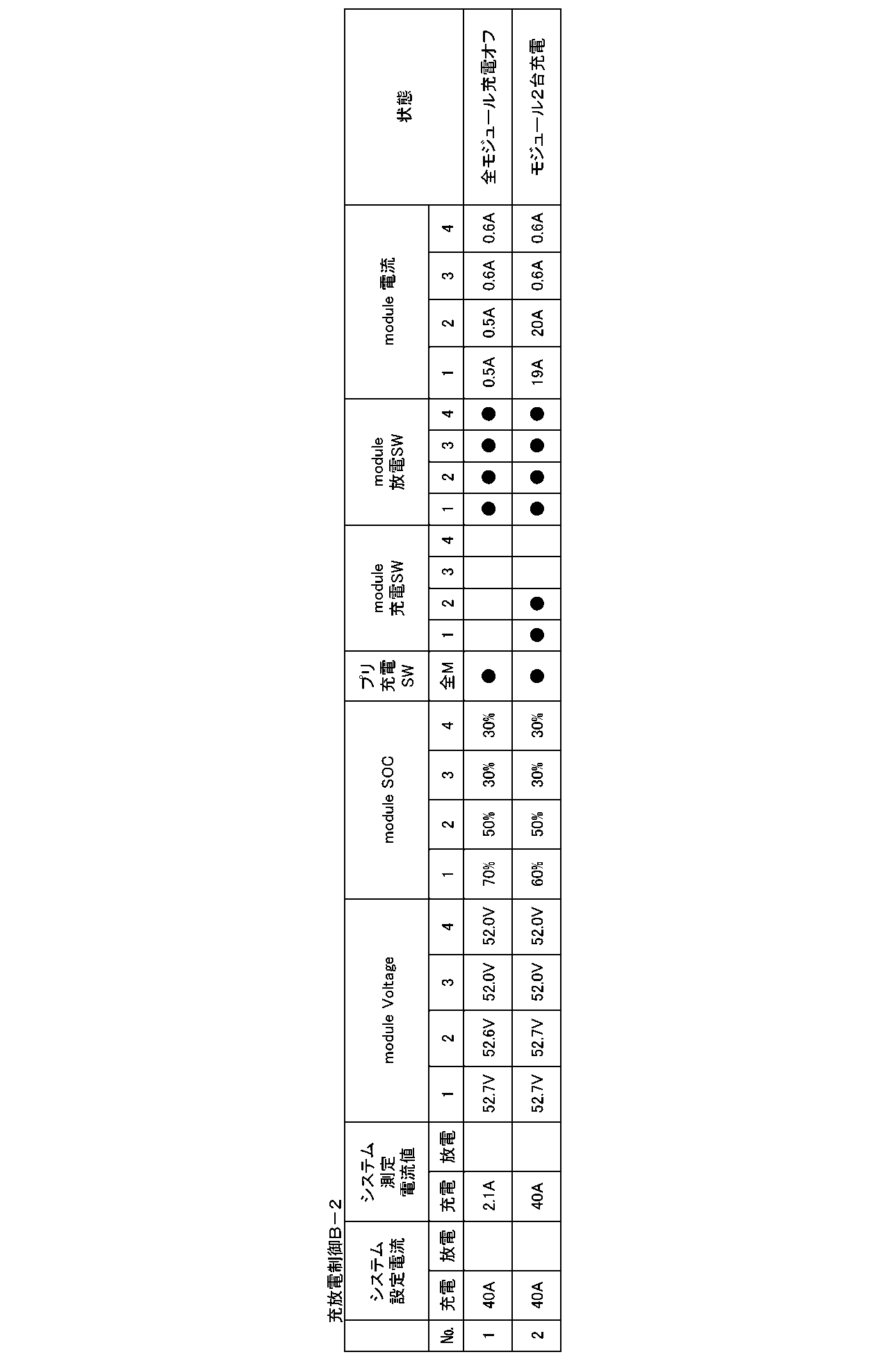
制御方法Cの処理の流れを図26に示す。ステップS21においては、常時、全てのモジュールの放電スイッチおよびプリ充電スイッチをオンする。プリ充電スイッチには、抵抗器を直列接続して抵抗器を介した小さい充電電流が流れることを許可する。抵抗器の抵抗値は、例えば10Ωである。
全てのモジュールが充電状態で、最大の測定電流値MHCと最小の測定電流値MLCとの測定電流値の差が予め設定された設定値SCB(例えば30mA)以下である。
または
全てのモジュールが放電状態で、最大の測定電流値MHCと最小の測定電流値MLCとの測定電流値の差が予め設定された設定値SCB(例えば1A)以下である。

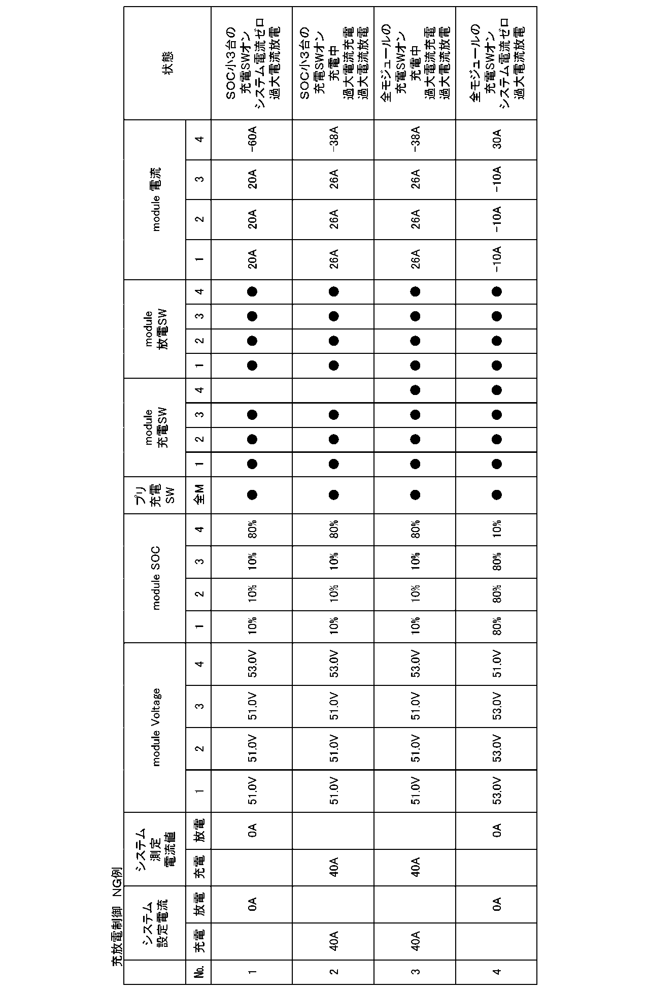
図2を参照して説明したように、モジュールMOは、蓄電部2(電池部BAT)と、コントローラ3(モジュールコントローラMOCNT)とを有している。蓄電部2は、金属製の外装ケース内に多数の電池セルを収納する構成とされる。外装ケースからは、接続用の正極端子および負極端子が導出されている。コントローラ3には、比較的大電流をオン/オフする充電スイッチおよび放電スイッチが設けられており、コントローラ3の発生する熱が比較的多い。したがって、コントローラ3の発熱に対する対策をとることが望ましい。
「蓄電装置の概略」
第2の実施の形態では、複数の蓄電装置を使用して蓄電システムが構成される。各蓄電装置には、複数のモジュールとコントローラとが含まれる。図30は、3個の蓄電装置を使用する蓄電システムの一例を示す。蓄電装置では、N個例えば3個のモジュールMOD1~MOD3が直列に接続される。モジュールの接続個数および接続形態(直列/並列)は、適宜変更できる。
モジュールの状態を監視し、電池の保護を行う。
充電、放電それぞれに独立した遮断器を備える。
本体の電源をオン/オフする主電源スイッチを持つ。
負荷/充電器CHLは、各モジュールの電池に対して充電、放電を行う。負荷/充電器CHLに限らず、パワーコンディショナ、UPS、インバータ等が接続されても良い。
ステップS32:作業者がシステムコントロールユニットSYSに対して、接続構成設定を変更する。この場合、コントローラBMU1およびBMU2が接続となるように設定する。
ステップS33:コントローラBMU2の初期化が完了する。コントローラBMU2は、充電、放電の遮断器をオフした状態で、システムコントロールユニットSYSから充電・放電許可の指示が来るまで待つ。
ステップS34:システムコントロールユニットSYSが新たに追加されたコントローラBMU2に対して初期通信を行い、初期化が完了したか否かを確認する。
ステップS35:起動が完了していることを確認する。
ステップS37:コントローラBMU1およびBMU2間の電圧差が少なく、コントローラBMU2の充電、放電を許可して良いと判断した場合、システムコントロールユニットSYSは、コントローラBMU2に対して、充電、放電許可の指示を通信にて行う。
ステップS38、S39:システムコントロールユニットSYSは、通信にてコントローラBMU1およびBMU2のそれぞれの状態を取得し、各ストリングが正常に動作したことを確認する。
例えば、1個のストリングあたりで、50Aの充電が可能であれば、50A×2=100Aとして充電可能電流が計算される。
ステップS41:外部のコントローラPCSがシステムコントロールユニットSYSに対して通信を行い、充放電可能な電流値を取得する。
ステップS42:外部コントローラPCSは、ステップS41において取得した電流値を基に、ストリングへ流す電流値を変更する。ストリングの追加によって、2個のストリング分の電流値が上限値となる。
・システムコントロールユニットSYSが通常動作しているストリングを監視し、常にシステム電圧値を計算する
・ストリング追加時には、システム電圧と追加したストリングの電圧値の差を計算し、電位差が一定値以内であれば充放電を許可する
(1)システムコントロールユニットSYSが現在動作しているコントローラBMUの情報を取得し、通常動作中のストリングの電圧の平均値を計算する。
(2)通常動作中のストリングのうち、(1)で求めた電圧の平均値に最も近いストリングの電圧をシステム電圧とする。但し、(1)で求めた平均値をそのままシステム電圧値とする方法もある。
(3)システム電圧から「±(モジュール直列数)×(閾値)V」以内のストリングはストリング間の電位差が小さいと判断し、システムコントロールユニットSYSがコントローラBMUに充電、放電を許可する。
本開示の第2の実施の形態において、使用される2次電池の一例は、正極活物質と、黒鉛等の炭素材料を負極活物質として含むリチウムイオン2次電池であり、正極材料としてオリビン構造を有する正極活物質を含有するものである。
「応用例としての住宅における電力貯蔵装置」
本開示を住宅用の電力貯蔵装置に適用した例について、図34を参照して説明する。例えば住宅101用の電力貯蔵装置100においては、火力発電102a、原子力発電102b、水力発電102c等の集中型電力系統102から電力網109、情報網112、スマートメータ107、パワーハブ108等を介し、電力が蓄電装置103に供給される。これと共に、家庭内発電装置104等の独立電源から電力が蓄電装置103に供給される。蓄電装置103に供給された電力が蓄電される。蓄電装置103を使用して、住宅101で使用する電力が給電される。住宅101に限らずビルに関しても同様の電力貯蔵装置を使用できる。
本開示を車両用の電力貯蔵装置に適用した例について、図35を参照して説明する。図35に、本開示が適用されるシリーズハイブリッドシステムを採用するハイブリッド車両の構成の一例を概略的に示す。シリーズハイブリッドシステムはエンジンで動かす発電機で発電された電力、あるいはそれを電池に一旦貯めておいた電力を用いて、電力駆動力変換装置で走行する車である。
(1)
二次電池と、前記二次電池への充電を制御する充電スイッチと、前記二次電池の放電を制御する放電スイッチと、モジュールの電圧を測定する電圧測定部とを有する複数のモジュールと、
充電スイッチおよび/または放電スイッチを制御するスイッチ制御部を有し、
前記複数のモジュールは並列接続されており、
前記スイッチ制御部は
少なくとも一つの前記モジュールの放電スイッチを所定期間オン状態に保持し、
前記モジュールの電圧を基に想定される最大モジュール充電電流が所定の値以下となる前記モジュールの充電スイッチをオン状態に制御する
蓄電装置。
(2)
前記スイッチ制御部は前記複数のモジュールの電圧の中で、前記モジュールの電圧の中で最高電圧と、前記モジュールの電圧の中で最低電圧との電圧差が所定の値より小の場合に、前記複数のモジュールの充電スイッチをオン状態に切り替える(1)に記載の蓄電装置。
(3)
前記スイッチ制御部は前記複数のモジュールのうち接続されるモジュールの個数が予め設定された数以上の場合に、前記複数のモジュールの充電スイッチをオン状態に切り替える(1)(2)の何れかに記載の蓄電装置。
(4)
前記スイッチ制御部は前記複数のモジュールの残容量が所定の値より大きい場合に、前記複数のモジュールの充電スイッチをオン状態に切り替える(1)(2)(3)の何れかに記載の蓄電装置。
(5)
前記スイッチ制御部は前記複数のモジュールの残容量の差が所定の値より小さい場合に、前記複数のモジュールの充電スイッチをオン状態に切り替える(1)(2)(3)の何れかに記載の蓄電装置。
(6)
前記スイッチ制御部は前記複数のモジュールの中で、前記モジュールの電圧が最高の第1のモジュールを選択し、
前記複数のモジュールの中で、前記第1のモジュールとモジュールの電圧の電圧差が一定値以下にある第2のモジュールの数を計数し、
前記第2のモジュールの数でシステムの充電電流を除算して、推定モジュール充電電流を求め、
前記推定モジュール充電電流が前記モジュールの最大充電電流より小の場合に、前記第1および第2のモジュールの充電スイッチをオンとする(1)に記載の蓄電装置。
(7)
前記スイッチ制御部は前記複数のモジュールの中で、前記モジュールの電圧が最高の第1のモジュールを選択し、
前記複数のモジュールの中で、残容量が最高の第3のモジュールを選択し、
前記複数のモジュールの中で、前記第1のモジュールとモジュールの電圧の電圧差が一定値以下で、且つ前記第3のモジュールと残容量の差が一定値以下にある第4のモジュールを計数し、
前記第4のモジュールの数でシステムの充電電流を除算して、推定モジュール充電電流を求め、
前記推定モジュール充電電流が前記モジュールの最大充電電流より小の場合に、前記第4のモジュールの充電スイッチをオンとする(1)に記載の蓄電装置。
(8)
前記スイッチ制御部は全ての前記モジュールが放電状態で且つ最高電流の前記モジュールの電流値と最低電流の前記モジュールの電流値との差が所定の値より小さい場合、
または全ての前記モジュールが充電状態で且つ最高電流の前記モジュールの電流値と最低電流の前記モジュールの電流値との差が所定の値より小さい場合、
全ての前記モジュールの充電スイッチをオンとする(1)に記載の蓄電装置。
(9)
前記スイッチ制御部は1台以上の前記モジュールの充電電流が前記モジュール1台の最大充電電流値よりも大きい、
または1台以上の前記モジュールの放電電流が前記モジュール1台の最大放電電流値よりも大きい場合、
全てのモジュールの充電スイッチをオフ状態に切り替える(1)乃至(8)の何れかに記載の蓄電装置。
(10)
前記スイッチ制御部は前記モジュール充電スイッチをオン状態に切り替える条件が非成立になった場合、全ての前記モジュールの充電スイッチをオフ状態に切り替える(1)乃至(8)の何れかに記載の蓄電装置。
(11)
前記スイッチ制御部は最高残容量の前記モジュールのSOC値が予め設定された値以上の場合、全ての前記モジュールの充電スイッチをオフ状態に切り替える(1)乃至(8)の何れかに記載の蓄電装置。
(12)
前記モジュールの充電スイッチをオフ状態に切り替える場合、時間のカウントを開始し、予め設定された時間が経過するまでの時間において、前記モジュールの充電スイッチをオフ状態に保持する(9)乃至(11)の何れかに記載の蓄電装置。
(12)
前記スイッチ制御部は前記モジュールの充電スイッチをオフ状態に切り替える場合、時間のカウントを開始し、予め設定された時間が経過するまでの時間において、前記モジュールの充電スイッチをオフ状態に保持する(9)乃至(11)の何れかに記載の蓄電装置。
(13)
前記モジュールの前記二次電池の正極側端子と外部正極端子間、または前記モジュールの前記二次電池の負極側端子と外部負極端子間に、プリ充電スイッチと電流制限部を直列接続し、前記プリ充電スイッチは、常にオン状態を保持する(1)乃至(12)の何れかに記載の蓄電装置。
(14)
前記モジュールの各々の二次電池の電圧が予め設定された過電圧充電値以上、または前記モジュールの充電電流が予め設定された過電流充電値以上の場合、前記充電スイッチと前記プリ充電スイッチをオフ状態に切り替え、
前記モジュールの各々の二次電池の電圧が予め設定された過電圧放電値以下、または前記モジュールの放電電流が予め設定された過電流放電値以上の場合、前記放電スイッチをオフ状態に切り替える(1)乃至(13)の何れかに記載の蓄電装置。
(15)
二次電池と、前記二次電池への充電を制御する充電スイッチと、前記二次電池の放電を制御する放電スイッチと、モジュールの電圧を測定する電圧測定部とを有する複数のモジュールと、充電スイッチおよび/または放電スイッチを制御するスイッチ制御部を有し、前記複数のモジュールは並列接続されている蓄電装置の制御方法であって、
前記スイッチ制御部によって、
少なくとも一つの前記モジュールの放電スイッチを所定期間オン状態に保持し、
前記モジュールの電圧を基に想定される最大モジュール充電電流が所定の値以下となる前記モジュールの充電スイッチをオン状態に制御する
蓄電装置の制御方法。
(16)
複数の二次電池と、前記二次電池の電圧を測定する電圧測定部と、前記電圧測定部の測定データを出力する制御部とを有するモジュールと、
複数の前記モジュールを接続して、電力を外部に出力すると共に、複数の前記モジュールを制御するコントローラとを有する蓄電装置と、
複数の前記蓄電装置を並列接続し、複数の前記蓄電装置の電力を外部に出力すると共に、前記複数の蓄電装置のそれぞれの前記コントローラと通信を行い、動作中の前記蓄電装置の電圧と追加される前記蓄電装置の電圧との電圧差が小さいか否かを判定し、前記電圧差が小さい場合に、前記追加される蓄電装置の充電または放電を許可するシステムコントロールユニットと
を備える蓄電システム。
(17)
前記並列接続されている複数の蓄電装置の電圧の平均値から求められるシステム電圧に対して、±(N×閾値)(Nは前記モジュールの接続数)の範囲内に前記追加される蓄電装置の電圧が含まれる場合に、前記電圧差が小さいと判定する(16)に記載の蓄電システム。
(18)
前記モジュールに含まれる前記二次電池がSOCの変化に対する電圧変化が小さいものである(16)(17)の何れかに記載の蓄電システム。
(19)
前記モジュールに含まれる前記二次電池がオリビン構造を有する正極活物質を有するものである(16)(17)(18)の何れかに記載の蓄電システム。
以上、本開示の実施の形態について具体的に説明したが、上述の各実施の形態に限定されるものではなく、本開示の技術的思想に基づく各種の変形が可能である。例えば、上述の実施の形態において挙げた構成、方法、工程、形状、材料および数値などはあくまでも例に過ぎず、必要に応じてこれと異なる構成、方法、工程、形状、材料および数値などを用いてもよい。例えば上述した電圧の値、電流の値、SOCの値は、一例であり、他の値を採用しても良い。また、上述の実施の形態の構成、方法、工程、形状、材料および数値などは、本開示の主旨を逸脱しない限り、互いに組み合わせることが可能である。
CNT・・・コントローラ
BAT・・・電池部
MCNT・・・モジュールコントローラ
SWd、SWd1~SWd4・・・放電スイッチ
SWc、SWc1~SWc4・・・充電スイッチ
SWp、SWp1~SWp4・・・プリ充電スイッチ
Reg、Reg1~Reg4・・・電流制限部
CHL・・・充電器/装置負荷
BMU・・・コントローラ
SYS・・・システムコントロールユニット
ST・・・ストリング
Claims (19)
- 二次電池と、前記二次電池への充電を制御する充電スイッチと、前記二次電池の放電を制御する放電スイッチと、モジュールの電圧を測定する電圧測定部とを有する複数のモジュールと、
充電スイッチおよび/または放電スイッチを制御するスイッチ制御部を有し、
前記複数のモジュールは並列接続されており、
前記スイッチ制御部は
少なくとも一つの前記モジュールの放電スイッチを所定期間オン状態に保持し、
前記モジュールの電圧を基に想定される最大モジュール充電電流が所定の値以下となる前記モジュールの充電スイッチをオン状態に制御する
蓄電装置。 - 前記スイッチ制御部は前記複数のモジュールの電圧の中で、前記モジュールの電圧の中で最高電圧と、前記モジュールの電圧の中で最低電圧との電圧差が所定の値より小の場合に、前記複数のモジュールの充電スイッチをオン状態に切り替える請求項1に記載の蓄電装置。
- 前記スイッチ制御部は前記複数のモジュールのうち接続されるモジュールの個数が予め設定された数以上の場合に、前記複数のモジュールの充電スイッチをオン状態に切り替える請求項2に記載の蓄電装置。
- 前記スイッチ制御部は前記複数のモジュールの残容量が所定の値より大きい場合に、前記複数のモジュールの充電スイッチをオン状態に切り替える請求項3に記載の蓄電装置。
- 前記スイッチ制御部は前記複数のモジュールの残容量の差が所定の値より小さい場合に、前記複数のモジュールの充電スイッチをオン状態に切り替える請求項3に記載の蓄電装置。
- 前記スイッチ制御部は前記複数のモジュールの中で、前記モジュールの電圧が最高の第1のモジュールを選択し、
前記複数のモジュールの中で、前記第1のモジュールとモジュールの電圧の電圧差が一定値以下にある第2のモジュールの数を計数し、
前記第2のモジュールの数でシステムの充電電流を除算して、推定モジュール充電電流を求め、
前記推定モジュール充電電流が前記モジュールの最大充電電流より小の場合に、前記第1および第2のモジュールの充電スイッチをオンとする請求項1に記載の蓄電装置。 - 前記スイッチ制御部は前記複数のモジュールの中で、前記モジュールの電圧が最高の第1のモジュールを選択し、
前記複数のモジュールの中で、残容量が最高の第3のモジュールを選択し、
前記複数のモジュールの中で、前記第1のモジュールとモジュールの電圧の電圧差が一定値以下で、且つ前記第3のモジュールと残容量の差が一定値以下にある第4のモジュールを計数し、
前記第4のモジュールの数でシステムの充電電流を除算して、推定モジュール充電電流を求め、
前記推定モジュール充電電流が前記モジュールの最大充電電流より小の場合に、前記第4のモジュールの充電スイッチをオンとする請求項1に記載の蓄電装置。 - 前記スイッチ制御部は全ての前記モジュールが放電状態で且つ最高電流の前記モジュールの電流値と最低電流の前記モジュールの電流値との差が所定の値より小さい場合、
または全ての前記モジュールが充電状態で且つ最高電流の前記モジュールの電流値と最低電流の前記モジュールの電流値との差が所定の値より小さい場合、
全ての前記モジュールの充電スイッチをオンとする請求項1に記載の蓄電装置。 - 前記スイッチ制御部は1台以上の前記モジュールの充電電流が前記モジュール1台の最大充電電流値よりも大きい、
または1台以上の前記モジュールの放電電流が前記モジュール1台の最大放電電流値よりも大きい場合、
全てのモジュールの充電スイッチをオフ状態に切り替える請求項1に記載の蓄電装置。 - 前記スイッチ制御部は前記モジュール充電スイッチをオン状態に切り替える条件が非成立になった場合、全ての前記モジュールの充電スイッチをオフ状態に切り替える請求項1に記載の蓄電装置。
- 前記スイッチ制御部は最高残容量の前記モジュールのSOC値が予め設定された値以上の場合、全ての前記モジュールの充電スイッチをオフ状態に切り替える請求項1に記載の蓄電装置。
- 前記スイッチ制御部は前記モジュールの充電スイッチをオフ状態に切り替える場合、時間のカウントを開始し、予め設定された時間が経過するまでの時間において、前記モジュールの充電スイッチをオフ状態に保持する請求項10に記載の蓄電装置。
- 前記モジュールの前記二次電池の正極側端子と外部正極端子間、または前記モジュールの前記二次電池の負極側端子と外部負極端子間に、プリ充電スイッチと電流制限部を直列接続し、前記プリ充電スイッチは、常にオン状態を保持する請求項1に記載の蓄電装置。
- 前記モジュールの各々の二次電池の電圧が予め設定された過電圧充電値以上、または前記モジュールの充電電流が予め設定された過電流充電値以上の場合、前記充電スイッチと前記プリ充電スイッチをオフ状態に切り替え、
前記モジュールの各々の二次電池の電圧が予め設定された過電圧放電値以下、または前記モジュールの放電電流が予め設定された過電流放電値以上の場合、前記放電スイッチをオフ状態に切り替える請求項13に記載の蓄電装置。 - 二次電池と、前記二次電池への充電を制御する充電スイッチと、前記二次電池の放電を制御する放電スイッチと、モジュールの電圧を測定する電圧測定部とを有する複数のモジュールと、充電スイッチおよび/または放電スイッチを制御するスイッチ制御部を有し、前記複数のモジュールは並列接続されている蓄電装置の制御方法であって、
前記スイッチ制御部によって、
少なくとも一つの前記モジュールの放電スイッチを所定期間オン状態に保持し、
前記モジュールの電圧を基に想定される最大モジュール充電電流が所定の値以下となる前記モジュールの充電スイッチをオン状態に制御する
蓄電装置の制御方法。 - 複数の二次電池と、前記二次電池の電圧を測定する電圧測定部と、前記電圧測定部の測定データを出力する制御部とを有するモジュールと、
複数の前記モジュールを接続して、電力を外部に出力すると共に、複数の前記モジュールを制御するコントローラとを有する蓄電装置と、
複数の前記蓄電装置を並列接続し、複数の前記蓄電装置の電力を外部に出力すると共に、前記複数の蓄電装置のそれぞれの前記コントローラと通信を行い、動作中の前記蓄電装置の電圧と追加される前記蓄電装置の電圧との電圧差が小さいか否かを判定し、前記電圧差が小さい場合に、前記追加される蓄電装置の充電または放電を許可するシステムコントロールユニットと
を備える蓄電システム。 - 前記並列接続されている複数の蓄電装置の電圧の平均値から求められるシステム電圧に対して、±(N×閾値)(Nは前記モジュールの接続数)の範囲内に前記追加される蓄電装置の電圧が含まれる場合に、前記電圧差が小さいと判定する請求項16に記載の蓄電システム。
- 前記モジュールに含まれる前記二次電池がSOCの変化に対する電圧変化が小さいものである請求項16に記載の蓄電システム。
- 前記モジュールに含まれる前記二次電池がオリビン構造を有する正極活物質を有するものである請求項16に記載の蓄電システム。
Priority Applications (4)
| Application Number | Priority Date | Filing Date | Title |
|---|---|---|---|
| CN201480017315.5A CN105075056B (zh) | 2013-03-28 | 2014-03-06 | 蓄电装置、蓄电系统、以及蓄电装置的控制方法 |
| EP14772691.3A EP2980954B1 (en) | 2013-03-28 | 2014-03-06 | Power storage device, power storage system, and power storage device control method |
| JP2015508005A JP6225986B2 (ja) | 2013-03-28 | 2014-03-06 | 蓄電装置および蓄電装置の制御方法 |
| US14/778,980 US10008862B2 (en) | 2013-03-28 | 2014-03-06 | Power storage device, power storage system, and control method of power storage device |
Applications Claiming Priority (4)
| Application Number | Priority Date | Filing Date | Title |
|---|---|---|---|
| JP2013-069403 | 2013-03-28 | ||
| JP2013069403 | 2013-03-28 | ||
| JP2013185237 | 2013-09-06 | ||
| JP2013-185237 | 2013-09-06 |
Publications (1)
| Publication Number | Publication Date |
|---|---|
| WO2014155986A1 true WO2014155986A1 (ja) | 2014-10-02 |
Family
ID=51623007
Family Applications (1)
| Application Number | Title | Priority Date | Filing Date |
|---|---|---|---|
| PCT/JP2014/001230 WO2014155986A1 (ja) | 2013-03-28 | 2014-03-06 | 蓄電装置、蓄電システムおよび蓄電装置の制御方法 |
Country Status (5)
| Country | Link |
|---|---|
| US (1) | US10008862B2 (ja) |
| EP (1) | EP2980954B1 (ja) |
| JP (1) | JP6225986B2 (ja) |
| CN (1) | CN105075056B (ja) |
| WO (1) | WO2014155986A1 (ja) |
Cited By (10)
| Publication number | Priority date | Publication date | Assignee | Title |
|---|---|---|---|---|
| KR20160115385A (ko) * | 2015-03-27 | 2016-10-06 | 삼성전자주식회사 | 전자장치의 전원을 제어하는 방법 및 장치 |
| US20160336781A1 (en) * | 2015-05-14 | 2016-11-17 | Samsung Sdi Co., Ltd. | Energy storage system and driving method thereof |
| WO2016197413A1 (zh) * | 2015-06-11 | 2016-12-15 | 深圳市华宝新能源股份有限公司 | 储能充电设备及移动充电设备 |
| CN106356909A (zh) * | 2015-07-22 | 2017-01-25 | 比亚迪股份有限公司 | 电池管理系统和方法 |
| JP2018157666A (ja) * | 2017-03-16 | 2018-10-04 | エイブリック株式会社 | 充放電制御回路およびバッテリ装置 |
| JP2020018092A (ja) * | 2018-07-25 | 2020-01-30 | ダイムラー・アクチェンゲゼルシャフトDaimler AG | 充電制御装置 |
| WO2020086973A1 (en) | 2018-10-26 | 2020-04-30 | Cummins Inc. | BATTERY CHARGING AND DISCHARGING OF MULTIPLE PACKS AT DIFFERENT STATES OF CHARGE (SOCs) |
| US10693198B2 (en) | 2015-06-30 | 2020-06-23 | Gs Yuasa International Ltd. | Controller, energy storage apparatus, energy storage system, moving object, backup power supply, and controller method |
| JP2020134687A (ja) * | 2019-02-19 | 2020-08-31 | 日清工業有限公司 | ストロボ装置及びストロボ装置の充電制御方法 |
| US10784541B2 (en) | 2015-02-06 | 2020-09-22 | Zte Corporation | Storage battery device, and charging-discharging monitoring method, device and system thereof |
Families Citing this family (42)
| Publication number | Priority date | Publication date | Assignee | Title |
|---|---|---|---|---|
| US20160241036A1 (en) * | 2012-09-27 | 2016-08-18 | James F. Wolter | Energy apparatuses, energy systems, and energy management methods including energy storage |
| US10008862B2 (en) | 2013-03-28 | 2018-06-26 | Murata Manufacturing Co., Ltd. | Power storage device, power storage system, and control method of power storage device |
| DE102014201346A1 (de) * | 2014-01-27 | 2015-07-30 | Robert Bosch Gmbh | Bordnetz |
| WO2016029202A1 (en) * | 2014-08-22 | 2016-02-25 | Pathion Inc. | Method and apparatus for performing string-level dynamic reconfiguration in an energy system |
| KR102296132B1 (ko) * | 2015-02-16 | 2021-08-31 | 삼성에스디아이 주식회사 | 배터리 팩 및 그의 구동방법 |
| JP6466761B2 (ja) * | 2015-03-31 | 2019-02-06 | ラピスセミコンダクタ株式会社 | 半導体装置、及び電源供給方法 |
| EP3091633B1 (en) * | 2015-05-07 | 2018-02-07 | Richtek Technology Corporation | Adaptive power converter of mobile charger |
| US10396582B2 (en) * | 2015-07-01 | 2019-08-27 | Maxim Integrated Products, Inc. | Master slave charging architecture with communication between chargers |
| CN107750413B (zh) * | 2015-11-18 | 2022-07-22 | 艾达司股份有限公司 | 控制装置、蓄电装置及蓄电系统 |
| JP6254139B2 (ja) * | 2015-11-28 | 2017-12-27 | 本田技研工業株式会社 | 電力供給システム及び輸送機器、並びに、電力伝送方法 |
| WO2017150713A1 (ja) * | 2016-03-04 | 2017-09-08 | ヤマハ発動機株式会社 | 車両 |
| US11128158B2 (en) * | 2016-03-09 | 2021-09-21 | Servato Corp. | Battery management system and related techniques for adaptive, dynamic control of battery charging |
| US10122208B2 (en) * | 2016-05-20 | 2018-11-06 | Kabushiki Kaisha Toshiba | Power device |
| JP6828296B2 (ja) * | 2016-08-09 | 2021-02-10 | 株式会社Gsユアサ | 蓄電装置および蓄電装置の充電制御方法 |
| JP6883396B2 (ja) * | 2016-08-25 | 2021-06-09 | 矢崎総業株式会社 | 急速充電装置 |
| TWI633738B (zh) * | 2016-09-07 | 2018-08-21 | 華碩電腦股份有限公司 | 儲能單元充放電模組及其充放電方法 |
| US10650621B1 (en) | 2016-09-13 | 2020-05-12 | Iocurrents, Inc. | Interfacing with a vehicular controller area network |
| KR102215350B1 (ko) * | 2016-09-21 | 2021-02-15 | 가부시키가이샤 인비젼 에이이에스씨 재팬 | 전원 시스템 |
| US10199847B2 (en) * | 2016-10-18 | 2019-02-05 | Microsoft Technology Licensing, Llc | Battery including programmable components |
| JP6787214B2 (ja) * | 2017-03-27 | 2020-11-18 | ブラザー工業株式会社 | 充電器及び充電制御方法 |
| JP6323822B1 (ja) * | 2017-07-07 | 2018-05-16 | Mirai−Labo株式会社 | 電源装置および電源制御方法 |
| JP6928347B2 (ja) * | 2017-08-02 | 2021-09-01 | NExT−e Solutions株式会社 | 管理装置、蓄電装置、蓄電システム、及び、電気機器 |
| JP6794960B2 (ja) * | 2017-08-22 | 2020-12-02 | トヨタ自動車株式会社 | 電源システム |
| CN111149269B (zh) * | 2017-10-04 | 2024-03-29 | 株式会社Aesc日本 | 蓄电池包的检查方法及检查装置 |
| KR102256094B1 (ko) * | 2017-11-28 | 2021-05-25 | 주식회사 엘지에너지솔루션 | 배터리 팩 |
| KR102361334B1 (ko) * | 2018-05-09 | 2022-02-09 | 주식회사 엘지에너지솔루션 | 배터리 제어 장치 및 이를 포함하는 에너지 저장 시스템 |
| CN109119708A (zh) * | 2018-08-17 | 2019-01-01 | 深圳市铭隆动力科技有限公司 | 一种多功能电池动力系统 |
| JP7025716B2 (ja) * | 2018-11-29 | 2022-02-25 | トヨタ自動車株式会社 | 電源システム |
| JP7129008B2 (ja) | 2018-11-29 | 2022-09-01 | トヨタ自動車株式会社 | 電源システム |
| US11251637B2 (en) | 2018-12-04 | 2022-02-15 | Mobile Escapes, Llc | Mobile power system with multiple converters and related platforms and methods |
| CN111384736A (zh) * | 2018-12-29 | 2020-07-07 | 中兴通讯股份有限公司 | 充放电装置、控制方法及装置、电池装置、存储介质 |
| KR20210045841A (ko) * | 2019-10-17 | 2021-04-27 | 삼성에스디아이 주식회사 | 배터리 시스템 |
| CN110752645A (zh) * | 2019-11-25 | 2020-02-04 | 广东博力威科技股份有限公司 | 多个电池的并联充放电管理系统 |
| CN112848969A (zh) * | 2019-11-27 | 2021-05-28 | 光阳工业股份有限公司 | 电动车辆的电池并联控制方法 |
| CN110940924B (zh) * | 2019-12-17 | 2022-11-22 | 格力博(江苏)股份有限公司 | 一种电池包诊断方法以及电池包诊断装置 |
| EP4094341B1 (en) * | 2020-01-21 | 2024-03-06 | Ola Electric Mobility B.V. | Battery system and battery management method |
| FR3109480B1 (fr) * | 2020-04-16 | 2023-11-17 | Commissariat Energie Atomique | Assemblage de cellules de stockage ou de production d’énergie électrique comprenant un circuit de gestion des cellules |
| JP7327280B2 (ja) * | 2020-05-29 | 2023-08-16 | トヨタ自動車株式会社 | 燃料電池システム |
| CN115734890A (zh) * | 2020-06-25 | 2023-03-03 | Tvs电机有限公司 | 储能装置 |
| EP4169760A1 (en) * | 2021-10-25 | 2023-04-26 | Aptiv Technologies Limited | Vehicle power distribution circuit and vehicle power system |
| DE102021212023A1 (de) | 2021-10-26 | 2023-04-27 | Robert Bosch Gesellschaft mit beschränkter Haftung | Verfahren zum Betreiben eines Batteriesystems, Batteriesystem |
| US11777334B2 (en) * | 2021-11-11 | 2023-10-03 | Beta Air, Llc | System for charging multiple power sources and monitoring diode currents for faults |
Citations (5)
| Publication number | Priority date | Publication date | Assignee | Title |
|---|---|---|---|---|
| JPH04281339A (ja) * | 1991-03-07 | 1992-10-06 | Fuji Electric Co Ltd | 無停電電源装置のバッテリー回路 |
| JP2002095173A (ja) | 2000-09-08 | 2002-03-29 | Sharp Corp | バッテリ制御装置 |
| JP2003244854A (ja) * | 2002-02-13 | 2003-08-29 | Mitsubishi Heavy Ind Ltd | 蓄電装置の充放電制御装置及び充放電制御方法並びに電力貯蔵システム |
| JP2005176461A (ja) | 2003-12-09 | 2005-06-30 | Matsushita Electric Ind Co Ltd | 直流無停電電源装置 |
| JP2010220280A (ja) * | 2009-03-13 | 2010-09-30 | Panasonic Corp | 充放電制御回路、電源装置、及び電源装置の制御方法 |
Family Cites Families (10)
| Publication number | Priority date | Publication date | Assignee | Title |
|---|---|---|---|---|
| FR2815786B1 (fr) * | 2000-10-23 | 2003-01-17 | Cit Alcatel | Procede, agencement et ensemble d'interface destines a permettre la charge de batteries electriques de natures au moyen d'un meme dispositif |
| US6879134B2 (en) * | 2003-02-11 | 2005-04-12 | O2Micro International Limited | Selector circuit for power management in multiple battery systems |
| US7647191B2 (en) * | 2005-09-05 | 2010-01-12 | Panasonic Corporation | Accumulator state detection device |
| JP4388094B2 (ja) * | 2007-03-28 | 2009-12-24 | 株式会社東芝 | 組電池の保護装置及び電池パック装置 |
| JP5486780B2 (ja) * | 2008-07-01 | 2014-05-07 | 株式会社日立製作所 | 電池システム |
| CN102208820B (zh) * | 2010-03-29 | 2013-08-21 | 比亚迪股份有限公司 | 一种储能电池组并联装置及其控制方法 |
| WO2012043723A1 (ja) * | 2010-10-01 | 2012-04-05 | 三洋電機株式会社 | 電源装置 |
| JP5677261B2 (ja) * | 2011-09-30 | 2015-02-25 | 株式会社日立製作所 | 蓄電システム |
| US9711962B2 (en) * | 2012-07-09 | 2017-07-18 | Davide Andrea | System and method for isolated DC to DC converter |
| US10008862B2 (en) | 2013-03-28 | 2018-06-26 | Murata Manufacturing Co., Ltd. | Power storage device, power storage system, and control method of power storage device |
-
2014
- 2014-03-06 US US14/778,980 patent/US10008862B2/en active Active
- 2014-03-06 JP JP2015508005A patent/JP6225986B2/ja active Active
- 2014-03-06 EP EP14772691.3A patent/EP2980954B1/en active Active
- 2014-03-06 WO PCT/JP2014/001230 patent/WO2014155986A1/ja active Application Filing
- 2014-03-06 CN CN201480017315.5A patent/CN105075056B/zh active Active
Patent Citations (5)
| Publication number | Priority date | Publication date | Assignee | Title |
|---|---|---|---|---|
| JPH04281339A (ja) * | 1991-03-07 | 1992-10-06 | Fuji Electric Co Ltd | 無停電電源装置のバッテリー回路 |
| JP2002095173A (ja) | 2000-09-08 | 2002-03-29 | Sharp Corp | バッテリ制御装置 |
| JP2003244854A (ja) * | 2002-02-13 | 2003-08-29 | Mitsubishi Heavy Ind Ltd | 蓄電装置の充放電制御装置及び充放電制御方法並びに電力貯蔵システム |
| JP2005176461A (ja) | 2003-12-09 | 2005-06-30 | Matsushita Electric Ind Co Ltd | 直流無停電電源装置 |
| JP2010220280A (ja) * | 2009-03-13 | 2010-09-30 | Panasonic Corp | 充放電制御回路、電源装置、及び電源装置の制御方法 |
Non-Patent Citations (1)
| Title |
|---|
| See also references of EP2980954A4 |
Cited By (19)
| Publication number | Priority date | Publication date | Assignee | Title |
|---|---|---|---|---|
| US10784541B2 (en) | 2015-02-06 | 2020-09-22 | Zte Corporation | Storage battery device, and charging-discharging monitoring method, device and system thereof |
| KR20160115385A (ko) * | 2015-03-27 | 2016-10-06 | 삼성전자주식회사 | 전자장치의 전원을 제어하는 방법 및 장치 |
| KR102382081B1 (ko) * | 2015-03-27 | 2022-04-01 | 삼성전자 주식회사 | 전자장치의 전원을 제어하는 방법 및 장치 |
| US20160336781A1 (en) * | 2015-05-14 | 2016-11-17 | Samsung Sdi Co., Ltd. | Energy storage system and driving method thereof |
| CN106160067A (zh) * | 2015-05-14 | 2016-11-23 | 三星Sdi株式会社 | 能量存储系统及其驱动方法 |
| KR20160133978A (ko) * | 2015-05-14 | 2016-11-23 | 삼성에스디아이 주식회사 | 에너지 저장 시스템 및 그 구동 방법 |
| CN106160067B (zh) * | 2015-05-14 | 2021-06-25 | 三星Sdi株式会社 | 能量存储系统及其驱动方法 |
| US10122187B2 (en) * | 2015-05-14 | 2018-11-06 | Samsung Sdi Co., Ltd. | Energy storage system and driving method thereof |
| WO2016197413A1 (zh) * | 2015-06-11 | 2016-12-15 | 深圳市华宝新能源股份有限公司 | 储能充电设备及移动充电设备 |
| US10693198B2 (en) | 2015-06-30 | 2020-06-23 | Gs Yuasa International Ltd. | Controller, energy storage apparatus, energy storage system, moving object, backup power supply, and controller method |
| CN106356909A (zh) * | 2015-07-22 | 2017-01-25 | 比亚迪股份有限公司 | 电池管理系统和方法 |
| JP2018157666A (ja) * | 2017-03-16 | 2018-10-04 | エイブリック株式会社 | 充放電制御回路およびバッテリ装置 |
| JP2020018092A (ja) * | 2018-07-25 | 2020-01-30 | ダイムラー・アクチェンゲゼルシャフトDaimler AG | 充電制御装置 |
| JP7137387B2 (ja) | 2018-07-25 | 2022-09-14 | メルセデス・ベンツ グループ アクチェンゲゼルシャフト | 充電制御装置、及び電動車両 |
| WO2020086973A1 (en) | 2018-10-26 | 2020-04-30 | Cummins Inc. | BATTERY CHARGING AND DISCHARGING OF MULTIPLE PACKS AT DIFFERENT STATES OF CHARGE (SOCs) |
| CN112533788A (zh) * | 2018-10-26 | 2021-03-19 | 康明斯公司 | 处于不同荷电状态(soc)的多个电池组的电池充电和放电 |
| EP3784516A4 (en) * | 2018-10-26 | 2022-04-27 | Cummins, Inc. | BATTERY CHARGING AND DISCHARGE OF MULTIPLE PACKS AT DIFFERENT STATE OF CHARGE (SOCS) |
| CN112533788B (zh) * | 2018-10-26 | 2023-12-01 | 康明斯公司 | 处于不同荷电状态(soc)的多个电池组的电池充电和放电 |
| JP2020134687A (ja) * | 2019-02-19 | 2020-08-31 | 日清工業有限公司 | ストロボ装置及びストロボ装置の充電制御方法 |
Also Published As
| Publication number | Publication date |
|---|---|
| EP2980954A4 (en) | 2016-11-23 |
| EP2980954A1 (en) | 2016-02-03 |
| JP6225986B2 (ja) | 2017-11-08 |
| US10008862B2 (en) | 2018-06-26 |
| CN105075056A (zh) | 2015-11-18 |
| JPWO2014155986A1 (ja) | 2017-02-16 |
| CN105075056B (zh) | 2019-01-15 |
| US20160049813A1 (en) | 2016-02-18 |
| EP2980954B1 (en) | 2019-12-18 |
Similar Documents
| Publication | Publication Date | Title |
|---|---|---|
| JP6225986B2 (ja) | 蓄電装置および蓄電装置の制御方法 | |
| EP3183791B1 (en) | Electric storage system | |
| US10230249B2 (en) | Battery pack, method for charging/discharging same, and power consumption device | |
| JP5954144B2 (ja) | 制御装置、制御方法、制御システムおよび電動車両 | |
| US9276422B2 (en) | Battery pack and electric power consuming apparatus | |
| US10587127B2 (en) | Charging device, charging control method, electricity storage device, power storage device, power system, and electric vehicle | |
| JP6347212B2 (ja) | 制御装置、蓄電モジュール、電動車両、電源システムおよび制御方法 | |
| JP5929526B2 (ja) | 電源供給装置および電源切り換え方法 | |
| US9331494B2 (en) | Battery system | |
| US20110175564A1 (en) | Battery pack including sensing board and power storage system employing the same | |
| CN102570531B (zh) | 多级充电均衡控制装置及方法 | |
| KR20180104873A (ko) | 리튬 배터리 보호 시스템 | |
| Kilic et al. | Design of master and slave modules on battery management system for electric vehicles | |
| RU2561826C2 (ru) | Батарея электрических накопителей энергии с распределенной аналитической системой управления | |
| KR20220129735A (ko) | 모듈식 배터리 관리 시스템 |
Legal Events
| Date | Code | Title | Description |
|---|---|---|---|
| WWE | Wipo information: entry into national phase |
Ref document number: 201480017315.5 Country of ref document: CN |
|
| 121 | Ep: the epo has been informed by wipo that ep was designated in this application |
Ref document number: 14772691 Country of ref document: EP Kind code of ref document: A1 |
|
| ENP | Entry into the national phase |
Ref document number: 2015508005 Country of ref document: JP Kind code of ref document: A |
|
| WWE | Wipo information: entry into national phase |
Ref document number: 14778980 Country of ref document: US Ref document number: 2014772691 Country of ref document: EP |
|
| NENP | Non-entry into the national phase |
Ref country code: DE |