WO2014155901A1 - 燃料電池用の触媒インクの製造方法、燃料電池用の触媒層の製造方法、燃料電池用の膜電極接合体の製造方法 - Google Patents
燃料電池用の触媒インクの製造方法、燃料電池用の触媒層の製造方法、燃料電池用の膜電極接合体の製造方法 Download PDFInfo
- Publication number
- WO2014155901A1 WO2014155901A1 PCT/JP2014/000116 JP2014000116W WO2014155901A1 WO 2014155901 A1 WO2014155901 A1 WO 2014155901A1 JP 2014000116 W JP2014000116 W JP 2014000116W WO 2014155901 A1 WO2014155901 A1 WO 2014155901A1
- Authority
- WO
- WIPO (PCT)
- Prior art keywords
- catalyst
- fuel cell
- producing
- catalyst ink
- ionomer solution
- Prior art date
- Legal status (The legal status is an assumption and is not a legal conclusion. Google has not performed a legal analysis and makes no representation as to the accuracy of the status listed.)
- Ceased
Links
Images



Classifications
-
- H—ELECTRICITY
- H01—ELECTRIC ELEMENTS
- H01M—PROCESSES OR MEANS, e.g. BATTERIES, FOR THE DIRECT CONVERSION OF CHEMICAL ENERGY INTO ELECTRICAL ENERGY
- H01M4/00—Electrodes
- H01M4/86—Inert electrodes with catalytic activity, e.g. for fuel cells
- H01M4/88—Processes of manufacture
- H01M4/8825—Methods for deposition of the catalytic active composition
- H01M4/8828—Coating with slurry or ink
-
- C—CHEMISTRY; METALLURGY
- C09—DYES; PAINTS; POLISHES; NATURAL RESINS; ADHESIVES; COMPOSITIONS NOT OTHERWISE PROVIDED FOR; APPLICATIONS OF MATERIALS NOT OTHERWISE PROVIDED FOR
- C09D—COATING COMPOSITIONS, e.g. PAINTS, VARNISHES OR LACQUERS; FILLING PASTES; CHEMICAL PAINT OR INK REMOVERS; INKS; CORRECTING FLUIDS; WOODSTAINS; PASTES OR SOLIDS FOR COLOURING OR PRINTING; USE OF MATERIALS THEREFOR
- C09D11/00—Inks
- C09D11/02—Printing inks
- C09D11/03—Printing inks characterised by features other than the chemical nature of the binder
- C09D11/037—Printing inks characterised by features other than the chemical nature of the binder characterised by the pigment
-
- C—CHEMISTRY; METALLURGY
- C09—DYES; PAINTS; POLISHES; NATURAL RESINS; ADHESIVES; COMPOSITIONS NOT OTHERWISE PROVIDED FOR; APPLICATIONS OF MATERIALS NOT OTHERWISE PROVIDED FOR
- C09D—COATING COMPOSITIONS, e.g. PAINTS, VARNISHES OR LACQUERS; FILLING PASTES; CHEMICAL PAINT OR INK REMOVERS; INKS; CORRECTING FLUIDS; WOODSTAINS; PASTES OR SOLIDS FOR COLOURING OR PRINTING; USE OF MATERIALS THEREFOR
- C09D11/00—Inks
- C09D11/02—Printing inks
- C09D11/10—Printing inks based on artificial resins
-
- H—ELECTRICITY
- H01—ELECTRIC ELEMENTS
- H01M—PROCESSES OR MEANS, e.g. BATTERIES, FOR THE DIRECT CONVERSION OF CHEMICAL ENERGY INTO ELECTRICAL ENERGY
- H01M4/00—Electrodes
- H01M4/86—Inert electrodes with catalytic activity, e.g. for fuel cells
- H01M4/8663—Selection of inactive substances as ingredients for catalytic active masses, e.g. binders, fillers
-
- H—ELECTRICITY
- H01—ELECTRIC ELEMENTS
- H01M—PROCESSES OR MEANS, e.g. BATTERIES, FOR THE DIRECT CONVERSION OF CHEMICAL ENERGY INTO ELECTRICAL ENERGY
- H01M4/00—Electrodes
- H01M4/86—Inert electrodes with catalytic activity, e.g. for fuel cells
- H01M4/88—Processes of manufacture
-
- H—ELECTRICITY
- H01—ELECTRIC ELEMENTS
- H01M—PROCESSES OR MEANS, e.g. BATTERIES, FOR THE DIRECT CONVERSION OF CHEMICAL ENERGY INTO ELECTRICAL ENERGY
- H01M4/00—Electrodes
- H01M4/86—Inert electrodes with catalytic activity, e.g. for fuel cells
- H01M4/88—Processes of manufacture
- H01M4/8878—Treatment steps after deposition of the catalytic active composition or after shaping of the electrode being free-standing body
- H01M4/8882—Heat treatment, e.g. drying, baking
-
- H—ELECTRICITY
- H01—ELECTRIC ELEMENTS
- H01M—PROCESSES OR MEANS, e.g. BATTERIES, FOR THE DIRECT CONVERSION OF CHEMICAL ENERGY INTO ELECTRICAL ENERGY
- H01M4/00—Electrodes
- H01M4/86—Inert electrodes with catalytic activity, e.g. for fuel cells
- H01M4/88—Processes of manufacture
- H01M4/8803—Supports for the deposition of the catalytic active composition
- H01M4/8807—Gas diffusion layers
-
- H—ELECTRICITY
- H01—ELECTRIC ELEMENTS
- H01M—PROCESSES OR MEANS, e.g. BATTERIES, FOR THE DIRECT CONVERSION OF CHEMICAL ENERGY INTO ELECTRICAL ENERGY
- H01M8/00—Fuel cells; Manufacture thereof
- H01M8/10—Fuel cells with solid electrolytes
- H01M8/1004—Fuel cells with solid electrolytes characterised by membrane-electrode assemblies [MEA]
-
- Y—GENERAL TAGGING OF NEW TECHNOLOGICAL DEVELOPMENTS; GENERAL TAGGING OF CROSS-SECTIONAL TECHNOLOGIES SPANNING OVER SEVERAL SECTIONS OF THE IPC; TECHNICAL SUBJECTS COVERED BY FORMER USPC CROSS-REFERENCE ART COLLECTIONS [XRACs] AND DIGESTS
- Y02—TECHNOLOGIES OR APPLICATIONS FOR MITIGATION OR ADAPTATION AGAINST CLIMATE CHANGE
- Y02E—REDUCTION OF GREENHOUSE GAS [GHG] EMISSIONS, RELATED TO ENERGY GENERATION, TRANSMISSION OR DISTRIBUTION
- Y02E60/00—Enabling technologies; Technologies with a potential or indirect contribution to GHG emissions mitigation
- Y02E60/30—Hydrogen technology
- Y02E60/50—Fuel cells
-
- Y—GENERAL TAGGING OF NEW TECHNOLOGICAL DEVELOPMENTS; GENERAL TAGGING OF CROSS-SECTIONAL TECHNOLOGIES SPANNING OVER SEVERAL SECTIONS OF THE IPC; TECHNICAL SUBJECTS COVERED BY FORMER USPC CROSS-REFERENCE ART COLLECTIONS [XRACs] AND DIGESTS
- Y02—TECHNOLOGIES OR APPLICATIONS FOR MITIGATION OR ADAPTATION AGAINST CLIMATE CHANGE
- Y02P—CLIMATE CHANGE MITIGATION TECHNOLOGIES IN THE PRODUCTION OR PROCESSING OF GOODS
- Y02P70/00—Climate change mitigation technologies in the production process for final industrial or consumer products
- Y02P70/50—Manufacturing or production processes characterised by the final manufactured product
Definitions
- the present invention relates to a method for producing a catalyst ink for a fuel cell, a method for producing a catalyst layer for a fuel cell, and a method for producing a membrane electrode assembly for a fuel cell.
- a method for producing a catalyst ink for a fuel cell (a) water and lower alcohol (4 or less carbon atoms) are mixed in an electrode catalyst to disperse electrode catalyst particles to obtain a dispersion, and (b) ionomer is mixed in a solvent.
- step (D) A production method comprising a step of increasing the viscosity of the dispersion by mixing the dispersion obtained in step (c) with a low relative dielectric constant dispersion medium having a relative dielectric constant of 20 or less at 20 ° C. It has been known.
- the catalyst layer produced using the catalyst ink is likely to crack.
- a larger ion exchange equivalent is preferable.
- the ion exchange equivalent (EW value) is 900 g / mol or more, there is a problem that it is not easy to increase the viscosity of the ionomer solution (for example, to prepare a storage elastic modulus of 150 Pa or more).
- the present invention has been made to solve at least a part of the problems described above, and can be realized as the following forms.
- a method for producing a catalyst ink for a fuel cell is provided.
- This method for producing a catalyst ink for a fuel cell is a method for producing a catalyst ink for a fuel cell, comprising: (i) a step of preparing a catalyst dispersion by mixing an electrode catalyst, water, and alcohol; (Ii) a step of preparing a gelled ionomer solution by mixing an ionomer and a solvent; and (iii) a step of manufacturing a catalyst ink by mixing the catalyst dispersion and the gelled ionomer solution; And the step (ii) includes a concentration step of concentrating the gelled ionomer solution.
- the gelled ionomer solution includes a solid component and a solvent component, and the concentration step includes the solvent component.
- the step of preparing a solubility parameter (SP value) of 12.3 or less may be included. According to the method for producing a catalyst ink for a fuel cell of this embodiment, even if the ion exchange equivalent (EW value) is 900 g / mol or more, the SP value of the solvent component of the gelled ionomer solution is 12.3 or less. Therefore, the storage elastic modulus of the gelled ionomer solution can be adjusted to 150 Pa or more more easily than other conditions.
- the concentration step may include a concentration step of concentrating the mass percentage of the ionomer in the gelled ionomer solution to 40 to 50%.
- the water having a large SP value can be reduced by evaporating simultaneously with the solvent by the step of concentrating the mass percentage of the ionomer to 40 to 50%.
- alcohol is added after the concentration step so that the mass percentage of the solid content in the gelled ionomer solution is 17.5 wt% or more and 25 wt% or less.
- a process may be provided. According to this method for producing a catalyst ink for a fuel cell, the storage elastic modulus of the gelled ionomer solution can be easily adjusted to 150 Pa or more.
- the method for producing a catalyst ink for a fuel cell of the above aspect may further comprise a step of holding the gelled ionomer solution at a temperature of 70 ° C. to 90 ° C. for 4 hours or more.
- the storage elastic modulus of the gelled ionomer solution can be easily adjusted to 150 Pa or more.
- the time for maintaining the gelled ionomer solution at a temperature of 70 ° C. to 90 ° C. may be 5 hours or more. According to this method for producing a catalyst ink for a fuel cell, it is easy to adjust the storage elastic modulus of the gelled ionomer solution to 150 Pa or more even if the EW value of the ionomer varies.
- the present invention can be realized in various forms. For example, in addition to a method for producing a catalyst ink for a fuel cell, a method for producing a catalyst layer for a fuel cell, and a membrane electrode assembly for a fuel cell. It is realizable with forms, such as a manufacturing method of a method and a fuel cell.
- FIG. 1 is a schematic view showing an example of the configuration of a fuel cell as one embodiment of the present invention.
- the fuel cell 100 is a polymer electrolyte fuel cell that generates power by receiving supply of hydrogen and oxygen as reaction gases.
- the fuel cell 100 includes a plurality of single cells 10.
- the plurality of single cells 10 are stacked to form a stack structure.
- the single cell 10 includes a membrane electrode assembly 5, a first separator 7 that holds the membrane electrode assembly 5, and a second separator 8.
- Each unit cell 10 is provided with a seal portion for preventing fluid leakage, a manifold for supplying a reaction gas to the membrane electrode assembly 5, and the illustration and description thereof are omitted.
- the membrane electrode assembly 5 is a power generator including the electrolyte membrane 1, the first electrode catalyst layer 2, and the second electrode catalyst layer 3.
- the electrolyte membrane 1 is composed of a thin film of a polymer having ion conductivity (hereinafter referred to as “ionomer”), and exhibits good proton conductivity in a wet state.
- the electrolyte membrane 1 can be composed of, for example, a fluororesin ion exchange membrane. More specifically, the electrolyte membrane 1 may be made of a perfluorosulfonic acid polymer having a —SO 3 H group at the side chain end, such as Nafion (registered trademark).
- the first electrode catalyst layer 2 and the second electrode catalyst layer 3 are respectively disposed on both surfaces of the electrolyte membrane 1.
- the first electrode catalyst layer 2 and the second electrode catalyst layer 3 are catalyst electrodes on which a catalyst (for example, platinum (Pt)) for promoting a fuel cell reaction is supported, and gas permeability and gas diffusion. Have sex.
- a catalyst for example, platinum (Pt)
- Pt platinum
- the first electrode catalyst layer 2 receives the supply of oxygen and functions as a cathode
- the second electrode catalyst layer 3 receives the supply of hydrogen and functions as an anode.
- the first electrode catalyst layer 2 and the second electrode catalyst layer 3 are formed by applying and drying catalyst ink.
- the catalyst ink is formed by dispersing an ionomer in a hydrophilic solvent and catalyst-carrying particles in which a catalyst is carried on conductive particles in a solvent.
- the ionomer may be the same ionomer as the ionomer contained in the electrolyte membrane 1 or a similar ionomer.
- the catalyst ink used for forming the first electrode catalyst layer 2 and the second electrode catalyst layer 3 will be described in detail in the description of the manufacturing process of the membrane electrode assembly 5 described later.
- a gas diffusion layer for spreading the reaction gas to the electrode surface may be disposed outside the first electrode catalyst layer 2 and the second electrode catalyst layer 3, respectively.
- the gas diffusion layer carbon fiber, graphite fiber, etc., porous fiber base materials with conductivity, gas permeability and gas diffusion, metal plates processed into porous materials, such as foam metal and expanded metal, etc. It is possible to use.
- the first separator 7 is disposed outside the first electrode catalyst layer 2 of the membrane electrode assembly 5, and the second separator 8 is disposed outside the second electrode catalyst layer 3.
- the 1st separator 7 and the 2nd separator 8 can be comprised by the gas-permeable plate-shaped member (for example, metal plate) which has electroconductivity.
- a channel groove 9 for flowing a reactive gas is formed over the entire power generation region. .
- the flow channel 9 may be omitted.
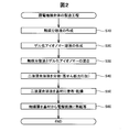
- FIG. 2 is a flowchart showing the procedure of the manufacturing process of the membrane electrode assembly 5.
- step S10 a catalyst dispersion is prepared.
- FIG. 3 is an explanatory diagram for explaining the step of preparing the catalyst dispersion (step S10).
- Step S10 includes two steps S12 and S14.
- step S12 the material of the catalyst dispersion is mixed. Specifically, ion exchange water is added to the carbon carrying the catalyst metal.
- the catalyst metal for example, platinum or an alloy of platinum and another metal can be used.
- carbon carrying a catalyst metal is referred to as “catalyst carrying particles”, and ion-exchanged water is simply referred to as “water”.
- a hydrophilic solvent such as ethanol or 1-propanol (hereinafter referred to as “solvent”) is added.
- solvent a hydrophilic solvent
- ionomer functions as a surfactant for promoting dispersion of the catalyst-carrying particles.
- the ionomer solution may be added to the dispersed aqueous solution of the catalyst-carrying particles before the hydrophilic solvent is added.
- step S14 a mixture of catalyst-carrying particles, water, a solvent, and an ionomer is dispersed using ultrasonic waves or a bead mill.
- the mixture of the catalyst-carrying particles, water, solvent, and ionomer can be made into fine particles and uniformly dispersed.
- step S20 of FIG. 2 a gelled ionomer solution is prepared.
- FIG. 4 is an explanatory view for explaining the step of producing a gelled ionomer solution (step S20).
- Step S20 includes four steps S22, S24, S26, and S28.
- step S22 an ionomer and a solvent such as alcohol (for example, a mixed solvent of ethanol and 1-propanol) are mixed and stirred.
- step S24 the mixed solution of the ionomer and the solvent is concentrated by evaporating the solvent until the mass percentage of the ionomer becomes 40 to 50 wt%.
- step S26 alcohol or the like is added to lower the mass percentage of the solid content in the gelled ionomer solution.
- step S28 the gelled ionomer solution is heated to 70 to 90 ° C. and held for a predetermined time.
- the ionomer contains water.
- the literature value for the SP value of water is as large as 23.4 at 25 ° C.
- the SP value is a solubility parameter.
- the SP value of the solvent component of the gelled ionomer solution is desired to be 12.3 or less.
- water and alcohol are mixed, water and alcohol are both reduced from the solvent component of the gelled ionomer solution, alcohol is then added, and the SP value of the solvent component of the gelled ionomer solution is lowered. Yes.
- Step S30 of FIG. 2 the gelled ionomer solution is added to the catalyst dispersion and stirred gently.
- a mixed solution of the catalyst dispersion and the gelled ionomer solution is called a two-component mixed solution.
- step S40 a high shear force is applied to the two-component mixed solution to disperse the two-component mixed solution, thereby producing a catalyst ink.
- step S50 a catalyst layer is formed by applying and drying the catalyst ink produced by the processes up to step S40 on the substrate.
- step S60 the catalyst layer is thermally transferred from the base material to each surface of the electrolyte membrane 1 to form the first electrode catalyst layer 2 and the second electrode catalyst layer 3, and the membrane electrode assembly 5 is manufactured. To do.
- a catalyst dispersion was prepared by adding about 20 to 20 wt% of ethanol of about a mass and SS900C / 10 manufactured by Asahi Kasei Co., Ltd. as an ionomer with respect to the mass of the catalyst-carrying particles and stirring sufficiently.
- Step S20 Preparation of gelled ionomer solution> SS900C / 10 manufactured by Asahi Kasei Co., Ltd. was used as the ionomer, and ethanol and 1-propanol (hereinafter referred to as “alcohol etc.”) were added and stirred as solvents. Thereafter, the solvent was evaporated until the mass percentage of SS900C / 10 was 40 to 50 wt%, and alcohol or the like was added again. When the solvent is evaporated, the water in the ionomer is also evaporated. The temperature at which the solvent is evaporated may not be the azeotropic temperature of alcohol and water.
- Step S30 Mixing and stirring of catalyst dispersion and gelled ionomer solution>
- the gelled ionomer solution was mixed with the catalyst dispersion.
- the gelled ionomer solution added to the catalyst dispersion is preferably in an amount of 50 to 70 wt% in terms of mass percent with respect to the mass of the catalyst-supporting particles.
- the helical stirring blade was rotated within a range of 50 to 200 rpm to stir for 1 to 2 hours, and a low shear force was applied.
- Step S40 Dispersion of two-component mixed solution> A catalyst ink was obtained by applying a high shear force to the two-component mixed solution at a peripheral speed of 10 m / s for about 5 minutes using a Philmix 56-50 model manufactured by Plymix.
- Step S60 Transfer of Catalyst Layer to Electrolyte Membrane>
- the catalyst layer was transferred from the film base material and bonded to both surfaces of the Nafion 112 thin film by hot pressing at 130 ° C.
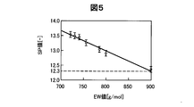
- FIG. 5 is a graph showing the relationship between the EW of an ionomer and the SP value of the solvent component of the gelled ionomer solution when the storage elastic modulus of the gelled ionomer solution is 150 Pa or more.
- the EW value is an ion exchange equivalent, and is a dry mass of ionomer per 1 mol of ion exchange groups (sulfonic acid groups in the present embodiment).
- a large EW value means that the number of sulfonic acid groups per unit weight of ionomer is small.
- the catalyst electrode When the catalyst electrode is formed from a catalyst ink using an ionomer having a small EW value, the mobility of moisture in the catalyst electrode is lowered, and the possibility that the power generation performance is lowered is increased.
- an ionomer having a small EW value is easily dissolved in hot water (for example, water having a temperature of 80 ° C. or higher)
- the catalyst electrode formed by the catalyst ink using the ionomer having a small EW value is not located inside the fuel cell in operation. There is a possibility that the durability against a hot and humid environment will be lowered. Therefore, it is preferable to use an ionomer having a large EW value.
- an ionomer having an EW value larger than 900 g / mol there is a problem that it is difficult to increase the viscosity of the gelled ionomer solution.
- Viscoelasticity is defined by the response of stress when sinusoidal strain is input to a viscoelastic body.
- the complex elastic modulus is represented by a complex number, the real part is called the storage elastic modulus and the imaginary part is called the loss elastic modulus.
- the storage elastic modulus of the gelled ionomer solution is measured by applying a vibration at a frequency of 1 Hz and measuring the value when the strain amount is 1% by a dynamic viscoelasticity measuring device manufactured by Anton Paar. Got. Note that PP25 manufactured by Anton Paar was used as the type of plate used in the dynamic viscoelasticity measuring apparatus manufactured by Anton Paar.
- the reason for setting the storage elastic modulus judgment criterion to 150 Pa is as follows.
- a catalyst ink is formed using a gelled ionomer solution having a storage modulus of less than 150 Pa, sufficient coating strength cannot be obtained in the catalyst ink application step, and the possibility of deterioration of the catalyst electrode increases. Because.
- the SP value of the solvent component of the gelled ionomer solution can be adjusted by adjusting the type and mixing ratio of the solvent added to the ionomer.
- the SP value of ethanol in a standard state 25 ° C., 1 atm
- the SP value of 1-propanol is 11.97. Therefore, it is possible to adjust the SP value of the solvent by changing the mixing ratio of ethanol and 1-propanol.
- the SP value should be 12.3 or less in consideration of the amount of water of the solvent component of the gelled ionomer solution. It is preferable to calculate the amount of ethanol and 1-propanol to be added.
- the content ratio of ethanol, 1-propanol, and water in the solvent component of the gelled ionomer solution is quantitatively analyzed, and the weighted average is calculated using the theoretical value of the SP value. It is possible to obtain the SP value of the solvent component of the ionized ionomer solution.
- FIG. 5 shows that there is a significant relationship between the EW value and the SP value necessary for setting the storage elastic modulus to 150 Pa or more.
- the storage elastic modulus is 150 Pa or more when the SP value is 12.3 or less.
- the SP value of ethanol is 12.92, which is greater than 12.3.
- the SP value of 1-propanol is 11.97, which is smaller than 12.3. Therefore, with respect to the amount of alcohol added when preparing the SP value of the solvent component of the gelled ionomer solution, the SP value can be reduced to 12.3 or less by decreasing the ethanol ratio and increasing the 1-propanol ratio. Is possible.
- the target SP value may be smaller than 12.3.
- FIG. 6 shows the mass percent solids in the gelled ionomer solution and the storage elastic modulus when an ionomer having an EW value of 900 is used and the SP value of the solvent component of the gelled ionomer solution is 12.3. It is explanatory drawing which shows a relationship. As can be seen from FIG. 6, in terms of the average value, when the mass percentage of the solid content in the gelled ionomer solution is 17.5 wt% or more, the storage elastic modulus is 150 Pa or more. Further, in consideration of variation, if the mass percentage of the solid content in the gelled ionomer solution is 20 wt% or more, the storage elastic modulus can be 150 Pa or more.
- the mass percentage of the solid content in the gelled ionomer solution is preferably 17.5 wt% to 25 wt%, and more preferably 20 wt% to 25 wt%.
- the weight percent solids in the gelled ionomer solution may be greater than 25 wt%.
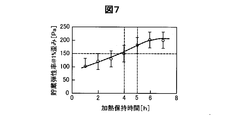
- FIG. 7 shows the heat retention when an ionomer having an EW value of 900 is used, the SP value of the solvent component of the gelled ionomer solution is 12.3, and the mass percentage of the solid content in the gelled ionomer solution is 20 wt%.
- the storage elastic modulus can be 150 Pa or more if the heating and holding time is 4 hours or more. Further, in consideration of variation, when the heating and holding time is 5 hours or more, the storage elastic modulus can be 150 Pa or more. Even when the heating and holding time is 6 to 7 hours or more, the storage elastic modulus is unlikely to be higher than about 200 Pa. A shorter heating and holding time is advantageous from the viewpoint of manufacturing cost. Therefore, the heating and holding time is preferably 4 to 7 hours, and more preferably 5 to 6 hours.
- the SP value of the solvent component when preparing the gelled ionomer solution is 12.3, even when the EW value of the ionomer is 900 g / mol, storage of the gelled ionomer solution is performed.
- the elastic modulus can be adjusted to 150 Pa or more.
- an ionomer having an EW value of 900 is used, and the mass percentage of the solid content in the gelled ionomer solution when the SP value of the solvent component of the gelled ionomer solution is 12.3 is 17. Since the content is 5 wt% to 25 wt%, the storage elastic modulus of the gelled ionomer solution can be adjusted to 150 Pa or more. The mass percentage of the solid content in the gelled ionomer solution is more preferably 20 wt% to 25 wt%. Even if the EW value of the ionomer varies, the storage elastic modulus of the gelled ionomer solution can be adjusted to 150 Pa or more.
- the SP value of the solvent component of the gelled ionomer solution is 12.3, and the mass percentage of the solid content in the gelled ionomer solution is 20 wt%. Since the heating and holding time is 4 to 7 hours, the storage elastic modulus of the gelled ionomer solution can be adjusted to 150 Pa or more. The heating and holding time of the gelled ionomer solution is more preferably 5 to 6 hours. Even if the EW value of the ionomer varies, the storage elastic modulus of the gelled ionomer solution can be adjusted to 150 Pa or more.
- the SP value of the solvent component of the gelled ionomer solution is 12.3, but the SP value is not limited to 12.3.
- the gelled ionomer solution is concentrated to reduce the SP value of the solvent component of the gelled ionomer solution by reducing the water with a large SP value contained in the ionomer. Is possible.
- the storage elastic modulus of the gelled ionomer solution can be adjusted to 150 Pa or more more easily than preparing other parameters.
Landscapes
- Chemical & Material Sciences (AREA)
- Engineering & Computer Science (AREA)
- Chemical Kinetics & Catalysis (AREA)
- General Chemical & Material Sciences (AREA)
- Electrochemistry (AREA)
- Manufacturing & Machinery (AREA)
- Life Sciences & Earth Sciences (AREA)
- Materials Engineering (AREA)
- Organic Chemistry (AREA)
- Wood Science & Technology (AREA)
- Thermal Sciences (AREA)
- Physics & Mathematics (AREA)
- Inert Electrodes (AREA)
- Fuel Cell (AREA)
- Sustainable Development (AREA)
- Sustainable Energy (AREA)
- Catalysts (AREA)
Abstract
Description
δ=√((ΔH―RT)/V)
で定義される。ここで、ΔHは、標準状態のモル蒸発エンタルピー、Rは気体定数、Tは絶対温度(25℃=293.15k)、Vは標準状態のモル体積、である。本実施形態では、後述するように、ゲル化アイオノマー溶液の溶媒成分のSP値を12.3以下としたい。しかし、SP値の大きな水の影響のため、ゲル化アイオノマー溶液の溶媒成分のSP値を下げにくい。本実施形態では、水とアルコール等と混合し、ゲル化アイオノマー溶液の溶媒成分から水とアルコールとをともに減少させ、その後アルコール等を加えて、ゲル化アイオノマー溶液の溶媒成分のSP値を下げている。
<ステップS10:触媒分散液の調製>
白金コバルト合金からなる触媒を担持したカーボン粒子(触媒担持粒子)に、触媒担持粒子の質量の1~5倍程度の質量のイオン交換水を加え、さらに、触媒担持粒子の質量の3~5倍程度の質量のエタノールと、アイオノマーとして旭化成(株)製のSS900C/10を、触媒担持粒子の質量に対して10~20wt%加えて、十分に撹拌することにより、触媒分散液を調製した。
アイオノマーとして旭化成(株)製のSS900C/10を用い、これに溶媒としてエタノールと1-プロパノール(以下「アルコール等」と呼ぶ。)を加えて撹拌した。その後、SS900C/10の質量パーセントが、40~50wt%となるまで、溶媒を蒸発させた後、再びアルコール等を加えた。なお、溶媒を蒸発させるときには、アイオノマー中の水も蒸発する。なお、溶媒を蒸発させるときときの温度は、アルコールと水との共沸温度でなくてもよい。
触媒分散液に、ゲル化アイオノマー溶液を混合した。触媒分散液に加えられるゲル化アイオノマー溶液は、触媒担持粒子の質量に対して、質量パーセントで50~70wt%の量であることが好ましい。その後、ヘリカル形状の撹拌羽根を回転速度50~200rpmの範囲内で回転させることにより1~2時間撹拌し、低せん断力を印加した。
二液混合溶液に対して、プライミックス社製のフィルミックス56-50型を用いて、周速:10m/sで、約5分間、高せん断力を印加することにより、触媒インクを得た。
上記工程によって得られた各触媒インクを、ドクターブレード式のアプリケータによって、テフロン(登録商標)のフィルム基材上に塗布し、100℃で加熱して乾燥させることにより触媒層を作製した。
ナフィオン112の薄膜の両面に、上記の触媒層を130℃のホットプレスにより、フィルム基材から転写して接合した。
図5は、アイオノマーのEWと、ゲル化アイオノマー溶液の貯蔵弾性率が150Pa以上となるときのゲル化アイオノマー溶液の溶媒成分のSP値と、の関係を示すグラフである。EW値とは、イオン交換当量であり、イオン交換基(本実施形態では、スルホン酸基)1mol当たりのアイオノマーの乾燥質量である。EW値が大きいということは、アイオノマー単位重量当たりのスルホン酸基の数が少ないことを意味する。EW値が小さいアイオノマーを用いた触媒インクにより触媒電極を形成すると、触媒電極における水分の移動性が低下し、発電性能が低下する可能性が高くなる。また、EW値が小さいアイオノマーは熱水(例えば、80℃以上の水)に溶けやすいため、EW値が小さいアイオノマーを用いた触媒インクにより形成された触媒電極は、運転中の燃料電池内部のような高温多湿の環境に対する耐久性が低下してしまう可能性がある。そのため、EW値の大きなアイオノマーを用いることが好ましい。一方、EW値が900g/molより大きいアイオノマーを用いると、ゲル化アイオノマー溶液を増粘させることが困難となるという問題があった。
2…第1の電極触媒層
3…第2の電極触媒層
5…膜電極接合体
7…第1のセパレータ
8…第2のセパレータ
9…流路溝
10…単セル
100…燃料電池
112…ナフィオン
Claims (9)
- 燃料電池用の触媒インクの製造方法であって、
(i)電極触媒と、水と、アルコールと、を混合して触媒分散液を作製する工程と、
(ii)アイオノマーと、溶媒とを混合してゲル化アイオノマー溶液を作製する工程と、
(iii)前記触媒分散液と、前記ゲル化アイオノマー溶液とを混合して触媒インクを製造する工程と、
を備え、
前記工程(ii)において、前記ゲル化アイオノマー溶液を濃縮する濃縮工程を含む、燃料電池用の触媒インクの製造方法。 - 請求項1に記載の燃料電池用の触媒インクの製造方法において、
前記工程(ii)において、前記ゲル化アイオノマー溶液は、固形成分と溶媒成分とを含んでおり、
前記濃縮工程は、前記溶媒成分の溶解度パラメーター(SP値)を12.3以下に調製する工程を含む、燃料電池用の触媒インクの製造方法。 - 請求項1または2に記載の燃料電池用の触媒インクの製造方法において、
前記濃縮工程は、前記ゲル化アイオノマー溶液中の前記アイオノマーの質量パーセントを40~50%に濃縮する濃縮工程を含む、燃料電池用の触媒インクの製造方法。 - 請求項1~3のいずれか一項に記載の燃料電池用の触媒インクの製造方法において、
前記濃縮工程後、アルコールを加えて、前記ゲル化アイオノマー溶液中の固形分の質量パーセントを17.5wt%以上25wt%以下とする工程を備える、燃料電池用の触媒インクの製造方法。 - 請求項1~3のいずれか一項に記載の燃料電池用の触媒インクの製造方法において、おいて、
前記濃縮工程後、アルコールを加えて、前記ゲル化アイオノマー溶液中の固形分の質量パーセントを20wt%以上25wt%以下とする工程を備える、燃料電池用の触媒インクの製造方法。 - 請求項4または5に記載の燃料電池用の触媒インクの製造方法において、さらに、
前記ゲル化アイオノマー溶液を70℃~90℃の温度で4時間以上保持する工程を備える、燃料電池用の触媒インクの製造方法。 - 請求項6に記載の燃料電池用の触媒インクの製造方法において、
前記ゲル化アイオノマー溶液を70℃~90℃の温度で保持する時間は5時間以上である、燃料電池用の触媒インクの製造方法。 - 燃料電池用の触媒層の製造方法であって、
請求項1~7のいずれか一項に記載の製造方法により製造された燃料電池用の触媒インクを基材に塗布する工程と、
前記燃料電池用の触媒インクを加熱して乾燥させる工程と、
を備える、燃料電池用の触媒層の製造方法。 - 燃料電池用の膜電極接合体の製造方法であって、
請求項8に記載の製造方法により製造された燃料電池用の触媒層を、温度130℃のホットプレスにより前記基材から電解質膜に転写する工程を有する、燃料電池用の膜電極接合体の製造方法。
Priority Applications (4)
| Application Number | Priority Date | Filing Date | Title |
|---|---|---|---|
| DE112014001659.4T DE112014001659B9 (de) | 2013-03-28 | 2014-01-14 | Produktionsverfahren für eine Brennstoffzellenkatalysatortinte, Herstellungsverfahren für eine Brennstoffzellenkatalysatorschicht und Herstellungsverfahren für eine Membranelektrodenanordnung für eine Brennstoffzelle |
| US14/779,409 US9819030B2 (en) | 2013-03-28 | 2014-01-14 | Production method of catalyst ink for fuel cell, manufacturing method of catalyst layer for fuel cell and manufacturing method of membrane electrode assembly for fuel cell |
| CN201480018540.0A CN105103350B (zh) | 2013-03-28 | 2014-01-14 | 燃料电池用的催化剂油墨的制造方法、燃料电池用的催化剂层的制造方法、燃料电池用的膜电极接合体的制造方法 |
| KR1020157026443A KR101714950B1 (ko) | 2013-03-28 | 2014-01-14 | 연료 전지용의 촉매 잉크의 제조 방법, 연료 전지용의 촉매층의 제조 방법, 연료 전지용의 막 전극 접합체의 제조 방법 |
Applications Claiming Priority (2)
| Application Number | Priority Date | Filing Date | Title |
|---|---|---|---|
| JP2013-067865 | 2013-03-28 | ||
| JP2013067865A JP5807654B2 (ja) | 2013-03-28 | 2013-03-28 | 燃料電池用の触媒インクの製造方法、燃料電池用の触媒層の製造方法、燃料電池用の膜電極接合体の製造方法 |
Publications (1)
| Publication Number | Publication Date |
|---|---|
| WO2014155901A1 true WO2014155901A1 (ja) | 2014-10-02 |
Family
ID=51622929
Family Applications (1)
| Application Number | Title | Priority Date | Filing Date |
|---|---|---|---|
| PCT/JP2014/000116 Ceased WO2014155901A1 (ja) | 2013-03-28 | 2014-01-14 | 燃料電池用の触媒インクの製造方法、燃料電池用の触媒層の製造方法、燃料電池用の膜電極接合体の製造方法 |
Country Status (6)
| Country | Link |
|---|---|
| US (1) | US9819030B2 (ja) |
| JP (1) | JP5807654B2 (ja) |
| KR (1) | KR101714950B1 (ja) |
| CN (1) | CN105103350B (ja) |
| DE (1) | DE112014001659B9 (ja) |
| WO (1) | WO2014155901A1 (ja) |
Cited By (2)
| Publication number | Priority date | Publication date | Assignee | Title |
|---|---|---|---|---|
| JP2019087306A (ja) * | 2017-11-01 | 2019-06-06 | 凸版印刷株式会社 | 触媒インク及びその製造方法 |
| CN114188582A (zh) * | 2021-12-10 | 2022-03-15 | 东方电气(成都)氢燃料电池科技有限公司 | 一种燃料电池膜电极离聚物预处理方法 |
Families Citing this family (8)
| Publication number | Priority date | Publication date | Assignee | Title |
|---|---|---|---|---|
| JP6206371B2 (ja) | 2014-10-14 | 2017-10-04 | トヨタ自動車株式会社 | 燃料電池用電極触媒層の製造方法 |
| JP6295940B2 (ja) * | 2014-12-12 | 2018-03-20 | トヨタ自動車株式会社 | 触媒インクの製造方法 |
| JP2017142931A (ja) * | 2016-02-09 | 2017-08-17 | トヨタ自動車株式会社 | 燃料電池用電極触媒インクの添加溶媒の選定方法 |
| CN112310420A (zh) * | 2019-07-29 | 2021-02-02 | 上海济平新能源科技有限公司 | 燃料电池用电极、膜电极组件、芯片、催化剂层、催化剂分散液及其制备方法 |
| CN113488667B (zh) * | 2021-06-30 | 2022-11-18 | 同济大学 | 一种通过介电常数来调控离聚物分散状态的方法 |
| CN115966707B (zh) * | 2022-12-28 | 2025-10-21 | 鸿基创能科技(佛山)有限公司 | 一种催化剂涂布膜及其制备方法与应用 |
| CN117026288B (zh) * | 2023-07-19 | 2025-01-28 | 武汉理工大学 | 具有均匀网络结构的spe电解水阳极催化层、制备方法与膜电极 |
| JP7793662B2 (ja) * | 2024-02-13 | 2026-01-05 | 本田技研工業株式会社 | インク及びインク製造方法 |
Citations (6)
| Publication number | Priority date | Publication date | Assignee | Title |
|---|---|---|---|---|
| JP2010531533A (ja) * | 2007-06-25 | 2010-09-24 | ハンファ ケミカル コーポレーション | 燃料電池用触媒インク及びこれを利用した膜−電極複合体の製造方法 |
| JP2010225585A (ja) * | 2009-02-26 | 2010-10-07 | Asahi Kasei E-Materials Corp | 燃料電池用電極触媒層、膜電極接合体及び固体高分子型燃料電池。 |
| JP2010257929A (ja) * | 2009-03-31 | 2010-11-11 | Eneos Celltech Co Ltd | 燃料電池用電極触媒スラリーの製造方法ならびに固体高分子型燃料電池用の電極および膜・電極接合体 |
| WO2011083842A1 (ja) * | 2010-01-07 | 2011-07-14 | 株式会社エクォス・リサーチ | 燃料電池用触媒層の製造装置、燃料電池用触媒層の製造方法、高分子電解質溶液及び高分子電解質溶液の製造方法 |
| JP2012212523A (ja) * | 2011-03-30 | 2012-11-01 | Asahi Kasei E-Materials Corp | 膜電極複合体、及び固体高分子電解質型燃料電池 |
| WO2013031060A1 (ja) * | 2011-08-31 | 2013-03-07 | トヨタ自動車株式会社 | 触媒インクの製造方法、および、燃料電池の製造方法、燃料電池 |
Family Cites Families (9)
| Publication number | Priority date | Publication date | Assignee | Title |
|---|---|---|---|---|
| DE19812592B4 (de) * | 1998-03-23 | 2004-05-13 | Umicore Ag & Co.Kg | Membran-Elektroden-Einheit für Polymer-Elektrolyt-Brennstoffzellen, Verfahren zu ihrer Herstellung sowie Tinte |
| JP3614077B2 (ja) | 2000-03-22 | 2005-01-26 | トヨタ自動車株式会社 | 燃料電池用の電極触媒溶液およびその製造方法 |
| WO2002003489A1 (en) * | 2000-07-03 | 2002-01-10 | Matsushita Electric Industrial Co., Ltd. | Polyelectrolyte fuel cell |
| DE10037072A1 (de) * | 2000-07-29 | 2002-02-14 | Omg Ag & Co Kg | Membran-Elektrodeneinheit für Polymerelektrolyt-Brennstoffzellen und Verfahren zu ihrer Herstellung |
| US7867669B2 (en) * | 2004-09-28 | 2011-01-11 | Giner Electrochemical Systems, Llc | Solid polymer electrolyte composite membrane comprising laser micromachined porous support |
| TWI543201B (zh) * | 2005-02-15 | 2016-07-21 | 東麗股份有限公司 | 高分子電解質成形體、高分子電解質零件、膜電極複合體及高分子電解質型燃料電池 |
| JP5196988B2 (ja) * | 2007-12-21 | 2013-05-15 | スリーエム イノベイティブ プロパティズ カンパニー | インク組成物、その製造方法、そのインク組成物を用いて形成した電極触媒層及びこれらの用途 |
| JP2011159517A (ja) | 2010-02-02 | 2011-08-18 | Toyota Motor Corp | 燃料電池触媒層の製造方法 |
| JP5880562B2 (ja) | 2011-08-31 | 2016-03-09 | トヨタ自動車株式会社 | 触媒インクの製造方法、および、燃料電池の製造方法、燃料電池 |
-
2013
- 2013-03-28 JP JP2013067865A patent/JP5807654B2/ja active Active
-
2014
- 2014-01-14 KR KR1020157026443A patent/KR101714950B1/ko not_active Expired - Fee Related
- 2014-01-14 DE DE112014001659.4T patent/DE112014001659B9/de not_active Expired - Fee Related
- 2014-01-14 US US14/779,409 patent/US9819030B2/en active Active
- 2014-01-14 CN CN201480018540.0A patent/CN105103350B/zh not_active Expired - Fee Related
- 2014-01-14 WO PCT/JP2014/000116 patent/WO2014155901A1/ja not_active Ceased
Patent Citations (6)
| Publication number | Priority date | Publication date | Assignee | Title |
|---|---|---|---|---|
| JP2010531533A (ja) * | 2007-06-25 | 2010-09-24 | ハンファ ケミカル コーポレーション | 燃料電池用触媒インク及びこれを利用した膜−電極複合体の製造方法 |
| JP2010225585A (ja) * | 2009-02-26 | 2010-10-07 | Asahi Kasei E-Materials Corp | 燃料電池用電極触媒層、膜電極接合体及び固体高分子型燃料電池。 |
| JP2010257929A (ja) * | 2009-03-31 | 2010-11-11 | Eneos Celltech Co Ltd | 燃料電池用電極触媒スラリーの製造方法ならびに固体高分子型燃料電池用の電極および膜・電極接合体 |
| WO2011083842A1 (ja) * | 2010-01-07 | 2011-07-14 | 株式会社エクォス・リサーチ | 燃料電池用触媒層の製造装置、燃料電池用触媒層の製造方法、高分子電解質溶液及び高分子電解質溶液の製造方法 |
| JP2012212523A (ja) * | 2011-03-30 | 2012-11-01 | Asahi Kasei E-Materials Corp | 膜電極複合体、及び固体高分子電解質型燃料電池 |
| WO2013031060A1 (ja) * | 2011-08-31 | 2013-03-07 | トヨタ自動車株式会社 | 触媒インクの製造方法、および、燃料電池の製造方法、燃料電池 |
Cited By (3)
| Publication number | Priority date | Publication date | Assignee | Title |
|---|---|---|---|---|
| JP2019087306A (ja) * | 2017-11-01 | 2019-06-06 | 凸版印刷株式会社 | 触媒インク及びその製造方法 |
| JP7020061B2 (ja) | 2017-11-01 | 2022-02-16 | 凸版印刷株式会社 | 触媒インク |
| CN114188582A (zh) * | 2021-12-10 | 2022-03-15 | 东方电气(成都)氢燃料电池科技有限公司 | 一种燃料电池膜电极离聚物预处理方法 |
Also Published As
| Publication number | Publication date |
|---|---|
| DE112014001659B4 (de) | 2019-01-10 |
| US9819030B2 (en) | 2017-11-14 |
| CN105103350A (zh) | 2015-11-25 |
| DE112014001659T5 (de) | 2015-12-10 |
| JP2014192070A (ja) | 2014-10-06 |
| KR20150123873A (ko) | 2015-11-04 |
| US20160056476A1 (en) | 2016-02-25 |
| JP5807654B2 (ja) | 2015-11-10 |
| CN105103350B (zh) | 2017-06-23 |
| DE112014001659B9 (de) | 2019-03-07 |
| KR101714950B1 (ko) | 2017-03-09 |
Similar Documents
| Publication | Publication Date | Title |
|---|---|---|
| JP5807654B2 (ja) | 燃料電池用の触媒インクの製造方法、燃料電池用の触媒層の製造方法、燃料電池用の膜電極接合体の製造方法 | |
| US20040107869A1 (en) | Catalyst ink | |
| Liang et al. | Development of membrane electrode assembly for high temperature proton exchange membrane fuel cell by catalyst coating membrane method | |
| CN106104884A (zh) | 用于燃料电池的催化剂层及其制备方法 | |
| Choi et al. | Optimization of hydrophobic additives content in microporous layer for air breathing PEMFC | |
| CN109860636A (zh) | 一种改进质子交换膜燃料电池性能的催化层的制备方法 | |
| JP6819688B2 (ja) | 膜−電極接合体の製造方法、これから製造された膜−電極接合体およびこれを含む燃料電池 | |
| JP6160591B2 (ja) | 触媒電極層、膜電極接合体、および、燃料電池 | |
| JP6459429B2 (ja) | 固体高分子形燃料電池用電極触媒層を形成する触媒インク、及び固体高分子形燃料電池の製造方法 | |
| JP4987857B2 (ja) | 重合体分散物及び電気触媒インク | |
| Su et al. | High-performance and durable membrane electrode assemblies for high-temperature polymer electrolyte membrane fuel cells | |
| JP5880562B2 (ja) | 触媒インクの製造方法、および、燃料電池の製造方法、燃料電池 | |
| JP7207023B2 (ja) | 触媒インク及び触媒層 | |
| CN105591140B (zh) | 凝胶状电解质的分散液的制造方法 | |
| JP2018116870A (ja) | 触媒インクの製造方法 | |
| JP5915517B2 (ja) | 燃料電池電極の製造方法 | |
| JP2020177734A (ja) | 燃料電池用電極触媒層の製造方法 | |
| JP2011023170A (ja) | 燃料電池用電極の製造方法 | |
| JP7093665B2 (ja) | 高分子電解質薄膜 | |
| Latorrata et al. | Analysis of degradation mechanisms and durability assessment of graphene-based MPLs for PEM fuel cells | |
| KR20230039229A (ko) | 고분자전해질 수전해 수소발생전극 및 이의 제조방법 | |
| Villacorta et al. | Development and Characterization of Gas Diffusion Layer Fabricated Using Carbon Slurry with Ammonium Lauryl Sulfate for Proton Exchange Member Fuel Cells | |
| Parthasarathy et al. | Bio-inspired catalyst compositions for enhanced oxygen reduction using nanostructured Pt electrocatalysts in polymer electrolyte fuel cells | |
| Hassoun et al. | Acid–gel-immobilized, nanoporous composite, protonic membranes as low cost system for Direct Methanol Fuel Cells | |
| Latorrata et al. | Development of accelerated stress tests to assess durability of FEP-and carbon nanotubes-based gas diffusion media for PEM fuel cells |
Legal Events
| Date | Code | Title | Description |
|---|---|---|---|
| WWE | Wipo information: entry into national phase |
Ref document number: 201480018540.0 Country of ref document: CN |
|
| 121 | Ep: the epo has been informed by wipo that ep was designated in this application |
Ref document number: 14773165 Country of ref document: EP Kind code of ref document: A1 |
|
| WWE | Wipo information: entry into national phase |
Ref document number: 14779409 Country of ref document: US |
|
| ENP | Entry into the national phase |
Ref document number: 20157026443 Country of ref document: KR Kind code of ref document: A |
|
| WWE | Wipo information: entry into national phase |
Ref document number: 112014001659 Country of ref document: DE Ref document number: 1120140016594 Country of ref document: DE |
|
| 122 | Ep: pct application non-entry in european phase |
Ref document number: 14773165 Country of ref document: EP Kind code of ref document: A1 |