WO2014155529A1 - 充放電システムの制御方法、及び充放電システム - Google Patents
充放電システムの制御方法、及び充放電システム Download PDFInfo
- Publication number
- WO2014155529A1 WO2014155529A1 PCT/JP2013/058804 JP2013058804W WO2014155529A1 WO 2014155529 A1 WO2014155529 A1 WO 2014155529A1 JP 2013058804 W JP2013058804 W JP 2013058804W WO 2014155529 A1 WO2014155529 A1 WO 2014155529A1
- Authority
- WO
- WIPO (PCT)
- Prior art keywords
- charge
- discharge
- battery
- control device
- side control
- Prior art date
Links
Images


Classifications
-
- H—ELECTRICITY
- H02—GENERATION; CONVERSION OR DISTRIBUTION OF ELECTRIC POWER
- H02J—CIRCUIT ARRANGEMENTS OR SYSTEMS FOR SUPPLYING OR DISTRIBUTING ELECTRIC POWER; SYSTEMS FOR STORING ELECTRIC ENERGY
- H02J7/00—Circuit arrangements for charging or depolarising batteries or for supplying loads from batteries
- H02J7/007—Regulation of charging or discharging current or voltage
- H02J7/0071—Regulation of charging or discharging current or voltage with a programmable schedule
-
- H—ELECTRICITY
- H02—GENERATION; CONVERSION OR DISTRIBUTION OF ELECTRIC POWER
- H02J—CIRCUIT ARRANGEMENTS OR SYSTEMS FOR SUPPLYING OR DISTRIBUTING ELECTRIC POWER; SYSTEMS FOR STORING ELECTRIC ENERGY
- H02J7/00—Circuit arrangements for charging or depolarising batteries or for supplying loads from batteries
- H02J7/0042—Circuit arrangements for charging or depolarising batteries or for supplying loads from batteries characterised by the mechanical construction
- H02J7/0045—Circuit arrangements for charging or depolarising batteries or for supplying loads from batteries characterised by the mechanical construction concerning the insertion or the connection of the batteries
-
- H—ELECTRICITY
- H01—ELECTRIC ELEMENTS
- H01M—PROCESSES OR MEANS, e.g. BATTERIES, FOR THE DIRECT CONVERSION OF CHEMICAL ENERGY INTO ELECTRICAL ENERGY
- H01M10/00—Secondary cells; Manufacture thereof
- H01M10/42—Methods or arrangements for servicing or maintenance of secondary cells or secondary half-cells
- H01M10/425—Structural combination with electronic components, e.g. electronic circuits integrated to the outside of the casing
- H01M10/4257—Smart batteries, e.g. electronic circuits inside the housing of the cells or batteries
-
- H—ELECTRICITY
- H02—GENERATION; CONVERSION OR DISTRIBUTION OF ELECTRIC POWER
- H02J—CIRCUIT ARRANGEMENTS OR SYSTEMS FOR SUPPLYING OR DISTRIBUTING ELECTRIC POWER; SYSTEMS FOR STORING ELECTRIC ENERGY
- H02J7/00—Circuit arrangements for charging or depolarising batteries or for supplying loads from batteries
- H02J7/00032—Circuit arrangements for charging or depolarising batteries or for supplying loads from batteries characterised by data exchange
- H02J7/00034—Charger exchanging data with an electronic device, i.e. telephone, whose internal battery is under charge
-
- Y—GENERAL TAGGING OF NEW TECHNOLOGICAL DEVELOPMENTS; GENERAL TAGGING OF CROSS-SECTIONAL TECHNOLOGIES SPANNING OVER SEVERAL SECTIONS OF THE IPC; TECHNICAL SUBJECTS COVERED BY FORMER USPC CROSS-REFERENCE ART COLLECTIONS [XRACs] AND DIGESTS
- Y02—TECHNOLOGIES OR APPLICATIONS FOR MITIGATION OR ADAPTATION AGAINST CLIMATE CHANGE
- Y02E—REDUCTION OF GREENHOUSE GAS [GHG] EMISSIONS, RELATED TO ENERGY GENERATION, TRANSMISSION OR DISTRIBUTION
- Y02E60/00—Enabling technologies; Technologies with a potential or indirect contribution to GHG emissions mitigation
- Y02E60/10—Energy storage using batteries
Definitions
- the present invention relates to a charge / discharge system control method including a battery system having a secondary battery and a battery-side control device, and a charger / discharger having a charger-side control device, and a charge / discharge system.
- Patent Document 1 as an example of an electric vehicle charging system, an electric vehicle stores a charging control program indicating a charging pattern for a secondary battery, and an electric vehicle charger supplies charging power to the secondary battery.
- a charging system that communicates with an electric vehicle in advance, receives a charging control program stored in the electric vehicle, stores the charging control program in a charger, and controls charging power according to the charging control program.
- V2H Vehicle to Home
- Patent Document 2 as an example of the V2H system, a charger / discharger equipped with a charge / discharge connector and a secondary battery for a house are installed on the house side, and an inlet part, power conversion that performs AC / DC conversion and DC / AC conversion And a vehicle power system provided with a secondary battery for a vehicle is provided on the electric vehicle side.
- the vehicular power system is connected to the charger / discharger connector via the inlet and receives power supplied from the house. Further, in the event of an emergency such as a power failure, the residential secondary battery and the vehicle secondary battery supply power to the electrical home appliance.
- Patent Document 3 describes, as another example of the V2H system, a charger / discharger connected to system power on the house side and a secondary battery of an electric vehicle connected by a charging paddle.
- commercial power supplied from the power system is converted to high frequency AC, and high frequency AC is supplied to the electric vehicle side by electromagnetic induction.
- high frequency AC is converted to DC and a secondary battery is charged.
- the electric power supply amount is limited to a range obtained by subtracting the electric energy to be secured from the remaining capacity of the secondary battery.
- control between the electric vehicle and a home inverter (hereinafter referred to as an inverter) is performed according to a certain protocol.
- the protocol needs to match at the hardware level and the software level (for example, Patent Documents 2 and 3 above).
- the objective is comprised including the battery system which has a secondary battery and a battery side control apparatus, and the charger / discharger which has a charger side control apparatus.
- charge / discharge control is to be performed reliably.
- the present invention provides a battery system having a secondary battery and a battery-side control device, and outputs DC power by discharging the secondary battery, and converts power supplied from an AC power source to DC.
- a charge / discharge system control method comprising a charger / discharger that converts the battery into a secondary battery and charges the secondary battery, wherein the charger / discharger controls the charge and discharge.
- the charge / discharge control program is a program for performing the charge control and the discharge control, wherein the charge / discharge side control device is communicably connected to the battery side control device and is transmitted from the battery side control device.
- the communication device When the specific information for specifying is received, the communication device is connected to an external server device so as to be communicable, and the charge / discharge control program specified by the specific information is acquired from the server device and acquired. And performing control of the charging and the discharging in accordance with the charge-discharge control program.
- the server device when the charge / discharge side control device receives the specific information specifying the type of the charge / discharge control program from the battery side control device, the server device stores the charge / discharge control program of the type indicated by the received specific information. Therefore, charge / discharge control is performed between the charger / discharger side and the battery system side based on the charge / discharge control program of the type suitable for both. Is called. Therefore, according to the control method of the charge / discharge system of the present invention, the charge / discharge can be reliably controlled between the battery system and the charger / discharger.
- Another aspect of the present invention is a control method for the charge / discharge system, wherein the charge / discharge side control device performs the charge or discharge control according to the acquired charge / discharge control program. Whether the predetermined current value determined by the control program exceeds the maximum current value that can be charged or discharged to the secondary battery, or by the charge or discharge control determined by the charge / discharge control program It is determined whether the temperature of the secondary battery exceeds the allowable upper limit value, and it is determined that the current value does not exceed the maximum current value, or the temperature of the secondary battery does not exceed the allowable upper limit value. When it is determined, the charging or discharging control is started.
- charging or discharging of the secondary battery is controlled based on an appropriate supply current value, and charging or discharging of the secondary battery is controlled while maintaining the temperature of the secondary battery at an appropriate temperature. It can be carried out. In this way, it is possible to efficiently charge the secondary battery and discharge the secondary battery.
- a charging / discharging system control method including a charging / discharging device for charging a battery, wherein the charging / discharging device includes a charging / discharging control device, while the battery system controls the charging and discharging.
- the battery-side control device includes a battery-side control device, and is communicably connected to the charge / discharge-side control device, and performs the charge control and the discharge control transmitted from the charge-discharge side control device.
- the charge / discharge control program specified by the specific information is connected from an external server device so as to be communicable with the external server device. It acquires, and performs control of the charge and the discharge according to the charge-discharge control program acquired.
- the battery side control device when the battery side control device receives information specifying the type of the charge / discharge control program from the charge / discharge side control device, the type of charge / discharge control program indicated by the received specific information is received from the server device. Since charge / discharge control is performed according to the acquired charge / discharge control program, charge / discharge control is performed between the charger / discharger side and the battery system side based on a charge / discharge control program of a type suitable for both. . Therefore, according to the control method of the charge / discharge system of the present invention, the charge / discharge can be reliably controlled between the battery system and the charger / discharger.
- Another aspect of the present invention is a control method for the charge / discharge system, wherein the battery-side control device performs the charge or discharge control according to the acquired charge / discharge control program. Whether the predetermined current value determined by the program exceeds the maximum current value that can be charged or discharged to the secondary battery, or by the charge or discharge control determined by the charge / discharge control program, Determine whether the temperature of the secondary battery exceeds the allowable upper limit value, determine that the current value does not exceed the maximum current value, or determine that the temperature of the secondary battery does not exceed the allowable upper limit value In this case, the charging or discharging is controlled.
- charging or discharging of the secondary battery is controlled based on an appropriate supply current value, and charging or discharging of the secondary battery is controlled while maintaining the temperature of the secondary battery at an appropriate temperature. It can be carried out. In this way, it is possible to efficiently charge the secondary battery and discharge the secondary battery.
- Another aspect of the present invention is a battery system having a secondary battery and a battery-side control device, and outputs DC power by discharging the secondary battery, and converts power supplied from an AC power source to DC.
- a charging / discharging system configured to include a charging / discharging device that supplies the secondary battery, wherein the charging / discharging device includes a charging / discharging side control device that controls the charging and discharging, and Specific information for identifying a charge / discharge control program, which is a program for performing the charge control and the discharge control, which is transmitted from the battery side control device, so that the discharge side control device is communicably connected to the battery side control device. Is received so as to be communicable with an external server device, the charge / discharge control program specified by the specific information is acquired from the server device, and the acquired charge / discharge control program is acquired. And performing control of the charge and the discharge according to.
- a charging / discharging system including a charging / discharging device for charging a battery, wherein the charging / discharging device includes a charging / discharging control device, while the battery system controls the charging and discharging.
- the battery-side control device is a program that is connected to the charge / discharge-side control device so as to be communicable and that is transmitted from the charge / discharge-side control device to perform the charge control and the discharge control.
- the communication apparatus When specific information specifying a charge / discharge control program is received, the communication apparatus is connected to an external server device so as to be communicable, and the charge / discharge control program specified by the specific information is acquired from the server device. Characterized in that according to the acquired charge-discharge control program performs control of the charging and the discharging.
- charging / discharging can be reliably performed in a charging / discharging system including a battery system having a secondary battery and a battery-side control device, and a charger / discharger having a charger-side control device. .
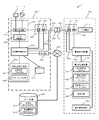
- FIG. 1 is a block diagram illustrating a configuration of a charge / discharge system 1.
- FIG. 3 is a flowchart for explaining processing performed in the charge / discharge system 1; 3 is a flowchart for explaining processing performed in the charge / discharge system 1; 3 is a flowchart for explaining processing performed in the charge / discharge system 1; It is a flowchart explaining the charging / discharging end process. It is a flowchart explaining a battery side termination process.
- 2 is a block diagram illustrating a configuration of a charge / discharge system 2.
- FIG. 5 is a flowchart for explaining processing performed in the charge / discharge system 2; 5 is a flowchart for explaining processing performed in the charge / discharge system 2; 5 is a flowchart for explaining processing performed in the charge / discharge system 2;
- FIG. 1 is a block diagram illustrating a configuration of a charge / discharge system 1 according to the first embodiment.
- the charge / discharge system 1 of the present embodiment includes a battery system 100, a charger / discharger 200 having a power converter 221, and a server device 300.
- the battery system 100 is a system having a secondary battery 110 and a battery-side control device 120, and is an automobile such as an electric car or a plug-in hybrid car.
- the charger / discharger 200 is, for example, a bidirectional inverter provided in a consumer.
- the charger / discharger 200 discharges the secondary battery 110, and converts the power supplied from the AC power supply 4 into DC by the power converter 221 to charge the secondary battery 110.
- the electric power discharged from the secondary battery 110 is supplied to the load 5 (for example, a load in a consumer) via the power converter 221.
- the charger / discharger 200 includes a charge / discharge side control device 210, a power supply unit 220, a charge / discharge side power detection unit 230, a charge / discharge side storage device 240, a communication device 260, and a storage device 270. ing.
- the charge / discharge side control device 210 is a part in charge of control in the charger / discharger 200.
- the charge / discharge side control device 210 includes a CPU, a memory, a communication interface, and the like (all not shown), reads a program stored in the storage device 270 (hereinafter referred to as a charge / discharge control program) into the memory, It works by doing this.
- the charge / discharge control program includes a charge / discharge control procedure (protocol on the charger / discharger side) performed by the charge / discharge side control device 210 and a charge / discharge control procedure (battery side protocol) in the battery side control device 120.
- these protocols depend on the hardware constituting the charger / discharger 200 and the battery system 100 and the software incorporated therein, and the two protocols correspond to (match) each other. Must be. Therefore, if the hardware and software of the charger / discharger 200 or the battery system 100 are different, the charge / discharge control program that operates on them needs to be different.
- the power supply unit 220 is a part to which charging power for charging the secondary battery 110 is output and discharge power from the secondary battery 110 is input, and includes a power converter 221 and a gate control device 222. ing.
- the power converter 221 converts AC power from the AC power source 4 into DC power, and converts DC power sent from the secondary battery 110 into AC power.
- the power converter 221 includes a PWM converter (not shown). This PWM converter controls electric power according to a gate control signal input to the gate terminal.
- the gate control device 222 is a part that generates a gate control signal that is input to the gate terminal of the power converter 221.
- the gate control device 222 is electrically connected to the charge / discharge side control device 210, and the operation is controlled by the charge / discharge side control device 210.
- the charge / discharge side power detection unit 230 includes a voltage conversion unit 231 and a current conversion unit 232, and charging power is supplied to the secondary battery 110, and the power of the secondary battery 110 is discharged in the middle of the power line 251.
- the voltage conversion unit 231 is a part that converts the terminal voltage of the power supply unit 220 (power converter 221) included in the charger / discharger 200 into a voltage having a magnitude suitable for measurement, and is configured by a current limiting resistor, for example.
- the current conversion unit 232 is a part that converts the current flowing through the power supply line 251 into a current and voltage having a magnitude suitable for measurement, and includes, for example, a shunt or a DC current transformer. Outputs from these voltage conversion unit 231 and current conversion unit 232 are input to the charge / discharge side control device 210. And the charging / discharging side control apparatus 210 can recognize the magnitude
- the charge / discharge storage device 240 stores various types of information necessary for charge / discharge.
- the charge / discharge side storage device 240 is constituted by a semiconductor storage device, a magnetic storage device, or an optical storage device, and the stored information is read by the charge / discharge side control device 210.
- the charge / discharge storage device 240 is provided with an initial setting program storage area 241 for storing an initial setting program and a hardware information storage area 242.
- the hardware information storage area 242 has a maximum output of the power converter 221 (represented by a voltage value, a current value, a power value, etc.), a voltage range that can be input to the power converter 221 (hereinafter referred to as these). Is referred to as hardware information).
- the communication device 260 connects the charge / discharge-side control device 210 and the server device 300 to a wired or wireless communication network 350 (for example, wired LAN, wireless LAN, Internet, dedicated line, power line communication (PLC (Power Line Communication), etc.).
- the charge / discharge-side control device 210 is connected to the server device 300 so as to be communicable by controlling the communication device 260.
- the storage device 270 includes, for example, a hard disk, an SSD (Solid State Drive), and the like, and stores the charge / discharge control program acquired from the server device 300.
- the server device 300 includes a CPU, a memory, a communication interface, and a storage device such as an SSD or a hard disk (none of which is shown), and operates according to a program stored in the memory.
- the server apparatus 300 has a charge / discharge control program storage area 311 and a charge / discharge control program number information storage area 312.
- the charge / discharge control program storage area 311 stores at least one charge / discharge control program.
- number information (corresponding to specification information) for specifying the type of each of the charge / discharge control programs stored in the charge / discharge control program storage area 311. (Referred to as discharge control program number information).
- discharge control program number information a number managed by the charge / discharge program number information, in other words, a number stored in the charge / discharge program number information is referred to as a charge / discharge control program number.
- the battery system 100 includes a secondary battery 110, a battery side control device 120, a battery side power detection unit 130, a battery side storage device 140, and a battery information transmission unit 150.
- the secondary battery 110 is a part that stores DC power that is a power source of the battery system 100 and is charged by the charging power supplied from the charger / discharger 200.
- a lithium ion battery is preferably used as the secondary battery 110.
- the battery side control device 120 is a part in charge of control in the battery system 100.
- the battery-side control device 120 includes a CPU, a memory, a communication interface, etc. (all not shown), and operates according to a program stored in the memory.
- the battery-side power detection unit 130 includes a voltage conversion unit 131 and a current conversion unit 132.
- the battery-side power detection unit 130 supplies charging power to the secondary battery 110, and in the middle of the power line 151 where the power of the secondary battery 110 is discharged. Is provided.
- the voltage converter 131 converts the voltage of the power supplied through the power line 151 into a voltage having a magnitude suitable for measurement.
- the voltage conversion unit 131 is configured by, for example, a current limiting resistor.
- the current converter 132 converts the current flowing through the power supply line 151 into a current and voltage having a magnitude suitable for measurement.
- the current converter 132 is configured by, for example, a shunt or a direct current transformer.
- the outputs from the voltage conversion unit 131 and the current conversion unit 132 are input to the battery-side control device 120. Since the outputs of the voltage conversion unit 131 and the current conversion unit 132 indicate voltage and current, the battery-side control device 120 can recognize the magnitude of power based on the outputs of the voltage conversion unit 131 and the current conversion unit 132. .
- a battery-side connector 153 is provided at the end of the power line 151 and the end of the communication line 152 from the battery-side control device 120.
- the battery side connector 153 is a part connected to the charge / discharge side connector 253 of the charger / discharger 200.
- the charging / discharging connector 253 is provided at the ends of the power line 251 and the communication line 252 on the charger / discharger 200 side. For this reason, when the battery side connector 153 and the charge / discharge side connector 253 are connected, the power line 151, the power lines 251, the communication line 152, and the communication lines 252 are electrically connected.
- the battery-side storage device 140 stores various types of information necessary for charging / discharging the secondary battery 110.
- the battery-side storage device 140 uses a semiconductor storage device such as a memory, a magnetic storage device such as a hard disk or an SSD, or an optical storage device such as a CD-ROM, and the stored information is read by the battery-side control device 120. It is.
- the battery-side storage device 140 has an initial setting program storage area 141 in which an initial setting program is stored, a charge / discharge control program number storage area 142, and a charge / discharge pattern sequence number storage in which charge / discharge patterns are stored. An area 143 and a battery information storage area 144 are provided.
- the charge / discharge control program number storage area 142 stores information corresponding to the charge / discharge control program number information stored in the server device 300 (hereinafter referred to as battery-side charge / discharge control program number information). ing. In this embodiment, it is assumed that integer values from “1” to “m” (m is an integer value of 1 or more) are stored as battery-side charge / discharge control program number information.
- the charge / discharge pattern sequence number storage area 143 stores a charge / discharge pattern performed by the charge / discharge control program specified by the charge / discharge control program number.
- a charge / discharge pattern for example, a charge / discharge pattern set to shorten the charge / discharge time by increasing the charge / discharge current, and set to reduce the charge / discharge current instead of increasing the charge / discharge time.
- battery-specific parameters such as a charge start voltage, a discharge start voltage, a charge temperature characteristic, a discharge temperature characteristic, a maximum dischargeable current, and a maximum chargeable current of the secondary battery 110 (hereinafter referred to as battery specific information). Is stored). Further, in the battery information storage area 144, information such as the voltage or current of the secondary battery 110 at the time of charge / discharge and the temperature / voltage of each cell of the secondary battery 110 (hereinafter referred to as battery information at the time of charge / discharge). It is remembered.
- the battery information transmission unit 150 transmits battery specific information and charging / discharging battery information to the charge / discharge control device 210 based on the control of the battery control device 120.
- the outline of the processing performed in the charge / discharge system 1 is as follows. First, when the battery side connector 153 of the battery system 100 and the charge / discharge side connector 253 of the charger / discharger 200 are connected, various initial settings are performed. After completion of the initial setting, the charge / discharge side control device 210 receives battery side charge / discharge control program number information (specific information) transmitted from the battery side control device 120.
- the charge / discharge-side control device 210 When the battery-side charge / discharge control program number information is received, the charge / discharge-side control device 210 is connected to the server device 300 and received from the battery-side control device 120 among the charge / discharge control programs stored in the server device 300. A charge / discharge control program corresponding to the battery side charge / discharge control program number is acquired. The charge / discharge side control device 210 performs charge / discharge control in cooperation with the battery side control device 120 based on the charge / discharge control program.
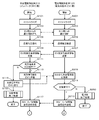
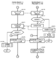
- 2 to 4 are flowcharts for explaining processing performed in the charge / discharge system 1.
- the initial setting program is read from the discharge-side storage device 240 and the battery-side storage device 140. Then, each of the charge / discharge side control device 210 and the battery side control device 120 performs an initialization operation (S101, S201). In this initialization operation, initialization of various setting values, preparation for communication between the charge / discharge side control device 210 and the battery side control device 120, and the like are performed.
- the charge / discharge side control device 210 and the battery side control device 120 are in a state of waiting for communication start (S103, S203).
- negotiation is performed between the charge / discharge side control device 210 and the battery side control device 120, and a communication state is established.
- the charge / discharge side control device 210 transmits notification information indicating that the communication state is established to the battery side control device 120 (S105). This notification information is received by the battery-side control device 120 (S205).
- the battery side control device 120 that has received the notification information transmits EV charge / discharge request information indicating a charge / discharge request to the charger 200 to the charge / discharge side control device 210 (S207).
- the EV charge / discharge request information includes battery specific information.
- the charge / discharge side control device 210 determines whether to accept the charge / discharge request based on the battery specific information (S111). That is, it is determined whether the charger / discharger 200 is in a chargeable / dischargeable state.
- the charge / discharge side control device 210 transmits chargeable / dischargeable information indicating that charging / discharging is possible to the battery side control device 120 (S113). ).
- the charging / discharging control device 210 transmits charging / discharging impossible information indicating that charging / discharging is not possible to the battery control device 120 ( S115), a charge / discharge side termination process is performed (S150), and the series of operations is terminated.
- the battery-side control device 120 When the battery-side control device 120 receives the charge / discharge impossibility information from the charge / discharge-side control device 210 (S209, S211: N), the battery-side termination processing is performed (S250), and the series of operations is terminated. On the other hand, when the chargeable / dischargeable information is received from the charge / discharge side control device 210 (S209, S211: Y), the battery side control device 120 charges / discharges hardware request information for requesting transmission of hardware information. It transmits to the side control apparatus 210 (S213).
- the charge / discharge side control device 210 When receiving the hardware request information (S117), the charge / discharge side control device 210 transmits the hardware information to the battery side control device 120 as shown in FIG. 3 (S119).
- the battery-side control device 120 When the battery-side control device 120 receives the hardware information (S215), the battery-side control device 120 determines whether or not the battery-side control device 120 is compatible with the hardware specification indicated by the hardware information (S217). When not corresponding (S217: N), the battery-side control device 120 transmits notification information indicating that charging / discharging is impossible to the charging / discharging-side control device 210 (S221), and performs battery-side termination processing (S250). ), And a series of operations are terminated.
- the battery-side control device 120 displays notification information indicating that charging / discharging is possible on the charge / discharge side.
- the data is transmitted to the control device 210 (S219), and the counter n is set to “1”. Then, the battery side control device 120 transmits the battery side charge / discharge control program number (for example, “1”) corresponding to the current counter n to the charge / discharge side control device 210 (S223).
- the charge / discharge-side control device 210 When the charge / discharge-side control device 210 receives notification information indicating that charging / discharging is not possible from the battery-side control device 120 (S121, S123: N), the charge / discharge-side control processing is performed (S150). End the operation. On the other hand, when the notification information indicating that charging / discharging is possible (S121, S123: Y), the charging / discharging side control device 210 receives the battery side charging / discharging control program number information from the battery side control device 120. stand by.
- the charge / discharge control device 210 When the charge / discharge control device 210 receives the charge / discharge control program number information from the battery control device 120 (S125), the charge / discharge control device 210 is connected to the server device 300 and acquires (downloads) the charge / discharge control program (S126). Specifically, the charging / discharging control device 210 is connected to the server device 300 and refers to the charging / discharging control program storage area 311 and the charging / discharging program number information storage region 312, and the charging / discharging stored in the server device 300 is stored. Among the discharge control programs, the charge / discharge control program corresponding to the received battery-side charge / discharge control program number (for example, “1”) is downloaded. The charge / discharge side control device 210 stores the downloaded charge / discharge control program in the storage device 270.
- the charge / discharge-side control device 210 determines whether charge / discharge control can be performed by the received charge control program (S127). In this determination, for example, the maximum current value determined by the received charge / discharge control program exceeds the maximum current value that can be supplied to the secondary battery 110 or the maximum current value that can be discharged from the secondary battery 110. In such a case, the charge / discharge-side control device 210 determines that charge control or discharge control cannot be performed. In addition, when charge control or discharge control is performed using the received charge control program, the charge / discharge-side control device 210 cannot perform charge control or discharge control even when the temperature of the secondary battery 110 exceeds the allowable upper limit value. judge.
- the charge / discharge side control device 210 increments the counter n by 1 (S131). Then, the charge / discharge side control device 210 compares the current value of the counter n with m (S133). If the value of the counter n is larger than m (S133: Y), the charge / discharge side end processing is performed (S150). ), A series of processing ends. On the other hand, when the value of the counter n is less than or equal to m (S133: N), the processing from S125 is repeated.
- the charge / discharge side control device 210 receives the charge / discharge control program acquired from the server device 300 and the charge / discharge control program.
- the charge / discharge control program number information corresponding to the discharge control program is transmitted to the battery-side control device 120, and the charge / discharge control program is read into the memory (S129).
- the battery side control device 120 receives the charge / discharge control program and the charge / discharge control program number information transmitted from the charge / discharge side control device 210.
- the received charge / discharge control program is read into the memory (S225).
- the battery-side control device 120 checks whether or not charge / discharge control can be performed using the charge / discharge control program acquired in S219 (S227).
- the battery-side control device 120 When charge / discharge control cannot be performed (S227: N), the battery-side control device 120 increases the value of the counter n by 1 (S229). Then, the battery side control device 120 compares the current value of the counter n with the value of m (S231), and if the value of the counter n is larger than m (S231: Y), the battery side end processing is performed (S250). ), A series of processing ends, and when the value of the counter n is less than or equal to m (S231: N), the processing of S223 is repeated.
- the battery side control device 120 can perform charge / discharge control (S227: Y)
- the battery side control device 120 and the charge / discharge side control device 210 charge the secondary battery 110 according to the charge / discharge control program read into the memory (or (Discharge of power of the secondary battery 110) is performed in cooperation (S301).
- This charging / discharging is performed as follows, for example. That is, the charging / discharging-side control device 210 receives battery information at the time of charging / discharging from the battery-side control device 120 as needed, and the charging current supplied by the charging / discharging control program is supplied (discharged). ), The gate control device 222 and the power converter 221 are controlled to convert AC power from the AC power source 4 into DC power and supply it to the secondary battery 110 (or from the secondary battery 110). DC power is converted into AC power and supplied to the load 5 side). Such charge / discharge between the charge / discharge side control device 210 and the battery side control device 120 is performed according to a charge / discharge pattern defined by the charge / discharge control program.
- the charge / discharge side control device 210 performs a charge / discharge side end process (S150) and ends a series of processes.
- the battery-side control device 120 performs a battery-side termination process (S250) and terminates a series of processes.
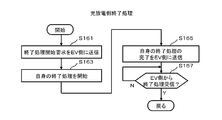
- FIG. 5 is a flowchart for explaining the charge / discharge side termination process.
- the charging / discharging control device 210 transmits a signal requesting the battery control device 120 to end a series of processing (S161) and terminates the processing performed by itself. Is started (S163).
- the charge / discharge-side control device 210 transmits a signal notifying that the end process of itself has been completed to the other side (S165), the charge / discharge side control apparatus 210 notifies the end of the other side transmitted from the other side.
- the reception of the signal is waited (S167: N), and when this signal is received (S167: Y), the charge / discharge-side termination process ends.
- FIG. 6 is a flowchart for explaining the battery-side termination process.
- the battery-side control device 120 transmits a signal requesting to end a series of processing to the charge / discharge-side control device 210 (S261), and ends the processing performed by itself (S261). S263).
- the battery-side control device 120 transmits a signal notifying that its own termination process has been completed to the partner side (S265), a signal notifying that the partner-side termination process has been completed is transmitted from the partner side. Is received (S267: N), and when this signal is received (S267: Y), the battery-side termination process ends.
- the charge / discharge side control device 210 when the charge / discharge side control device 210 receives the specific information specifying the type of the charge / discharge control program from the battery side control device 120, Since the charge / discharge control program of the type indicated by the received information is acquired from the server device 300 and charge / discharge control is performed according to the acquired charge / discharge control program, both the charger / discharger 200 side and the battery system 100 side The charge / discharge control is performed based on a charge / discharge control program of a type adapted to the above. Therefore, according to the charge / discharge system 1 of the present embodiment, charge / discharge control can be reliably performed between the battery system 100 and the charger / discharger 200.
- the charge / discharge control apparatus 210 performs charge or discharge control according to the charge / discharge control program, the predetermined current value determined by the charge / discharge control program does not exceed the maximum current value that can be charged or discharged to the secondary battery 110. Since the charging or discharging control is started when the temperature of the secondary battery 110 does not exceed the allowable upper limit by the charging or discharging control determined by the charging / discharging control program, the charging / discharging-side control device 210 has an appropriate supply current value. Based on the above, charging or discharging of the secondary battery 110 can be controlled, and charging or discharging of the secondary battery 110 can be controlled while maintaining the temperature of the secondary battery 110 at an appropriate temperature. In this way, charging of the secondary battery 110 or discharging of the secondary battery 110 can be performed efficiently.
- FIG. 7 is a block diagram illustrating the configuration of the charge / discharge system 2 according to the second embodiment.
- the battery system 100 is provided with a communication device 170 corresponding to the communication device 260 of the first embodiment.
- the communication device 170 connects the battery-side control device 120 and the server device 300 via a wired or wireless communication network 450 (for example, a wired LAN, a wireless LAN, the Internet, a dedicated line, power line communication (a communication network using a PLC or the like)).
- the battery-side control device 120 is connected to the server device 300 so as to be communicable by controlling the communication device 170.
- the battery system 100 is provided with a storage device 180 corresponding to the storage device 270 of the first embodiment. That is, the storage device 180 includes, for example, a hard disk, an SSD, and the like, and stores a charge / discharge control program acquired from the server device 300.
- the charger / discharger 200 is provided with a charge / discharge control program number storage area 243 corresponding to the charge / discharge control program number storage area 142 of the first embodiment. That is, in the charge / discharge control program number storage area 243, information corresponding to the charge / discharge control program number information stored in the server device 300 (hereinafter referred to as the charger / discharger side charge / discharge control program number information) is stored. ing.
- the charger / discharger side charge / discharge control program number information is information corresponding to the battery side charge / discharge control program number information of the first embodiment.
- the battery information transmission part 150 in 1st Embodiment does not exist.
- Other configurations are the same as those of the first embodiment.
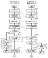
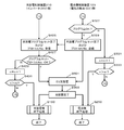
- the outline of the processing performed in the charge / discharge system 2 of the present embodiment is as follows. That is, when the initial setting similar to that of the first embodiment is completed, the battery-side control device 120 transmits the charger / discharger-side charge / discharge control program number information (of the first embodiment) transmitted from the charge / discharge side control device 210. (Corresponding to specific information).
- the battery-side control device 120 When the battery-side control device 120 receives the charger-side charge / discharge control program number information from the charge / discharge-side control device 210, the battery-side control device 120 is connected to the server device 300, and among the charge / discharge control programs stored in the server device 300, A charge / discharge control program corresponding to the charger / discharger side charge / discharge control program number received from the charge / discharge side control device 210 is acquired. Then, the battery side control device 120 performs charge / discharge control in cooperation with the charge / discharge side control device 210 based on the charge / discharge control program.
- the charging / discharging side control apparatus 210 transmits specific information, and is charged / charged.
- the battery-side control device 120 not the discharge-side control device 210 (charger / discharger 200 side), acquires the charge / discharge control program from the server device 300.
- the charging / discharging control apparatus 210 will transmit hardware information (S319).
- the battery-side control device 120 determines whether or not the battery-side control device 120 is compatible with the hardware specification indicated by the hardware information (S417). If not compatible (S417: N), the battery-side control device 120 transmits notification information indicating that charging / discharging is impossible to the charging / discharging-side control device 210 (S421), and the same battery as in the first embodiment.
- a side end process is performed (S250), and a series of operations are ended. Then, the charging / discharging control device 210 receives notification information indicating that charging / discharging is not possible from the battery control device 120 (S321).
- the battery-side control device 120 charges / discharges notification information indicating that charging / discharging is possible. It transmits to the side control apparatus 210 (S419).
- the charge / discharge-side control device 210 receives this notification information and sets the counter n to “1” (S323: Y). Then, the charge / discharge side control device 210 transmits the charger / discharger side charge / discharge control program number information (for example, “1”) corresponding to the current counter n to the battery side control device 120 (S325).
- the battery-side control device 120 waits for reception of the charger / discharger-side charge / discharge control program number information.
- the battery-side control device 120 is connected to the server device 300, Obtain (download) (S326).
- the charge / discharge-side control device 210 is connected to the server device 300 and refers to the charge / discharge control program storage region 311 and the server-side charge / discharge program number information storage region 312, and the server device 300 stores the The charging / discharging control program corresponding to the received charging / discharging device-side charging / discharging control program number is downloaded among the charging / discharging control programs.
- the battery side control device 120 stores the downloaded charge / discharge control program in the storage device 180. And the battery side control apparatus 120 determines whether charging / discharging control can be performed by the received charge control program (S327).
- the maximum current value determined by the received charge / discharge control program is the maximum current value that can be supplied from the charger / discharger 200 to the secondary battery 110 or the maximum current that can be discharged from the secondary battery 110.
- the battery-side control device 120 determines that charge / discharge control cannot be performed.
- the battery-side control device 120 determines that charge / discharge control cannot be performed even when the temperature of the secondary battery 110 exceeds the allowable upper limit value.
- the battery side control device 120 increments the counter n by 1 (S331). Then, the battery-side control device 120 compares the current value of the counter n with m (S333), and if the value of the counter n is larger than m (S333: Y), the battery-side end similar to the first embodiment is performed. Processing is performed (S250), and a series of processing ends. On the other hand, when the value of the counter n is less than or equal to m (S333: N), the process of S325 in FIG. 9 is repeated.
- the battery-side control device 120 When the battery-side control device 120 can perform charge / discharge control by the received charge / discharge control program (S327: Y), the battery-side control device 120 acquires the charge / discharge control program acquired from the server device 300 and the charge / discharge control corresponding thereto.
- the discharger side charge / discharge control program number information is transmitted to the charge / discharge side control device 210 (S329).
- the charge / discharge side control device 210 receives the charge / discharge control program and the charger / discharger side charge / discharge control program number information transmitted from the battery side control device 120.
- the received charge / discharge control program is read into the memory (S425).
- the charge / discharge side control device 210 determines whether or not charge / discharge control can be performed (S427). If the charge / discharge control cannot be performed (S427: N), the charge / discharge side control device 210 sets the value of the counter n. It is increased by 1 (S429).
- the charge / discharge-side control device 210 compares the current value of the counter n with the value of m (S431), and if the value of the counter n is larger than m (S431: Y), the same as in the first embodiment. A charge / discharge side termination process is performed (S150), and a series of processes is terminated. On the other hand, if the value of the counter n is equal to or less than m (S431: N), the process of S423 is repeated.
- the charge / discharge side control device 210 can perform charge / discharge control (S427: Y)
- the charge / discharge side control device 210 and the battery side control device 120 charge the secondary battery 110 according to the charge / discharge control program.
- the discharging of the power of the secondary battery 110 is performed in cooperation (S601).
- the charge / discharge control process performed in S601 is the same as S301 in the first embodiment.
- charge / discharge end processing (S150) performed after S303 and S303 and the battery end processing (S250) performed after S303 are also the same as those in the first embodiment.
- the charge / discharge system 2 of the present embodiment when the battery-side control device 120 receives the specific information for specifying the type of the charge / discharge control program from the charge / discharge-side control device 210, Since the charge / discharge control program of the type indicated by the received information is acquired from the server device 300 and charge / discharge control is performed according to the acquired charge / discharge control program, both the charger / discharger 200 side and the battery system 100 side The charge / discharge control is performed based on a charge / discharge control program of a type adapted to the above. Therefore, according to the charge / discharge system 2 of the present embodiment, charge / discharge control can be reliably performed between the battery system 100 and the charger / discharger 200.
- the battery-side control device 120 performs charge or discharge control according to the charge / discharge control program, the predetermined current value determined by the charge / discharge control program does not exceed the maximum current value that can be charged or discharged to the secondary battery 110, Since the charging or discharging control is started when the temperature of the secondary battery 110 does not exceed the allowable upper limit by the charging or discharging control determined by the charging / discharging control program, the battery-side control device 120 is based on an appropriate supply current value. Control of charging or discharging the secondary battery 110 can be performed, and charging or discharging of the secondary battery 110 can be controlled while maintaining the temperature of the secondary battery 110 at an appropriate temperature. In this way, charging of the secondary battery 110 or discharging of the secondary battery 110 can be performed efficiently.
- the battery system 100 in which the discharge side control device 210 provided in the charger / discharger 200 mainly downloads the charge / discharge control program from the server device 300 and performs charge / discharge control.
- the battery-side control device 120 provided in FIG. 2 is mainly used to download the charge / discharge control program from the server device 300 and separate from the second embodiment in which charge / discharge control is performed.
- both embodiments may be combined.
- the battery side connector 153 and the charge / discharge side connector 253 both of them transmit / receive the above information, thereby giving priority.
- a person who recognizes that the rank is higher transmits charge / discharge control program number information, and the side that receives this information (the lower priority side) downloads the charge / discharge control program from the server device 300. Also good.
- 1 charging / discharging system 2 charging / discharging system, 4 AC power supply, 5 load, 100 battery system, 110 secondary battery, 120 battery side control device, 130 battery side power detection unit, 131 voltage conversion unit, 132 current conversion unit, 140 Battery side storage device, 141 Initial setting program storage area, 142 Charge / discharge control program number storage area, 143 Charge / discharge pattern sequence number storage area, 144 Battery information storage area, 150 Battery information transmission unit, 151 Power line, 152 Communication line , 153 battery side connector, 170 communication device, 180 storage device, 200 charge / discharge device, 210 charge / discharge side control device, 220 power supply unit, 221 power converter, 222 gate control device, 223 AC power supply, 230 charge / discharge side power detection Part, 231 voltage conversion part, 232 electricity Conversion unit, 240 charge / discharge side storage device, 241 initial setting program storage area, 242 hardware information storage area, 243 charge / discharge control program number storage area, 251 power line, 252 communication line, 253 charge / discharge side connector
Landscapes
- Engineering & Computer Science (AREA)
- Power Engineering (AREA)
- Charge And Discharge Circuits For Batteries Or The Like (AREA)
- Information Transfer Between Computers (AREA)
- Remote Monitoring And Control Of Power-Distribution Networks (AREA)
Priority Applications (6)
| Application Number | Priority Date | Filing Date | Title |
|---|---|---|---|
| EP13879790.7A EP2980951A4 (de) | 2013-03-26 | 2013-03-26 | Verfahren zur steuerung eines lade-/entladesystems und lade-/entladesystem |
| PCT/JP2013/058804 WO2014155529A1 (ja) | 2013-03-26 | 2013-03-26 | 充放電システムの制御方法、及び充放電システム |
| CN201380075188.XA CN105103400A (zh) | 2013-03-26 | 2013-03-26 | 充放电系统的控制方法以及充放电系统 |
| JP2014511649A JP5547358B1 (ja) | 2013-03-26 | 2013-03-26 | 充放電システムの制御方法、及び充放電システム |
| US14/779,980 US20160126756A1 (en) | 2013-03-26 | 2013-03-26 | Method for controlling charge/discharge system, and charge/discharge system |
| KR1020157027645A KR101721517B1 (ko) | 2013-03-26 | 2013-03-26 | 충방전 시스템의 제어 방법, 및 충방전 시스템 |
Applications Claiming Priority (1)
| Application Number | Priority Date | Filing Date | Title |
|---|---|---|---|
| PCT/JP2013/058804 WO2014155529A1 (ja) | 2013-03-26 | 2013-03-26 | 充放電システムの制御方法、及び充放電システム |
Publications (1)
| Publication Number | Publication Date |
|---|---|
| WO2014155529A1 true WO2014155529A1 (ja) | 2014-10-02 |
Family
ID=51409605
Family Applications (1)
| Application Number | Title | Priority Date | Filing Date |
|---|---|---|---|
| PCT/JP2013/058804 WO2014155529A1 (ja) | 2013-03-26 | 2013-03-26 | 充放電システムの制御方法、及び充放電システム |
Country Status (6)
| Country | Link |
|---|---|
| US (1) | US20160126756A1 (de) |
| EP (1) | EP2980951A4 (de) |
| JP (1) | JP5547358B1 (de) |
| KR (1) | KR101721517B1 (de) |
| CN (1) | CN105103400A (de) |
| WO (1) | WO2014155529A1 (de) |
Cited By (2)
| Publication number | Priority date | Publication date | Assignee | Title |
|---|---|---|---|---|
| JP2018093696A (ja) * | 2016-12-05 | 2018-06-14 | 飛宏科技股▲ふん▼有限公司Phihong Technology Co., Ltd. | 双方向車載充放電システム及び方法 |
| US20190001834A1 (en) * | 2016-03-01 | 2019-01-03 | Mitsubishi Electric Corporation | Charge/discharge apparatus |
Families Citing this family (7)
| Publication number | Priority date | Publication date | Assignee | Title |
|---|---|---|---|---|
| US10549729B2 (en) * | 2014-03-10 | 2020-02-04 | Max Moskowitz | Vehicular accessory |
| EP3131171B1 (de) * | 2014-11-11 | 2019-01-30 | Guangdong Oppo Mobile Telecommunications Corp., Ltd | Stromadapter, anschlussklemme und ladesystem |
| KR102639843B1 (ko) * | 2016-12-20 | 2024-02-26 | 현대자동차주식회사 | 차량용 배터리 관리 시스템 및 방법과 이를 위한 차량 |
| JP6597684B2 (ja) * | 2017-03-21 | 2019-10-30 | トヨタ自動車株式会社 | 車両、車両の制御方法及び充電システム |
| FR3076663B1 (fr) * | 2018-01-05 | 2020-01-24 | Commissariat A L'energie Atomique Et Aux Energies Alternatives | Batterie a accumulateurs commutes |
| KR102467701B1 (ko) * | 2020-12-25 | 2022-11-17 | 주식회사 그리드위즈 | 부가 정보를 입출력하는 전기차 충전 장치 |
| WO2024103243A1 (zh) * | 2022-11-15 | 2024-05-23 | 宁德时代新能源科技股份有限公司 | 设备通信方法、系统、用电设备、充电设备及存储介质 |
Citations (8)
| Publication number | Priority date | Publication date | Assignee | Title |
|---|---|---|---|---|
| JPH11178234A (ja) | 1997-12-10 | 1999-07-02 | Nissan Motor Co Ltd | 電気自動車を用いた家庭用電力供給システム |
| JP2000152422A (ja) * | 1998-11-11 | 2000-05-30 | Nissan Motor Co Ltd | 車載バッテリ制御システム |
| JP2001258177A (ja) | 2000-01-05 | 2001-09-21 | Nissan Motor Co Ltd | 電力マネジメントシステム |
| JP2001327102A (ja) * | 2000-05-12 | 2001-11-22 | Toshiba Corp | 電力系統監視制御装置 |
| JP2006197699A (ja) * | 2005-01-12 | 2006-07-27 | Olympus Corp | 充電装置およびバッテリーパック |
| WO2012026573A1 (ja) * | 2010-08-27 | 2012-03-01 | 三洋電機株式会社 | 電力管理装置 |
| JP2012157131A (ja) | 2011-01-25 | 2012-08-16 | Chugoku Electric Power Co Inc:The | 充電システム |
| JP2012186873A (ja) * | 2011-03-03 | 2012-09-27 | Hitachi Vehicle Energy Ltd | 電池制御装置 |
Family Cites Families (4)
| Publication number | Priority date | Publication date | Assignee | Title |
|---|---|---|---|---|
| KR100426643B1 (ko) * | 2000-08-16 | 2004-04-08 | (주) 잉카 시스템스 | 배터리 충전장치 |
| WO2008153138A1 (ja) * | 2007-06-13 | 2008-12-18 | Kyocera Corporation | 充電システム、携帯電子機器及びこれに用いられる電池端子、並びに二次電池 |
| KR101649642B1 (ko) * | 2010-01-26 | 2016-08-19 | 엘지전자 주식회사 | 배터리 제어 장치 및 그 방법 |
| DE102011002707A1 (de) * | 2011-01-14 | 2012-07-19 | Siemens Aktiengesellschaft | Ladevorrichtung zum Laden eines Fahrzeugakkumulators |
-
2013
- 2013-03-26 WO PCT/JP2013/058804 patent/WO2014155529A1/ja active Application Filing
- 2013-03-26 CN CN201380075188.XA patent/CN105103400A/zh active Pending
- 2013-03-26 US US14/779,980 patent/US20160126756A1/en not_active Abandoned
- 2013-03-26 JP JP2014511649A patent/JP5547358B1/ja active Active
- 2013-03-26 EP EP13879790.7A patent/EP2980951A4/de not_active Withdrawn
- 2013-03-26 KR KR1020157027645A patent/KR101721517B1/ko active IP Right Grant
Patent Citations (8)
| Publication number | Priority date | Publication date | Assignee | Title |
|---|---|---|---|---|
| JPH11178234A (ja) | 1997-12-10 | 1999-07-02 | Nissan Motor Co Ltd | 電気自動車を用いた家庭用電力供給システム |
| JP2000152422A (ja) * | 1998-11-11 | 2000-05-30 | Nissan Motor Co Ltd | 車載バッテリ制御システム |
| JP2001258177A (ja) | 2000-01-05 | 2001-09-21 | Nissan Motor Co Ltd | 電力マネジメントシステム |
| JP2001327102A (ja) * | 2000-05-12 | 2001-11-22 | Toshiba Corp | 電力系統監視制御装置 |
| JP2006197699A (ja) * | 2005-01-12 | 2006-07-27 | Olympus Corp | 充電装置およびバッテリーパック |
| WO2012026573A1 (ja) * | 2010-08-27 | 2012-03-01 | 三洋電機株式会社 | 電力管理装置 |
| JP2012157131A (ja) | 2011-01-25 | 2012-08-16 | Chugoku Electric Power Co Inc:The | 充電システム |
| JP2012186873A (ja) * | 2011-03-03 | 2012-09-27 | Hitachi Vehicle Energy Ltd | 電池制御装置 |
Non-Patent Citations (1)
| Title |
|---|
| See also references of EP2980951A4 |
Cited By (2)
| Publication number | Priority date | Publication date | Assignee | Title |
|---|---|---|---|---|
| US20190001834A1 (en) * | 2016-03-01 | 2019-01-03 | Mitsubishi Electric Corporation | Charge/discharge apparatus |
| JP2018093696A (ja) * | 2016-12-05 | 2018-06-14 | 飛宏科技股▲ふん▼有限公司Phihong Technology Co., Ltd. | 双方向車載充放電システム及び方法 |
Also Published As
| Publication number | Publication date |
|---|---|
| EP2980951A4 (de) | 2016-12-21 |
| CN105103400A (zh) | 2015-11-25 |
| US20160126756A1 (en) | 2016-05-05 |
| KR20150130368A (ko) | 2015-11-23 |
| KR101721517B1 (ko) | 2017-03-30 |
| EP2980951A1 (de) | 2016-02-03 |
| JPWO2014155529A1 (ja) | 2017-02-16 |
| JP5547358B1 (ja) | 2014-07-09 |
Similar Documents
| Publication | Publication Date | Title |
|---|---|---|
| JP5547358B1 (ja) | 充放電システムの制御方法、及び充放電システム | |
| US9649949B2 (en) | Connector converter and vehicle charging system and method using the same | |
| RU2614052C1 (ru) | Устройство подачи электрической энергии, транспортное средство и система бесконтактной подачи электрической энергии | |
| EP2800226B1 (de) | Elektrofahrzeug und stromversorgungssystem sowie motorsteuerung für ein elektrofahrzeug | |
| WO2022148073A1 (zh) | 一种交流充电桩的有序充电控制系统及方法 | |
| CN107078502B (zh) | 配电系统 | |
| JP5218800B2 (ja) | 蓄電部を備えた車両、及び、同車両とエネルギー管理装置とを含む充放電システム | |
| EP3972031A1 (de) | Vorrichtung zum laden/entladen, steuerverfahren für laden/entladen und computerprogramm | |
| KR101792267B1 (ko) | Bms와 충전기 그리고 이들을 포함하는 차량용 충전시스템, 및 이의 제어방법 | |
| CN104283238B (zh) | 用于移动终端的车载无线充电系统 | |
| CN112744098B (zh) | 报知控制装置、移动体、电力系统以及报知方法 | |
| CN104283239A (zh) | 用于移动终端的车载无线充电系统 | |
| US20160297313A1 (en) | Power system, vehicle and power equipment | |
| JP7528784B2 (ja) | 電力伝送システム | |
| CN111332139A (zh) | 车辆充电系统 | |
| KR101977412B1 (ko) | 차량 배터리의 충전을 위한 통신 인터페이스 시스템 및 이를 이용한 차량 배터리의 충전방법, 차량 배터리의 충전을 위한 통신 인터페이스 시스템을 구비한 전기자동차 | |
| US20190001834A1 (en) | Charge/discharge apparatus | |
| CN115891755A (zh) | 电动车辆的耦合系统 | |
| CN106911173B (zh) | 一种智能低压辅助电源装置、方法和非车载充电机 | |
| JP5442647B2 (ja) | 充電システム | |
| JP2016093017A (ja) | 電力制御装置、電力制御システム及び蓄電装置 | |
| US20230018075A1 (en) | Vehicle and charging system | |
| JP5696640B2 (ja) | 車両および外部電源装置 | |
| JP5933348B2 (ja) | 充電システム | |
| JP7512974B2 (ja) | 車両制御装置、車両、電力供給システム、プログラムおよび電力供給方法 |
Legal Events
| Date | Code | Title | Description |
|---|---|---|---|
| WWE | Wipo information: entry into national phase |
Ref document number: 201380075188.X Country of ref document: CN |
|
| ENP | Entry into the national phase |
Ref document number: 2014511649 Country of ref document: JP Kind code of ref document: A |
|
| 121 | Ep: the epo has been informed by wipo that ep was designated in this application |
Ref document number: 13879790 Country of ref document: EP Kind code of ref document: A1 |
|
| NENP | Non-entry into the national phase |
Ref country code: DE |
|
| ENP | Entry into the national phase |
Ref document number: 20157027645 Country of ref document: KR Kind code of ref document: A |
|
| WWE | Wipo information: entry into national phase |
Ref document number: 2013879790 Country of ref document: EP |
|
| WWE | Wipo information: entry into national phase |
Ref document number: 14779980 Country of ref document: US |