WO2014148550A1 - ドラム洗浄装置 - Google Patents
ドラム洗浄装置 Download PDFInfo
- Publication number
- WO2014148550A1 WO2014148550A1 PCT/JP2014/057534 JP2014057534W WO2014148550A1 WO 2014148550 A1 WO2014148550 A1 WO 2014148550A1 JP 2014057534 W JP2014057534 W JP 2014057534W WO 2014148550 A1 WO2014148550 A1 WO 2014148550A1
- Authority
- WO
- WIPO (PCT)
- Prior art keywords
- drum
- cleaning
- pipe
- mixer
- cleaning pipe
- Prior art date
- Legal status (The legal status is an assumption and is not a legal conclusion. Google has not performed a legal analysis and makes no representation as to the accuracy of the status listed.)
- Ceased
Links
Images




Classifications
-
- B—PERFORMING OPERATIONS; TRANSPORTING
- B08—CLEANING
- B08B—CLEANING IN GENERAL; PREVENTION OF FOULING IN GENERAL
- B08B9/00—Cleaning hollow articles by methods or apparatus specially adapted thereto
- B08B9/08—Cleaning containers, e.g. tanks
- B08B9/0804—Cleaning containers having tubular shape, e.g. casks, barrels, drums
- B08B9/0813—Cleaning containers having tubular shape, e.g. casks, barrels, drums by the force of jets or sprays
-
- B—PERFORMING OPERATIONS; TRANSPORTING
- B08—CLEANING
- B08B—CLEANING IN GENERAL; PREVENTION OF FOULING IN GENERAL
- B08B9/00—Cleaning hollow articles by methods or apparatus specially adapted thereto
- B08B9/08—Cleaning containers, e.g. tanks
- B08B9/093—Cleaning containers, e.g. tanks by the force of jets or sprays
-
- B—PERFORMING OPERATIONS; TRANSPORTING
- B28—WORKING CEMENT, CLAY, OR STONE
- B28C—PREPARING CLAY; PRODUCING MIXTURES CONTAINING CLAY OR CEMENTITIOUS MATERIAL, e.g. PLASTER
- B28C5/00—Apparatus or methods for producing mixtures of cement with other substances, e.g. slurries, mortars, porous or fibrous compositions
- B28C5/42—Apparatus specially adapted for being mounted on vehicles with provision for mixing during transport
- B28C5/4203—Details; Accessories
-
- B—PERFORMING OPERATIONS; TRANSPORTING
- B60—VEHICLES IN GENERAL
- B60P—VEHICLES ADAPTED FOR LOAD TRANSPORTATION OR TO TRANSPORT, TO CARRY, OR TO COMPRISE SPECIAL LOADS OR OBJECTS
- B60P3/00—Vehicles adapted to transport, to carry or to comprise special loads or objects
- B60P3/16—Vehicles adapted to transport, to carry or to comprise special loads or objects for carrying mixed concrete, e.g. having rotatable drums
Definitions
- the present invention relates to a drum cleaning device for cleaning the inside of a mixer drum mounted on a mixer vehicle.
- Mixer trucks load ready-mixed concrete in a mixer drum that is rotatably mounted on the car body, and transport the ready-mixed concrete.
- Utility model publication H04-36886 discloses a drum cleaning device for a mixer car that cleans the inside of a mixer drum by injecting cleaning water from a cleaning pipe attached to a hopper for supplying ready-mixed concrete.
- the clean water sprayed from the cleaning pipes is applied to the drum inner walls and drum blades so that the ready-mixed concrete adhering to the mixer drum does not solidify as it is.
- a cleaning operation is performed to wash away the adhering ready-mixed concrete.
- an operator may use a brush or the like to clean the periphery of the rear opening end of the mixer drum. If a brush or the like used at this time collides with the cleaning pipe of the drum cleaning device, the metal cleaning pipe is deformed or bent. If the cleaning pipe is damaged in this manner, the cleaning effect of the drum cleaning device may be reduced.
- An object of the present invention is to provide a drum cleaning device for a mixer truck capable of preventing the cleaning pipe from being damaged.
- a drum cleaning device for cleaning the inside of a mixer drum mounted on a mixer vehicle, the cleaning liquid supplying hose supplying cleaning liquid, the cleaning liquid supplying hose connected to the tip, and the tip end portion of the mixer drum
- a cleaning pipe that is inserted into the mixer drum through the open end thereof, and an injection unit that is provided in the cleaning pipe and injects a cleaning liquid into the mixer drum.
- the cleaning pipe is adapted to an external force applied from the outside.
- a drum cleaning apparatus configured to be movable is provided.
- FIG. 1 is a side view of a mixer truck including a drum cleaning device according to a first embodiment of the present invention.
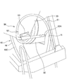
- FIG. 2 is an enlarged perspective view of the rear part of the mixer truck.
- FIG. 3 is a schematic configuration diagram illustrating the drum cleaning device according to the first embodiment.
- FIG. 4A is a schematic configuration diagram illustrating a drum cleaning device according to a second embodiment of the present invention.
- FIG. 4B is a partial longitudinal sectional view of the drum cleaning apparatus according to the second embodiment.
- a mixer truck 1 shown in FIG. 1 is a vehicle that transports ready-mixed concrete put into a mixer drum 10 in a concrete plant.
- the mixer truck 1 is discharged from a mixer drum 10 on which ready-mixed concrete is loaded, a drive device 20 that rotationally drives the mixer drum 10, a hopper 30 that supplies ready-mixed concrete to the mixer drum 10, and the mixer drum 10. And a chute 40 for guiding the ready-mixed concrete to a predetermined position.
- the mixer drum 10 is a cylindrical member whose rear end is formed as an open end 10 ⁇ / b> C (see FIG. 2), and is rotatably mounted on the mount 2 ⁇ / b> A of the vehicle body 2.
- the mixer drum 10 includes an end plate 11 constituting a front closed end, a front shell 12 connected to the rear end of the end plate 11, a center shell 13 connected to the rear end of the front shell 12, and a rear end of the center shell 13. And rear shells 14 connected to each other.
- the rear end of the rear shell 14 constitutes an open end 10 ⁇ / b> C of the mixer drum 10.
- a drive shaft 10 ⁇ / b> A is provided at the front center of the end plate 11 of the mixer drum 10, and a roller ring 10 ⁇ / b> B is provided on the rear outer periphery of the rear shell 14 of the mixer drum 10.
- the drive shaft 10A of the mixer drum 10 is connected to a hydraulic motor (not shown) of the drive device 20 disposed in the front part of the gantry 2A.
- the roller ring 10B of the mixer drum 10 is supported from below by a plurality of rollers 3A of the support portion 3 disposed at the rear portion of the gantry 2A.
- the mixer drum 10 is disposed on the gantry 2 ⁇ / b> A in a forward tilting posture in which the rear part of the drum is lifted upward.
- the mixer drum 10 is configured to rotate forward or backward by a hydraulic motor of the drive device 20.
- a drum blade 15 is spirally disposed along the inner wall surface of the drum. Agitation or the like of the ready-mixed concrete loaded in the mixer drum 10 is performed by the drum blade 15 that rotates together with the mixer drum 10.
- the drum blade 15 moves the ready-mixed concrete in the mixer drum 10 forward while stirring.
- the drum blade 15 moves the ready-mixed concrete backward while stirring.
- the ready-mixed concrete discharged from the mixer drum 10 is guided to a predetermined position via a chute 40 that is pivotably provided at the lower rear portion of the mixer truck 1.
- the mixer drum 10 when throwing ready concrete into the mixer drum 10 via the hopper 30 provided in the rear upper part of the mixer vehicle 1, the mixer drum 10 is rotated forward at a higher speed than during stirring rotation.
- the ready-mixed concrete supplied to the hopper 30 is put into the mixer drum 10 through a seal pipe 32 communicating with the discharge port 31 of the hopper 30.
- the drum cleaning device 50 is a device that cleans the inside of the mixer drum 10 using cleaning water (cleaning liquid).
- the drum cleaning device 50 includes a hose 51 for supplying cleaning water, a cleaning pipe 52 connected to the hose 51, and a holder 53 for fixing the cleaning pipe 52 to the hopper 30. Prepare.
- the hose 51 is, for example, a rubber hose, and is a member that supplies cleaning water to the cleaning pipe 52.
- One end of the hose 51 is connected to a discharge portion of a high-pressure pump (not shown) that pumps cleaning water, and the other end of the hose 51 is connected to a cleaning pipe 52.
- the washing water is stored in a water tank (not shown) arranged in the front part of the gantry 2A, and the high-pressure pump is arranged adjacent to the water tank.
- the cleaning pipe 52 is fixed to the lower part of the outer side surface of the hopper 30 via a holder 53 disposed near the base end.
- the cleaning pipe 52 is fixed to the side of the hopper 30 using the holder 53, but the cleaning pipe 52 may be directly fixed to the hopper 30 without using the holder 53.
- the cleaning pipe 52 is formed as a substantially L-shaped cylindrical member, it may be formed as a linear cylindrical member. Thus, the cleaning pipe 52 is formed in an arbitrary shape as necessary.
- the proximal end of the cleaning pipe 52 is connected to the hose 51.
- the tip of the cleaning pipe 52 is formed as a closed end.
- the tip of the cleaning pipe 52 is inserted into the mixer drum 10 through the open end 10 ⁇ / b> C of the mixer drum 10.
- the cleaning pipe 52 is arranged so that the tip thereof does not interfere with the drum inner wall surface and the drum blade 15.
- a plurality of injection holes 52 ⁇ / b> A that communicate the inside and the outside of the cleaning pipe 52 are formed on the outer peripheral surface of the tip of the cleaning pipe 52. These injection holes 52A are arranged with their positions shifted in the pipe axial direction and with their positions shifted in the pipe circumferential direction.
- the cleaning operation by the drum cleaning device 50 is started.
- the high-pressure pump arranged in parallel with the water tank is driven, and the cleaning water discharged from the high-pressure pump is supplied to the cleaning pipe 52 through the hose 51.
- the cleaning water supplied to the cleaning pipe 52 is sprayed into the mixer drum 10 through the spray holes 52A, and the ready-mixed concrete attached to the drum inner wall surface and the drum blade 15 is washed away.
- the cleaning pipe 52 is configured to move in accordance with an external force applied from the outside. That is, the cleaning pipe 52 is formed of an elastic body such as rubber or plastic so that the pipe itself can be elastically deformed.
- an operator may clean the periphery of the open end 10C of the mixer drum 10 using a brush or the like.
- the cleaning pipe 52 is elastically deformed according to the collision force of the brush, but if the external force such as the collision force of the brush is released, the cleaning pipe 52 is Return to shape.
- the drum cleaning device 50 of the mixer truck 1 according to the first embodiment described above has the following effects.
- the drum cleaning device 50 includes a cleaning pipe 52 having an injection hole 52A for jetting cleaning water, and the cleaning pipe 52 is configured to move according to an external force applied from the outside. That is, the cleaning pipe 52 is formed of an elastic body so that the pipe itself can be elastically deformed.
- the cleaning pipe 52 when an external force is applied to the cleaning pipe 52, the cleaning pipe 52 is elastically deformed according to the external force, and the cleaning pipe 52 does not return to its original shape while being deformed. Accordingly, it is possible to prevent the cleaning pipe 52 from being damaged, and it is possible to suppress a decrease in the cleaning effect due to the cleaning pipe 52 being damaged. In addition, since a brush or the like is not sandwiched between the cleaning pipe 52 and the drum blade 15, not only the cleaning pipe 52 but also the drum blade 15 can be prevented.
- FIGS. 4A and 4B a second embodiment of the present invention will be described with reference to FIGS. 4A and 4B.
- the second embodiment will be described with a focus on differences from the first embodiment.
- FIGS. 4A and 4B the same reference numerals as those in the first embodiment are assigned to the same components as those in the first embodiment.
- the cleaning pipe 52 is a linear cylindrical member and is fixed to the hopper 30 by the holder 60 instead of the holder 53.
- a small diameter portion 52 ⁇ / b> B whose outer diameter is set smaller than the outer diameter of the distal end portion is formed at the proximal end portion of the cleaning pipe 52.
- the small diameter portion 52B is press-fitted into the inner peripheral surface of the end portion of the hose 51, whereby the cleaning pipe 52 and the hose 51 are connected.
- the holder 60 is a member that fixes the cleaning pipe 52 to the hopper 30 (see FIG. 1) so that the cleaning pipe 52 can move according to an external force applied from the outside.
- the holder 60 includes a coil spring 61 that holds the cleaning pipe 52 and a fixing portion 62 that is connected to the coil spring 61 and is fixed to the hopper 30.
- the coil spring 61 is a coil-shaped spring formed by spirally winding a metal or resin wire.
- the coil spring 61 is configured to hold the cleaning pipe 52 from the pipe outer peripheral surface side in a state where the cleaning pipe 52 is inserted in the axial direction. Therefore, the inner diameter of the coil spring 61 and the outer diameter of the cleaning pipe 52 are set to substantially the same diameter.
- the coil spring 61 is disposed around the connection portion between the cleaning pipe 52 and the hose 51, and is attached over both connection ends of the cleaning pipe 52 and the hose 51.
- the fixing portion 62 is formed integrally with the end portion of the coil spring 61 on the hose 51 side, and is fixed to the lower portion of the outer side surface of the hopper 30 via a screw 63. By fixing the fixing portion 62 in this way, the cleaning pipe 52 is disposed such that the tip end portion thereof is inserted into the mixer drum 10 through the opening end 10C.
- the drum cleaning device 50 for the mixer truck 1 according to the second embodiment described above has the following effects.
- the drum cleaning device 50 includes a cleaning pipe 52 having an injection hole 52A for jetting cleaning water, and the cleaning pipe 52 is configured to move according to an external force applied from the outside. That is, the cleaning pipe 52 is configured to be fixed to the hopper 30 via the holder 60 having the coil spring 61 that holds the cleaning pipe 52 in an inserted state, and to be movable by spring deformation of the coil spring 61.
- the cleaning pipe 52 By holding the cleaning pipe 52 by the coil spring 61 of the holder 60 in this way, when an external force is applied to the cleaning pipe 52, the coil spring 61 is bent according to the external force so that the cleaning pipe 52 is movable. When the external force is released, the cleaning pipe 52 returns to the original position by the spring reaction force.
- the cleaning pipe 52 Since the cleaning pipe 52 is moved by the spring deformation of the coil spring 61, the cleaning pipe 52 does not return to its original position while being deformed. Thereby, the effect similar to 1st Embodiment is acquired and it becomes possible to prevent the washing
- the cleaning pipe 52 can be prevented from coming off from the hose 51 when the cleaning pipe 52 is movable, and the cleaning pipe.
- the connection part of 52 and the hose 51 can be protected.
- the cleaning pipe 52 may be formed of a metal as in the conventional case, but may be formed of an elastic body as in the first embodiment.
- the cleaning pipe 52 of the drum cleaning device 50 according to the second embodiment is formed of an elastic body, it is possible to more reliably prevent the cleaning pipe 52 from being damaged.
- the cleaning pipe 52 is fixed to the hopper 30 via the holders 53 and 60, but the fixing position of the cleaning pipe 52 is not limited to this.
- the cleaning pipe 52 may be configured to be fixed to a structure other than the hopper 30 provided in the mixer vehicle 1.
- the inside of the mixer drum 10 is cleaned using cleaning water, but the inside of the mixer drum 10 may be cleaned using a liquid other than water.
Landscapes
- Engineering & Computer Science (AREA)
- Mechanical Engineering (AREA)
- Structural Engineering (AREA)
- Health & Medical Sciences (AREA)
- Public Health (AREA)
- Transportation (AREA)
- Preparation Of Clay, And Manufacture Of Mixtures Containing Clay Or Cement (AREA)
- Cleaning In General (AREA)
- Vehicle Cleaning, Maintenance, Repair, Refitting, And Outriggers (AREA)
Abstract
Description
以下、図1から図3を参照して、本発明の第1実施形態について説明する。
次に、図4A及び図4Bを参照して、本発明の第2実施形態について説明する。第2実施形態については、第1実施形態と相違する部分を中心に説明する。なお、図4A及び図4Bでは、第1実施形態と同一の構成部分には第1実施形態と同一の符号を付している。
Claims (4)
- ミキサ車に搭載されたミキサドラムの内部を洗浄するドラム洗浄装置であって、
洗浄液を供給する洗浄液供給ホースと、
前記洗浄液供給ホースに接続され、先端部が前記ミキサドラムの開口端を通じて当該ミキサドラム内に挿入される洗浄パイプと、
前記洗浄パイプに設けられ、洗浄液を前記ミキサドラム内に噴射する噴射部と、を備え、
前記洗浄パイプは、外部から加えられる外力に応じて可動するように構成される、
ドラム洗浄装置。 - 請求項1に記載のドラム洗浄装置であって、
前記洗浄パイプは、パイプ自体が弾性変形可能なように、弾性体によって形成される、
ドラム洗浄装置。 - 請求項1に記載のドラム洗浄装置であって、
前記ミキサ車に設けられた構造物に前記洗浄パイプを設置するホルダをさらに備え、
前記ホルダは、
前記洗浄パイプを挿通させた状態で、当該洗浄パイプをパイプ外周面側から保持するコイルスプリングと、
前記コイルスプリングに設けられるとともに、前記構造物に固定される固定部と、を備え、
前記洗浄パイプは、前記コイルスプリングのスプリング変形によって可動するように構成される、
ドラム洗浄装置。 - 請求項3に記載のドラム洗浄装置であって、
前記コイルスプリングは、前記洗浄液供給ホースと前記洗浄パイプの接続部分の周囲に配設される、
ドラム洗浄装置。
Priority Applications (5)
| Application Number | Priority Date | Filing Date | Title |
|---|---|---|---|
| US14/421,449 US20150217344A1 (en) | 2013-03-22 | 2014-03-19 | Drum washing apparatus |
| AU2014239344A AU2014239344B2 (en) | 2013-03-22 | 2014-03-19 | Drum washing device |
| DE201411000161 DE112014000161T5 (de) | 2013-03-22 | 2014-03-19 | Trommelreinigungsvorrichtung |
| NZ704694A NZ704694A (en) | 2013-03-22 | 2014-03-19 | Drum washing apparatus |
| CN201480002050.1A CN104520144A (zh) | 2013-03-22 | 2014-03-19 | 筒体清洗装置 |
Applications Claiming Priority (2)
| Application Number | Priority Date | Filing Date | Title |
|---|---|---|---|
| JP2013059802A JP2014184779A (ja) | 2013-03-22 | 2013-03-22 | ドラム洗浄装置 |
| JP2013-059802 | 2013-03-22 |
Publications (1)
| Publication Number | Publication Date |
|---|---|
| WO2014148550A1 true WO2014148550A1 (ja) | 2014-09-25 |
Family
ID=51580224
Family Applications (1)
| Application Number | Title | Priority Date | Filing Date |
|---|---|---|---|
| PCT/JP2014/057534 Ceased WO2014148550A1 (ja) | 2013-03-22 | 2014-03-19 | ドラム洗浄装置 |
Country Status (7)
| Country | Link |
|---|---|
| US (1) | US20150217344A1 (ja) |
| JP (1) | JP2014184779A (ja) |
| CN (1) | CN104520144A (ja) |
| AU (1) | AU2014239344B2 (ja) |
| DE (1) | DE112014000161T5 (ja) |
| NZ (1) | NZ704694A (ja) |
| WO (1) | WO2014148550A1 (ja) |
Cited By (1)
| Publication number | Priority date | Publication date | Assignee | Title |
|---|---|---|---|---|
| CN110981388A (zh) * | 2019-12-06 | 2020-04-10 | 铃鹿复合建材(上海)有限公司 | 一种雕刻砂浆及其喷涂设备 |
Families Citing this family (6)
| Publication number | Priority date | Publication date | Assignee | Title |
|---|---|---|---|---|
| US9802578B2 (en) | 2015-09-11 | 2017-10-31 | Beck Manufacturing International, Inc. | Concrete mixer truck cleaning system |
| US10899318B2 (en) | 2017-02-08 | 2021-01-26 | Con-Tech Manufacturing, Inc. | Onboard wash system |
| KR101937888B1 (ko) * | 2017-10-13 | 2019-04-11 | 전병섭 | 믹서드럼의 세척시스템 |
| CN108556145A (zh) * | 2018-02-06 | 2018-09-21 | 安徽传质信息科技有限公司 | 一种方便清洗的手推式混凝土搅拌器 |
| CN109262846A (zh) * | 2018-10-18 | 2019-01-25 | 南安如盈商贸有限公司 | 一种基于混凝土倾倒时自动清洗的混凝土运输车 |
| CN114714511A (zh) * | 2022-05-11 | 2022-07-08 | 一汽解放汽车有限公司 | 一种搅拌装置和混凝土搅拌车 |
Citations (5)
| Publication number | Priority date | Publication date | Assignee | Title |
|---|---|---|---|---|
| JPH0716549A (ja) * | 1993-06-30 | 1995-01-20 | Mitsui Petrochem Ind Ltd | 洗浄装置 |
| JPH08141455A (ja) * | 1994-11-18 | 1996-06-04 | Tokico Ltd | 塗装ガン洗浄装置 |
| JP2001270378A (ja) * | 2000-03-27 | 2001-10-02 | Aizawa Koatsu Concrete Kk | ミキサ車の洗浄および荷積方法 |
| JP3086924U (ja) * | 2001-12-25 | 2002-07-05 | 優 下田 | 手持噴射清掃用ノズル |
| JP2005199859A (ja) * | 2004-01-15 | 2005-07-28 | Shin Meiwa Ind Co Ltd | ミキサ車 |
Family Cites Families (10)
| Publication number | Priority date | Publication date | Assignee | Title |
|---|---|---|---|---|
| US3088756A (en) * | 1959-08-10 | 1963-05-07 | Aeroquip Corp | Fitting for hose spring guard |
| US5286068A (en) * | 1992-09-10 | 1994-02-15 | Jacob Wiebe | Hose connection |
| US5624074A (en) * | 1995-10-26 | 1997-04-29 | Component Hardware Group, Inc. | Hose sub-assembly |
| US20050235442A1 (en) * | 2004-04-22 | 2005-10-27 | Hammerrock, Inc. | Mechanism for removing concrete accretions from mixing drum |
| JP4467051B2 (ja) * | 2004-05-10 | 2010-05-26 | カヤバ工業株式会社 | 洗浄パイプ構造 |
| US20070086270A1 (en) * | 2005-10-17 | 2007-04-19 | Mcneilus Truck And Manufacturing, Inc. | Concrete mixing drum cleanout apparatus and method |
| US7966724B2 (en) * | 2005-11-09 | 2011-06-28 | Nelson-Dunn, Inc. | Conduit assembly methods |
| WO2009117143A2 (en) * | 2008-03-20 | 2009-09-24 | Hydrochem Industrial Services, Inc. | Automated heat exchanger tube cleaning assembly and system |
| US9249912B2 (en) * | 2010-12-30 | 2016-02-02 | Eaton Corporation | Hose coupling with retaining spring |
| CN202755277U (zh) * | 2012-07-09 | 2013-02-27 | 安徽兴宇重工机械有限责任公司 | 一种整体道床施工系统 |
-
2013
- 2013-03-22 JP JP2013059802A patent/JP2014184779A/ja active Pending
-
2014
- 2014-03-19 NZ NZ704694A patent/NZ704694A/en not_active IP Right Cessation
- 2014-03-19 WO PCT/JP2014/057534 patent/WO2014148550A1/ja not_active Ceased
- 2014-03-19 US US14/421,449 patent/US20150217344A1/en not_active Abandoned
- 2014-03-19 DE DE201411000161 patent/DE112014000161T5/de not_active Withdrawn
- 2014-03-19 AU AU2014239344A patent/AU2014239344B2/en not_active Ceased
- 2014-03-19 CN CN201480002050.1A patent/CN104520144A/zh active Pending
Patent Citations (5)
| Publication number | Priority date | Publication date | Assignee | Title |
|---|---|---|---|---|
| JPH0716549A (ja) * | 1993-06-30 | 1995-01-20 | Mitsui Petrochem Ind Ltd | 洗浄装置 |
| JPH08141455A (ja) * | 1994-11-18 | 1996-06-04 | Tokico Ltd | 塗装ガン洗浄装置 |
| JP2001270378A (ja) * | 2000-03-27 | 2001-10-02 | Aizawa Koatsu Concrete Kk | ミキサ車の洗浄および荷積方法 |
| JP3086924U (ja) * | 2001-12-25 | 2002-07-05 | 優 下田 | 手持噴射清掃用ノズル |
| JP2005199859A (ja) * | 2004-01-15 | 2005-07-28 | Shin Meiwa Ind Co Ltd | ミキサ車 |
Cited By (1)
| Publication number | Priority date | Publication date | Assignee | Title |
|---|---|---|---|---|
| CN110981388A (zh) * | 2019-12-06 | 2020-04-10 | 铃鹿复合建材(上海)有限公司 | 一种雕刻砂浆及其喷涂设备 |
Also Published As
| Publication number | Publication date |
|---|---|
| NZ704694A (en) | 2016-11-25 |
| AU2014239344A1 (en) | 2015-02-26 |
| AU2014239344B2 (en) | 2016-04-14 |
| JP2014184779A (ja) | 2014-10-02 |
| DE112014000161T5 (de) | 2015-04-23 |
| US20150217344A1 (en) | 2015-08-06 |
| CN104520144A (zh) | 2015-04-15 |
Similar Documents
| Publication | Publication Date | Title |
|---|---|---|
| WO2014148550A1 (ja) | ドラム洗浄装置 | |
| JP3187588U (ja) | 配管洗浄ノズル及び配管洗浄装置 | |
| JP4667421B2 (ja) | タンク内洗浄装置 | |
| KR20170063024A (ko) | 파이프 외면 세척장치 | |
| KR101709906B1 (ko) | 회전식 물 배출 세척솔 | |
| US10570556B2 (en) | Spot treating device for a washing machine appliance | |
| JP2012135706A (ja) | 容器内洗浄装置 | |
| CN107227777A (zh) | 杀菌水喷射装置以及配备该杀菌水喷射装置的洁身器 | |
| CN214657505U (zh) | 清洁马桶的系统 | |
| JP6833568B2 (ja) | 清掃装置 | |
| US20130333125A1 (en) | Instrument cleaning assembly and apparatus | |
| JP4710670B2 (ja) | 温水洗浄装置 | |
| JP4393205B2 (ja) | ミキサ車 | |
| US10584474B2 (en) | Septic sensor sprayer | |
| JP3130888U (ja) | 洗浄器 | |
| JP2009279500A (ja) | 配管内清掃ノズル及び配管内清掃装置 | |
| JPH084370Y2 (ja) | 洗浄装置 | |
| JP2019072651A (ja) | ラバーコーン洗浄装置 | |
| JP2005000919A (ja) | 自動洗濯機の回転槽を洗浄する方法、装置及び洗浄作業自動車 | |
| JP4553684B2 (ja) | 洗浄装置 | |
| CN104959330A (zh) | 一种手持式循环布带清洗装置 | |
| JP2007137564A (ja) | 洗浄ホース収納装置 | |
| JP2009165908A (ja) | ロボット洗浄装置 | |
| JP4450415B2 (ja) | ローラ塗装機における塗装補助装置及び塗装補助方法 | |
| CN221792208U (zh) | 一种具有清洗装置的抛光机 |
Legal Events
| Date | Code | Title | Description |
|---|---|---|---|
| 121 | Ep: the epo has been informed by wipo that ep was designated in this application |
Ref document number: 14770313 Country of ref document: EP Kind code of ref document: A1 |
|
| WWE | Wipo information: entry into national phase |
Ref document number: 14421449 Country of ref document: US |
|
| WWE | Wipo information: entry into national phase |
Ref document number: 1120140001619 Country of ref document: DE Ref document number: 112014000161 Country of ref document: DE |
|
| ENP | Entry into the national phase |
Ref document number: 2014239344 Country of ref document: AU Date of ref document: 20140319 Kind code of ref document: A |
|
| 122 | Ep: pct application non-entry in european phase |
Ref document number: 14770313 Country of ref document: EP Kind code of ref document: A1 |