WO2014148268A1 - 射出成形方法 - Google Patents
射出成形方法 Download PDFInfo
- Publication number
- WO2014148268A1 WO2014148268A1 PCT/JP2014/055785 JP2014055785W WO2014148268A1 WO 2014148268 A1 WO2014148268 A1 WO 2014148268A1 JP 2014055785 W JP2014055785 W JP 2014055785W WO 2014148268 A1 WO2014148268 A1 WO 2014148268A1
- Authority
- WO
- WIPO (PCT)
- Prior art keywords
- nozzle
- sprue
- injection molding
- resin
- molding method
- Prior art date
- Legal status (The legal status is an assumption and is not a legal conclusion. Google has not performed a legal analysis and makes no representation as to the accuracy of the status listed.)
- Ceased
Links
Images


Classifications
-
- B—PERFORMING OPERATIONS; TRANSPORTING
- B29—WORKING OF PLASTICS; WORKING OF SUBSTANCES IN A PLASTIC STATE IN GENERAL
- B29C—SHAPING OR JOINING OF PLASTICS; SHAPING OF MATERIAL IN A PLASTIC STATE, NOT OTHERWISE PROVIDED FOR; AFTER-TREATMENT OF THE SHAPED PRODUCTS, e.g. REPAIRING
- B29C45/00—Injection moulding, i.e. forcing the required volume of moulding material through a nozzle into a closed mould; Apparatus therefor
- B29C45/17—Component parts, details or accessories; Auxiliary operations
- B29C45/26—Moulds
- B29C45/27—Sprue channels ; Runner channels or runner nozzles
-
- B—PERFORMING OPERATIONS; TRANSPORTING
- B29—WORKING OF PLASTICS; WORKING OF SUBSTANCES IN A PLASTIC STATE IN GENERAL
- B29K—INDEXING SCHEME ASSOCIATED WITH SUBCLASSES B29B, B29C OR B29D, RELATING TO MOULDING MATERIALS OR TO MATERIALS FOR MOULDS, REINFORCEMENTS, FILLERS OR PREFORMED PARTS, e.g. INSERTS
- B29K2995/00—Properties of moulding materials, reinforcements, fillers, preformed parts or moulds
- B29K2995/0012—Properties of moulding materials, reinforcements, fillers, preformed parts or moulds having particular thermal properties
- B29K2995/0013—Conductive
Definitions
- the present invention relates to an injection molding method, for example, an injection molding method used for manufacturing a resin optical component (plastic lens or the like).
- a sprue bush for injecting molten resin into a mold is usually used.
- the sprue bush is provided on the fixed mold, and has a nozzle touch portion on the surface to which the nozzle of the injection molding machine is in close contact, and is used for injecting the resin injected from the contacted nozzle into the mold. It has a channel inside.
- Patent Document 1 proposes a sprue bush made of a low heat conductive material
- Patent Documents 2 to 6 propose sprue bushes having a nozzle touch portion made of a heat insulating material.
- ZiRKON trade name
- Patent Document 7 proposes a sprue bushing in which a heat insulating layer is provided in the flow path in order to reduce the pressure loss of the resin passing through the flow path.
- E. S. Sprue bushing (trade name) is also known.
- Resin stringing refers to a phenomenon in which molten resin in a nozzle adheres to the tip of a sprue of a molded product, and the resin expands into a fibrous shape when the movable mold is opened.
- this threading occurs, the threading part is sandwiched between the nozzle and the sprue bushing or between the sprue bushing and the mold when the next molding cycle is started, and good injection molding becomes impossible. .
- the present invention has been made in view of such problems, and an object thereof is to provide an injection molding method in which resin stringing does not occur when a sprue is released.
- the injection molding method of the first invention uses a sprue bush composed entirely of a low thermal conductivity material having a thermal conductivity of 20 W / m ⁇ K or less as a mold for injection molding.
- the resin is injected by bringing the nozzle into contact with the sprue bush, and the sprue is released while the nozzle is in contact with the sprue bush.
- the injection molding method of the second invention is characterized in that, in the first invention, the difference between the nozzle temperature and the mold temperature is within 200 ° C.
- the low thermal conductive material constituting the nozzle touch portion comprising the portion in contact with the nozzle and the vicinity thereof in the sprue bush is a metal material.
- the injection molding method according to a fourth aspect of the present invention is characterized in that, in any one of the first to third aspects of the invention, the entire sprue bush is made of an integral metal material.
- the injection molding method of the fifth invention is characterized in that, in the third or fourth invention, the metal material is a titanium alloy.
- the injection molding method of the sixth invention is characterized in that, in the third or fourth invention, the metal material is a heat-resistant and corrosion-resistant alloy.
- a seventh aspect of the present invention there is provided the injection molding method according to any one of the first to sixth aspects, wherein a hard film is applied to at least the surface of the sprue bushing that contacts the nozzle. .
- the injection molding method according to an eighth aspect of the present invention is the method according to any one of the first to seventh aspects, wherein the thermal conductivity of the low thermal conductivity material is 13 W / m ⁇ K or less, and the nozzle temperature and the mold temperature are The difference is within 180 ° C.
- the injection molding method according to a ninth aspect of the present invention is the method according to the third aspect, wherein the thermal conductivity of the metal material constituting the nozzle touch portion comprising the portion in contact with the nozzle and the vicinity thereof in the sprue bush is 13 W / m ⁇ K or less.
- the difference between the nozzle temperature and the mold temperature is within 180 ° C.
- a method for manufacturing an injection molded product according to a tenth aspect of the invention is characterized in that a resin is molded by the injection molding method according to any one of the first to ninth aspects of the invention.
- the sprue bush composed entirely of a low thermal conductivity material having a thermal conductivity of 20 W / m ⁇ K or less is used for the mold for injection molding.
- the heat conduction between the low temperature sprue bush and the high temperature nozzle can be reduced. Therefore, the nozzle tip portion of the injection molding machine can be prevented from being excessively cooled by the sprue bushing, and the resin stored at the nozzle tip can be maintained at an appropriate viscosity in a semi-molten state.
- the sprue is released while the nozzle is in contact with the sprue bushing (that is, in the nozzle touch state), only the portion of the sprue bush that contacts the nozzle and the nozzle touch portion in the vicinity thereof are kept at a relatively high temperature. Be drunk. As a result, the formed sprue tip can be released while being kept at a relatively high temperature, so that only the tip can be taken out in a softened state.
- the combination of the fact that the sprue bushing is made of a low heat conductive material and the sprue being released from the sprue bush in a nozzle touch state makes it possible to cut the resin when the sprue is released, and to soften the sprue tip. Therefore, the stringing phenomenon in which the molten resin is fused and stretched does not occur. Therefore, according to the injection molding method of the present invention, it is possible to prevent resin stringing when the sprue is released.
- the softened portion and the semi-molten portion can be easily formed, and the reliability of the stringing prevention effect is improved.
- the nozzle touch portion made of a metal material in the sprue bush and the portion in contact with the nozzle and its vicinity is elastically deformed by contact with the nozzle. Therefore, it is possible to prevent the nozzle touch portion from being damaged by the impact force of the nozzle touch.
- the entire sprue bushing is integrally formed of a metal material, the sprue bushing is easy to manufacture and has the effect of preventing damage due to the impact force of the nozzle touch. can get.
- the metal material is a titanium alloy
- high-precision injection molding using a sprue bush having an excellent balance between thermal conductivity and workability can be performed.
- the metal material is a heat-resistant and corrosion-resistant alloy
- high-precision injection molding using a sprue bush excellent in thermal conductivity and heat and corrosion resistance can be performed.
- the scratch resistance, wear resistance, and corrosion resistance of the portion in contact with the nozzle are improved by the hard film regardless of the physical properties of the low thermal conductive material, so that the precision deterioration due to resin leakage is deteriorated. This can prevent and improve the life of the sprue bushing.
- the reliability of the stringing prevention effect is further improved by setting a more preferable thermal conductivity and a more preferable temperature difference between the nozzle and the mold.
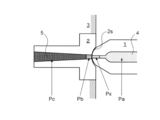
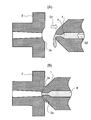
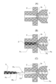
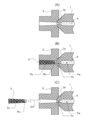
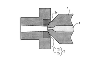
- Sectional drawing which shows the resin state in the nozzle and sprue bush used for one Embodiment of injection molding. Sectional drawing for demonstrating a problem in case a nozzle and a sprue bush repeat a contact and non-contact for every cycle. Sectional drawing which shows the injection molding operation
- stringing of the resin 4 may occur when the sprue is released.
- the stringing part (the stringing part Ps in FIG. 3) shifts to the next molding cycle, it is between the fixed mold and the movable mold (not shown). So that stable molding becomes more difficult.
- FIG. 3A shows a state in which the nozzle 1 is brought into contact with the sprue bush 2 made of a highly heat conductive material.
- FIG. 3B shows a state in which the resin 4 is injected from the nozzle 1 into the sprue bush 2.
- the resin 4 injected into the sprue bush 2 is in a solidified state with the heat of the entire sprue 5 being taken away by the sprue bush 2.
- the temperature of the resin 4 in the tip of the nozzle 1 is greatly lowered and becomes softened. Therefore, the resin 4 is roughly divided into three states. That is, the melted portion Pa made of the molten resin 4 and the softened portion Pb made of the softened resin 4 are present in the nozzle 1, and the solidified portion Pc made of the solidified resin 4 serves as the sprue 5. 2 will exist. Since the softened portion Pb and the solidified portion Pc are integrally cooled, there is no clear boundary between them, and the coupling is strong.
- FIG. 3C shows a state where the sprue 5 is released from the sprue bush 2.
- the tip of the sprue 5 is separated from the tip of the nozzle 1 by release (arrow Q3)
- the softened part Pb in the nozzle 1 is integrated with the solidified part Pc and comes out of the nozzle 1.
- the resin 4 in the melted portion Pa stored in the nozzle 1 is not solidified, the resin 4 adheres to the softened portion Pb and expands with release. That is, stringing of the resin 4 occurs.
- the generated yarn drawing portion Ps becomes a cause of hindering stable molding.
- FIG. 4A shows a state in which the nozzle 1 is brought into contact with the sprue bush 2 made of a low heat conductive material.
- the temperature of the sprue bush 2 is unlikely to decrease. Further, if at least the nozzle touch portion 2 s is made of a metal material in the sprue bush 2, the nozzle touch portion 2 s is elastically deformed by contact with the nozzle 1, so that the nozzle touch portion 2 s is prevented from being damaged by the impact of the nozzle touch. It is also possible.
- FIG. 4B shows a state in which the resin 4 is injected from the nozzle 1 into the sprue bush 2.
- the resin 4 injected into the sprue bush 2 is deprived of heat by the sprue bush 2 at a portion other than the tip of the sprue 5 and becomes solidified. Since the sprue bush 2 is at a high temperature near the tip of the sprue 5, the resin 4 is not easily deprived of heat by the sprue bush 2 and is maintained in a softened state. That is, the softened state of the resin 4 is obtained in the sprue bush 2.
- the resin 4 exists roughly as four states. That is, the melted portion Pa made of the molten resin 4 and the semi-melted portion Px made of the semi-molten resin 4 are present in the nozzle 1, and the softened portion Pb made of the softened resin 4 and the solidified state The solidified portion Pc made of the resin 4 is present in the sprue bush 2 as the sprue 5. Since the softened portion Pb and the solidified portion Pc are integrally cooled, there is no clear boundary between them, and the coupling is strong.
- FIG. 4C shows a state where the sprue 5 is released from the sprue bush 2.
- FIG. 5 shows the state of the resin 4 in the nozzle 1 after the sprue 5 is released from the sprue bush 2.
- the sprue bush 2 is made of a highly heat-conductive material, as shown in FIG. 5 (A)
- the molten resin 4 moves forward toward the tip space of the nozzle 1 generated by the release of the sprue 5 due to the back pressure Q2.
- it moves to, it will be in a softened state as mentioned above, and movement of resin will stop.
- the fluidity of the softened part Pb is significantly lower than that of the melted part Pa. For this reason, an excessive pressure is required at the time of injection in the next cycle, and injection stability is impaired.
- a semi-molten portion Px exists at the tip of the nozzle 1 as shown in FIG. That is, as shown in FIG. 4C, since the sprue 5 is released while maintaining the nozzle touch state, the state in which the tip of the nozzle 1 is appropriately deprived of heat by the sprue bush 2 is maintained. The semi-molten state of the resin 4 in the tip is maintained.
- the semi-molten portion Px in the tip of the nozzle 1 has a moderately high viscosity and can withstand back pressure, and functions as a plug that closes the tip of the nozzle 1.
- the semi-molten part Px Since the semi-molten part Px has low strength, the semi-molten part Px can be easily broken by the injection pressure of the next cycle, and the flow of the resin 4 is not hindered. Further, the entire sprue bushing 2 is made of a low heat conductive material, and therefore, the temperature of the nozzle touch portion 2s is not easily raised and lowered (high temperature insulation in the region Tb in FIG. 5B). The heat of the resin 4 is less likely to be taken away by the sprue bush 2. Therefore, the fluidity of the resin 4 is hardly deteriorated, the filling pressure can be reduced, and the injection pressure is stabilized.
- the semi-molten portion Px has a function of preventing the occurrence of stringing, and also has a function of a stopper that appropriately prevents the resin 4 from leaking. Then, stable precision molding can be performed by the plug function of the semi-molten portion Px and the filling pressure reduction and injection stabilization due to the sprue bushing 2 made of a low heat conductive material. This stabilization of precision molding is particularly important in the injection molding of resin optical parts (plastic lenses and the like).
- thermoplastic resin 4 used is an olefin resin
- sample 1 is Ti-6Al-4V (JIS 60 types)
- sample 2 is Incoloy 800 (trade name, manufactured by Special Metals)
- sample 3 is STAVAX (trade name, Woodeholm).
- Sample 4 is K340 (trade name, manufactured by Woodeholm)
- sample 5 is YAG (trade name, manufactured by Hitachi Metals)
- sample 6 is DC53 (trade name, manufactured by Daido Special Steel Co., Ltd.). is there.
- the thermal conductivity of the low thermal conductivity material constituting the sprue bushing 2 is preferably 20 W / m ⁇ K or less, and more preferably 13 W / m ⁇ K or less. Therefore, the injection molding method shown in FIG. 4 is an embodiment using the sprue bush 2 made of a low thermal conductivity material, and the feature is that the thermal conductivity is 20 W / m ⁇ K or less (preferably 13 W / m ⁇ ).
- the sprue bush 2 entirely composed of a low heat conductive material (K or less) is used for an injection mold 3 as shown in FIG. 1, for example, and the nozzle 1 is brought into contact with the sprue bush 2 to inject the resin 4.
- the temperature is relatively low.
- the heat conduction between the sprue bush 2 and the high-temperature nozzle 1 can be reduced. Therefore, it is possible to prevent the tip portion of the nozzle 1 of the injection molding machine from being excessively cooled by the sprue bush 2 and to maintain the resin 4 stored at the tip of the nozzle 1 at an appropriate viscosity in a semi-molten state. Can do.
- the release of the sprue 5 is performed while the nozzle 1 is in contact with the sprue bush 2 (that is, in a nozzle touch state), only the portion of the sprue bush 2 in contact with the nozzle 1 and the nozzle touch portion 2s formed in the vicinity thereof are included. It is kept at a relatively high temperature. As a result, the tip of the sprue 5 to be formed can be released while being kept at a relatively high temperature, so that only the tip of the sprue 5 can be taken out in a softened state.
- the combination of the fact that the sprue bush 2 is made of a low heat conductive material and the release of the sprue 5 in a nozzle touch state from the sprue bush 2 cuts the resin 4 when the sprue 5 is released.
- the stringing phenomenon in which the resin 4 in the melted portion Pa is fused and stretched does not occur. Therefore, according to this injection molding method, the stringing of the resin 4 when the sprue 5 is released can be prevented.
- the resin 4 stored in the nozzle 1 is in a semi-molten state having a high viscosity, and the injection is not hindered while preventing the resin 4 in the nozzle 1 from leaking out.
- the heat flow in the sprue bush 2 is low, so that the fluidity during injection is good.
- the difference between the nozzle temperature and the mold temperature is preferably within 200 ° C, more preferably within 180 ° C.
- the internal temperature of the mold 3 is preferably 100 ° C or higher, more preferably 120 ° C or higher. If set in this way, the resin 4 does not harden too much at the tip of the sprue bushing 2. Therefore, the softened portion Pb and the semi-molten portion Px can be easily formed, and the reliability of the stringing prevention effect is improved.
- the thermal conductivity of the low thermal conductivity material is 13 W / m ⁇ K or less, and the difference between the nozzle temperature and the mold temperature is within 180 ° C.
- the low heat conductive material constituting the nozzle touch portion 2s formed of the portion in contact with the nozzle 1 and the vicinity thereof in the sprue bush 2 is a metal material. If comprised in that way, since the nozzle touch part 2s comprised with the metal material will elastically deform by the contact with the nozzle 1, it can prevent that the nozzle touch part 2s is damaged by the impact force of a nozzle touch.
- the range of the nozzle touch portion 2 s is twice or more the flow path entrance area of the sprue 5, and the thickness is 5% to 50% of the flow path length of the sprue 5.
- the sprue bush 2 may be constituted by a sprue bush main body 2a and a nozzle touch part 2b, and the nozzle touch part 2b made of a metal material may be fitted into the sprue bush main body 2a to constitute a nested structure.
- Both the sprue bushing main body 2a and the nozzle touch part 2b may be made of a low heat conductive material.
- the sprue bushing main body 2a may be made of a ceramic heat insulating material, and only the nozzle touch part 2b may be made of a metal material. Good. Since the nozzle touch component 2b made of a metal material is elastically deformed by contact with the nozzle 1, the nozzle touch component 2b can be prevented from being damaged by the impact force of the nozzle touch. In addition, the formation of the solidified portion Pc and the softened portion Pb can be easily controlled.
- the thermal conductivity on the nozzle touch component 2b side In consideration of productivity, it is preferable to reduce the thermal conductivity on the nozzle touch component 2b side.
- the sprue bushing body 2a In order to respond to the desire to promote cooling with a certain degree of high thermal conductivity, for example, the sprue bushing body 2a has a thermal conductivity close to a relatively high thermal conductivity: 16 to 20 W / m ⁇ K, and only the nozzle touch portion is thermally conductive. By making the balance at a rate of 16 W / m ⁇ K or less, it is possible to increase productivity while maintaining the above-described anti-stringing effect.
- the thermal conductivity of the metal material constituting the nozzle touch portion 2s composed of the portion in contact with the nozzle 1 and the vicinity thereof. Is more preferably 13 W / m ⁇ K or less, and the difference between the nozzle temperature and the mold temperature is preferably within 180 ° C.
- the entire sprue bushing 2 may be made of an integral metal material. If the entire sprue bushing 2 is integrally formed of a metal material, the sprue bushing 2 can be easily manufactured, and the effect of preventing damage due to the impact force of the nozzle touch can be obtained.
- the metal material is preferably a titanium alloy. If a titanium alloy is used as the metal material, high-precision injection molding using the sprue bushing 2 having an excellent balance between thermal conductivity and workability can be performed. Examples of the titanium alloy include Ti-6Al-4V, Ti-15V-3Cr-3Al-3Sn, Ti-5Al-2.5Sn, and the like.
- the metal material is preferably a heat and corrosion resistant alloy. If a heat-resistant and corrosion-resistant alloy is used as the metal material, high-precision injection molding using the sprue bushing 2 excellent in thermal conductivity and heat and corrosion resistance can be performed. Examples of the heat-resistant and corrosion-resistant alloy include Hastelloy C276 manufactured by Haynes, Incoloy 800 manufactured by Special Metals, and the like.
- a hard coating 2 c it is preferable to apply a hard coating 2 c to at least the surface of the sprue bush 2 that contacts the nozzle 1. If the sprue bush 2 is provided with a hard coating 2c, the hard coating 2c improves the scratch resistance, wear resistance, and corrosion resistance of the portion that contacts the nozzle 1 (for example, the nozzle touch portion 2s) regardless of the physical properties of the low thermal conductivity material. Therefore, it is possible to prevent deterioration of precision due to resin leakage and improve the life of the sprue bush 2.
- Examples of the hard coating 2c include TiN coating (thickness: 3 ⁇ m) and DLC coating (thickness: 0.5 ⁇ m).
- the hardness is ensured by providing the hard coating 2c, and the precision of precision molding is improved. Can do. Further, by providing a corrosion-resistant and wear-resistant TiN film, a long-life sprue bushing can be obtained without being affected by the characteristics of the base material of the sprue bushing 2.
Landscapes
- Engineering & Computer Science (AREA)
- Manufacturing & Machinery (AREA)
- Mechanical Engineering (AREA)
- Injection Moulding Of Plastics Or The Like (AREA)
- Moulds For Moulding Plastics Or The Like (AREA)
Abstract
熱伝導率が20W/m・K以下の低熱伝導材料で全体が構成されたスプルーブッシュを射出成形用の金型に用いる射出成形方法である。スプルーブッシュにノズルを接触させて樹脂の注入を行い、スプルーブッシュにノズルを接触させたままスプルーの離型を行う。
Description
本発明は射出成形方法に関するものであり、例えば、樹脂製光学部品(プラスチックレンズ等)の製造に使用する射出成形方法に関するものである。
射出成形を行う場合、溶融状態の樹脂を金型内に注入するためのスプルーブッシュが通常用いられる。スプルーブッシュは固定側金型に設けられ、射出成形機のノズルが密着されるノズルタッチ部分を表面に有しており、その密着状態のノズルから射出された樹脂を金型内に注入するための流路を内部に有している。
スプルーブッシュとしては、ノズルとの接触を考慮した様々なタイプのものが提案されている。例えば、特許文献1には低熱伝導材料からなるスプルーブッシュが提案されており、特許文献2~6にはノズルタッチ部分が断熱材からなるスプルーブッシュが提案されている。ノズルタッチ部分が断熱材からなる製品として、スパイラルロジック社製ZiRKON(商品名)も知られている。また特許文献7には、流路を通過する樹脂の圧力損失を軽減するために、流路に断熱層が設けられたスプルーブッシュが提案されており、それと同様に構成された製品として、ロイアルエンジニアリング社製E.S.スプルーブッシュ(商品名)も知られている。
しかし、従来より知られているスプルーブッシュを用いて射出成形を行うと、スプルーを離型したときに樹脂の糸引きが生じる場合がある。樹脂の糸引きとは、成形品のスプルーの先端にノズル内の溶融樹脂が癒着し、可動側金型が開いたときに樹脂が繊維状に伸びて取り出される現象をいう。この糸引きが発生すると、次の成形サイクルに移行した時に糸引き部分がノズルとスプルーブッシュとの間やスプルーブッシュと金型との間に挟み込まれてしまい、良好な射出成形が不可能になる。
本発明はこのような問題点に鑑みてなされたものであって、その目的は、スプルーを離型したときに樹脂の糸引きが生じない射出成形方法を提供することにある。
上記目的を達成するために、第1の発明の射出成形方法は、熱伝導率が20W/m・K以下の低熱伝導材料で全体が構成されたスプルーブッシュを射出成形用の金型に用い、スプルーブッシュにノズルを接触させて樹脂の注入を行い、スプルーブッシュにノズルを接触させたままスプルーの離型を行うことを特徴とする。
第2の発明の射出成形方法は、上記第1の発明において、ノズル温度と金型温度との差が200℃以内であることを特徴とする。
第3の発明の射出成形方法は、上記第1又は第2の発明において、前記スプルーブッシュにおいてノズルと接触する部分及びその近傍からなるノズルタッチ部分を構成する低熱伝導材料が金属材料であることを特徴とする。
第4の発明の射出成形方法は、上記第1~第3のいずれか1つの発明において、前記スプルーブッシュの全体が一体の金属材料で構成されていることを特徴とする。
第5の発明の射出成形方法は、上記第3又は第4の発明において、前記金属材料がチタン合金であることを特徴とする。
第6の発明の射出成形方法は、上記第3又は第4の発明において、前記金属材料が耐熱耐食合金であることを特徴とする。
第7の発明の射出成形方法は、上記第1~第6のいずれか1つの発明において、前記スプルーブッシュにおいて少なくともノズルと接触する部分の表面に、硬質皮膜が付与されていることを特徴とする。
第8の発明の射出成形方法は、上記第1~第7のいずれか1つの発明において、前記低熱伝導材料の熱伝導率が13W/m・K以下であり、ノズル温度と金型温度との差が180℃以内であることを特徴とする。
第9の発明の射出成形方法は、上記第3の発明において、前記スプルーブッシュにおいてノズルと接触する部分及びその近傍からなるノズルタッチ部分を構成する金属材料の熱伝導率が13W/m・K以下であり、ノズル温度と金型温度との差が180℃以内であることを特徴とする。
第10の発明の射出成形品の製造方法は、上記第1~第9のいずれか1つの発明に係る射出成形方法で樹脂の成形を行うことを特徴とする。
第1の発明に係る射出成形方法では、熱伝導率が20W/m・K以下の低熱伝導材料で全体が構成されたスプルーブッシュを射出成形用の金型に用いる構成になっているので、相対的に低温のスプルーブッシュと高温のノズルとの間の熱伝導を低減することができる。したがって、射出成形機のノズル先端部分がスプルーブッシュにより過度に冷却されるのを防ぐことができ、ノズル先端に貯留された樹脂を半溶融状態の適切な粘度に維持することができる。また、スプルーブッシュにノズルを接触させたまま(つまりノズルタッチ状態で)スプルーの離型を行うので、スプルーブッシュにおいてノズルと接触する部分及びその近傍からなるノズルタッチ部分のみが比較的高温状態に保たれる。その結果、形成されるスプルー先端部は比較的高温状態に保たれたまま離型可能となるので、スプルーをその先端部のみ軟化状態で取り出すことができる。
上記のように、スプルーブッシュが低熱伝導材料からなることと、スプルーがスプルーブッシュからノズルタッチ状態で離型されることと、の組み合わせにより、スプルー離型時の樹脂の切断が、スプルー先端の軟化部とノズル先端の半溶融部との境界で良好に行われるため、溶融樹脂が癒着して伸長する糸引き現象は発生しない。したがって、本発明の射出成形方法によれば、スプルーを離型したときの樹脂の糸引きを防止することができる。
第2の発明に係る射出成形方法によると、スプルーブッシュの先端で樹脂が固まりすぎないため、軟化部と半溶融部の形成が容易になり、糸引き防止効果の確実性が向上する。
第3の発明に係る射出成形方法では、スプルーブッシュにおいてノズルと接触する部分及びその近傍からなるノズルタッチ部分が金属材料で構成されているため、ノズルタッチ部分はノズルとの接触により弾性変形する。したがって、ノズルタッチ部分がノズルタッチの衝撃力によって破損するのを防ぐことができる。
第4の発明に係る射出成形方法では、スプルーブッシュの全体が金属材料で一体的に構成されているため、スプルーブッシュの製作は容易であり、ノズルタッチの衝撃力による破損を防止するという効果も得られる。
第5の発明に係る射出成形方法では、金属材料がチタン合金であるため、熱伝導率と加工性とのバランスに優れたスプルーブッシュを用いた高精度の射出成形を行うことができる。また、第6の発明に係る射出成形方法では、金属材料が耐熱耐食合金であるため、熱伝導率と耐熱・耐食性とに優れたスプルーブッシュを用いた高精度の射出成形を行うことができる。
第7の発明に係る射出成形方法によると、低熱伝導材料の物性を問わず、ノズルと接触する部分の耐傷性,耐摩耗性,耐食性が硬質皮膜によって向上するため、樹脂漏れによる精密性悪化を防ぐと共にスプルーブッシュの寿命を向上させることができる。
第8又は第9の発明に係る射出成形方法では、更に好ましい熱伝導率の設定、ノズルと金型との更に好ましい温度差の設定により、糸引き防止効果の確実性が更に向上する。
第10の発明に係る射出成形品の製造方法では、上述した射出成形方法で樹脂の成形を行う構成になっているため、スプルーを離型したときの樹脂の糸引きを防止して、高精度の射出成形品を安定的に製造することが可能となる。
以下、本発明を実施した射出成形方法等を、図面を参照しつつ説明する。射出成形装置の全体図は省略するが、溶融樹脂は固定側金型のスプルーブッシュを通って、金型内部の空間に射出され、金型内で冷却された後に可動側金型を開いて成形品として取り出される構成になっている。なお、実施の形態,参考・比較のための形態等の相互で同一の部分や相当する部分には同一の符号を付して重複説明を適宜省略する。
ノズルとスプルーブッシュとが1サイクル毎に接触と非接触を繰り返す射出成形においては、例えば、図2(A)に示すようにノズル1が後退して(矢印Q1)スプルーブッシュ2から離れると、大気圧より高い圧力(背圧Q2)でノズル1内に溜められた溶融状態の樹脂4が、ノズル1の先端から漏れることがある。これは、ノズル1の先端がスプルーブッシュ2から離れることによって温度上昇し、先端内部の樹脂4が軟化状態や半溶融状態から溶融状態へ変化するためである。
図2(A)に示す状態のまま次の成形サイクルに移行してノズルタッチを行うと、図2(B)に示すようにノズル1とスプルーブッシュ2との間に樹脂4が不均一に挟まれてしまい、その結果、空間2kが生じることになる。空間2kが生じるとノズル1とスプルーブッシュ2との密着が損なわれるため、空間2kから樹脂漏れが生じたり樹脂4の圧力損失が増大したりして安定成形が困難になる。さらに、ノズル1からスプルーブッシュ2への伝熱が悪くなるため、スプルーブッシュ2においてノズル1と接触する部分及びその近傍からなるノズルタッチ部分2sを、効率的に加熱することができなくなってしまう。
ノズルタッチ部分2sを効率的に加熱することができないと、スプルーを離型したときに樹脂4の糸引きが生じる場合がある。樹脂4の糸引きが発生すると、その糸引き部分(図3中の糸引き部Ps)が、次の成形サイクルに移行した時に、固定側金型と可動側金型(不図示)との間に挟み込まれてしまい、安定成形が更に困難になる。
ノズル1とスプルーブッシュ2との密着状態を保ったとしても、スプルーブッシュ2を高熱伝導材料で構成した場合、上記と同様、ノズルタッチ部分2sを効率的に加熱することが困難になる。図3(A)に、高熱伝導材料からなるスプルーブッシュ2にノズル1を接触させた状態を示す。このようにノズルタッチを行うと、固定側金型により冷却されているスプルーブッシュ2のノズルタッチ部分2sは加熱されるが、スプルーブッシュ2の全体が高熱伝導材料で構成されているため、スプルーブッシュ2の温度は下がり易い。
図3(B)に、スプルーブッシュ2にノズル1から樹脂4の注入を行った状態を示す。スプルーブッシュ2に注入された樹脂4は、スプルー5の全体で熱をスプルーブッシュ2に奪われて、固化状態となる。また、ノズル1の先端部もスプルーブッシュ2に熱を奪われるので、ノズル1の先端内の樹脂4の温度も大きく低下して軟化状態となる。したがって、樹脂4は大きく分けて3つの状態として存在することになる。つまり、溶融状態の樹脂4からなる溶融部Paと、軟化状態の樹脂4からなる軟化部Pbと、がノズル1内に存在し、固化状態の樹脂4からなる固化部Pcがスプルー5としてスプルーブッシュ2内に存在することになる。軟化部Pbと固化部Pcは、一体で冷却が進んだものであるから、両者の間に明確な境界はなく、結合は強い。
図3(C)に、スプルーブッシュ2からスプルー5を離型した状態を示す。スプルー5の先端が離型(矢印Q3)によってノズル1の先端から分離される際、ノズル1内の軟化部Pbが固化部Pcと一体になってノズル1内から抜け出る。この時、ノズル1内に貯留された溶融部Paの樹脂4は、固化していないため軟化部Pbに癒着して、離型に伴って伸長する。つまり、樹脂4の糸引きが発生することになる。発生した糸引き部Psは、前述したように、安定成形を阻害する原因となる。
糸引きの発生を効果的に防止するには、ノズル1とスプルーブッシュ2との密着状態を保つだけでなく、スプルーブッシュ2を低熱伝導材料で構成することによって、ノズルタッチ部分2sを効率的に加熱することが好ましい。図4(A)に、低熱伝導材料からなるスプルーブッシュ2にノズル1を接触させた状態を示す。このようにノズルタッチを行うと、固定側金型により冷却されているスプルーブッシュ2においてノズル1と接触する部分及びその近傍からなるノズルタッチ部分2sは加熱されるが、スプルーブッシュ2の全体が低熱伝導材料で構成されているため、スプルーブッシュ2の温度は下がりにくい。また、スプルーブッシュ2において少なくともノズルタッチ部分2sを金属材料で構成すれば、ノズルタッチ部分2sがノズル1との接触により弾性変形するため、ノズルタッチ部分2sがノズルタッチの衝撃によって破損することを防ぐことも可能となる。
図4(B)に、スプルーブッシュ2にノズル1から樹脂4の注入を行った状態を示す。スプルーブッシュ2に注入された樹脂4は、スプルー5の先端を除く部分で熱をスプルーブッシュ2に奪われて、固化状態となる。スプルー5の先端付近では、スプルーブッシュ2が高温になっているので、樹脂4はスプルーブッシュ2で熱を奪われにくく、軟化状態で維持される。つまり、スプルーブッシュ2内で樹脂4の軟化状態が得られる。
また、ノズル1の先端部もスプルーブッシュ2に熱を奪われにくいので、ノズル1の先端内の樹脂4の温度が少し低下して半溶融状態となる。したがって、樹脂4は大きく分けて4つの状態として存在することになる。つまり、溶融状態の樹脂4からなる溶融部Paと、半溶融状態の樹脂4からなる半溶融部Pxと、がノズル1内に存在し、軟化状態の樹脂4からなる軟化部Pbと、固化状態の樹脂4からなる固化部Pcと、がスプルー5としてスプルーブッシュ2内に存在することになる。軟化部Pbと固化部Pcは、一体で冷却が進んだものであるから、両者の間に明確な境界はなく、結合は強い。
図4(C)に、スプルーブッシュ2からスプルー5を離型した状態を示す。スプルー5の先端が離型(矢印Q3)によってノズル1の先端から分離される際、ノズル1内の半溶融部Pxは強度が低く、容易に破壊されるため、軟化部Pbと半溶融部Pxとは両者の境界で良好に分断され、軟化部Pbと固化部Pcが一体になってノズル1内から抜け出る。したがって、樹脂4の糸引きは発生しない。
図5に,スプルーブッシュ2からスプルー5が離型した後の、ノズル1内の樹脂4の状態を示す。スプルーブッシュ2が高熱伝導材料からなる場合、図5(A)に示すように、溶融状態の樹脂4が背圧Q2により、スプルー5の離型によって生じた、ノズル1の先端空間に向かって前方へ移動すると、前述したように軟化状態となり、樹脂の移動は止まる。軟化部Pbは、溶融部Paに比べて流動性が著しく低下している。このため、次のサイクルの射出時に過大な圧力が必要となり、射出安定性が損なわれることになる。さらには、高圧を加えても射出できない「ノズル詰まり」現象が発生するおそれもある。従来より知られている射出成形では、糸引きを解消するために、スプルーブッシュ2のノズルタッチ部分2sの温度が上がらないように冷却することが重視されてきたが、ノズルタッチ部分2sの温度を低くすると(図5(A)中の領域Taの低温化)、上記射出不安定化やノズル詰まりを招いてしまう。
スプルーブッシュ2が低熱伝導材料からなる場合、図5(B)に示すように、ノズル1の先端には半溶融部Pxが存在する。つまり、図4(C)に示すように、ノズルタッチ状態を維持したままスプルー5が離型するので、ノズル1の先端がスプルーブッシュ2に適度に熱を奪われる状態が維持され、ノズル1の先端内の樹脂4の半溶融状態が維持される。ノズル1の先端内の半溶融部Pxは、適度に粘度が高いので背圧に耐えることができ、ノズル1の先端を塞ぐ栓として機能する。半溶融部Pxは強度が低いため、次サイクルの射出圧力で半溶融部Pxを簡単に破壊することができ、樹脂4の流動が妨げられることはない。また、スプルーブッシュ2全体が低熱伝導材料からなっていることと、それゆえにノズルタッチ部分2sの温度が高くなり下がりにくくなり(図5(B)中の領域Tbの高温保温化)、射出中の樹脂4の熱がスプルーブッシュ2に奪われにくくなる。したがって、樹脂4の流動性が悪化しにくく、充填圧力を低減することができ、射出圧力が安定する。
半溶融部Pxは、上記のように、糸引きの発生を防止する機能を有するとともに、樹脂4の漏出を適正に防ぐ栓としての機能を持っている。そして、半溶融部Pxの栓機能と、スプルーブッシュ2が低熱伝導材料からなることによる充填圧力低減及び射出安定化と、によって、安定した精密成形を行うことが可能となる。この精密成形の安定化は、樹脂製光学部品(プラスチックレンズ等)の射出成形において特に重要である。
次に、スプルーブッシュ2を構成する材料の熱伝導率,ノズル1と金型3との温度差等について説明する。表1に、熱伝導率がそれぞれ異なる材料からなるスプルーブッシュ2をサンプル1~6として、ノズル1と金型3との温度差を変えてスプルー5の離型を行ったときの「糸引き」に関する評価結果を示す。使用した熱可塑性の樹脂4はオレフィン樹脂であり、サンプル1はTi-6Al-4V(JIS60種)、サンプル2はインコロイ800(商品名,スペシャルメタルズ社製)、サンプル3はSTAVAX(商品名,ウッデホルム社製)、サンプル4はK340(商品名,ウッデホルム社製)、サンプル5はYAG(商品名,日立金属(株)製)、サンプル6はDC53(商品名,大同特殊鋼(株)製)である。

表1の評価結果から分かるように、スプルーブッシュ2を構成する低熱伝導材料の熱伝導率は20W/m・K以下が好ましく、13W/m・K以下が更に好ましい。したがって、図4に示す射出成形方法は低熱伝導材料からなるスプルーブッシュ2を用いた一実施の形態であって、その特徴は、熱伝導率が20W/m・K以下(好ましくは13W/m・K以下)の低熱伝導材料で全体が構成されたスプルーブッシュ2を、例えば図1に示すように射出成形用の金型3に用い、スプルーブッシュ2にノズル1を接触させて樹脂4の注入を行い、スプルーブッシュ2にノズル1を接触させたままスプルー5の離型を行うことにある。なお、スプルーブッシュ2を通過した樹脂4は、金型3内のランナー及びゲートを流れて射出成形品形状のキャビティーに到達する。
この実施の形態の射出成形方法では、熱伝導率が20W/m・K以下の低熱伝導材料で全体が構成されたスプルーブッシュ2を金型3に用いる構成になっているので、相対的に低温のスプルーブッシュ2と高温のノズル1との間の熱伝導を低減することができる。したがって、射出成形機のノズル1の先端部分がスプルーブッシュ2により過度に冷却されるのを防ぐことができ、ノズル1の先端に貯留された樹脂4を半溶融状態の適切な粘度に維持することができる。また、スプルーブッシュ2にノズル1を接触させたまま(つまりノズルタッチ状態で)スプルー5の離型を行うので、スプルーブッシュ2においてノズル1と接触する部分及びその近傍からなるノズルタッチ部分2sのみが比較的高温状態に保たれる。その結果、形成されるスプルー5の先端部は比較的高温状態に保たれたまま離型可能となるので、スプルー5をその先端部のみ軟化状態で取り出すことができる。
上記のように、スプルーブッシュ2が低熱伝導材料からなることと、スプルー5がスプルーブッシュ2からノズルタッチ状態で離型されることと、の組み合わせにより、スプルー5の離型時の樹脂4の切断が、スプルー5の先端の軟化部Pbとノズル1の先端の半溶融部Pxとの境界で良好に行われるため、溶融部Paの樹脂4が癒着して伸長する糸引き現象は発生しない。したがって、この射出成形方法によれば、スプルー5を離型したときの樹脂4の糸引きを防止することができる。
さらに、ノズル1の先端が適度に熱を奪われるので、そこに溜められた樹脂4が高粘度な半溶融状態となって、ノズル1内の樹脂4の漏出を防ぎながらも射出を妨げない。しかも、樹脂4の射出時には、スプルーブッシュ2内の流路の熱伝導が低いことから射出時の流動性が良好となる。これらの相乗効果で充填圧力を低減かつ安定させることが可能となり、精密な射出成形を実現することができる。
表1の評価結果から分かるように、ノズル温度と金型温度との差は200℃以内であることが好ましく、180℃以内であることが更に好ましい。例えば、ノズル1の先端温度:300℃に対して、金型3の内部温度:100℃以上が好ましく、120℃以上が更に好ましい。そのように設定すれば、スプルーブッシュ2の先端で樹脂4が固まりすぎないため、軟化部Pbと半溶融部Pxの形成が容易になり、糸引き防止効果の確実性が向上する。
表1の評価結果から分かるように、前記低熱伝導材料の熱伝導率が13W/m・K以下であり、ノズル温度と金型温度との差が180℃以内であることが更に好ましい。このような熱伝導率の設定、ノズル1と金型3との温度差の設定により、糸引き防止効果の確実性が更に向上する。
スプルーブッシュ2においてノズル1と接触する部分及びその近傍からなるノズルタッチ部分2sを構成する低熱伝導材料は、金属材料であることが好ましい。そのように構成すれば、金属材料で構成されているノズルタッチ部分2sがノズル1との接触により弾性変形するため、ノズルタッチ部分2sがノズルタッチの衝撃力によって破損するのを防ぐことができる。なお、ノズルタッチ部分2sについて、例えば、その範囲はスプルー5の流路入口面積の2倍以上であり、厚さはスプルー5の流路長さの5%~50%である。
スプルーブッシュ2全体が低熱伝導材料で構成されていれば、ノズルタッチ部分2sのみを金属材料で構成してもよい。例えば図6に示すように、スプルーブッシュ2をスプルーブッシュ本体2aとノズルタッチ部品2bとで構成し、金属材料からなるノズルタッチ部品2bをスプルーブッシュ本体2aにはめ込んで入れ子構造を構成してもよい。スプルーブッシュ本体2aとノズルタッチ部品2bをいずれも低熱伝導材料で構成すればよく、例えば、セラミック製の断熱材でスプルーブッシュ本体2aを構成し、ノズルタッチ部品2bのみを金属材料で構成してもよい。金属材料からなるノズルタッチ部品2bがノズル1との接触により弾性変形するため、ノズルタッチ部品2bがノズルタッチの衝撃力によって破損するのを防ぐことができる。また、固化部Pcと軟化部Pbの形成がコントロールしやすくなる。
また、生産性を考慮して、ノズルタッチ部品2b側の熱伝導率を低くするのが好ましい。ある程度高熱伝導にしておいて冷却を促進したいという要望に応えるために、例えば、スプルーブッシュ本体2aは比較的高熱伝導寄りの熱伝導率:16~20W/m・Kとし、ノズルタッチ部分のみ熱伝導率:16W/m・K以下として、バランスをとることにより、前記糸引き防止効果等を維持しながら生産性を高めることが可能となる。
例えば、図6に示す入れ子構造を有するスプルーブッシュ2においては、表1の評価結果から分かるように、ノズル1と接触する部分及びその近傍からなるノズルタッチ部分2sを構成する金属材料の熱伝導率が13W/m・K以下であり、ノズル温度と金型温度との差が180℃以内であることが更に好ましい。このような熱伝導率の設定、ノズル1と金型3との温度差の設定により、糸引き防止効果の確実性が更に向上する。
スプルーブッシュ2の全体を一体の金属材料で構成してもよい。スプルーブッシュ2の全体を金属材料で一体的に構成すると、スプルーブッシュ2の製作が容易になり、ノズルタッチの衝撃力による破損を防止するという効果も得られる。
前記金属材料はチタン合金であることが好ましい。金属材料としてチタン合金を用いれば、熱伝導率と加工性とのバランスに優れたスプルーブッシュ2を用いた高精度の射出成形を行うことができる。チタン合金としては、例えば、Ti-6Al-4V、Ti-15V-3Cr-3Al-3Sn、Ti-5Al-2.5Sn等が挙げられる。
前記金属材料は耐熱耐食合金であることが好ましい。金属材料として耐熱耐食合金を用いれば、熱伝導率と耐熱・耐食性とに優れたスプルーブッシュ2を用いた高精度の射出成形を行うことができる。耐熱耐食合金としては、例えば、ヘインズ社製のハステロイC276、スペシャルメタルズ社製のインコロイ800等が挙げられる。
例えば図7に示すように、スプルーブッシュ2において少なくともノズル1と接触する部分の表面に、硬質皮膜2cを付与することが好ましい。スプルーブッシュ2に硬質皮膜2cを設ければ、低熱伝導材料の物性を問わず、ノズル1と接触する部分(例えば、ノズルタッチ部分2s)の耐傷性,耐摩耗性,耐食性が硬質皮膜2cによって向上するため、樹脂漏れによる精密性悪化を防ぐと共にスプルーブッシュ2の寿命を向上させることができる。
硬質皮膜2cとしては、例えば、TiNコーティング(厚さ:3μm)、DLCコーティング(厚さ:0.5μm)が挙げられる。スプルーブッシュ2をチタン合金で構成した場合、硬度が低く、傷付いてそこから樹脂が漏れる恐れがあるため、硬質皮膜2cを設けることにより硬度を確保して、精密成形の確実性を向上させることができる。また、耐食耐摩耗のTiN皮膜を設けることで、スプルーブッシュ2の基材の特性に影響を受けず、長寿命のスプルーブッシュを得られる。
Pa 溶融部
Px 半溶融部
Pb 軟化部
Pc 固化部
Ps 糸引き部
1 ノズル
2 スプルーブッシュ
3 金型
4 樹脂
5 スプルー
2k 空間
2s ノズルタッチ部分
2a スプルーブッシュ本体
2b ノズルタッチ部品
2c 硬質皮膜
Px 半溶融部
Pb 軟化部
Pc 固化部
Ps 糸引き部
1 ノズル
2 スプルーブッシュ
3 金型
4 樹脂
5 スプルー
2k 空間
2s ノズルタッチ部分
2a スプルーブッシュ本体
2b ノズルタッチ部品
2c 硬質皮膜
Claims (10)
- 熱伝導率が20W/m・K以下の低熱伝導材料で全体が構成されたスプルーブッシュを射出成形用の金型に用い、スプルーブッシュにノズルを接触させて樹脂の注入を行い、スプルーブッシュにノズルを接触させたままスプルーの離型を行うことを特徴とする射出成形方法。
- ノズル温度と金型温度との差が200℃以内であることを特徴とする請求項1記載の射出成形方法。
- 前記スプルーブッシュにおいてノズルと接触する部分及びその近傍からなるノズルタッチ部分を構成する低熱伝導材料が金属材料であることを特徴とする請求項1又は2記載の射出成形方法。
- 前記スプルーブッシュの全体が一体の金属材料で構成されていることを特徴とする請求項1~3のいずれか1項に記載の射出成形方法。
- 前記金属材料がチタン合金であることを特徴とする請求項3又は4記載の射出成形方法。
- 前記金属材料が耐熱耐食合金であることを特徴とする請求項3又は4記載の射出成形方法。
- 前記スプルーブッシュにおいて少なくともノズルと接触する部分の表面に、硬質皮膜が付与されていることを特徴とする請求項1~6のいずれか1項に記載の射出成形方法。
- 前記低熱伝導材料の熱伝導率が13W/m・K以下であり、ノズル温度と金型温度との差が180℃以内であることを特徴とする請求項1~7のいずれか1項に記載の射出成形方法。
- 前記スプルーブッシュにおいてノズルと接触する部分及びその近傍からなるノズルタッチ部分を構成する金属材料の熱伝導率が13W/m・K以下であり、ノズル温度と金型温度との差が180℃以内であることを特徴とする請求項3記載の射出成形方法。
- 請求項1~9のいずれか1項に記載の射出成形方法で樹脂の成形を行うことを特徴とする射出成形品の製造方法。
Applications Claiming Priority (2)
| Application Number | Priority Date | Filing Date | Title |
|---|---|---|---|
| JP2013060650 | 2013-03-22 | ||
| JP2013-060650 | 2013-03-22 |
Publications (1)
| Publication Number | Publication Date |
|---|---|
| WO2014148268A1 true WO2014148268A1 (ja) | 2014-09-25 |
Family
ID=51579956
Family Applications (1)
| Application Number | Title | Priority Date | Filing Date |
|---|---|---|---|
| PCT/JP2014/055785 Ceased WO2014148268A1 (ja) | 2013-03-22 | 2014-03-06 | 射出成形方法 |
Country Status (1)
| Country | Link |
|---|---|
| WO (1) | WO2014148268A1 (ja) |
Citations (6)
| Publication number | Priority date | Publication date | Assignee | Title |
|---|---|---|---|---|
| JPS63296912A (ja) * | 1987-05-29 | 1988-12-05 | Toshiba Corp | 射出成形装置 |
| JPS648012A (en) * | 1987-06-30 | 1989-01-12 | Meiki Seisakusho Kk | Nozzle structure of injection molding machine |
| JP2002283396A (ja) * | 2001-03-27 | 2002-10-03 | Sumitomo Heavy Ind Ltd | プリフォームの射出成形方法及び装置 |
| JP2004175112A (ja) * | 2002-11-13 | 2004-06-24 | Maxell Hi Tec Ltd | 成型用金型及びその製造方法 |
| JP2005059296A (ja) * | 2003-08-08 | 2005-03-10 | Daiichi Seiko Kk | 樹脂封止用金型 |
| JP2010082838A (ja) * | 2008-09-29 | 2010-04-15 | Konica Minolta Opto Inc | レンズ製造方法 |
-
2014
- 2014-03-06 WO PCT/JP2014/055785 patent/WO2014148268A1/ja not_active Ceased
Patent Citations (6)
| Publication number | Priority date | Publication date | Assignee | Title |
|---|---|---|---|---|
| JPS63296912A (ja) * | 1987-05-29 | 1988-12-05 | Toshiba Corp | 射出成形装置 |
| JPS648012A (en) * | 1987-06-30 | 1989-01-12 | Meiki Seisakusho Kk | Nozzle structure of injection molding machine |
| JP2002283396A (ja) * | 2001-03-27 | 2002-10-03 | Sumitomo Heavy Ind Ltd | プリフォームの射出成形方法及び装置 |
| JP2004175112A (ja) * | 2002-11-13 | 2004-06-24 | Maxell Hi Tec Ltd | 成型用金型及びその製造方法 |
| JP2005059296A (ja) * | 2003-08-08 | 2005-03-10 | Daiichi Seiko Kk | 樹脂封止用金型 |
| JP2010082838A (ja) * | 2008-09-29 | 2010-04-15 | Konica Minolta Opto Inc | レンズ製造方法 |
Similar Documents
| Publication | Publication Date | Title |
|---|---|---|
| CN103660155B (zh) | 进胶模具 | |
| US7883333B2 (en) | Valve gate | |
| JP5812631B2 (ja) | 射出成形品の製造方法 | |
| JP5216401B2 (ja) | ゴム製品の射出成形用ノズル | |
| WO2014148268A1 (ja) | 射出成形方法 | |
| JP6058458B2 (ja) | ダイカスト鋳造用金型 | |
| KR20210001273U (ko) | 핫러너용 노즐팁 | |
| JP3205019U (ja) | スプルーブッシュ | |
| JPWO2015046074A1 (ja) | 射出成形方法と射出成形型 | |
| CN102802909A (zh) | 含有相对于阀针尖端定位的树脂止流装置的模具工具组件 | |
| CN108688046B (zh) | 模制产品的制造方法、模制产品和打印机 | |
| JP6146910B2 (ja) | 射出成形方法及び射出成形装置 | |
| KR20200002588A (ko) | 웰드라인 완화를 위한 차량 사출금형 모듈 | |
| JP5124743B1 (ja) | 射出成形用ブッシュ | |
| JP2014188912A (ja) | 金型及び射出成形方法 | |
| JP2019014149A (ja) | 樹脂成形品、樹脂成形品の製造方法および金型 | |
| JP3198763U (ja) | スプルーブッシュ | |
| JP5703084B2 (ja) | 射出成形用金型 | |
| JP2012153039A (ja) | 射出成形金型、射出成形方法およびレンズ | |
| JP5779919B2 (ja) | 射出成形用金型装置 | |
| JP4564818B2 (ja) | 糸引きを防止する射出成形機の射出ノズル | |
| JP2008238546A (ja) | 金型および光学用平板部材の製造方法 | |
| JP4473028B2 (ja) | 成形型および成形方法 | |
| JP6285648B2 (ja) | 成形方法 | |
| JP2002005298A (ja) | 有端リングおよびその成形方法 |
Legal Events
| Date | Code | Title | Description |
|---|---|---|---|
| 121 | Ep: the epo has been informed by wipo that ep was designated in this application |
Ref document number: 14770760 Country of ref document: EP Kind code of ref document: A1 |
|
| NENP | Non-entry into the national phase |
Ref country code: DE |
|
| 122 | Ep: pct application non-entry in european phase |
Ref document number: 14770760 Country of ref document: EP Kind code of ref document: A1 |
|
| NENP | Non-entry into the national phase |
Ref country code: JP |