WO2014148128A1 - Dispositif de diagnostic par ultrasons, procédé de traitement de signal pour dispositif de diagnostic par ultrasons et programme - Google Patents
Dispositif de diagnostic par ultrasons, procédé de traitement de signal pour dispositif de diagnostic par ultrasons et programme Download PDFInfo
- Publication number
- WO2014148128A1 WO2014148128A1 PCT/JP2014/052444 JP2014052444W WO2014148128A1 WO 2014148128 A1 WO2014148128 A1 WO 2014148128A1 JP 2014052444 W JP2014052444 W JP 2014052444W WO 2014148128 A1 WO2014148128 A1 WO 2014148128A1
- Authority
- WO
- WIPO (PCT)
- Prior art keywords
- ultrasonic
- element data
- data
- transmission
- unit
- Prior art date
Links
- 0 C*(C)*C(C[Rn]C)c1ccccc1 Chemical compound C*(C)*C(C[Rn]C)c1ccccc1 0.000 description 1
Images


Classifications
-
- A—HUMAN NECESSITIES
- A61—MEDICAL OR VETERINARY SCIENCE; HYGIENE
- A61B—DIAGNOSIS; SURGERY; IDENTIFICATION
- A61B8/00—Diagnosis using ultrasonic, sonic or infrasonic waves
- A61B8/52—Devices using data or image processing specially adapted for diagnosis using ultrasonic, sonic or infrasonic waves
- A61B8/5207—Devices using data or image processing specially adapted for diagnosis using ultrasonic, sonic or infrasonic waves involving processing of raw data to produce diagnostic data, e.g. for generating an image
-
- A—HUMAN NECESSITIES
- A61—MEDICAL OR VETERINARY SCIENCE; HYGIENE
- A61B—DIAGNOSIS; SURGERY; IDENTIFICATION
- A61B8/00—Diagnosis using ultrasonic, sonic or infrasonic waves
- A61B8/52—Devices using data or image processing specially adapted for diagnosis using ultrasonic, sonic or infrasonic waves
- A61B8/5269—Devices using data or image processing specially adapted for diagnosis using ultrasonic, sonic or infrasonic waves involving detection or reduction of artifacts
-
- G—PHYSICS
- G01—MEASURING; TESTING
- G01S—RADIO DIRECTION-FINDING; RADIO NAVIGATION; DETERMINING DISTANCE OR VELOCITY BY USE OF RADIO WAVES; LOCATING OR PRESENCE-DETECTING BY USE OF THE REFLECTION OR RERADIATION OF RADIO WAVES; ANALOGOUS ARRANGEMENTS USING OTHER WAVES
- G01S15/00—Systems using the reflection or reradiation of acoustic waves, e.g. sonar systems
- G01S15/88—Sonar systems specially adapted for specific applications
- G01S15/89—Sonar systems specially adapted for specific applications for mapping or imaging
- G01S15/8906—Short-range imaging systems; Acoustic microscope systems using pulse-echo techniques
- G01S15/895—Short-range imaging systems; Acoustic microscope systems using pulse-echo techniques characterised by the transmitted frequency spectrum
-
- G—PHYSICS
- G01—MEASURING; TESTING
- G01S—RADIO DIRECTION-FINDING; RADIO NAVIGATION; DETERMINING DISTANCE OR VELOCITY BY USE OF RADIO WAVES; LOCATING OR PRESENCE-DETECTING BY USE OF THE REFLECTION OR RERADIATION OF RADIO WAVES; ANALOGOUS ARRANGEMENTS USING OTHER WAVES
- G01S15/00—Systems using the reflection or reradiation of acoustic waves, e.g. sonar systems
- G01S15/88—Sonar systems specially adapted for specific applications
- G01S15/89—Sonar systems specially adapted for specific applications for mapping or imaging
- G01S15/8906—Short-range imaging systems; Acoustic microscope systems using pulse-echo techniques
- G01S15/8977—Short-range imaging systems; Acoustic microscope systems using pulse-echo techniques using special techniques for image reconstruction, e.g. FFT, geometrical transformations, spatial deconvolution, time deconvolution
-
- G—PHYSICS
- G01—MEASURING; TESTING
- G01S—RADIO DIRECTION-FINDING; RADIO NAVIGATION; DETERMINING DISTANCE OR VELOCITY BY USE OF RADIO WAVES; LOCATING OR PRESENCE-DETECTING BY USE OF THE REFLECTION OR RERADIATION OF RADIO WAVES; ANALOGOUS ARRANGEMENTS USING OTHER WAVES
- G01S7/00—Details of systems according to groups G01S13/00, G01S15/00, G01S17/00
- G01S7/52—Details of systems according to groups G01S13/00, G01S15/00, G01S17/00 of systems according to group G01S15/00
- G01S7/52017—Details of systems according to groups G01S13/00, G01S15/00, G01S17/00 of systems according to group G01S15/00 particularly adapted to short-range imaging
- G01S7/52077—Details of systems according to groups G01S13/00, G01S15/00, G01S17/00 of systems according to group G01S15/00 particularly adapted to short-range imaging with means for elimination of unwanted signals, e.g. noise or interference
-
- G—PHYSICS
- G01—MEASURING; TESTING
- G01S—RADIO DIRECTION-FINDING; RADIO NAVIGATION; DETERMINING DISTANCE OR VELOCITY BY USE OF RADIO WAVES; LOCATING OR PRESENCE-DETECTING BY USE OF THE REFLECTION OR RERADIATION OF RADIO WAVES; ANALOGOUS ARRANGEMENTS USING OTHER WAVES
- G01S7/00—Details of systems according to groups G01S13/00, G01S15/00, G01S17/00
- G01S7/52—Details of systems according to groups G01S13/00, G01S15/00, G01S17/00 of systems according to group G01S15/00
- G01S7/52017—Details of systems according to groups G01S13/00, G01S15/00, G01S17/00 of systems according to group G01S15/00 particularly adapted to short-range imaging
- G01S7/52085—Details related to the ultrasound signal acquisition, e.g. scan sequences
- G01S7/52095—Details related to the ultrasound signal acquisition, e.g. scan sequences using multiline receive beamforming
-
- A—HUMAN NECESSITIES
- A61—MEDICAL OR VETERINARY SCIENCE; HYGIENE
- A61B—DIAGNOSIS; SURGERY; IDENTIFICATION
- A61B8/00—Diagnosis using ultrasonic, sonic or infrasonic waves
- A61B8/13—Tomography
- A61B8/14—Echo-tomography
- A61B8/145—Echo-tomography characterised by scanning multiple planes
-
- A—HUMAN NECESSITIES
- A61—MEDICAL OR VETERINARY SCIENCE; HYGIENE
- A61B—DIAGNOSIS; SURGERY; IDENTIFICATION
- A61B8/00—Diagnosis using ultrasonic, sonic or infrasonic waves
- A61B8/44—Constructional features of the ultrasonic, sonic or infrasonic diagnostic device
- A61B8/4444—Constructional features of the ultrasonic, sonic or infrasonic diagnostic device related to the probe
-
- A—HUMAN NECESSITIES
- A61—MEDICAL OR VETERINARY SCIENCE; HYGIENE
- A61B—DIAGNOSIS; SURGERY; IDENTIFICATION
- A61B8/00—Diagnosis using ultrasonic, sonic or infrasonic waves
- A61B8/44—Constructional features of the ultrasonic, sonic or infrasonic diagnostic device
- A61B8/4483—Constructional features of the ultrasonic, sonic or infrasonic diagnostic device characterised by features of the ultrasound transducer
- A61B8/4494—Constructional features of the ultrasonic, sonic or infrasonic diagnostic device characterised by features of the ultrasound transducer characterised by the arrangement of the transducer elements
-
- G—PHYSICS
- G01—MEASURING; TESTING
- G01S—RADIO DIRECTION-FINDING; RADIO NAVIGATION; DETERMINING DISTANCE OR VELOCITY BY USE OF RADIO WAVES; LOCATING OR PRESENCE-DETECTING BY USE OF THE REFLECTION OR RERADIATION OF RADIO WAVES; ANALOGOUS ARRANGEMENTS USING OTHER WAVES
- G01S15/00—Systems using the reflection or reradiation of acoustic waves, e.g. sonar systems
- G01S15/88—Sonar systems specially adapted for specific applications
- G01S15/89—Sonar systems specially adapted for specific applications for mapping or imaging
- G01S15/8906—Short-range imaging systems; Acoustic microscope systems using pulse-echo techniques
- G01S15/8997—Short-range imaging systems; Acoustic microscope systems using pulse-echo techniques using synthetic aperture techniques
Definitions
- the present invention relates to an ultrasonic diagnostic apparatus for imaging an inspection object such as an organ in a living body by transmitting and receiving an ultrasonic beam, and generating an ultrasonic image used for inspection and diagnosis of the inspection object,
- the present invention relates to a signal processing method and a program.
- an ultrasonic diagnostic apparatus such as an ultrasonic diagnostic imaging apparatus using an ultrasonic image
- this type of ultrasonic diagnostic apparatus includes an ultrasonic probe (ultrasonic probe, hereinafter also referred to as a probe) including a plurality of elements (ultrasonic transducers) and an apparatus main body connected to the probe. is doing.
- an ultrasonic diagnostic apparatus an ultrasonic beam is transmitted toward a subject (inspection target) so as to form a predetermined focal point (transmission focal point) from a plurality of elements of the probe, and an ultrasonic echo from the subject is probed.
- an ultrasonic image is generated by electrically processing the received signal of the received ultrasonic echo by the apparatus main body.
- the higher the transmission frequency when transmitting an ultrasonic beam the higher the distance resolution, but the greater the attenuation. That is, it is known that the higher the transmission frequency, the better the image quality but the lower the sensitivity. Therefore, as for the transmission frequency of the ultrasonic probe, a transmission frequency suitable for the region (depth) to be viewed for each probe is set according to the use such as a probe for examining the body surface or a probe for examining the abdomen or heart. Yes.
- ultrasonic probes that can switch the transmission frequency are used.
- an ultrasonic probe capable of switching the transmission frequency is used to capture a shallow region, an image is captured at a high frequency, and when a deep region is to be viewed, an image is captured at a low frequency.
- a shallow area can be imaged with higher image quality, and a deep area can be appropriately imaged while suppressing a decrease in sensitivity.
- the ultrasonic beam is transmitted so as to drive a plurality of elements based on a predetermined transmission delay pattern to form a set focal point.
- Such an ultrasonic beam has a shape having a width in the lateral direction. For this reason, there is a problem that information on the reflection point at a position shifted in the lateral direction is picked up and reproduced on the ultrasonic image as a so-called ghost signal.
- the ultrasonic diagnostic apparatus superimposes a plurality of data (element data or reception data) obtained by each transmission in accordance with the reception time and the element position in the generation of one ultrasonic image.
- so-called multiline processing for correcting data is performed (Patent Document 1).
- the ghost signals are superimposed in a shifted state and cancel each other, so that the ghost signal can be removed. .
- Patent Document 1 describes that an ultrasonic probe having a vibration element with a resonance frequency of 7.5 MHz is used.
- an appropriate transmission frequency should be used according to the processing conditions of multiline processing. Was not considered.
- An object of the present invention is to solve such problems of the prior art, and in an ultrasonic diagnostic apparatus, a plurality of data obtained by different transmission / reception for generating one ultrasonic image are superimposed.
- an object of the present invention is to provide an ultrasonic diagnostic apparatus, a signal processing method, and a program capable of appropriately superimposing data when correcting data and obtaining a high-quality image.
- the present invention is an ultrasonic diagnostic apparatus for inspecting an inspection object using an ultrasonic beam, wherein the ultrasonic wave is transmitted and reflected by the inspection object.
- a probe that receives an echo and outputs an analog element signal corresponding to the received ultrasonic echo, a probe in which a plurality of elements are arranged, and two or more elements among the plurality of elements are transmitted to the probe 2 of the plurality of elements corresponding to each of the transmission unit and the transmission of the individual ultrasonic beams, each of which transmits the ultrasonic beam so as to form a predetermined transmission focus.
- receiving elements receiving ultrasonic echoes, receiving analog element signals output from the receiving elements, A / D converting the analog element signals processed by the receiving unit and receiving units that perform predetermined processing , Digital element signal An AD conversion unit as first element data, a data processing unit for generating second element data corresponding to one of the first element data from a plurality of first element data, an ultrasonic beam A frequency setting unit configured to set a transmission frequency, and the data processing unit includes a plurality of first gains obtained by causing the transmission unit to transmit an ultrasonic beam to the transmission element at the transmission frequency set by the frequency setting unit.
- second element data is generated using element data.
- the frequency setting unit sets the transmission frequency of the ultrasonic beam according to the processing conditions in the data processing unit.
- a data processing part produces
- a frequency setting part sets a transmission frequency according to the time difference of the reception time between the some 1st element data which superimposes in a data processing part.
- a frequency setting part sets the transmission frequency whose half cycle is shorter than a time difference.
- the frequency setting unit preferably sets the transmission frequency in accordance with at least one of the measurement depth, the position of the transmission focus, and the element arrangement interval.
- a first mode for generating an ultrasound image from the first element data without performing processing by the data processing unit and a first mode for generating an ultrasound image from the second element data by performing processing by the data processing unit.
- a mode switching unit that switches between the two modes is provided, and the frequency setting unit resets the transmission frequency when the mode is switched by the mode switching unit.
- the transmission unit performs at least one of a change of a central element and a change of the transmission direction of the ultrasonic beam to cause the probe to transmit the ultrasonic beam a plurality of times. Moreover, it is preferable that the transmission unit performs at least one of a change of a central element and a change of the transmission direction of the ultrasonic beam to cause the probe to transmit the ultrasonic beam a plurality of times. Moreover, it is preferable that a data processing part produces
- the data processing unit includes a phasing addition unit that performs phasing addition on each of the plurality of first element data around a line corresponding to the same element to generate a plurality of first reception data.
- a phasing addition unit that performs phasing addition on each of the plurality of first element data around a line corresponding to the same element to generate a plurality of first reception data.
- second received data corresponding to any of the first received data is generated from the plurality of first received data.
- the present invention transmits an ultrasonic beam, receives an ultrasonic echo reflected by an inspection object, and outputs an analog element signal corresponding to the received ultrasonic echo.
- a data processing step using a plurality of first element data obtained by transmitting an ultrasonic beam at the transmission frequency set in the frequency setting step A signal processing method for an ultrasonic diagnostic apparatus, characterized in that second element data is generated.
- the present invention transmits an ultrasonic beam, receives an ultrasonic echo reflected by the inspection object, and outputs an analog element signal corresponding to the received ultrasonic echo.
- a plurality of transmission steps for transmitting an ultrasonic beam so as to form a predetermined transmission focal point, and a plurality of transmission steps corresponding to each transmission of the individual ultrasonic beams A reception step of receiving an ultrasonic echo using two or more of the elements as a receiving element and outputting an analog element signal; A / D converting the analog element signal; An AD conversion step for generating first element data, a data processing step for generating second element data corresponding to any of the first element data from a plurality of first element data, and data processing
- a frequency setting step for setting the transmission frequency of the ultrasonic beam according to the processing condition in the step, and the data processing step is obtained by transmitting the ultrasonic beam at the transmission frequency set in the frequency setting step.
- a signal processing program for an ultrasonic diagnostic apparatus is provided that causes a computer to generate second element data using a plurality of first element data.
- the present invention also provides a computer-readable recording medium on which the program is recorded.
- the transmission frequency is set according to the condition of the superimposition process, and ultrasonic waves are transmitted / received.
- the data can be appropriately superimposed and the ghost signal can be removed, so that a high-quality ultrasonic image can be obtained.
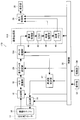
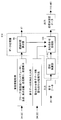
- FIG. 1 is a block diagram conceptually showing an example of the configuration of an ultrasonic diagnostic apparatus of the present invention. It is a conceptual diagram for demonstrating an example of the reception focus process in the ultrasonic diagnosing device shown in FIG. It is a block diagram which shows notionally an example of a structure of the element data process part of the ultrasonic diagnosing device shown in FIG. 4 (a) and 4 (c) are conceptual diagrams for explaining transmission / reception of an ultrasonic wave by an ideal ultrasonic beam, respectively.
- FIG. 4 (b) and FIG. It is a conceptual diagram which shows the element data obtained by transmission / reception of an ultrasonic wave.
- FIGS. 5 (a) and 5 (c) are conceptual diagrams for explaining transmission / reception of ultrasonic waves by an actual ultrasonic beam, respectively, and FIGS. 5 (b) and 5 (d) are diagrams illustrating the respective ultrasonic waves.
- It is a conceptual diagram which shows the element data obtained by transmission / reception of a sound wave.
- 6 (a) and 6 (b) are conceptual diagrams for explaining the path of a sound wave when ultrasonic waves are transmitted and received by different central elements with respect to the same reflection point.
- FIG. 6C is a conceptual diagram for explaining the element data obtained by a plurality of elements
- FIG. 6D is a conceptual diagram for explaining the delay time of the element data shown in FIG. 7 (a), 7 (b) and 7 (c) are true signals, and FIG.
- FIG. 7G is a conceptual diagram for explaining a delay time and an overlap state of element data.
- FIG. 7G shows an overlap state of element data corresponding to a plurality of elements, and
- FIG. It is a conceptual diagram for demonstrating each the result of superimposition of the element data in g).
- FIGS. 8A to 8C are conceptual diagrams for explaining the relationship between the transmission frequency and the time difference of superposition. It is a conceptual diagram for demonstrating the time difference of the reception time between element data.
- 2 is a flowchart for explaining the operation of the ultrasonic diagnostic apparatus shown in FIG. It is a block diagram which shows notionally another example of a structure of the ultrasonic diagnosing device of this invention.
- FIGS. 16A to 16C are diagrams for explaining the phasing addition and superposition processing of the data processing unit shown in FIG.
- FIG. 1 is a block diagram conceptually showing an example of the ultrasonic diagnostic apparatus of the present invention that implements the signal processing method of the present invention.
- the ultrasonic diagnostic apparatus 10 includes an ultrasonic probe 12, a transmission unit 14 and a reception unit 16 connected to the ultrasonic probe 12, a frequency setting unit 17, and an A / D conversion unit 18.
- An element data storage unit 20 an element data processing unit 22, an image generation unit 24, a display control unit 26, a display unit 28, a control unit 30, an operation unit 32, and a storage unit 34.
- the transmission unit 14, the reception unit 16, the frequency setting unit 17, the A / D conversion unit 18, the element data storage unit 20, the element data processing unit 22, the image generation unit 24, the display control unit 26, and the display unit 28 are illustrated.
- the control unit 30, the operation unit 32, and the storage unit 34 constitute an apparatus main body of the ultrasonic diagnostic apparatus 10.
- the ultrasonic probe (ultrasonic probe) 12 is a known ultrasonic probe used in a normal ultrasonic diagnostic apparatus.
- the ultrasonic probe 12 (hereinafter referred to as the probe 12) has a transducer array 36 in which ultrasonic transducers are arranged one-dimensionally or two-dimensionally.
- the ultrasonic transducer transmits an ultrasonic beam to the subject in accordance with a drive signal supplied from the transmission unit 14 at the time of imaging an ultrasonic image of an object to be examined (hereinafter referred to as a subject).
- the reflected ultrasonic echo is received, and a reception signal corresponding to the intensity of the received ultrasonic wave is output.
- the probe 12 is a probe capable of switching the ultrasonic transmission frequency, and transmits an ultrasonic beam at the transmission frequency set by the frequency setting unit 17.
- Each ultrasonic transducer includes, for example, a piezoelectric ceramic represented by PZT (lead zirconate titanate), a polymer piezoelectric element represented by PVDF (polyvinylidene fluoride), and PMN-PT (magnesium niobate / lead titanate). It is composed of a vibrator in which electrodes are formed at both ends of a piezoelectric body made of a piezoelectric single crystal typified by a solid solution).
- PZT lead zirconate titanate
- PVDF polyvinylidene fluoride
- PMN-PT magnesium niobate / lead titanate
- the piezoelectric body When a pulsed or continuous wave voltage is applied to the electrodes of such a vibrator, the piezoelectric body expands and contracts in accordance with the applied voltage, and a pulsed or continuous wave ultrasonic wave is generated from each vibrator. Further, the ultrasonic waves generated from the respective transducers are converged and synthesized (that is, transmitted and focused) at a set focal point according to the driving delay of the respective transducers, thereby forming an ultrasonic beam. The vibrator expands and contracts when an ultrasonic echo reflected in the subject is incident, and generates an electrical signal corresponding to the magnitude of the expansion and contraction. This electrical signal is output to the receiving unit 16 as a received signal (analog element signal).
- the probe 12 only needs to be configured to be able to switch between a plurality of predetermined different transmission frequencies.
- the probe 12 is configured to be able to switch between transmission frequencies of 2 MHz, 8 MHz, and 14 MHz.
- the transmission unit 14 includes, for example, a plurality of pulsers, and supplies a drive signal (applies a drive voltage) to each ultrasonic transducer (vibrator) of the probe 12.
- the transmission unit 14 is driven based on the transmission delay pattern selected by the control unit 30 so that the ultrasonic waves transmitted from the predetermined number (multiple) of ultrasonic transducers form an ultrasonic beam that converges to the set focal point.
- Transmission focus for adjusting the signal delay amount (application timing of the drive voltage) is performed, and the drive signal is supplied to the ultrasonic transducer.
- a target ultrasonic beam is transmitted from the probe 12 (the transducer array 36) to the subject.
- the reception unit 16 receives reception signals output from a predetermined number (multiple) of ultrasonic transducers corresponding to one transmission of the ultrasonic beam, and performs predetermined processing such as amplification. Is supplied to the A / D converter 18.
- the method of transmitting and receiving ultrasonic waves is basically the same as that of a known ultrasonic diagnostic apparatus. Accordingly, the number of ultrasonic transducers (the number of transmission apertures) that generate ultrasonic waves in one ultrasonic transmission / reception (transmission of one ultrasonic beam and reception of ultrasonic echoes corresponding to this transmission).
- the number of ultrasonic transducers (the number of reception apertures) that receive ultrasonic waves (the reception unit 16 receives reception signals) is not limited as long as both are plural. In one transmission / reception, the numerical aperture may be the same or different between transmission and reception.
- the number of transmission / reception of ultrasonic waves for forming one ultrasonic image There is no limitation on (number of sound rays) and the interval between ultrasonic transducers (center elements) that is the center of transmission / reception (that is, scanning line / sound ray density). Accordingly, ultrasonic transmission / reception may be performed using all ultrasonic transducers corresponding to the region scanned with ultrasonic waves as a central element, and ultrasonic transducers at predetermined intervals such as every second or every four ultrasonic transducers may be used as a central element. Sound waves may be transmitted and received. Similarly to known ultrasonic diagnostic apparatuses, in order to form one ultrasonic image, transmission / reception positions are sequentially moved and transmission / reception is performed at a plurality of positions (lines).
- the frequency setting unit 17 transmits an ultrasonic wave according to the condition of element data superimposition processing in the element data processing unit 22 to be described later, specifically, the time difference of the reception time between the element data to be superimposed. Determine the transmission frequency. A method of determining the transmission frequency in the frequency setting unit 17 will be described in detail later.
- the frequency setting unit 17 supplies the set transmission frequency information to the transmission unit 14.
- the A / D conversion unit 18 performs analog / digital conversion on the analog reception signal supplied from the reception unit 16 to obtain element data (first element data) that is a digital reception signal.
- the A / D converter 18 supplies the A / D converted element data to the element data storage unit 20.
- the element data storage unit 20 sequentially stores the element data supplied from the A / D conversion unit 18.
- the element data storage unit 20 associates information about the frame rate input from the control unit 30 (for example, parameters indicating the depth of the reflection position of the ultrasonic wave, the density of the scanning line, and the field width) with each element data.
- the element data storage unit 20 stores all element data corresponding to at least one ultrasonic image (one frame of ultrasonic image) and displays at least until the display of the ultrasonic image is finished. The element data of the ultrasonic image before and during display is not erased.
- the element data processing unit 22 is a part that superimposes element data and generates processed element data (second element data) corresponding to each element data. Specifically, the element data processing unit 22 is based on the control by the control unit 30, and among the element data stored in the element data storage unit 20, a central ultrasonic transducer (center element (center element)).
- the element data obtained by transmitting a predetermined number (multiple) of ultrasonic beams, the time when each ultrasonic transducer receives the ultrasonic echo, and the ultrasonic data Processed element data corresponding to element data (element data of a target element to be described later) is generated by superimposing according to the position of the acoustic wave transducer.
- the processing in the element data processing unit 22 will be described in detail later.
- the element data processing unit 22 sends the generated processed element data to the image generation unit 24.
- the image generation unit 24 generates reception data (sound ray signal) from the processed element data supplied from the element data processing unit 22 based on control by the control unit 30, and generates an ultrasonic image from the reception data. Is.
- the image generation unit 24 includes a phasing addition unit 38, a detection processing unit 40, a DSC 42, an image processing unit 44, and an image memory 46.
- the phasing / adding unit 38 performs matching processing on the processed element data generated by the element data processing unit 22 and performs reception focus processing to generate reception data.
- the transducer array 36 of the probe 12 is formed by arranging a plurality of elements (ultrasonic transducers) one-dimensionally or two-dimensionally. Therefore, the distance between one reflection point in the subject is different for each ultrasonic transducer. Therefore, even when the ultrasonic echoes are reflected at the same reflection point, the time for the ultrasonic echoes to reach each ultrasonic transducer is different.
- the phasing addition unit 38 corresponds to the difference (delay time) in the arrival time of ultrasonic echoes for each ultrasonic transducer in accordance with the reception delay pattern selected by the control unit 30.
- the received element processing is digitally performed by matching and adding the processed element data to which the delay time is given, and reception data is generated.
- the phasing addition unit 38 supplies the generated reception data to the detection processing unit 40.
- FIG. 2 shows an example of the reception focus process.
- FIG. 2 is a case of a linear probe in which a plurality of ultrasonic transducers of the probe 12 are arranged in a line in the left-right direction in FIG.
- the idea may be the same except that the probe shape is different.
- each ultrasonic transducer in the azimuth direction is L
- the distance from the ultrasonic transducer at the center in the azimuth direction to the nth ultrasonic transducer toward the end is nL.
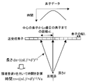
- the reflection point of the ultrasonic wave is at a position (depth) d perpendicular to the arrangement direction from the central ultrasonic transducer, the nth ultrasonic transducer, the reflection point, and the distance (length) d n between, is calculated by the equation (1).
- t n ((nL) 2 + d 2 ) 1/2 (1) Accordingly, the time t n for the ultrasonic echo to reach (receive) the nth ultrasonic transducer from the reflection point using the ultrasonic sound velocity (environmental sound velocity) Va in the subject is calculated by the equation (2).
- the distance between the ultrasonic transducer and the reflection point is different for each ultrasonic transducer. Therefore, in the case of this example, as shown in the upper graph, the arrival time t n of the ultrasonic echo becomes longer as the ultrasonic transducer on the end side in the arrangement direction becomes longer.
- this delay time ⁇ t is a reception delay pattern.
- the phasing adder 38 performs phasing addition on the signals corresponding to the respective ultrasonic transducers using the delay time represented by the time ⁇ t, performs reception focus processing, and generates reception data.
- the detection processing unit 40 corrects attenuation according to the distance according to the depth of the reflection position of the ultrasonic wave on the reception data generated by the phasing addition unit 38, and then performs envelope detection processing to thereby detect the subject.
- B-mode image data that is image information (luminance image information) of a tomogram in the inside is generated.
- a DSC (digital scan converter) 42 converts the B-mode image data generated by the detection processing unit 40 into image data corresponding to a normal television signal scanning method (raster conversion).
- the image processing unit 44 performs various necessary image processing such as gradation processing on the B-mode image data input from the DSC 42 to obtain B-mode image data for display.
- the image processing unit 44 outputs the image-processed B-mode image data to the display control unit 26 for display and / or stores it in the image memory 46.
- the image memory 46 is a known storage unit (storage medium) that stores the B-mode image data processed by the image processing unit 44.
- the B-mode image data stored in the image memory 46 is read to the display control unit 26 for display on the display unit 28 as necessary.
- the display control unit 26 causes the display unit 28 to display an ultrasonic image using the B-mode image data that has been subjected to predetermined image processing by the image processing unit 44.
- the display unit 28 includes a display device such as an LCD, for example, and displays an ultrasonic image under the control of the display control unit 26.
- the control unit 30 is a part that controls each unit of the ultrasonic diagnostic apparatus 10 based on a command input from the operation unit 32 by the operator.
- the control unit 30 supplies various types of information input by the operator using the operation unit 32 to necessary parts. For example, in the operation unit 32, information necessary for transmission frequency setting used in the frequency setting unit 17, information necessary for delay time calculation used in the element data processing unit 22 and the phasing addition unit 38 of the image generation unit 24, and When information necessary for element data processing in the element data processing unit 22 is input, the information is transmitted to the transmission unit 14, the reception unit 16, the frequency setting unit 17, and the element data storage as necessary. The data is supplied to each unit such as the unit 20, the element data processing unit 22, the image generation unit 24, and the display control unit 26.
- the operation unit 32 is for an operator to perform an input operation, and can be formed from a keyboard, a mouse, a trackball, a touch panel, and the like.
- the operation unit 32 also has an input function for the operator to input various types of information as necessary.
- the operation unit 32 includes information on generation of processed element data such as information on the probe 12 (ultrasonic transducer), transmission aperture and reception aperture in the probe 12 (transducer array 36), the number of element data to be superimposed and the method,
- An input function for inputting the focal position of the ultrasonic beam is provided. These are input, for example, by selecting an imaging region (examination region), selecting an image quality, selecting a depth of an ultrasonic image to be captured, and the like.
- the storage unit 34 includes an operation program for the control unit 30 to control each unit of the ultrasonic diagnostic apparatus 10, transmission delay pattern and reception delay pattern, information on generation of processed element data, and further from the operation unit 32.
- the control unit 30 stores information necessary for the operation and control of the ultrasonic diagnostic apparatus, such as the input probe 12 information, transmission aperture and reception aperture, and focal position information.
- the storage unit 34 may be a known recording medium such as a hard disk, flexible disk, MO, MT, RAM, CD-ROM, DVD-ROM or the like.
- the frequency setting unit 17, the element data processing unit 22, the phasing addition unit 38, the detection processing unit 40, the DSC 42, the image processing unit 44, the display control unit 26, and the like are a CPU and a CPU. Is composed of an operation program for causing the computer to perform various processes. However, in the present invention, these parts may be constituted by digital circuits.
- the element data processing unit 22 differs from the element data (unprocessed element data) stored in the element data storage unit 20 in that the central ultrasonic transducer (center element) is different, and the ultrasonic beam.
- the element data obtained by transmitting a predetermined number (plurality) of ultrasonic beams that overlap the transmission areas of each other are superimposed according to the time received by each ultrasonic transducer and the position of the ultrasonic transducer, and processed element data It is a part which produces
- the ultrasonic transducer is also simply referred to as “element”.
- FIG. 3 conceptually shows the configuration of the element data processing unit 22 in a block diagram.
- the element data processing unit 22 includes a delay time calculation unit 48 and an overlay processing unit 49.
- the delay time calculation unit 48 receives the probe 12 (ultrasonic transducer (element)) input from the operation unit 32 or input from the operation unit 32 and stored in the storage unit 34, the focal position of the ultrasonic beam, Information regarding the position of the sampling point (element data output position), the transmission aperture and the reception aperture of the probe 12, and the like are acquired in advance.
- the delay time calculation unit 48 also includes a geometrical arrangement of a transmission aperture element that oscillates an ultrasonic wave to transmit (generate) an ultrasonic beam and a reception aperture element that receives an ultrasonic echo from the subject. Based on the correct position, the delay time of the ultrasonic echo received by the element of the reception aperture, that is, the element data is calculated.
- the delay time calculation unit 48 calculates the delay time before transmitting / receiving ultrasonic waves, and supplies the delay time to the frequency setting unit 17.
- the delay time calculation unit 48 supplies the calculated delay time information to the overlay processing unit 49 and the frequency setting unit 17.
- the overlay processing unit 49 relates to element data processing such as the number of element data to be superimposed and the overlay processing method, which are input from the operation unit 32 or input from the operation unit 32 and stored in the storage unit 34. Based on the information, element data to be superposed from element data stored in the element data storage unit 20 (element data obtained by an ultrasonic beam having different central elements and overlapping transmission areas (two or more element data). Read two or more element data generated for each target area)). Furthermore, the superimposition processing unit 49 receives two or more element data on the reception time, that is, by matching the time based on the delay time corresponding to each element data calculated by the delay time calculation unit 48. And the absolute position of the received element of the probe is matched and superposed to generate processed element data.
- element data processing such as the number of element data to be superimposed and the overlay processing method
- an ultrasonic beam is transmitted to a subject from a transmission aperture, that is, an element that transmits an ultrasonic wave to transmit an ultrasonic beam (hereinafter simply referred to as a transmission element).
- a transmission element that transmits an ultrasonic wave to transmit an ultrasonic beam
- the receiving element receives the ultrasonic echo
- the ultrasonic wave from the transmitting element
- an ultrasonic beam is transmitted using three elements 52c to 52e as transmitting elements, and an ultrasonic echo is received using seven elements 52a to 52g as receiving elements.
- the element is moved in the azimuth direction by one element (hereinafter also referred to as a shift), and an ultrasonic beam is transmitted using the three elements 52d to 52f as transmitting elements.
- the ultrasonic echoes are received by using the two elements 52b to 52h as receiving elements, and element data is acquired respectively. That is, in the example shown in FIG. 4A, the central element (the central element) is the element 52d, and in the example shown in FIG. 4C, the central element is the element 52e.
- the ultrasonic beam 56 to be transmitted to the inspection target region including the reflection point 54 is converged at the focal point 58 and narrowed to the element interval or less.
- the ultrasonic beam 56 is transmitted from the elements 52c to 52e serving as transmitting elements, with the element 52d located directly above the reflecting point 54 (on the straight line connecting the reflecting point and the focal point) as the central element.
- the focal point 58 of the ultrasonic beam 56 is on a straight line connecting the element 52d as the central element and the reflection point 54.
- the ultrasonic beam 56 is transmitted to the reflection point 54, an ultrasonic echo reflected from the reflection point 54 is generated.
- the ultrasonic echoes from the reflection point 54 are received by the elements 52a to 52g as the receiving elements through the receiving path 60 spreading at a predetermined angle, and the element data 62 as shown in FIG. 4B is received by the elements 52a to 52g. Is obtained.
- the vertical axis represents time
- the horizontal axis represents the position in the azimuth direction (element position) coinciding with FIG. 4A (the same applies to FIG. 4D).
- the ultrasonic beam 56 is transmitted from the elements 52d to 52f which are transmitting elements, and ultrasonic echoes are received by the elements 52b to 52h which are receiving elements.
- the reflection point 54 does not exist on the transmission direction of the ultrasonic beam 56, that is, on the straight line connecting the center element 52 e and the focal point 58. Therefore, the ultrasonic beam 56 is not transmitted to the reflection point 54.
- the element data does not include the reflection signal from the reflection point (the signal intensity of the element data becomes “0”).
- the width is wider than the element spacing.
- the ultrasonic beam 64 is transmitted using the element 52d immediately above the reflection point 54 as the central element and the elements 52c to 52e as the transmitting elements.
- the focal point 58 is on a straight line connecting the element 52 d and the reflection point 54. Accordingly, the ultrasonic beam 64 is reflected at the reflection point 54, and an ultrasonic echo is generated.
- the ultrasonic echo from the reflection point 54 is received by the elements 52a to 52g as the receiving elements through the receiving path 60 spreading to a predetermined angle.
- True element data 66 as shown in FIG. 5B is obtained.
- the central element is shifted by one element, the adjacent element 52e is used as the central element, and the elements 52d to 52f are used as the transmitting elements.
- the beam 56 is transmitted, and ultrasonic echoes are received using the elements 52b to 52h as receiving elements.
- the ultrasonic beam 64 is wide, even if the reflection point 54 does not exist on the transmission direction of the ultrasonic wave, that is, on the straight line connecting the element 52e as the central element and the focal point 58, the ultrasonic beam 64
- the sound beam 64 is transmitted (arrives) to the reflection point 54.
- an ultrasonic echo that does not originally exist that is, a so-called ghost reflection echo is generated from the reflection point 54 in the transmission direction of the ultrasonic beam.
- the ghost reflection echo from the reflection point 54 is received by the elements 52b to 52h, which are reception elements, through the reception path 60 that spreads to a predetermined angle.
- ghost element data 68 as shown in FIG. 5D is obtained by the elements 52b to 52h.
- Such ghost element data 68 causes a decrease in the accuracy of the ultrasonic image generated from the element data.
- the element data processing unit 22 calculates a delay time corresponding to the element data by the delay time calculation unit 48, and the overlay processing unit 49 determines that the two or more element data correspond to the delay time and the absolute position of the element. By superimposing, processed element data that is highly accurate element data in which true element data is emphasized and a ghost signal is attenuated is generated.
- the delay time calculation unit 48 calculates the delay time of the element data received by each element of the reception element (reception aperture). That is, the propagation distance of the ultrasonic beam 64 shown in FIG. 5C is such that the transmission path from the element 52e, which is the central element of the ultrasonic beam 64, to the reflection point 54 via the focal point 58, and the reflection echo of the ghost. This is the sum of the reception path from the reflection point 54 to each of the elements 52b to 52h, which are reception elements.
- the propagation distance of the ultrasonic beam 64 shown in FIG. 5C is the propagation distance of the ultrasonic beam 64 shown in FIG. 5A, that is, the ultrasonic beam 64 is reflected from the central element 52d via the focal point 58.
- the transmission path to the point 54 and the true ultrasonic echo are longer than the sum of the reception path from the reflection point 54 to the receiving elements 52a to 52g. For this reason, the ghost element data 68 as shown in FIG. 5D is delayed with respect to the true element data 66 as shown in FIG. 5B.
- the delay time calculation unit 48 of the element data processing unit 22 the time difference between the ghost element data and the true element data, that is, the delay time is the speed of sound, the transmission element, the focus of the ultrasonic beam, the reflection point of the subject, and the reception element. It is calculated from the geometric arrangement of Therefore, the calculation of the delay time requires information such as the shape of the probe 12 (element spacing, linear, convex, etc.), sound speed, focal position, transmission aperture, and reception aperture.
- the delay time calculation unit 48 obtains the information input by the operation unit 32 or stored in the storage unit 34, and calculates the delay time.
- the sound speed may be a fixed value (for example, 1540 m / sec), or when the sound speed calculation unit is provided, the sound speed (environmental sound speed) calculated by the sound speed calculation unit may be used, or The operator may be able to input.
- the delay time is calculated from, for example, the geometrical arrangement of the transmission element, the focal point of the ultrasonic beam, the reflection point of the subject, and the reception element, and the transmission path of the ultrasonic beam from the transmission element to the reflection point through the focal point. And the total length (propagation distance) of the reception path of the true reflected ultrasonic echo or ghost reflected signal from the reflection point to the receiving element, and the difference between the propagation times calculated by the sound speed.
- the lengths of the transmission path and the reception path of the ultrasonic beam in the case of a true ultrasonic echo and a ghost reflection echo are obtained.
- the x direction is the azimuth direction
- the y direction is the depth direction. 6A performs transmission / reception of ultrasonic waves similar to FIG. 5A
- FIG. 6B performs transmission / reception of ultrasonic waves similar to FIG. 5C.
- the element 52d which is the central element, the focal point 58, and the reflection point 54 are located on a straight line. (The azimuth position is the same.) That is, the focal point 58 and the reflection point 54 are located directly below the central element 52d. Therefore, if the position of the element 52d as the central element is the coordinates (x0, 0) on the xy two-dimensional coordinates, the x coordinates of the focal point 58 and the reflection point 54 are also “x0”.
- the position of the focal point 58 in this transmission is set to coordinates (x0, df)
- the position of the reflection point 54 is set to coordinates (x0, z)
- the element interval is set to Le.
- the transmitting element and the receiving element are shifted by one element in the x direction (azimuth direction) (shifted to the right in the figure), and transmission / reception is performed using the central element as the element 52e. .
- FIG. 5C in this case, what is reflected at the reflection point 54 is a ghost reflection echo.
- the reflection point 54 is located directly below the element 52d (the same position in the azimuth direction). Therefore, as shown in FIG. 6B, in this transmission / reception, the position in the x direction between the element 52e as the central element and the reflection point 54 is shifted in the x direction by one element, that is, Le.
- the coordinate of the element 52d whose position in the x direction coincides with the reflection point 54 is (x0, 0)
- the coordinate of the element 52e as the central element is (x0 + Le, 0)
- the coordinate of the focal point 58 in this transmission is (x0 + Le). , Df).
- the coordinates of the reflection point 54 are (x0, z).
- a value obtained by dividing the ultrasonic propagation distance Lua which is the sum of the distance Lta of the transmission path 61 and the distance Lra of the reception path 60, obtained by the geometric arrangement shown in FIG. This is the echo propagation time.
- the value obtained by dividing the ultrasonic propagation distance Lub which is the sum of the distance Ltb of the transmission path 61 and the distance Lrb of the reception path 60 obtained by the geometric arrangement shown in FIG. Propagation time.
- the delay time is obtained when the x coordinate between the reflection point 54 and the central element is shifted by one element interval from the propagation time of the true ultrasonic echo when the x coordinate between the reflection point 54 and the central element coincides.
- the transmission path 61 is a model passing through the focal point 58.
- the present invention is not limited to this, and for example, via the focal point 58. Instead, the path directly reaching the reflection point 54 may be used.
- FIG. 6A and FIG. 6B is a case of a linear probe, not only this but the other geometrical calculation can be performed from the shape of a probe. .
- a geometric model can be set from the probe radius and the element spacing angle, and the calculation can be performed in the same manner.
- the delay time is not limited to the method of calculating the delay time using the geometric model, and the delay time is obtained for each measurement condition from the measurement result obtained by measuring the high-intensity reflection point according to the measurement condition of the apparatus in advance. By storing in the apparatus, the delay time of the same measurement condition may be read out.
- FIG. 6C shows true element data 66 and ghost element data 68.
- the center of the azimuth direction is true element data 66, that is, element data obtained by transmission / reception in which the center element and the reflection point 54 have the same position in the x direction (in the illustrated example, Element data with the element 52d as the central element).
- ghost element data on both sides of the center that is, element data obtained by transmission / reception in which the positions of the central element and the reflection point 54 do not coincide with each other in the x direction (in the illustrated example, element data 52c, element 52e, etc. Element data as a central element).
- FIG. 6D shows an example of the delay time of the ghost element data 68 with respect to the true element data 66 obtained from the above-described geometric calculation. It is shown that the element data 68 of the ghost signal is symmetrically delayed in the x direction, that is, the azimuth direction, with the true element data 66 as the center. In this way, the delay time calculated by the delay time calculation unit 48 of the element data processing unit 22 can also be used for delay correction in the phasing addition unit 38.
- the element data obtained by transmitting an ultrasonic beam having a certain element of interest as the central element is different from the central element, and the ultrasonic beam
- the element data obtained by transmitting at least a part of the overlapping ultrasonic beam is overlapped with the reception time of the ultrasonic echo and the position of the element so as to superimpose the processed element data (second element) of the element of interest.
- Data (reconstruct the element data of the element of interest).
- the reflection point 54 is a position of a certain sampling point (element data output position) located directly below the target element (same position in the azimuth direction / on a straight line connecting the target element and the focal point).
- the transmission / reception path to the sampling point in the transmission / reception of the element of interest is regarded as the transmission / reception path of the true element data, and the transmission / reception path to the same sampling point in the transmission / reception of ultrasonic waves with different central elements (transmission / reception from peripheral elements)
- a delay time is calculated from the difference between the two transmission paths, and the element data time is combined using this delay time to perform superposition.
- a delay time with element data by transmission / reception with different central elements may be calculated for each sampling point in the depth direction (y direction).
- the overlay processing of the element data is performed using the delay time thus calculated by the delay time calculating section 48.
- the overlay processing in the overlay processing unit 49 requires information on the number of superimposing element data and the overlay processing method at the time of overlaying, but these may be input in advance by the operation unit 32. It may be stored in the storage unit 34.
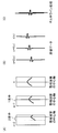
- FIG. 7A to FIG. 7H show an example of the overlay process performed by the overlay processor 49.
- the examples shown in FIGS. 7A to 7H are cases where the number of element data is five and the number of overlapping element data is three.
- FIG. 7A shows five element data obtained by transmitting and receiving five ultrasonic waves side by side.
- FIG. 7A shows a state where an ultrasonic beam is transmitted and an ultrasonic echo is received for each element data.
- the horizontal axis of each element data represents a receiving element, and the respective element data are displayed centering on the central element in transmission / reception of the ultrasonic beam.
- the vertical axis represents the reception time.
- the ultrasonic wave is transmitted and received five times by shifting the central element, such as the elements 52b to 52f, one element at a time.
- FIG. 7A shows a state in which one reflection point exists only directly below the central element in the central element data. That is, among the five element data, in the middle element data, a true ultrasonic echo from the reflection point is received in transmission / reception of ultrasonic waves. That is, the middle element data is true element data.
- the reflected echo element data that is, the ghost element data
- the propagation time of the ultrasonic wave to the reflection point becomes longer, so that the reception time becomes slower than the true element data.
- the position of the receiving element where the ultrasonic echo from the reflection point is first received is the element immediately above the reflection point (the element whose position in the azimuth direction coincides with the reflection point).
- each element data in FIG. 7A is centered on the central element at the time of transmission of the ultrasonic beam. Therefore, in the example shown in FIG. 7A, since the central element is shifted by one element for each element data, the absolute position of the element in the azimuth direction is shifted by one element in each element data. ing. That is, in the middle element data, the receiving element from which the reflected signal from the reflection point is first received is the central element. However, in the adjacent element data, one element is shifted from the middle element data. The element data is shifted one element to the left, and the element data on the left is shifted one element to the right.
- the element data at both ends are shifted by two elements from the middle element data, the leftmost element data is shifted two elements to the left, and the leftmost element data is shifted two elements to the right.
- the ghost signal is not only delayed in reception time with respect to the true signal, but also deviated from the direction of the receiving element.
- FIG. 7B shows an example of the delay time of the reception time for the middle element data among the five element data shown in FIG.
- the delay time is corrected by three element data, and each element data is changed according to the element position difference from the element of interest (the difference in position between the central elements).
- Each element is shifted in the azimuth direction, that is, the unprocessed element data corresponding to the three element data is superposed by matching the phase, and is obtained as one superposed processed element data of the element of interest.
- the element data obtained by transmission / reception of the ultrasonic wave with the target element as the central element (hereinafter also referred to as element data of the target element) is the ultrasonic wave with the element adjacent to the target element as the central element.
- the element data obtained by the transmission / reception (hereinafter also referred to as element data of the adjacent element) is superimposed to generate processed element data of the element data of the element of interest.
- FIG. 7 (c) shows the element-processed element data of the target element thus obtained.
- the element data of the target element shown in FIG. 7A is true element data in which a reflection point exists immediately below the central element (that is, the target element).
- element data obtained by transmission / reception using an element adjacent to the element of interest as a central element is also data of reflected ultrasonic echoes incident on the reflection point. Therefore, when the element data of the adjacent element on both sides of the element data of the element of interest is subjected to delay time correction and azimuth shift to perform phase matching, as shown in FIG. And the element data of the element of interest overlap at a high luminance position because the phases match. Therefore, when these element data are added, for example, the element data value shows a large value (high luminance value), and for example, even if an average value is obtained by averaging, an emphasized value (high luminance value) is shown.
- FIG. 7 (d) shows an example in which the element data is the same as that in FIG. 7 (a), but the central element of the element data on the left side of the middle element data is the target element. That is, this example shows an example of the case where the central element is the element of interest in the transmission / reception of ultrasonic waves with the element having no reflection point directly below as the central element. Therefore, element data having this element as a central element is ghost element data.
- FIG. 7 (e) is the same as FIG. 7 (b), and shows an example of the delay time of the reception time for the element data of the target element of the five element data shown in FIG. 7 (a). That is, since FIG. 7A and FIG.
- the delay time shown in FIG. 7E (that is, the same as FIG. 7B) is used for the number of overlay element data, centering on the element data of the element of interest.
- the delay time is corrected by three element data, and each element data is set to one element each on both sides in the illustrated example in accordance with the difference in element position with respect to the element of interest (difference in position between central elements). Shifting in the azimuth direction, the unprocessed element data corresponding to the three element data is overlaid and obtained as one overlaid processed element data of the element of interest.
- FIG. 7 (f) shows element data obtained by superimposing the target element obtained in this way.
- the element data of the element of interest shown in FIG. 7D is ghost element data. Therefore, even if the phase adjustment is performed by performing the delay time correction and the azimuth direction shift on the unprocessed element data of the adjacent element on both sides of the element data of the element of interest, as shown in FIG.
- the element data and the element data of the target element do not overlap because the phases do not match each other. For this reason, even if these three element data are added, for example, since the phases are not matched, signals that are inverted in phase cancel each other out, so the added value does not increase. When the average value is obtained, a small value is shown.
- FIG. 7H shows the result of, for example, addition processing or averaging processing as overlay processing.
- FIG. 7 (h) when a central element having a reflection point immediately below shown in FIG. 7 (a) is used as a target element, the true signal element data has a high luminance value. It is obtained as combined element data.
- element data whose phases are not matched with each other are added to the ghost element data or averaged.
- the element data will cancel each other, so that the ghost superposition processed element data is compared with the superposition processed element data having a high luminance value whose value is the element data of the true signal.
- the influence of the ghost element data on the true element data can be reduced, or the influence can be reduced to the extent that the influence can be ignored.
- a certain element is used as an element of interest, and the element data (element data of the element of interest) obtained by transmission of an ultrasonic beam using the element of interest as a central element is different from the central element, and transmission of an ultrasonic beam is performed.
- the element data obtained by transmitting and receiving ultrasonic waves with overlapping regions by performing time and azimuth alignment, and generating processed element data corresponding to the element data of the element of interest ( In other words, by reconstructing (correcting) the element data of the element of interest using element data by transmission and reception with at least a part of the ultrasonic beam overlapping and different central elements), the true element data is increased. Brightness and ghost element data can be reduced.
- phasing addition and detection processing are performed on the processed element data, reception data is generated, and ultrasonic images are generated, thereby eliminating the influence of ghosts, that is, focusing on all points on the sound ray. Since an ultrasonic image can be generated with the same element data, it is possible to generate a high-quality ultrasonic image with high brightness and excellent sharpness.
- the generation of processed element data is also referred to as multiline processing.
- the central element is an element at the center in the azimuth direction when the numerical aperture for transmission (the number of elements for transmitting ultrasonic waves) is an odd number.
- the numerical aperture is an even number
- one of the central elements in the azimuth direction is set as the central element, or the central element is assumed to be in the middle of the azimuth direction. That is, when the numerical aperture is an even number, the calculation may be performed assuming that the focal point is on the middle line of the aperture.
- the superimposition processing method in the superimposition processing unit 49 is not simply the addition, but may be an average value or a median value, or may be performed after multiplication by coefficients. Note that taking an average value or median value is thought to correspond to applying an averaging filter or median filter at the element data level, but is performed by normal image processing instead of the averaging filter or median filter. An inverse filter or the like may also be applied. Alternatively, each element data to be overlapped is compared, and if they are similar, the maximum value is taken, if not, the average value is taken, and if there is a distribution bias, the intermediate value is taken. The overlay process may be changed based on the feature amount of each element data to be superimposed.
- the number of element data to be superimposed on the element data of the element of interest is not limited to two in the illustrated example, and may be one or three or more. That is, the number of element data to be superimposed on the element data of the element of interest may be appropriately set according to the required processing speed (frame rate or the like), image quality, and the like.
- the number of element data to be superimposed on the element data of the element of interest matches the extent of the beam width of the ultrasonic beam. Therefore, when the beam width changes depending on the depth, the number of element data to be superimposed may be changed depending on the depth. Further, since the beam width depends on the transmission numerical aperture, the number of element data to be superimposed may be changed according to the transmission numerical aperture.
- the number of overlapping element data may be changed based on the feature value such as the luminance value of the image, or the optimum number of overlapping element data is selected from images created by changing the number of overlapping element data in multiple patterns. May be.
- the processed element data of the element data of the element of interest is generated, the present invention is not limited to this.
- the processed element data may be generated by superimposing element data obtained by transmitting a plurality of ultrasonic beams having different transmission directions (angles) with the same central element.
- which element data obtained by transmission of the ultrasonic beam to generate processed element data depends on the examination site and the probe.
- Processed element data may be generated.
- the element data processing unit 22 sends the generated processed element data to the image generation unit 24 (phasing addition unit 38).
- the phasing addition unit 38 performs phasing addition on the processed element data, performs reception focus processing, and generates reception data.
- 40 generates B-mode image data by performing attenuation correction and envelope detection processing on the received data.
- the DSC 42 raster-converts the B-mode image data into image data corresponding to a normal television signal scanning method, and the image processing unit 44 performs predetermined processing such as gradation processing.
- the image processing unit 44 stores the generated B-mode image data in the image memory 46 and / or sends it to the display control unit 26 to display the B-mode image of the subject on the display unit 28.
- the transmission frequency setting method in the frequency setting unit 17 will be described in more detail.
- the relationship between the transmission frequency of ultrasonic waves and the time difference between element data superimposed (ghost) in the overlay processing unit 49 will be described.
- the superposition of two element data will be described.
- FIG. 8A the element data on the left side of the element data group shown in FIG. Is. That is, it is a diagram showing a state in which the delay time correction is performed on the element data on the left side, and the two element data are overlapped by shifting in the surrounding direction by one element.
- the element data of the target element in FIG. 8A is ghost element data, even if phase adjustment is performed by performing delay time correction and azimuth direction shift, adjacent elements
- the element data of the element and the element data of the element of interest do not overlap each other because the phases do not match each other.
- FIG. 8B and FIG. 8C are diagrams schematically showing a signal on a line (line of the central element) indicated by a broken line in FIG. That is, in FIGS. 8B and 8C, the horizontal axis represents time, and the vertical axis represents signal intensity.
- FIG. 8B shows a case where the half cycle of the ultrasonic wave is a transmission frequency shorter than the time difference of the reception time between the element data to be superimposed.
- FIG. 8C shows a case where the half-cycle of the ultrasonic wave has a transmission frequency longer than the time difference in reception time between the element data to be superimposed.
- the phase is shifted when the addition process (average process) is performed.
- the signals are attenuated as shown on the right side of the figure. That is, the ghost signal can be removed.
- the frequency setting unit 17 sets a transmission frequency whose half cycle is shorter than the time difference in accordance with the time difference of the reception time between the element data to be superimposed, and transmits information on the set transmission frequency. 14.
- a ghost signal can be appropriately removed by superimposing element data obtained by performing transmission at a set transmission frequency.
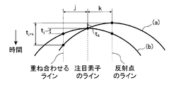
- the curve indicated by (a) in FIG. 9 shows an example of the delay time when the element immediately above the reflection point is the target element, as in FIG. 7 (b).
- the curve shown in FIG. 9B shows an example of the delay time when the element at the position shifted from the reflection point is the target element, as in FIG. 7E. It is assumed that there is a reflection point on a line having an element separated by k elements from the element of interest as a central element, and element data obtained by using an element separated from the element of interest by j elements as the central element is superimposed.
- the delay time when x elements are separated from the element of interest is t x
- the signal corresponding to the reflection point on the element data corresponding to the element of interest before the delay time correction is superimposed from curve (a).
- the time difference in reception time from the signal corresponding to the reflection point on the element data is t j + k ⁇ t k .
- the delay time t j is corrected for the element data to be superimposed using the delay time as shown in the curve (b). Therefore, the reception time of the signal corresponding to the reflection point on the element data corresponding to the element of interest and the signal corresponding to the reflection point on the element data to be superimposed after the delay time correction is performed with reference to the element of interest.
- the delay time as shown in the curves (a) and (b) of FIG. 9 is based on information such as the element interval, the focal position of the ultrasonic beam, the position of the sampling point, the transmission aperture, and the reception aperture.
- the delay time calculation unit 48 can calculate in advance. Therefore, the time difference t of the reception time between the element data to be superimposed can be calculated in advance.
- the frequency setting unit 17 includes a probe 12 (ultrasonic transducer (element)) input from the operation unit 32 or input from the operation unit 32 and stored in the storage unit 34, a focal position of the ultrasonic beam, a probe Information about 12 transmission apertures and reception apertures is acquired, and based on the delay time information supplied from the delay time calculation unit 48, a time difference t of reception times between element data to be superimposed is calculated. Next, the frequency setting unit 17 sets a transmission frequency at which a half cycle is shorter than the calculated time difference t. The frequency setting unit 17 supplies the set transmission frequency information to the transmission unit 14. The transmission unit 14 transmits an ultrasonic beam at the set transmission frequency.
- the element data processing unit 22 performs multiline processing using element data obtained by transmitting an ultrasonic beam at a set transmission frequency.
- the inventors when performing multiline processing in the ultrasonic diagnostic apparatus, the inventors appropriately superimpose if the period of the transmission frequency is large with respect to the time difference of the reception time between the superimposed data. It was not possible to perform this, and even in the case of a ghost signal, it was found that the data overlapped and emphasized and the ghost signal could not be removed.
- the ultrasonic diagnostic apparatus 10 generates a second element data corresponding to one of the first element data from a plurality of first element data, that is, when performing a multiline process.
- the transmission frequency of the ultrasonic beam is set according to the processing conditions of the multi-line processing, and a plurality of first element data obtained by transmitting the ultrasonic beam at the transmission frequency set by the frequency setting unit ( Second element data (processed element data) is generated using unprocessed element data.
- the frequency setting unit 17 selects any one of the transmission frequencies whose half cycle is shorter than the calculated time difference t. Can be set.
- any value may be used as long as the transmission frequency becomes a half cycle shorter than the calculated time difference t.
- what value should be selected may be appropriately determined according to the depth of the region to be imaged, the performance of the probe 12, the image quality of the required ultrasonic image, and the like.
- FIG. 8B when the half cycle is too short with respect to the time difference t (when the transmission frequency is too high), the peak portion of the signal and the valley portion do not overlap. Therefore, the effect of canceling the signals is reduced.
- the distance resolution increases as the transmission frequency increases, it is preferable to determine the transmission frequency in consideration of these effects.
- the time difference t of the reception time becomes smaller as the position (line) of the reflection point is closer to the line of the element of interest. Therefore, the time difference t may be obtained assuming that there is a reflection point on the line of the element adjacent to the element of interest.
- the transmission frequency may be set based on the time difference t of the reception time between any element data. From the viewpoint of image quality, it is preferable to set the transmission frequency based on the time difference t of the reception time with the element data of the element at the closest position, but a high transmission frequency is required. On the other hand, based on the time difference t from the element data of the element at the farthest position, the range of transmission frequencies that can be adopted is widened, but the effect of improving the image quality is reduced.
- the time difference between the element data changes according to the depth of the region to be viewed (the position of the sampling point in the depth direction).
- a transmission frequency having a half cycle shorter than the smallest time difference t may be employed.
- the transmission frequency may be set based on the time difference t at that depth.
- the program of the present invention is a program that causes a computer included in the ultrasonic diagnostic apparatus 10 to execute the following signal processing method.
- the recording medium of the present invention is a recording medium on which the program is recorded.
- a memory attached to a control unit or the like that stores the program may be used.
- it may be a memory medium (removable medium) configured to be detachable from the ultrasonic inspection apparatus such as a CD-ROM, and is configured to read the program into the diagnostic apparatus via an interface corresponding to the removable medium. May be.
- the delay time calculation unit 48 includes the probe 12 (element interval) input from the operation unit 32, the focal position of the ultrasonic beam, the transmission aperture, the reception aperture, the position of the sampling point, and the superposition. Based on information such as the number of element data, the delay time of the element data is calculated.
- the frequency setting unit 17 sets the transmission frequency based on the calculated delay time information.
- the transmission unit 14 drives the corresponding ultrasonic transducer (element) of the probe 12 (transducer array 36) at the set transmission frequency in order to acquire element data.
- an ultrasonic beam is transmitted to the subject, the ultrasonic echo reflected by the subject is received by the ultrasonic transducer (element), and an analog reception signal is received by the receiving unit 16.
- the reception unit 16 performs predetermined processing such as amplification on the analog reception signal and supplies the analog reception signal to the A / D conversion unit 18.
- the A / D conversion unit 18 performs A / D conversion on the analog reception signal supplied from the reception unit 16 to obtain element data which is a digital reception signal.
- the element data is stored in the element data storage unit 20.
- the element data processing unit 22 When the acquisition of the element data for all lines is completed, the element data processing unit 22 performs multiline processing to generate processed element data. Specifically, as shown in FIG. 7A to FIG. 7H described above, the element data processing unit 22 performs, for example, the element data of the element of interest on the element of interest and the adjacent elements on both sides. The delay time of the element data of both adjacent elements is calculated, the delay time correction of the element data of the adjacent element and the azimuth direction shift are performed, and the element data of the adjacent elements on both sides are superimposed on the element data of the target element. In addition, processed element data of the element of interest is generated.
- the element data is data acquired by transmitting and receiving at a transmission frequency of a half cycle shorter than the time difference t of the delay time between the element data, the signals are shifted as shown in FIG. It is possible to prevent the ghost signal from being emphasized by being superimposed and to appropriately superimpose.
- the element data processing unit 22 generates a plurality of processed element data by superimposing element data on each of element data corresponding to a plurality of predetermined lines.
- the element data processing unit 22 supplies the generated processed element data to the image generation unit 24.
- the image generation unit 24 generates an ultrasonic image (B-mode image data) using the processed element data. At this time, since the processed element data appropriately superimposed is used, a high-quality ultrasonic image can be obtained.
- the frequency setting unit 17 sets the transmission frequency by obtaining the time difference t of the reception time between the element data to be superimposed based on the delay time calculated by the delay time calculation unit 48.
- the present invention is not limited to this, and the transmission frequency may be set based on conditions for determining the delay time.
- FIG. 11 is a block diagram conceptually showing an example of the configuration of the ultrasonic diagnostic apparatus according to the second embodiment of the present invention.
- the ultrasonic diagnostic apparatus 100 shown in FIG. 11 has the same configuration as the ultrasonic diagnostic apparatus 10 shown in FIG. 1 except that the table storage unit 102 is included. The detailed explanation is omitted.
- the table storage unit 102 stores, as a frequency table, a relationship between at least one of information such as element arrangement, sound speed, focal position, sampling point position (the depth of an area to be viewed), a line to be overlapped, and a transmission frequency in advance. It is a part.
- the time difference t of the reception time between the element data is obtained from the delay time.
- the delay time is obtained from the sound velocity, the transmitting element, the focal position of the ultrasonic beam, the position of the sampling point, and the geometric arrangement of the receiving element. Therefore, at least one of the sound speed, the element arrangement, the focal position, and the sampling point position can be associated with a transmission frequency having a half cycle shorter than the time difference t of the reception time.
- the frequency table may be created in advance by calculating the time difference t in the same manner as in the first embodiment.
- an ultrasonic image is created by changing the transmission frequency, and a transmission frequency at which the image quality of the ultrasonic image is improved is obtained, and the transmission frequency and information on the speed of sound, element arrangement, focal position, and sampling point position are obtained.
- a frequency table may be created by associating.
- Information for the element data processing unit 22 to perform element data superimposition processing is supplied from the control unit 30 to the frequency setting unit 17. That is, the frequency setting unit 17 acquires at least one of information such as element arrangement, sound speed, focal position, and sampling point position. Next, the frequency setting unit 17 reads the frequency table stored in the table storage unit 102, and sets the transmission frequency based on the read information and the frequency table.
- the transmission unit 14 drives the ultrasonic transducer at the set transmission frequency to transmit an ultrasonic beam into the subject.
- the element data processing unit 22 performs multiline processing using element data obtained by transmitting an ultrasonic beam at a set transmission frequency. Therefore, it is possible to prevent the ghost signal from being emphasized during multi-line processing and to superimpose appropriately.
- the transmission frequency is set according to the processing conditions by the element data processing unit 22, but the present invention is not limited to this, and a mode for performing multiline processing and normal processing It is good also as a structure which switches a transmission frequency according to switching with the mode which performs.
- FIG. 12 is a block diagram conceptually showing an example of the configuration of the ultrasonic diagnostic apparatus according to the third embodiment of the present invention.
- the ultrasonic diagnostic apparatus 104 shown in FIG. 12 has the same configuration as the ultrasonic diagnostic apparatus 10 shown in FIG. 1 except that it includes the mode switching unit 106. Therefore, the same reference numerals denote the same components. The detailed explanation is omitted.
- the mode switching unit 106 performs multiline processing on the first element data read from the element data storage unit 20 by the element data processing unit 22.
- the image generation unit 24 performs the multiline mode in which an ultrasonic image is generated from the processed element data, and the element data processing unit 22 does not perform processing. Is a part for switching to a normal mode in which an ultrasonic image is generated from the first element data read from the element data storage unit 20.
- the mode switching unit 106 supplies mode information to the frequency setting unit 17 and the element data processing unit 22.
- the frequency setting unit 17 switches the transmission frequency according to the mode information supplied from the mode switching unit 106.
- the value of the transmission frequency to be switched by the frequency setting unit 17 is not particularly limited as long as the transmission frequency used in each of the multiline mode and the normal mode is set.
- the transmission frequency obtained by the same method as in the first embodiment may be set.
- an optimum transmission frequency may be experimentally obtained in advance in each of the multiline mode and the normal mode, and these transmission frequencies may be set according to the mode switching.
- the multiline processing in the element data processing unit 22 is performed using element data.
- the present invention is not limited to this, and the first element data is phased.
- the first received data that has been added may be subjected to multiline processing.
- FIG. 13 conceptually shows an example of an ultrasonic diagnostic apparatus 110 according to the fourth embodiment of the present invention using a block diagram.
- the ultrasonic diagnostic apparatus 110 illustrated in FIG. 13 includes a data processing unit 114 instead of the element data processing unit 22 and an image generation unit 116 instead of the image generation unit 24 as illustrated in FIG. Since the ultrasonic diagnostic apparatus 10 has the same configuration, the same components are denoted by the same reference numerals, and detailed description thereof is omitted.
- the ultrasonic diagnostic apparatus 110 includes an ultrasonic probe 12, a transmission unit 14 and a reception unit 16 connected to the ultrasonic probe 12, a frequency setting unit 17, an A / D conversion unit 18, and an element data storage unit 20.
- FIG. 14 conceptually shows the configuration of the data processing unit 114 in a block diagram.
- the data processing unit 114 includes a phasing addition unit 118, a delay time calculation unit 48, and an overlay processing unit 120.
- the phasing addition unit 118 performs phasing addition on the element data read from the element data storage unit 20 to perform reception focus processing, and generates first reception data.
- the phasing addition unit 118 performs phasing addition on a plurality of element data to be superposed by the superposition processing unit 120 described later with reference to the same element (line).
- the overlay processing unit 120 reads the element data from the element data storage unit 20 based on the information regarding the data processing such as the number of data to be superimposed and the overlay processing method, and is generated by the phasing addition unit 118. First received data is acquired. In addition, the superimposition processing unit 120 sets two or more pieces of first reception data on the reception time, that is, sets the time based on the delay time corresponding to each reception data calculated by the delay time calculation unit 48. In addition, the received (second) received data is generated by superimposing.
- the phasing addition unit 118 and the superposition processing unit 120 will be described in more detail with reference to FIGS. 15 and 16A to 16C.
- FIG. 15 conceptually shows element data and the transducer array 36 at a position corresponding to the element data.
- the element data shown in FIG. 15 is element data obtained by transmitting and receiving ultrasonic waves using the nth element as a central element.
- reception data generated by performing phasing addition on the n-th element data with reference to the (n-2) th line is represented as n (n-2) th reception data. That is, the reception data obtained by phasing and adding the n-th element data with the i-th line as a reference is represented as the n (i) -th reception data.
- FIGS. 16A to 16C are diagrams for explaining the phasing addition by the phasing addition unit 118 and the superposition processing by the superposition processing unit 120.
- FIG. FIG. 16A shows the (n-2) th element data, the (n-1) th element data, and the nth element data, respectively.
- processed reception data corresponding to the nth reception data is generated using the (n ⁇ 2) th, n ⁇ 1th, and nth reception data.
- the phasing adder 118 When generating processed received data corresponding to the nth received data, the phasing adder 118 performs phasing addition of each element data with the nth element as a reference. That is, the phasing addition of each element data is performed on the basis of the line shown as a continuous line in the figure.
- the first received data n-2 (n) th received data, n-1 (n) th received data, n (n) th received data shown in FIG. Generated.
- the superimposition processing unit 120 converts the first reception data generated by the phasing addition unit 118 based on the delay time corresponding to each reception data calculated by the delay time calculation unit 48.
- the received data of 1 are overlapped with each other in time to generate processed received data corresponding to the nth received data as shown in FIG.
- the data processing unit 114 supplies the processed reception data to the image generation unit 116.
- the image generation unit 116 includes a detection processing unit 40, a DSC 42, an image processing unit 44, and an image memory 46.
- the detection processing unit 40 In the image generation unit 116, the detection processing unit 40 generates B-mode image data by performing attenuation correction and envelope detection processing on the received data. Further, the DSC 42 raster-converts the B-mode image data into image data corresponding to a normal television signal scanning method, and performs predetermined processing such as gradation processing in the image processing unit 44. The image processing unit 44 stores the generated B-mode image data in the image memory 46 and / or sends it to the display control unit 26 to display the B-mode image of the subject on the display unit 28.
Abstract
L'invention concerne, afin de fournir un dispositif de diagnostic par ultrasons, un procédé de traitement de signal et un programme grâce auxquels il est possible, lors de la correction de données d'élément en superposant une pluralité de données d'élément obtenues par différents types de transmission et de réception, de superposer des données de manière appropriée et d'obtenir une image de haute qualité, une unité de traitement de données destinée à générer, à partir d'une pluralité de premières données d'élément, une seconde donnée d'élément correspondant à l'une quelconque des premières données d'élément et une unité de réglage de fréquence, destinée à régler la fréquence de transmission d'un faisceau d'ultrasons. L'unité de traitement de données génère la seconde donnée d'élément à l'aide de la pluralité de premières données d'élément obtenues par transmission d'un faisceau ultrasonore à la fréquence de transmission réglée par l'unité de réglage de fréquence.
Priority Applications (1)
| Application Number | Priority Date | Filing Date | Title |
|---|---|---|---|
| US14/859,874 US10231709B2 (en) | 2013-03-22 | 2015-09-21 | Ultrasound diagnostic apparatus, signal processing method for ultrasound diagnostic apparatus, and recording medium |
Applications Claiming Priority (2)
| Application Number | Priority Date | Filing Date | Title |
|---|---|---|---|
| JP2013060527A JP6074299B2 (ja) | 2013-03-22 | 2013-03-22 | 超音波診断装置、超音波診断装置の信号処理方法およびプログラム |
| JP2013-060527 | 2013-03-22 |
Related Child Applications (1)
| Application Number | Title | Priority Date | Filing Date |
|---|---|---|---|
| US14/859,874 Continuation US10231709B2 (en) | 2013-03-22 | 2015-09-21 | Ultrasound diagnostic apparatus, signal processing method for ultrasound diagnostic apparatus, and recording medium |
Publications (1)
| Publication Number | Publication Date |
|---|---|
| WO2014148128A1 true WO2014148128A1 (fr) | 2014-09-25 |
Family
ID=51579823
Family Applications (1)
| Application Number | Title | Priority Date | Filing Date |
|---|---|---|---|
| PCT/JP2014/052444 WO2014148128A1 (fr) | 2013-03-22 | 2014-02-03 | Dispositif de diagnostic par ultrasons, procédé de traitement de signal pour dispositif de diagnostic par ultrasons et programme |
Country Status (3)
| Country | Link |
|---|---|
| US (1) | US10231709B2 (fr) |
| JP (1) | JP6074299B2 (fr) |
| WO (1) | WO2014148128A1 (fr) |
Cited By (3)
| Publication number | Priority date | Publication date | Assignee | Title |
|---|---|---|---|---|
| CN110013270A (zh) * | 2019-04-24 | 2019-07-16 | 飞依诺科技(苏州)有限公司 | 超声成像宽频带信号发射和处理及其对应的系统 |
| CN110515085A (zh) * | 2019-07-31 | 2019-11-29 | Oppo广东移动通信有限公司 | 超声波处理方法、装置、电子设备及计算机可读介质 |
| JP2021083956A (ja) * | 2019-11-29 | 2021-06-03 | キヤノンメディカルシステムズ株式会社 | 超音波診断装置 |
Families Citing this family (4)
| Publication number | Priority date | Publication date | Assignee | Title |
|---|---|---|---|---|
| JP5964774B2 (ja) * | 2013-03-22 | 2016-08-03 | 富士フイルム株式会社 | 超音波診断装置、超音波診断装置の信号処理方法およびプログラム |
| JP6586855B2 (ja) * | 2014-10-29 | 2019-10-09 | コニカミノルタ株式会社 | 超音波信号処理装置、及び超音波診断装置 |
| CN104523291B (zh) * | 2014-12-02 | 2016-09-14 | 重庆博恩富克医疗设备有限公司 | 一种超声回波信号的脉冲压缩与正交解调处理方法及装置 |
| EP3646956B1 (fr) * | 2018-11-02 | 2023-12-27 | IMEC vzw | Appareil a ultrasons à réseaux à commande de phase, système d'interaction utilisateur et procédé de formation d'une onde ultrasonore combinée à base d'un appareil à ultrasons à réseaux a commande de phase |
Citations (3)
| Publication number | Priority date | Publication date | Assignee | Title |
|---|---|---|---|---|
| JP2001340333A (ja) * | 2000-05-30 | 2001-12-11 | Olympus Optical Co Ltd | 超音波診断装置 |
| JP2004195091A (ja) * | 2002-12-20 | 2004-07-15 | Aloka Co Ltd | 超音波診断装置 |
| JP2009240700A (ja) * | 2008-03-31 | 2009-10-22 | Toshiba Corp | 超音波診断装置 |
Family Cites Families (6)
| Publication number | Priority date | Publication date | Assignee | Title |
|---|---|---|---|---|
| JPH03155840A (ja) * | 1989-11-13 | 1991-07-03 | Toshiba Corp | 超音波診断装置 |
| JP3524543B2 (ja) * | 2002-08-30 | 2004-05-10 | アロカ株式会社 | 超音波診断装置 |
| US6805777B1 (en) * | 2003-04-02 | 2004-10-19 | Alcoa Inc. | Mechanical attachment of electrical current conductor to inert anodes |
| JP2008220652A (ja) * | 2007-03-13 | 2008-09-25 | Toshiba Corp | 超音波診断装置、及び超音波画像生成プログラム |
| JP5637880B2 (ja) * | 2011-01-28 | 2014-12-10 | 株式会社東芝 | 超音波診断装置及び画像生成制御プログラム |
| JP5964774B2 (ja) * | 2013-03-22 | 2016-08-03 | 富士フイルム株式会社 | 超音波診断装置、超音波診断装置の信号処理方法およびプログラム |
-
2013
- 2013-03-22 JP JP2013060527A patent/JP6074299B2/ja active Active
-
2014
- 2014-02-03 WO PCT/JP2014/052444 patent/WO2014148128A1/fr active Application Filing
-
2015
- 2015-09-21 US US14/859,874 patent/US10231709B2/en active Active
Patent Citations (3)
| Publication number | Priority date | Publication date | Assignee | Title |
|---|---|---|---|---|
| JP2001340333A (ja) * | 2000-05-30 | 2001-12-11 | Olympus Optical Co Ltd | 超音波診断装置 |
| JP2004195091A (ja) * | 2002-12-20 | 2004-07-15 | Aloka Co Ltd | 超音波診断装置 |
| JP2009240700A (ja) * | 2008-03-31 | 2009-10-22 | Toshiba Corp | 超音波診断装置 |
Cited By (4)
| Publication number | Priority date | Publication date | Assignee | Title |
|---|---|---|---|---|
| CN110013270A (zh) * | 2019-04-24 | 2019-07-16 | 飞依诺科技(苏州)有限公司 | 超声成像宽频带信号发射和处理及其对应的系统 |
| CN110515085A (zh) * | 2019-07-31 | 2019-11-29 | Oppo广东移动通信有限公司 | 超声波处理方法、装置、电子设备及计算机可读介质 |
| JP2021083956A (ja) * | 2019-11-29 | 2021-06-03 | キヤノンメディカルシステムズ株式会社 | 超音波診断装置 |
| JP7345374B2 (ja) | 2019-11-29 | 2023-09-15 | キヤノンメディカルシステムズ株式会社 | 超音波診断装置 |
Also Published As
| Publication number | Publication date |
|---|---|
| US10231709B2 (en) | 2019-03-19 |
| JP2014183966A (ja) | 2014-10-02 |
| US20160007971A1 (en) | 2016-01-14 |
| JP6074299B2 (ja) | 2017-02-01 |
Similar Documents
| Publication | Publication Date | Title |
|---|---|---|
| JP6006249B2 (ja) | 音響波処理装置、音響波処理装置の信号処理方法およびプログラム | |
| JP6000197B2 (ja) | 超音波診断装置、超音波画像生成方法およびプログラム | |
| JP5905856B2 (ja) | 超音波検査装置 | |
| JP5946427B2 (ja) | 超音波検査装置、超音波検査方法、プログラム及び記録媒体 | |
| JP6074299B2 (ja) | 超音波診断装置、超音波診断装置の信号処理方法およびプログラム | |
| JP6165089B2 (ja) | 音響波処理装置、音響波処理装置の信号処理方法およびプログラム | |
| JP6000196B2 (ja) | 超音波診断装置、音速決定方法およびプログラム | |
| WO2014050885A1 (fr) | Dispositif d'inspection par ultrasons, procédé de génération de données d'image ultrasonore et programme | |
| US10299762B2 (en) | Ultrasound diagnostic apparatus, signal processing method for ultrasound diagnostic apparatus, and recording medium | |
| US20160367224A1 (en) | Acoustic wave processing apparatus, signal processing method, and program for acoustic wave processing apparatus | |
| JP5873412B2 (ja) | 超音波診断装置、音速決定方法およびプログラム | |
| US10383601B2 (en) | Acoustic wave processing apparatus, signal processing method, and program for acoustic wave processing apparatus | |
| JP6047041B2 (ja) | 超音波診断装置、超音波診断装置の信号処理方法およびプログラム | |
| WO2014050847A1 (fr) | Dispositif de diagnostic par ultrasons, procédé de génération de données d'image ultrasonore et programme | |
| WO2014050756A1 (fr) | Dispositif d'inspection par ultrasons, procédé de génération de données d'image ultrasonore et programme | |
| WO2014050897A1 (fr) | Dispositif d'inspection par ultrasons, procédé de génération de données d'image ultrasonore et programme |
Legal Events
| Date | Code | Title | Description |
|---|---|---|---|
| 121 | Ep: the epo has been informed by wipo that ep was designated in this application |
Ref document number: 14770168 Country of ref document: EP Kind code of ref document: A1 |
|
| NENP | Non-entry into the national phase |
Ref country code: DE |
|
| 122 | Ep: pct application non-entry in european phase |
Ref document number: 14770168 Country of ref document: EP Kind code of ref document: A1 |