WO2014142297A1 - 積層シート及び太陽電池モジュール用バックシート - Google Patents
積層シート及び太陽電池モジュール用バックシート Download PDFInfo
- Publication number
- WO2014142297A1 WO2014142297A1 PCT/JP2014/056863 JP2014056863W WO2014142297A1 WO 2014142297 A1 WO2014142297 A1 WO 2014142297A1 JP 2014056863 W JP2014056863 W JP 2014056863W WO 2014142297 A1 WO2014142297 A1 WO 2014142297A1
- Authority
- WO
- WIPO (PCT)
- Prior art keywords
- polymer layer
- laminated film
- support
- mass
- resin
- Prior art date
- Legal status (The legal status is an assumption and is not a legal conclusion. Google has not performed a legal analysis and makes no representation as to the accuracy of the status listed.)
- Ceased
Links
Images

Classifications
-
- H—ELECTRICITY
- H10—SEMICONDUCTOR DEVICES; ELECTRIC SOLID-STATE DEVICES NOT OTHERWISE PROVIDED FOR
- H10F—INORGANIC SEMICONDUCTOR DEVICES SENSITIVE TO INFRARED RADIATION, LIGHT, ELECTROMAGNETIC RADIATION OF SHORTER WAVELENGTH OR CORPUSCULAR RADIATION
- H10F19/00—Integrated devices, or assemblies of multiple devices, comprising at least one photovoltaic cell covered by group H10F10/00, e.g. photovoltaic modules
- H10F19/80—Encapsulations or containers for integrated devices, or assemblies of multiple devices, having photovoltaic cells
- H10F19/85—Protective back sheets
-
- B—PERFORMING OPERATIONS; TRANSPORTING
- B32—LAYERED PRODUCTS
- B32B—LAYERED PRODUCTS, i.e. PRODUCTS BUILT-UP OF STRATA OF FLAT OR NON-FLAT, e.g. CELLULAR OR HONEYCOMB, FORM
- B32B27/00—Layered products comprising a layer of synthetic resin
- B32B27/06—Layered products comprising a layer of synthetic resin as the main or only constituent of a layer, which is next to another layer of the same or of a different material
- B32B27/08—Layered products comprising a layer of synthetic resin as the main or only constituent of a layer, which is next to another layer of the same or of a different material of synthetic resin
-
- B—PERFORMING OPERATIONS; TRANSPORTING
- B32—LAYERED PRODUCTS
- B32B—LAYERED PRODUCTS, i.e. PRODUCTS BUILT-UP OF STRATA OF FLAT OR NON-FLAT, e.g. CELLULAR OR HONEYCOMB, FORM
- B32B27/00—Layered products comprising a layer of synthetic resin
- B32B27/28—Layered products comprising a layer of synthetic resin comprising synthetic resins not wholly covered by any one of the sub-groups B32B27/30 - B32B27/42
- B32B27/283—Layered products comprising a layer of synthetic resin comprising synthetic resins not wholly covered by any one of the sub-groups B32B27/30 - B32B27/42 comprising polysiloxanes
-
- B—PERFORMING OPERATIONS; TRANSPORTING
- B32—LAYERED PRODUCTS
- B32B—LAYERED PRODUCTS, i.e. PRODUCTS BUILT-UP OF STRATA OF FLAT OR NON-FLAT, e.g. CELLULAR OR HONEYCOMB, FORM
- B32B27/00—Layered products comprising a layer of synthetic resin
- B32B27/30—Layered products comprising a layer of synthetic resin comprising vinyl (co)polymers; comprising acrylic (co)polymers
- B32B27/308—Layered products comprising a layer of synthetic resin comprising vinyl (co)polymers; comprising acrylic (co)polymers comprising acrylic (co)polymers
-
- B—PERFORMING OPERATIONS; TRANSPORTING
- B32—LAYERED PRODUCTS
- B32B—LAYERED PRODUCTS, i.e. PRODUCTS BUILT-UP OF STRATA OF FLAT OR NON-FLAT, e.g. CELLULAR OR HONEYCOMB, FORM
- B32B27/00—Layered products comprising a layer of synthetic resin
- B32B27/32—Layered products comprising a layer of synthetic resin comprising polyolefins
-
- B—PERFORMING OPERATIONS; TRANSPORTING
- B32—LAYERED PRODUCTS
- B32B—LAYERED PRODUCTS, i.e. PRODUCTS BUILT-UP OF STRATA OF FLAT OR NON-FLAT, e.g. CELLULAR OR HONEYCOMB, FORM
- B32B27/00—Layered products comprising a layer of synthetic resin
- B32B27/36—Layered products comprising a layer of synthetic resin comprising polyesters
-
- B—PERFORMING OPERATIONS; TRANSPORTING
- B32—LAYERED PRODUCTS
- B32B—LAYERED PRODUCTS, i.e. PRODUCTS BUILT-UP OF STRATA OF FLAT OR NON-FLAT, e.g. CELLULAR OR HONEYCOMB, FORM
- B32B27/00—Layered products comprising a layer of synthetic resin
- B32B27/40—Layered products comprising a layer of synthetic resin comprising polyurethanes
-
- B—PERFORMING OPERATIONS; TRANSPORTING
- B32—LAYERED PRODUCTS
- B32B—LAYERED PRODUCTS, i.e. PRODUCTS BUILT-UP OF STRATA OF FLAT OR NON-FLAT, e.g. CELLULAR OR HONEYCOMB, FORM
- B32B2255/00—Coating on the layer surface
- B32B2255/10—Coating on the layer surface on synthetic resin layer or on natural or synthetic rubber layer
-
- B—PERFORMING OPERATIONS; TRANSPORTING
- B32—LAYERED PRODUCTS
- B32B—LAYERED PRODUCTS, i.e. PRODUCTS BUILT-UP OF STRATA OF FLAT OR NON-FLAT, e.g. CELLULAR OR HONEYCOMB, FORM
- B32B2255/00—Coating on the layer surface
- B32B2255/26—Polymeric coating
-
- B—PERFORMING OPERATIONS; TRANSPORTING
- B32—LAYERED PRODUCTS
- B32B—LAYERED PRODUCTS, i.e. PRODUCTS BUILT-UP OF STRATA OF FLAT OR NON-FLAT, e.g. CELLULAR OR HONEYCOMB, FORM
- B32B2307/00—Properties of the layers or laminate
- B32B2307/70—Other properties
- B32B2307/71—Resistive to light or to UV
-
- B—PERFORMING OPERATIONS; TRANSPORTING
- B32—LAYERED PRODUCTS
- B32B—LAYERED PRODUCTS, i.e. PRODUCTS BUILT-UP OF STRATA OF FLAT OR NON-FLAT, e.g. CELLULAR OR HONEYCOMB, FORM
- B32B2307/00—Properties of the layers or laminate
- B32B2307/70—Other properties
- B32B2307/712—Weather resistant
-
- Y—GENERAL TAGGING OF NEW TECHNOLOGICAL DEVELOPMENTS; GENERAL TAGGING OF CROSS-SECTIONAL TECHNOLOGIES SPANNING OVER SEVERAL SECTIONS OF THE IPC; TECHNICAL SUBJECTS COVERED BY FORMER USPC CROSS-REFERENCE ART COLLECTIONS [XRACs] AND DIGESTS
- Y02—TECHNOLOGIES OR APPLICATIONS FOR MITIGATION OR ADAPTATION AGAINST CLIMATE CHANGE
- Y02E—REDUCTION OF GREENHOUSE GAS [GHG] EMISSIONS, RELATED TO ENERGY GENERATION, TRANSMISSION OR DISTRIBUTION
- Y02E10/00—Energy generation through renewable energy sources
- Y02E10/50—Photovoltaic [PV] energy
Definitions
- the present invention relates to a laminated sheet and a back sheet for a solar cell module. Specifically, the present invention relates to a laminated sheet for forming a solar cell module backsheet having excellent light resistance in addition to weather resistance.
- a solar cell module is generally composed of a front base material disposed on the surface side on which sunlight is incident and a base material (so-called back sheet) disposed on the side opposite to the surface side on which sunlight is incident (back surface side)
- a solar battery element in which a solar battery element is sealed with a sealing material is sandwiched therebetween.
- the space between the front substrate and the solar battery cell and the space between the solar battery cell and the back sheet are respectively sealed with EVA (ethylene-vinyl acetate) resin or the like.
- the back sheet constituting the solar cell module has a function of preventing moisture from entering from the back surface of the solar cell module.
- glass, fluororesin, and the like have been used for the back sheet, but in recent years, polyester is often applied from the viewpoint of cost and the like.
- polyester is often applied from the viewpoint of cost and the like.
- a back sheet for a solar cell module using polyester a sheet formed by a method in which polyethylene terephthalate (PET) is used as a support and another polymer sheet is bonded thereto is used.
- the back sheet for solar cell modules is assumed to be placed in a harsh environment for a long period of time, such as being exposed to outdoor wind and rain or direct sunlight. It is demanded to have sex.
- the strength of the polyester film decreases when it is wet with heat for a long time, and the back sheet for a solar cell module having such a polyester film as a support sufficiently exhibits its function for a long time. Therefore, further improvements were required.
- Patent Document 1 discloses a technique using an ultrahigh molecular weight polyethylene support having an average molecular weight of 1,000,000 or more. Certainly, according to this method, the heat and heat resistance of the support is improved. However, further improvement has been demanded regarding light resistance. In particular, when used outdoors for a long period of time, it has been required to be improved so as not to cause coloring or strength reduction of the solar cell module backsheet. In order to improve the light resistance, it is conceivable to provide an ultraviolet absorbing layer as the outermost layer.
- Patent Document 2 discloses a technique of providing an acrylic resin layer having an ultraviolet transmittance of 5% or less on a polyester film support.
- the light resistance can be improved to some extent by combining the techniques of Patent Documents 1 and 2 described above and providing an acrylic resin layer containing an ultraviolet absorber on a polyolefin film.
- the acrylic resin layer itself is colored and the strength is reduced.
- further improvement has been demanded so as not to deteriorate the design of the entire solar cell module due to coloring.
- peeling may occur between the layers constituting the laminated film, and the function as a back sheet for a solar cell module cannot be sufficiently exhibited. It was.
- an object of the present invention is to provide a light-resistant back sheet having both weather resistance and light resistance.
- both the weather resistance and light resistance of the laminated film can be obtained by setting the optical density of the polymer layer to a certain value or more and specifying the resin used for the overcoat layer. I found out that I can raise it.
- the present invention has the following configuration.
- a support a polymer layer laminated on at least one surface of the support, and an overcoat layer laminated on the opposite side of the support via the polymer layer.
- the body contains polyolefin as a main component, the optical density at 350 nm of the polymer layer is 2.0 or more, and the overcoat layer contains at least one of a silicone resin and a fluorine resin.
- Laminated film [2] The laminated film according to [1], wherein the polymer layer includes at least one of an acrylic resin, a polyester resin, a polyurethane resin, a polyolefin resin, and a silicone resin as a binder resin.
- the polymer layer includes an ultraviolet absorber, and the content of the ultraviolet absorber is 50 to 300% by mass with respect to the total mass of the binder resin [1] or [1] 2].
- multilayer film of this invention are preferably used for the back sheet
- FIG. 1 is a schematic cross-sectional view of the laminated film of the present invention.
- a numerical range expressed using “to” means a range including numerical values described before and after “to” as a lower limit value and an upper limit value.
- the present invention relates to a laminated film having a support, a polymer layer, and an overcoat layer.
- the polymer layer is laminated on at least one surface of the support, and the overcoat layer is laminated on the opposite side of the support via the polymer layer.
- other layers may be provided between the support, the polymer layer, and the overcoat layer, but the support, the polymer layer, and the overcoat layer are preferably laminated adjacently in this order.
- the support contains a polyolefin as a main component.
- the optical density at 350 nm of the polymer layer is 2.0 or more
- the overcoat layer contains at least one of a silicone resin and a fluorine resin.
- a main component means the component contained exceeding 50 mass% among the polymers which comprise a support body.
- 50% by mass or more of the polymer constituting the support may be polyolefin, 70% by mass or more is preferably polyolefin, 90% by mass or more is more preferably polyolefin, and 100% by mass. More preferably,% is a polyolefin.
- the laminated film of the present invention can have both weather resistance and light resistance. For this reason, in the laminated
- the yellowing degree is preferably suppressed within a certain range.
- the initial yellowness (before ultraviolet irradiation) of the film is (YI-1), and the yellowness (YI-2) of the laminated film after irradiation with ultraviolet light at an illuminance of 900 W / m 2 for 48 hours,
- ⁇ YI is preferably 10 or less.
- ⁇ YI is preferably 10 or less, more preferably 8 or less, and even more preferably 5 or less.
- the support constituting the laminated film of the present invention contains polyolefin as a main component.
- the polyolefin used in the present invention include polypropylene, polyethylene, polynorbornene, polymethylpenter, and copolymers containing these.
- polypropylene and polyethylene are preferably used from the viewpoints of cost, mechanical strength, and durability.
- polypropylene resin is broadly divided into the primary structure, isotactic structure with methyl groups arranged in the same direction, syndiotactic structure with alternating arrangement, and atactic structure with random arrangement. .
- isotactic polypropylene resin having an isotactic structure is produced by a Ziegler-Natta catalyst and a metallocene catalyst, and has high crystallinity and excellent mechanical properties, heat resistance, and barrier properties.
- syndiotactic polypropylene is industrially produced only with a metallocene catalyst system, but conventionally, a resin having high crystallinity cannot be produced, and the spread to the industrial field has been delayed.
- the primary structure of polypropylene film is defined as an isotactic structure when there are many meso chains, and a syndiotactic structure when there are many racemic chains, as determined by 13 C-NMR. Is done.
- the ratio of all five chains being meso chains is defined as the mesopentad fraction (mmmm)
- isotactic polypropylene having a high ratio has high crystallinity and a high melting point.
- the proportion of all five monomer chains being racemic linkages is defined as the racemic pentad fraction (rrrr). The higher this proportion, the higher the crystallinity and the better the heat resistance and mechanical properties.
- the syndiotactic polypropylene (hereinafter also referred to as SPP) film in the present invention is one having the above-mentioned racemic pentad fraction of 70 to 99%.
- the racemic pentad fraction is preferably 30 to 97%, more preferably 70 to 85%.
- the heat resistance is good and it is preferably used as a back sheet.
- the upper limit is a problem related to productivity when industrially producing the resin, and the problems such as film characteristics and sheet characteristics of the present invention due to the racemic pentad fraction being too high,
- the polymerization characteristics are greatly impaired, and it is preferable to keep it at about 97% from the viewpoint that the polymerization characteristics are not impaired.
- a polypropylene used by this invention a syndiotactic polypropylene is used preferably even if it is an isotactic polypropylene.
- Polyethylene resins are high density polyethylene (specific gravity of about 0.92 to 0.96), low density polyethylene (specific gravity of about 0.91 to 0.92), and ultra low density polyethylene (specific gravity of about 0.90) depending on the practical density. The following are classified.
- any polyethylene can be preferably used, but high-density polyethylene can be particularly preferably used.
- polyethylenes there are ultra-high molecular weight polyethylenes having a molecular weight of 1,000,000 to 1,500,000 or more, which can also be preferably used according to the present invention.
- the thickness of the polyolefin support of the present invention is preferably 120 to 350 ⁇ m, more preferably 160 to 320 ⁇ m, and particularly preferably 200 to 280 ⁇ m. If the thickness is 120 ⁇ m or more, the mechanical strength is good, and if it is 350 ⁇ m or less, it is advantageous in terms of cost.
- the surface of the support is preferably subjected to a surface treatment before applying a polymer layer described later.
- the surface treatment include corona treatment, ultraviolet treatment (UV treatment), flame treatment, low pressure plasma treatment, atmospheric pressure plasma treatment, sand blast treatment, and chromium mixed acid treatment.
- UV treatment ultraviolet treatment
- flame treatment a method of adding a silane compound described in Japanese Patent No. 3893394 and Japanese Patent Application Laid-Open No. 2007-39508 can be used.
- corona treatment, flame treatment, atmospheric pressure plasma treatment, and ultraviolet treatment (UV treatment) are preferable from the viewpoint of simplicity and environmental load.
- a support containing polyolefin tends to have poor adhesion to a polymer layer compared to a support containing polyester.
- the adhesion with a support containing polyolefin deteriorates, and peeling may occur between these layers.
- the adhesiveness of a support body and a polymer layer can be improved by performing such surface treatment to the at least one surface of the support body containing polyolefin.
- coating a polymer layer and is exposed to a moist heat environment it can show favorable adhesiveness.
- the optical density at 350 nm of the polymer layer (light resistance imparting layer) constituting the laminated film of the present invention is 2.0 or more.
- the optical density at 350 nm may be 2.0 or more, preferably 2.5 or more, and more preferably 3.0 or more.
- the upper limit of the optical density is not particularly limited, but if it is 4.0 or more, the amount of the ultraviolet absorber in the polymer layer increases, so that the surface state and adhesiveness may decrease.
- the polymer layer can function as a light resistance-imparting layer. Thereby, the light resistance of the whole laminated film can be improved.
- a laminated film having excellent light resistance is preferably used as a back sheet for a solar cell module because it does not cause defects such as coloring or strength reduction even when used outdoors for a long period of time.
- the optical density can be determined by the following method. First, for the sample of the entire laminated film (sample with a polymer layer and an overcoat layer), the optical density obtained by the following formula is calculated, and this is set as optical density 1. Next, the optical density obtained by the following formula is calculated for the sample from which the polymer layer and the overcoat layer have been peeled from the laminated film, and this is designated as optical density 2.
- Optical density Log ⁇ (intensity of 350 nm light incident on the laminated film from the overcoat layer side) / (intensity of 350 nm light transmitted to the opposite side of the overcoat layer) ⁇ From the optical density 1 and the optical density 2 calculated as described above, the optical density of the polymer layer is calculated by the following formula.
- Optical density of polymer layer optical density 1 ⁇ optical density 2
- the polymer layer of the present invention preferably contains at least one of an acrylic resin, a polyester resin, a polyurethane resin, a polyolefin resin, and a silicone resin as a binder resin.
- acrylic resins and silicone resins are preferably used.
- the acrylic resin that can be used in the present invention is a polymer obtained by polymerizing acrylic monomers such as methyl methacrylate, methyl acrylate, ethyl methacrylate, ethyl acrylate, butyl acrylate, 2-ethylhexyl acrylate, hydroxymethyl acrylate, hydroxyethyl acrylate, and glycidyl methyl acrylate. Even if it is copolymerized with a carboxylic acid such as acrylic acid, methacrylic acid, itaconic acid or a monomer copolymerizable with an acrylic monomer such as styrene, acrylonitrile, vinyl acetate, acrylamide, divinylbenzene, etc. Good.
- a carboxylic acid such as acrylic acid, methacrylic acid, itaconic acid or a monomer copolymerizable with an acrylic monomer such as styrene, acrylonitrile, vinyl acetate, acryl
- acrylic resins include copolymers of methyl methacrylate / methyl acrylate / ethyl methacrylate / acrylic acid, copolymers of methyl methacrylate / methyl acrylate / hydroxyethyl methacrylate / methacrylic acid, methyl methacrylate / styrene / ethyl methacrylate / Examples include copolymers made of acrylic acid, copolymers made of methyl methacrylate / 2 ethylhexyl acrylate / hydroxyethyl methacrylate / acrylic acid, and copolymers made of methyl methacrylate / styrene / 2 ethylhexyl acrylate / hydroxyethyl methacrylate / acrylic acid. Can do.
- the average molecular weight of the acrylic resin of the present invention is preferably about 2000 to 200000, more preferably about 5000 to 150,000.
- the silicone resin that can be used in the present invention is a polymer having a (poly) siloxane structure represented by the following general formula (1) in the molecular chain.
- R 1 and R 2 each independently represent a hydrogen atom, a halogen atom or a monovalent organic group.
- R 1 and R 2 may be the same or different, and a plurality of R 1 and R 2 may be the same or different from each other.
- N represents an integer of 1 or more.
- the “monovalent organic group” represented by R 1 and R 2 is a group that can be covalently bonded to the Si atom, and may be unsubstituted or may have a substituent.
- monovalent organic groups include alkyl groups (eg, methyl group, ethyl group, etc.), aryl groups (eg: phenyl group, etc.), aralkyl groups (eg: benzyl group, phenylethyl, etc.), alkoxy groups (eg, : Methoxy group, ethoxy group, propoxy group, etc.), aryloxy group (eg, phenoxy group etc.), mercapto group, amino group (eg: amino group, diethylamino group etc.), amide group and the like.
- alkyl groups eg, methyl group, ethyl group, etc.
- aryl groups eg: phenyl group, etc.
- aralkyl groups eg: benzyl group, phenylethyl, etc.
- alkoxy groups eg, : Methoxy group, ethoxy group, propoxy group, etc.
- aryloxy group e
- R 1 and R 2 are each independently a hydrogen atom, a chlorine atom, a bromine atom, an unsubstituted or substituted alkyl group having 1 to 4 carbon atoms (particularly a methyl group or an ethyl group), or unsubstituted. Or a substituted phenyl group, an unsubstituted or substituted alkoxy group, a mercapto group, an unsubstituted amino group or an amide group is preferred.
- n is preferably 1 to 50,000, and more preferably 1 to 10,000.
- the ratio of “— (Si (R 1 ) (R 2 ) —O) n —” (the (poly) siloxane structural unit represented by the general formula (1)) in the silicone resin of the present invention is The content is preferably 15 to 95% by mass and more preferably 25 to 85% by mass with respect to the total mass of the resin.
- the ratio of the (poly) siloxane structural unit is 15% by mass or more, sufficient durability is obtained, and when it is 95% by mass or less, the coating solution is stable when the silicone-containing polymer layer is formed by coating. Can be kept in.
- the portion other than “— (Si (R 1 ) (R 2 ) —O) n —” in the silicone resin of the present invention can be formed of an acrylic polymer, a polyester polymer, etc. (R 1 ) (R 2 ) —O) n — ”is covalently bonded.
- the portion other than “— (Si (R 1 ) (R 2 ) —O) n —” is preferably an acrylic polymer among the polymers.
- the composition and molecular weight of the acrylic polymer those described for the acrylic resin described above can be used.
- the acrylic resin and silicone resin used for the binder of the polymer layer may be soluble in an organic solvent, or may be in a latex form in which a water-insoluble polymer is dispersed in water.
- the latex form is preferred from the viewpoint of reducing the environmental burden during production.
- the polymer is preferably copolymerized with a carboxylic acid such as acrylic acid, methacrylic acid or itaconic acid.
- silicone resins examples include dimethyldimethoxysilane / ⁇ -methacryloxytrimethoxysilane hydrolysis condensate and methyl methacrylate / ethyl acrylate / acrylic acid copolymer, dimethyldimethoxysilane / diphenyldimethoxysilane / ⁇ -methacryloxytri Copolymer composed of hydrolysis condensate of methoxysilane and methyl methacrylate / ethyl acrylate / acrylic acid, Copolymer composed of hydrolysis condensate of dimethyldimethoxysilane / ⁇ -methacryloxytrimethoxysilane and methyl methacrylate / ethyl acrylate / methacrylic acid Polymer, hydrolysis condensate of dimethyldimethoxysilane / diphenyldimethoxysilane / ⁇ -methacryloxytrimethoxysilane and methyl methacrylate /
- UV absorber examples of the ultraviolet absorber that can be used in the present invention include organic and inorganic ultraviolet absorbers.
- organic ultraviolet absorbers examples include salicylic acid-based, benzophenone-based, benzotriazole-based, cyanoacrylate-based, triazine-based ultraviolet absorbers, and hindered amine-based ultraviolet stabilizers.
- salicylic acid-based UV absorbers examples include pt-butylphenyl salicylate, p-octylphenyl salicylate, and the like.
- benzotriazole-based ultraviolet absorber 2- (2′-hydroxy-5′-methylphenyl) benzotriazole, 2- (2′-hydroxy-5′-methylphenyl) benzotriazole, 2,2′-methylenebis [ 4- (1,1,3,3-tetramethylbutyl) -6- (2Hbenzotriazol-2-yl) phenol] and the like.
- cyanoacrylate-based ultraviolet absorbers include ethyl-2-cyano-3,3′-diphenylacrylate).
- triazine-based UV absorber examples include 2- (4,6-diphenyl-1,3,5-triazin-2-yl) -5-[(hexyl) oxy] -phenol.
- UV stabilizers bis (2,2,6,6-tetramethyl-4-piperidyl) sebacate, dimethyl succinate 1- (2-hydroxyethyl) -4-hydroxy-2,2,6 , 6-tetramethylpiperidine polycondensate and the like.
- nickel bis (octylphenyl) sulfide, 2,4-di-t-butylphenyl-3 ′, 5′-di-t-butyl-4′-hydroxybenzoate, and the like can be given.
- triazine-based ultraviolet absorbers are preferably used in that they have high resistance to repeated ultraviolet absorption.
- examples of inorganic ultraviolet absorbers include fine particles such as titanium dioxide and cerium oxide. From the viewpoint of durability, an inorganic ultraviolet absorber is preferable, and titanium dioxide is particularly preferably used.
- the content of the ultraviolet absorber is preferably 50 to 300% by mass with respect to the total mass of the binder resin.
- the content of the ultraviolet absorber is preferably 60% by mass or more, more preferably 70% by mass or more, and further preferably 90% by mass or more.
- the content rate of a ultraviolet absorber is 280 mass% or less, It is more preferable that it is 250 mass% or less, It is further more preferable that it is 230 mass% or less.
- the polymer layer may contain other components, and examples of the other components include a crosslinking agent, a surfactant, and a filler.
- crosslinking agent examples include epoxy-based, isocyanate-based, melamine-based, carbodiimide-based, and oxazoline-based crosslinking agents. In these, it is preferable that it is at least 1 or more types of crosslinking agents chosen from a carbodiimide type crosslinking agent, an oxazoline type crosslinking agent, and an isocyanate type crosslinking agent.
- the addition amount of the crosslinking agent is preferably 0.5 to 30% by mass, more preferably 3 to 15% by mass with respect to the binder constituting the polymer layer.
- the addition amount of the crosslinking agent is 0.5% by mass or more, a sufficient crosslinking effect is obtained while maintaining the strength and adhesiveness of the polymer layer, and when it is 30% by mass or less, the pot life of the coating solution is reduced. Can keep long.
- the surfactant a known surfactant such as an anionic or nonionic surfactant can be used.
- the addition amount is preferably 0.1 to 10 mg / m 2 , more preferably 0.5 to 3 mg / m 2 .
- the addition amount of the surfactant is 0.1 mg / m 2 or more, the generation of repellency is suppressed and good layer formation is obtained, and when it is 10 mg / m 2 or less, the adhesion between the support and the polymer layer is achieved. Can be performed satisfactorily.
- a filler may be further added to the polymer layer of the present invention.
- a known filler such as colloidal silica can be used as the filler.
- the addition rate of the filler is preferably 20% by mass or less, more preferably 15% by mass or less with respect to the binder of the polymer layer. By making the addition rate of the filler 20% by mass or less, the planar shape of the polymer layer can be kept better.
- the thickness of the polymer layer of the present invention is usually preferably from 0.3 to 18 ⁇ m, more preferably from 0.8 to 10 ⁇ m, and even more preferably from 1.0 to 8 ⁇ m.
- the thickness of the polymer layer is usually preferably from 0.3 to 18 ⁇ m, more preferably from 0.8 to 10 ⁇ m, and even more preferably from 1.0 to 8 ⁇ m.
- the overcoat layer constituting the laminated film of the present invention contains at least one of a silicone resin and a fluorine resin.
- a silicone resin those described for the binder of the polymer layer can be used.
- the fluororesin is not particularly limited as long as it is a polymer having a repeating unit represented by-(CFX 1 -CX 2 X 3 )-(where X 1 , X 2 and X 3 are hydrogen atoms, fluorine atoms, chlorine) An atom or a perfluoroalkyl group having 1 to 3 carbon atoms).
- Specific examples of the polymer include polytetrafluoroethylene (hereinafter sometimes referred to as PTFE), polyvinyl fluoride (hereinafter sometimes referred to as PVF), and polyvinylidene fluoride (hereinafter referred to as PVDF).
- PCTFE Polychlorotrifluoroethylene
- HFP polytetrafluoropropylene
- These polymers may be a homopolymer obtained by polymerizing a single monomer, or may be a copolymer obtained by copolymerizing two or more kinds of fluorine-based polymers. Examples thereof include a copolymer of tetrafluoroethylene and tetrafluoropropylene (abbreviated as P (TFE / HFP)), a copolymer of tetrafluoroethylene and vinylidene fluoride (abbreviated as P (TFE / VDF)), etc. Can be mentioned.
- the fluorine resin may be a polymer obtained by copolymerizing a fluorine monomer represented by-(CFX 1 -CX 2 X 3 )-and another monomer. Examples of these are copolymers of tetrafluoroethylene and ethylene (abbreviated as P (TFE / E)), copolymers of tetrafluoroethylene and propylene (abbreviated as P (TFE / P)), tetrafluoroethylene and vinyl ether.
- Copolymer (abbreviated as P (TFE / VE)), copolymer of tetrafluoroethylene and perfluorovinyl ether (abbreviated as P (TFE / FVE)), copolymer of chlorotrifluoroethylene and vinyl ether (P (CTFE) / VE)), a copolymer of chlorotrifluoroethylene and perfluorovinyl ether (abbreviated as P (CTFE / FVE)), and the like.
- P (TFE / FVE) copolymer of tetrafluoroethylene and perfluorovinyl ether
- CTFE chlorotrifluoroethylene and vinyl ether
- P (CTFE / FVE) a copolymer of chlorotrifluoroethylene and perfluorovinyl ether
- fluororesins include chlorotrifluoroethylene / perfluoroethyl vinyl ether copolymer, chlorotrifluoroethylene / perfluoroethyl vinyl ether / methacrylic acid copolymer, chlorotrifluoroethylene / ethyl vinyl ether copolymer, Fluoroethylene / ethyl vinyl ether / methacrylic acid copolymer, vinylidene fluoride / methyl methacrylate / methacrylic acid copolymer, and vinyl fluoride / ethyl acrylate / acrylic acid copolymer are preferable.
- These fluorine-based resins may be used by dissolving the fluorine-based resin in an organic solvent, or may be in a latex form in which fine particles of the fluorine-based resin are dispersed in water.
- the overcoat layer may contain other components, and examples of the other components include a crosslinking agent, a surfactant, and a filler.
- cross-linking agent As the cross-linking agent, surfactant, and filler, those described in the above-mentioned other components of the polymer layer can be used. Moreover, it can be set as the range mentioned above also about each addition rate.
- a lubricant may be added to the overcoat layer.
- Preferred lubricants include synthetic wax compounds, natural wax compounds, surfactants and the like.
- Specific examples of preferred lubricants include polyethylene wax, polypropylene wax, esters or amides such as stearic acid and oleic acid, carnauba wax, candelilla wax, paraffin wax, microcrystalline wax, and other petroleum waxes, montan wax, and the like. be able to.
- the lubricant is preferably contained in the range of 0.2 to 500 mg / m 2 .
- the content ratio of the lubricant is 0.2 mg / m 2 or more, the scratch resistance is sufficiently improved by the effect of reducing the dynamic friction coefficient by containing the lubricant.
- the overcoat layer disposed on the outermost layer of the laminated film is applied and formed when the content ratio of the lubricant is 500 mg / m 2 or less, uneven coating and aggregates are less likely to occur, and repellency failure occurs. It becomes difficult to do.
- the thickness of the overcoat layer of the present invention is usually preferably from 0.5 to 10 ⁇ m, more preferably from 0.8 to 8 ⁇ m, particularly preferably from 1.0 to 5 ⁇ m.
- the thickness of the overcoat layer is 0.5 ⁇ m or more, deterioration of the polymer layer can be suppressed when exposed to a humid heat environment.
- the thickness of the overcoat layer is 10 ⁇ m or less, the internal stress during coating and drying of the overcoat layer itself can be kept small, and good adhesiveness can be obtained.
- the method for producing a laminated film of the present invention includes a step of forming a polymer layer on at least one surface of a support, and a step of forming an overcoat layer on the opposite side of the support through the polymer layer.
- a step of forming a polymer layer on a support body it is preferable to provide the process of surface-treating on the surface of a support body, and the surface of the side which forms a polymer layer.
- the polymer layer of the present invention can be formed by a known method such as coating or pasting. Among these, it is preferable to form a polymer layer on the support by coating.
- a coating method for example, a known coating method such as a gravure coater or a bar coater can be used.
- the coating solution may be an aqueous system using water as an application solvent, or a solvent system using an organic solvent such as toluene or methyl ethyl ketone.
- water is preferable to use water as a solvent.
- the overcoat layer of this invention can be formed by well-known methods, such as application
- a coating method for example, a known coating method such as a gravure coater or a bar coater can be used. Among these, it is preferable to form an overcoat layer on the polymer layer by coating.
- the coating method and the coating solution those described above can be used.
- a surface treatment step Before the step of forming the polymer layer on the support, it is preferable to provide a surface treatment step.
- the surface treatment corona treatment, ultraviolet treatment (UV treatment), flame treatment, low pressure plasma treatment, There are atmospheric pressure plasma treatment, sandblast treatment, chromium mixed acid treatment and the like.
- the flame treatment a method of adding a silane compound described in Japanese Patent No. 3893394 and Japanese Patent Application Laid-Open No. 2007-39508 can be used.
- corona treatment, flame treatment, atmospheric pressure plasma treatment, and ultraviolet treatment (UV treatment) are preferable from the viewpoint of simplicity and environmental load.
- the laminated film of the present invention can be preferably used as a back sheet for a solar cell module.
- the laminated film of the present invention can be used in the form of the laminated film, or on the opposite side of the surface of the laminated film of the present invention where the polymer layer is provided.
- Other layers may be stacked and used. Examples of the other layers include an easy adhesion layer for a sealing material, a light reflection layer, and a barrier layer. These layers can be provided by a known method such as coating or pasting.
- the solar cell module of the present invention is in the form of a solar cell backsheet using the above-described laminated film of the present invention. Specifically, it has a structure in which a front sheet (including glass) / sealing material / solar battery cell / sealing material / back sheet is laminated and sealed in this order.
- the overcoat layer of the present invention is the outermost layer of the module.
- the solar cell module of the present invention includes the above-described solar cell backsheet of the present invention, thereby exhibiting excellent weather resistance and light resistance, and exhibiting stable power generation performance over a long period of time.
- Example 1 As described below, a support, a polymer layer and an overcoat layer were laminated to produce a laminated sheet for a solar cell module.
- PP support A polypropylene sheet (PP craft film, PF-11, manufactured by Aqua Sunday Co., Ltd.) having a thickness of 200 ⁇ m was used as the polypropylene support (hereinafter also referred to as PP support).
- syndiotactic polypropylene support was prepared by the following method.
- syndiotactic polypropylene ⁇ (135) by a bulk polymerization method of propylene in the presence of hydrogen using a catalyst composed of diphenylmethylene (cyclopentadienyl) fluorenylzirconium dichloride and methylaluminoxane.
- the intrinsic viscosity measured in a tetralin solution at 1 ° C.
- a syndiotactic polypropylene support (hereinafter also referred to as S-PP support) sheet having a thickness of 250 ⁇ m was obtained by forming a film with an extruder with an extruder temperature of 210 ° C. and a cooling roll temperature of 30 ° C. .
- ⁇ Surface treatment> The surface treatment was performed on one side of the support using one of the following methods.
- the conditions for each surface treatment are as follows.
- Burner Box-type burner with slit-like nozzle Back roll: Ceramic back roll having a diameter of 300 mm
- Gap Set so that the support passes 10 mm from the top of the flame flame. Processing speed: 50 m / min
- a coating solution for forming a polymer layer was applied to one surface of the support-1 (PE support) subjected to corona treatment so that the amount of binder applied was 5.2 g / m 2 , and 180 ° C. was dried for 1 minute to form a polymer layer having a dry thickness of about 7.0 ⁇ m.
- colloidal silica ⁇ TSL8340 (2% by mass) 23.5 parts by mass (Amino silane coupling agent manufactured by Momentive Performance Materials Co., Ltd.) -Chemipearl W950 (5% by mass) ... 124.5 parts by mass (polyolefin-based sliding agent manufactured by Mitsui Chemicals) ⁇ Ceranate WSA-1070 (39% by mass) ...
- overcoat layer-forming coating solution was applied onto the polymer layer of Support-1 so that the binder coating amount was 2.0 g / m 2 , dried at 180 ° C. for 1 minute, and dried. An overcoat layer of about 2 ⁇ m was formed.
- the laminated sheet for solar cell modules of Example 1 in which the PE support, the polymer layer, and the overcoat layer were laminated in this order was produced.
- ⁇ Surface shape> The surface state of the sample was visually observed and evaluated according to the following evaluation criteria. Of these, ranks 4 and 5 are practically acceptable ranges. 5: No unevenness or repellency was observed. 4: Slight unevenness was observed, but no repelling was observed. 3: Some unevenness was observed, but no repelling was observed. 2: Unevenness was clearly confirmed, and repelling was observed in part (less than 10 pieces / m 2 ). 1: Unevenness was clearly confirmed, and repelling was observed at 10 pieces / m 2 or more.
- the YI value (YI-1) of each backsheet sample was measured using a spectroscopic color difference meter “Spectro Color Meter SE2000” manufactured by Nippon Denshoku Industries Co., Ltd. Thereafter, each backsheet sample was irradiated with ultraviolet light at an illuminance of 900 W / m 2 for 48 hours using a light resistance tester “I Super UV Tester W-151” manufactured by Iwasaki Electric Co., Ltd. However, the environmental conditions at the time of ultraviolet light irradiation were 63 ° C. and relative humidity 50%. Subsequently, the YI value (YI-2) of each backsheet sample was measured again using the same spectral color difference meter (Spectro Color Meter SE2000, manufactured by Nippon Denshoku Industries Co., Ltd.).
- YI (YI ⁇ 2) ⁇ (YI ⁇ 1) was determined from the measured values, and was used as an index indicating the degree of coloring of each backsheet sample, and was ranked according to the following evaluation criteria based on the YI value. Of these, ranks 3 to 5 are practically acceptable. 5: YI value was less than 3. 4: YI value was 3 or more and less than 5. 3: YI value was 5 or more and less than 10. 2: YI value was 10 or more and less than 20. 1: YI value was 20 or more.
- Adhesiveness before wet heat aging Six scratches were made on each surface of the coating layer of the sample with a single-edged razor to form 25 squares. A Mylar tape (polyester tape) was affixed thereon and peeled by manually pulling it in the 180 ° direction along the sample surface. At this time, the adhesive strength of the back layer was ranked according to the following evaluation criteria according to the number of peeled cells. Evaluation ranks 4 and 5 are practically acceptable ranges. 5: There was no cell which peeled (0 cell). 4: The peeled square was from 0 square to less than 0.5 square. 3: The squares which peeled were 0.5 squares or more and less than 2 squares. 2: The square which peeled was 2 squares or more and less than 10 squares. 1: The square which peeled was 10 squares or more.
- Example 2 to 4 and Examples 1 and 2 Example 2 to 4 and Examples 1 and 2 were produced in the same manner as in Example 1 except that the optical density was changed as shown in Table 1 by changing the amount of titanium dioxide added to the polymer layer. Evaluation similar to Example 1 was implemented about the obtained sample. The results are shown in Table 1.
- Example 5 and Comparative Examples 3 and 4 Example 5 and Examples 3 and 4 were produced in the same manner as in Example 1 except that the binder of the overcoat layer was changed as shown in Table 1. Evaluation similar to Example 1 was implemented about the obtained sample. The results are shown in Table 1.
- Example 6 to 9 were carried out in the same manner as in Example 1 except that the surface treatment of the support was changed as shown in Table 1. Evaluation similar to Example 1 was implemented about the obtained sample. The results are shown in Table 1.
- Example 10 to 13 Examples 10 to 13 were produced in the same manner as in Example 1 except that the binder of the polymer layer was changed as shown in Table 1. Evaluation similar to Example 1 was implemented about the obtained sample. The results are shown in Table 1.
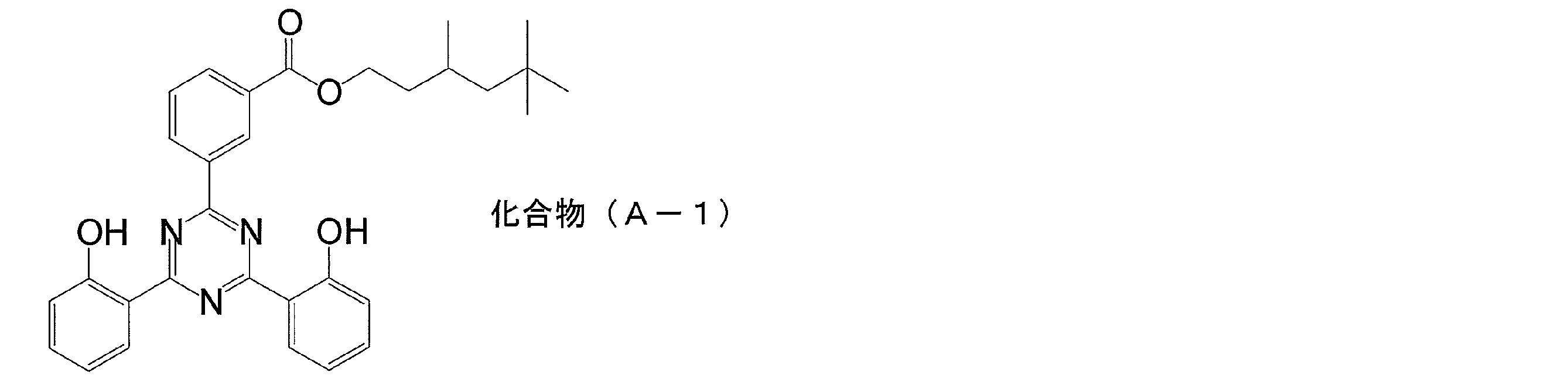
- Example 14 Example 14 was produced in the same manner as in Example 1 except that a dispersion of the following compound A-1 was used instead of the titanium dispersion. Evaluation similar to Example 1 was implemented about the obtained sample. The results are shown in Table 1. However, as the ultraviolet absorber, compound A-1 was used by being dispersed by the following method.
- the above oil phase liquid was added while stirring the obtained aqueous phase liquid at 500 rpm using a dissolver. After the addition, stirring was continued for another 5 minutes to obtain a uniform liquid.
- the liquid obtained here was further stirred at 20,000 rpm for 10 minutes using a dissolver to obtain an emulsion.
- the average particle size of the obtained emulsion 1 was measured by a laser analysis / scattering particle size distribution measuring apparatus LA950 (manufactured by Horiba, Ltd.), and the median size was 120 nm.
- the organic solvent was distilled off from the emulsion 1 using an evaporator to obtain a dispersion 1.
- the amount of the remaining organic solvent was measured by gas chromatography and found to be 0.7% by mass or less.
- the concentration of compound A-1 was 13% by mass.
- the average particle size of the dispersion was measured by the same method as described above, the median size was 121 nm.
- Example 15 to 18 and Comparative Examples 5 and 6 were produced in the same manner as in Example 1 except that Support-2 was used and the optical density was changed as shown in Table 1. Evaluation similar to Example 1 was implemented about the obtained sample. The results are shown in Table 1.
- Example 19 and Comparative Examples 7 and 8 Example 19 and Examples 7 and 8 were produced in the same manner as in Example 1 except that Support-2 was used and the binder of the overcoat layer was changed as shown in Table 1. Evaluation similar to Example 1 was implemented about the obtained sample. The results are shown in Table 1.
- Example 20 to 23 Examples 20 to 23 were produced in the same manner as in Example 1 except that Support-2 was used and the surface treatment of the support was changed as shown in Table 1. Evaluation similar to Example 1 was implemented about the obtained sample. The results are shown in Table 1.
- Examples 24-27 and Comparative Examples 9, 10 Example 24 to 27 and Examples 9 and 10 were produced in the same manner as in Example 1 except that Support-3 was used and the optical density was changed as shown in Table 1. Evaluation similar to Example 1 was implemented about the obtained sample. The results are shown in Table 1.
- Example 28 and Comparative Examples 11 and 12 Example 28 and Examples 11 and 12 were produced except that Support-3 was used and the binder of the overcoat layer was changed as shown in Table 1. Evaluation similar to Example 1 was implemented about the obtained sample. The results are shown in Table 1.
- Example 29 to 32 Examples 29 to 32 were produced in the same manner as in Example 1 except that Support-3 was used and the surface treatment of the support was changed as shown in Table 1. Evaluation similar to Example 1 was implemented about the obtained sample. The results are shown in Table 1.
- Examples 1 to 32 high weather resistance and light resistance are obtained.
- the laminated films obtained in Examples 1 to 32 have excellent interlayer adhesion and good surface shape.
- the polyolefin used for a support body is any of polyethylene and a polypropylene, it turns out that a preferable effect can be exhibited.
- Comparative Examples 1, 2, 5, 6, 9, and 10 the optical density of the polymer layer is less than 2.0, and sufficient light resistance is not obtained.
- Comparative Examples 3, 4, 7, 8, 11, and 12 since the binder of the overcoat layer is not a silicone resin or a fluorine resin, the weather resistance is low.
- Example 33 to 64 The following easy-adhesion layer was provided on the surface opposite to the surface on which the polymer layer and the overcoat layer of the laminated film obtained in Examples 1 to 32 were provided, to produce a solar cell backsheet.
- Example 65 to 96 Creation of solar cell module- 3 mm thick tempered glass, EVA sheet (SC50B manufactured by Mitsui Chemicals Fabro), crystalline solar cell, EVA sheet (SC50B manufactured by Mitsui Chemicals Fabro), and solar cells of Examples 33 to 64
- the back sheet was superposed in this order, and was hot-pressed using a vacuum laminator [Nisshinbo Co., Ltd., vacuum laminating machine], and adhered to EVA.
- the back sheet was disposed such that the easily adhesive layer was in contact with the EVA sheet.
- the adhesion conditions of EVA are as follows. Using a vacuum laminator, evacuation was performed at 128 ° C.
- the laminated films of this invention are suitable for the solar cell module backsheet used in severe environments, such as the outdoors, and its industrial applicability is high.
Landscapes
- Laminated Bodies (AREA)
- Photovoltaic Devices (AREA)
Abstract
Description
耐光性を改善するためには、最外層に紫外線吸収層を設けることが考えられる。例えば、特許文献2には、ポリエステルフィルムの支持体の上に紫外線透過率が5%以下のアクリル樹脂層を設ける技術が開示されている。
このため、着色した積層フィルムを太陽電池モジュールのバックシートとして用いることによって、バックシートの光反射率が低減し、太陽電池モジュールの発電効率を下げてしまわないように改善が求められていた。また、着色によって、太陽電池モジュール全体の意匠性を悪化させてしまわないように、更なる改善が求められていた。
さらに、強度低下した積層フィルムにおいては、積層フィルムを構成する層間で剥離が生じることがあり、太陽電池モジュール用バックシートとしての機能を十分に発揮できなくなるため、この点に関しても改善が求められていた。
具体的に、本発明は、以下の構成を有する。
[2]上記ポリマー層は、バインダー樹脂としてアクリル系樹脂、ポリエステル系樹脂、ポリウレタン系樹脂、ポリオレフィン系樹脂、シリコーン系樹脂の少なくとも1つを含むことを特徴とする[1]に記載の積層フィルム。
[3]上記ポリマー層は、紫外線吸収剤を含み、上記紫外線吸収剤の含有率は、上記バインダー樹脂の全質量に対して、50~300質量%であることを特徴とする[1]又は[2]に記載の積層フィルム。
[4]上記ポリマー層の350nmにおける光学濃度は、2.5以上であることを特徴とする[1]~[3]のいずれかに記載の積層フィルム。
[5]上記ポリマー層の平均膜厚は、0.3~18μmであることを特徴とする[1]~[4]のいずれかに記載の積層フィルム。
[6]上記ポリマー層は、塗布により形成されることを特徴とする[1]~[5]のいずれかに記載の積層フィルム。
[7]上記支持体の少なくとも一方の表面には、表面処理が施されていることを特徴とする[1]~[6]のいずれかに記載の積層フィルム。
[8]紫外線照射前の積層フィルムの黄色度を(YI‐1)とし、照度900W/m2で48時間紫外光を照射した後の積層フィルムの黄色度(YI‐2)とし、(YI‐2)―(YI‐1)で表される黄色変度をΔYIとしたときに、ΔYIは10以下であることを特徴とする[1]~[7]のいずれかに記載の積層フィルム。
[9][1]~[8]のいずれかに記載の積層フィルムを用いた太陽電池用バックシート。
[10][9]に記載の太陽電池量バックシートを用いた太陽電池用モジュール。
本発明は、支持体と、ポリマー層と、オーバーコート層を有する積層フィルムに関する。ポリマー層は、支持体の少なくとも一方の面に積層され、オーバーコート層は、ポリマー層を介して支持体とは反対側に積層される。本発明では、支持体、ポリマー層、オーバーコート層の各層間に他の層を設けることとしてもよいが、支持体、ポリマー層、オーバーコート層はこの順に隣接して積層されることが好ましい。
ここで、主成分とは、支持体を構成するポリマーのうち、50質量%を超えて含まれる成分のことをいう。本発明では、支持体を構成するポリマーのうち50質量%以上がポリオレフィンであればよく、70質量%以上がポリオレフィンであることが好ましく、90質量%以上がポリオレフィンであることがより好ましく、100質量%がポリオレフィンであることがさらに好ましい。
(2-1.ポリオレフィン)
本発明の積層フィルムを構成する支持体は、ポリオレフィンを主成分として含む。本発明で用いられるポリオレフィンとしては、例えば、ポリプロピレンやポリエチレン、ポリノルボルネン、ポリメチルペンテルやこれらを含む共重合体などが挙げられる。その中でも、ポリプロピレンとポリエチレンは、コスト、機械強度及び耐久性の観点から好ましく用いられる。
本発明でいうシンジオタクチックポリプロピレン(以下SPPとも言う)フィルムとは、上述のラセミペンタッド分率が70~99%であるものである。ラセミペンタッド分率は30~97%であることが好ましく、70~85%であることがより好ましい。ラセミペンタッド分率が30%以上の場合は耐熱性が良好でバックシートとして好ましく用いられる。一方、上限値は、上記樹脂を工業的に生産する際の生産性に関わる問題であり、ラセミペンタッド分率が高すぎることによるフィルム特性や本発明のシート特性等の問題は生じないが、現状の触媒技術では99%を超えて高めようとすると重合特性を大きく損なうという問題があり、このましくは97%程度に留めておくことが重合特性を損なわないという観点から好ましい。
なお、本発明で用いるポリプロピレンとしては、アイソタクチックポリプロピレンでもシンジオタクチックポリプロピレンが好ましく用いられる。
また、ポリエチレンの中には分子量が1000000~1500000以上の超高分子量ポリエチレンがあるが、これも本発明により好ましく用いることができる。
本発明のポリオレフィン支持体の厚みは、120~350μmであることが好ましく、160~320μmであることがより好ましく、200~280μmであることが特に好ましい。厚みは、120μm以上であると力学強度が良好であり、350μm以下であるとコスト的に有利である。
支持体の表面には、後で述べるポリマー層を塗布する前に表面処理を施すことが好ましい。表面処理としては、コロナ処理、紫外線処理(UV処理)、火炎処理、低圧プラズマ処理、大気圧プラズマ処理、サンドブラスト処理、クロム混酸処理などがある。また火炎処理としては、特許第3893394号公報、特開2007-39508号公報に記載されているシラン化合物を添加しながら行う方法も用いることができる。これらの中では簡便性や環境負荷の観点からコロナ処理、火炎処理、大気圧プラズマ処理、紫外線処理(UV処理)が好ましい。
通常、ポリオレフィンを含む支持体はポリエステルを含む支持体と比較して、ポリマー層との密着性が悪くなる傾向にある。特に、紫外線吸収剤を高濃度に含むポリマー層を積層する場合、ポリオレフィンを含む支持体との密着性が悪くなり、これらの層間で剥離が生じる場合がある。しかし、本発明では、ポリオレフィンを含む支持体の少なくとも一方の表面に、このような表面処理を施すことで、支持体とポリマー層の密着性を高めることができる。また、ポリマー層を塗布する際のハジキを防止し、湿熱環境下に曝された場合であっても、良好な接着性を示すことができる。
(3-1.光学濃度)
本発明の積層フィルムを構成するポリマー層(耐光性付与層)の、350nmにおける光学濃度は、2.0以上である。350nmにおける光学濃度は、2.0以上であればよく、2.5以上であることが好ましく、3.0以上であることがより好ましい。なお、光学濃度の上限には特に制限はないが、4.0以上になるとポリマー層中の紫外線吸収剤量が増えるため、面状や接着性が低下する場合がある。
このように、ポリマー層の光学濃度を高めることにより、ポリマー層は耐光性付与層として機能し得る。これにより、積層フィルム全体の耐光性を高めることができる。優れた耐光性を有する積層フィルムは、長期間屋外で使用しても着色や強度低下という欠陥を生じさせないため、太陽電池モジュール用バックシートとして好ましく用いられる。
まず、積層フィルム全体の試料(ポリマー層とオーバーコート層の付いた試料)について、下記式で求めた光学濃度を算出し、これを光学濃度1とする。次いで、積層フィルムから、ポリマー層とオーバーコート層を剥離した試料について下記式で求めた光学濃度を算出し、これを光学濃度2とする。
光学濃度=Log{(オーバーコート層側から積層フィルムに入射する350nmの光の強度)/(オーバーコート層の反対側に透過する350nmの光の強度)}
上記のように算出された、光学濃度1及び光学濃度2からポリマー層の光学濃度を以下の式により算出する。
ポリマー層の光学濃度=光学濃度1-光学濃度2
本発明のポリマー層は、バインダー樹脂としてアクリル系樹脂、ポリエステル系樹脂、ポリウレタン系樹脂、ポリオレフィン系樹脂、シリコーン系樹脂の少なくとも1つを含むことが好ましい。中でも、アクリル系樹脂、シリコーン系樹脂は好ましく用いられる。
好ましいアクリル樹脂の具体的としてメチルメタクリレート/メチルアクリレート/エチルメタクリレート/アクリル酸からなる共重合体、メチルメタクリレート/メチルアクリレート/ヒドロキシエチルメタクリレート/メタクリル酸からなる共重合体、メチルメタクリレート/スチレン/エチルメタクリレート/アクリル酸からなる共重合体、メチルメタクリレート/2エチルヘキシルアクリレート/ヒドロキシエチルメタクリレート/アクリル酸からなる共重合体、メチルメタクリレート/スチレン/2エチルヘキシルアクリレート/ヒドロキシエチルメタクリレート/アクリル酸からなる共重合体を挙げることができる。
本発明のアクリル系樹脂の平均分子量は2000~200000、より好ましくは5000~150000程度であることが好ましい。

また、一般式(1)中において、nは、1~50000であることが好ましく、1~10000であることがより好ましい。
本発明のシリコーン系樹脂中の「-(Si(R1)(R2)-O)n-」以外の部分はアクリル系ポリマー、ポリエステル系ポリマーなどで形成することができ、これが「-(Si(R1)(R2)-O)n-」の部分に共有結合している。「-(Si(R1)(R2)-O)n-」以外の部分は、ポリマーの中ではアクリル系ポリマーであることが好ましい。アクリル系ポリマーの組成や分子量は上述したアクリル系樹脂のところで述べたものを用いることができる。
好ましいシリコーン樹脂の例としてジメチルジメトキシシラン/γ-メタクリロキシトリメトキシシランの加水分解縮合物とメチルメタクリレート/エチルアクリレート/アクリル酸からなる共重合体、ジメチルジメトキシシラン/ジフェニルジメトキシシラン/γ-メタクリロキシトリメトキシシランの加水分解縮合物とメチルメタクリレート/エチルアクリレート/アクリル酸からなる共重合体、ジメチルジメトキシシラン/γ-メタクリロキシトリメトキシシランの加水分解縮合物とメチルメタクリレート/エチルアクリレート/メタクリル酸からなる共重合体、ジメチルジメトキシシラン/ジフェニルジメトキシシラン/γ-メタクリロキシトリメトキシシランの加水分解縮合物とメチルメタクリレート/エチルアクリレート/スチレン/メタクリル酸からなる共重合体を挙げることができる。
本発明で用いることができる紫外線吸収剤としては、有機系、無機系の紫外線吸収剤を挙げることができる。
ベンゾフェノン系の紫外線吸収剤として、2,4-ジヒドロキシベンゾフェノン、2-ヒドロキシ-4-メトキシベンゾフェノン、2-ヒドロキシ-4-メトキシ-5-スルホベンゾフェノン、2,2’,4,4’-テトラヒドロキシベンゾフェノン、ビス(2-メトキシ-4-ヒドロキシ-5-ベンゾイルフェニル)メタン等が挙げられる。
ベンゾトリアゾール系の紫外線吸収剤として、2-(2’-ヒドロキシ-5’-メチルフェニル)ベンゾトリアゾール、2-(2’-ヒドロキシ-5’-メチルフェニル)ベンゾトリアゾール、2,2’-メチレンビス[4-(1,1,3,3-テトラメチルブチル)-6-(2Hベンゾトリアゾール-2-イル)フェノール]等が挙げられる。
シアノアクリレート系の紫外線吸収剤として、エチル-2-シアノ-3,3’-ジフェニルアクリレート)等が挙げられる。
トリアジン系の紫外線吸収剤として、2-(4,6-ジフェニル-1,3,5-トリアジン-2-イル)-5-[(ヘキシル)オキシ]-フェノール等が挙げられる。
v ヒンダードアミン系の紫外線安定剤として、ビス(2,2,6,6-テトラメチル-4-ピペリジル)セバケート、コハク酸ジメチル・1-(2-ヒドロキシエチル)-4-ヒドロキシ-2,2,6,6-テトラメチルピペリジン重縮合物等が挙げられる。
そのほか、ニッケルビス(オクチルフェニル)サルファイド、及び2,4-ジ・t-ブチルフェニル-3’,5’-ジ・t-ブチル-4’-ヒドロキシベンゾエートなどを挙げることができる。
これらの紫外線吸収剤のうち、繰り返し紫外線吸収に対する耐性が高いという点で、トリアジン系紫外線吸収剤が好ましく用いられる。
ポリマー層には他の成分が含まれてもよく、他の成分としては、架橋剤、界面活性剤、フィラー等が挙げられる。
架橋剤の添加量は、ポリマー層を構成するバインダーに対して0.5~30質量%が好ましく、より好ましくは3~15質量%である。架橋剤の添加量は、0.5質量%以上であると、ポリマー層の強度及び接着性を保持しながら充分な架橋効果が得られ、30質量%以下であると、塗布液のポットライフを長く保つことができる。
フィラーの添加率は、ポリマー層のバインダーに対し20質量%以下が好ましく、より好ましくは15質量%以下である。フィラーの添加率を20質量%以下とすることにより、ポリマー層の面状をより良好に保つことができる。
本発明のポリマー層の厚みは、通常は0.3~18μmが好ましく、0.8~10μmの範囲がより好ましく、1.0~8μmの範囲がさらに好ましい。ポリマー層の厚みを0.3μm以上とすることで、湿熱環境下に曝されたときにポリマー層表面から内部に水分が浸透し難くできる。これにより、支持体との界面に水分が到達し難くなり、接着性を顕著に改善することができる。また、ポリマー層の厚みが18μm以下であるとポリマー層自体の塗布乾燥時の内部応力を小さく保つことができて良好な接着性が得られる。
(4-1.オーバーコート層のバインダー)
本発明の積層フィルムを構成するオーバーコート層は、シリコーン系樹脂及びフッ素系樹脂の少なくとも一方を含む。シリコーン系樹脂についてはポリマー層のバインダーのところで述べたものを使うことができる。
これらのポリマーは単独のモノマーを重合したホモポリマーでも良いし、2種類以上のフッ素系ポリマーを共重合したものでもよい。この例として、テトラフルオロエチレンとテトラフルオロプロピレンを共重合したコポリマー(P(TFE/HFP)と略記)、テトラフルオロエチレンとフッ化ビニリデンを共重合したコポリマー(P(TFE/VDF)と略記)等を挙げることができる。
好ましいフッ素系樹脂の具体例としてクロロトリフルオロエチレン/パーフロロエチルビニルエーテル共重合体、クロロトリフルオロエチレン/パーフロロエチルビニルエーテル/メタクリル酸共重合体、クロロトリフルオロエチレン/エチルビニルエーテル共重合体、クロロトリフルオロエチレン/エチルビニルエーテル/メタクリル酸共重合体、フッ化ビニリデン/メチルメタクリレート/メタクリル酸共重合体、フッ化ビニル/エチルアクリレート/アクリル酸共重合体が好ましく、この中でクロロトリフルオロエチレン/パーフロロエチルビニルエーテル/メタクリル酸共重合体、クロロトリフルオロエチレン/エチルビニルエーテル共重合体は特を挙げることができる。
これらのフッ素系樹脂はとしてはフッ素系樹脂を有機溶剤に溶解して用いるものでも、フッ素系樹脂の微粒子を水に分散して用いるラテックス形態のものでもよい。
オーバーコート層には他の成分が含まれてもよく、他の成分としては、架橋剤、界面活性剤、フィラー等が挙げられる。
本発明のオーバーコート層の厚みは、通常は0.5~10μmが好ましく、0.8~8μmの範囲が更に好ましく、1.0~5μmの範囲が特に好ましい。オーバーコート層の厚みが0.5μm以上であることで、湿熱環境下に曝されたときにポリマー層の劣化を抑制することができる。またオーバーコート層の厚みが10μm以下であるとオーバーコート層自体の塗布乾燥時の内部応力を小さく保つことができて良好な接着性が得られる。
本発明の積層フィルムの製造方法は、支持体の少なくとも一方の面にポリマー層を形成する工程と、ポリマー層を介して支持体とは反対側にオーバーコート層を形成する工程を有する。なお、支持体の上にポリマー層を形成する工程の前には、支持体の表面であって、ポリマー層を形成する側の表面に、表面処理を施す工程が設けられることが好ましい。
本発明のポリマー層は塗布や貼合などの公知の方法で形成することができる。中でも、塗布により、支持体上にポリマー層を形成することが好ましい。
塗布方法としては、例えば、グラビアコーター、バーコーターなどの公知の塗布方法を利用することができる。
塗布液は、塗布溶媒として水を用いた水系でもよいし、トルエンやメチルエチルケトン等の有機溶媒を用いた溶剤系でもよい。中でも、環境負荷の観点から、水を溶媒とすることが好ましい。塗布溶媒は、1種類を単独で用いてもよいし、水に水混和性有機溶剤を混合して用いてもよい。好ましい塗布溶媒の例として、水、水/エチルアルコール=95/5(質量比)、水/メチルセルソルブ=97/3(質量比)等がある。
本発明のオーバーコート層は塗布や貼合などの公知の方法で形成することができる。
塗布方法としては、例えば、グラビアコーター、バーコーターなどの公知の塗布方法を利用することができる。中でも、塗布により、ポリマー層上にオーバーコート層を形成することが好ましい。塗布方法や塗布液については、上述したものを用いることができる。
支持体の上にポリマー層を形成する工程の前には、表面処理を施す工程が設けられることが好ましい
表面処理としては、コロナ処理、紫外線処理(UV処理)、火炎処理、低圧プラズマ処理、大気圧プラズマ処理、サンドブラスト処理、クロム混酸処理などがある。また火炎処理としては、特許第3893394号公報、特開2007-39508号公報に記載されているシラン化合物を添加しながら行う方法も用いることができる。これらの中では簡便性や環境負荷の観点からコロナ処理、火炎処理、大気圧プラズマ処理、紫外線処理(UV処理)が好ましい。
本発明の積層フィルムは、太陽電池モジュール用バックシートとして好ましく用いることができる。
本発明の積層フィルムを太陽電池用バックシートとして用いる場合には積層フィルムのままの形態で用いることも可能であるし、本発明の積層フィルムのポリマー層が設けられている面の反対面にさらに他の層を積層して用いてもよい。
他の層としては封止材に対する易接着層、光反射層、バリア層などがある。これらの層は塗布、貼合などの公知の方法で設けることができる。
本発明の太陽電池モジュールは、既述の本発明の積層フィルムを用いた太陽電池用バックシートを具備した形態をとっている。具体的にはフロントシート(ガラスの場合も含む)/封止材/太陽電池セル/封止材/バックシートがこの順に積層されて封止された構造を持っている。なお、本発明のオーバーコート層はモジュールの最外層となっている。本発明の太陽電池モジュールは、既述した本発明の太陽電池用バックシートを備えることにより、優れた耐候性能と耐光性能を示し、長期に亘り安定した発電性能を発揮する。
下記のように、支持体、ポリマー層及びオーバーコート層を積層し、太陽電池モジュール用の積層シートを作製した。
<支持体-1>
-ポリエチレン支持体-
ポリエチレン支持体として厚さ200μmのポリエチレンシート(厚手ポリエチレンシート0.2mm、村上産業株式会社製)を使用した(以下、PE支持体とも言う場合がある)。
-アイソタクチックポリプロピレン支持体-
ポリプロピレン支持体として厚さ200μmのポリプロピレンシート(PPクラフトフィルム、PF-11、アクアサンデー株式会社製)を使用した(以下、PP支持体とも言う場合がある)。
-シンジオタクチックポリプロピレン支持体の作成-
以下の方法でシンジオタクチックポリプロピレン支持体を作製した。
特開平2ー274763号公報に従い、ジフェニルメチレン(シクロペンタジエニル)フルオレニルジルコニウムジクロライドおよびメチルアルミノキサンからなる触媒を用いて、水素の存在下でプロピレンの塊状重合法によってシンジオタクチックポリプロピレン{(135℃のテトラリン溶液中で測定した極限粘度が1.39dl/g、メルトフローインデックスが3.2g/10min、示差走査熱量分析で測定した結晶化温度のピーク温度が74.8℃、13C-NMRによって測定されたシンジオタクチックペンタッド分率が76.7%)(H-SPP)}を得た。上記にて得られたシンジオタクチックポリプロピレン80質量部、及びアイソタクチックホモポリプロピレン(三井東圧化学株式会社製、JHH-G:MFI 8g/10min)20質量部をブレンドし、40φmm下向きT-ダイ付き押出機により押出機温度210℃、冷却ロール温度30℃で製膜して、厚さが250μmのシンジオタクチックポリプロピレン支持体(以下、S-PP支持体とも言う場合がある)シートを得た。
表面処理は下記のいずれかの方法を用いて、支持体の片面に対して行った。各表面処理の条件は以下の通りである。
装置:ピラー社製ソリッドステートコロナ処理機6KVAモデル
電極と誘電体ロ-ルギャップクリアランス:1.6mm
処理周波数:9.6kHz
処理速度:8m/分
処理強度:0.75kV・A・分/m2
光源:低圧水銀灯
距離:20cm
雰囲気:大気圧下
処理時間:30秒
バーナー:スリット状のノズルを持つ箱型バーナー
バックロール:直径が300mmのセラミック製のバックロール
火炎処理用ガス:プロパンガス プロパンガス/空気=1/17(体積比)
ギャップ:支持体が炎の内炎の頂上から10mmの所を通過するようにセット
処理速度:50m/min
圧力:1.5Torr
雰囲気ガス:空気
放電周波数:13.56MHz
処理強度:500W・min/m2
圧力:750Torr
雰囲気ガス:アルゴン
放電周波数:5KHz
処理強度:500W・min/m2
-二酸化チタン分散物の調製-
下記組成中の各成分を混合し、その混合物をダイノミル型分散機により1時間、分散処理を施した。二酸化チタン分散物の組成は下記の通りである。
・二酸化チタン(体積平均粒子径=0.28μm) ・・・40質量部
(タイペークCR95、石原産業(株)製、固形分100質量%)
・ポリビニルアルコール水溶液(10質量%) ・・・20.0質量部
(PVA-105、(株)クラレ製)
・界面活性剤(デモールEP、花王(株)製、固形分:25質量%)
・・・0.5質量部
・蒸留水 ・・・39.5質量部
下記組成中の各成分を混合し、ポリマー層形成用塗布液を調製した。
・蒸留水 ・・・408.8質量部
・ボンロンXPS-002(39質量%)・・・ 363.7質量部
(三井化学株式会社製 アクリルバインダー(PA-1))
・上記チタン分散液 ・・・494.0質量部
・エポクロスWS-700 (25質量%) ・・・112.0質量部
(日本触媒株式会社製 オキサゾリン系架橋剤)
・リン酸水素二アンモニウム(35質量%) ・・・12.0質量部
・フッ素系界面活性剤(1質量%) ・・・18.2質量部
(ナトリウム=(3、3、4、4、5、5、6、6ノナフロロ)=2-スルホナイトオキシスクナート)
上述したようにコロナ処理を施した支持体-1(PE支持体)の一方の面にポリマー層形成用塗布液を、バインダー塗布量が5.2g/m2になるように塗布し、180℃で1分間乾燥させて、乾燥厚みが約7.0μmのポリマー層を形成した。
-オーバーコート層形成用塗布液の調製-
下記組成中の各成分を混合し、オーバーコート層形成用塗布液を調製した。オーバーコート層形成用塗布液の組成は下記の通りである。
・蒸留水 ・・・498.0質量部
・フッ素系界面活性剤(5質量%) ・・・7.2質量部
(ナトリウム=(3、3、4、4、5、5、6、6ノナフロロ)=2-スルホナイトオキシスクナート)
・スノーテックス UP(2質量%) ・・・23.5質量部
(日産化学株式会社製 コロイダルシリカ)
・TSL8340(2質量%) ・・・23.5質量部
(モメンティブ・パーフォーマンス・マテリアルズ株式会社製アミノ系シランカップリング剤)
・ケミパールW950(5質量%) ・・・124.5質量部
(三井化学株式会社製 ポリオレフィン系すべり剤)
・セラネートWSA-1070(39質量%) ・・・207.0質量部
(DIC株式会社製 シリコーン系バインダー(PS-1))
・リン酸水素二アンモニウム(35質量%) ・・・6.4質量部
・エポクロスWS-700 (25質量%) ・・・59.8質量部
(日本触媒株式会社製 オキサゾリン系架橋剤)
・エタノール ・・・50.0質量部
得られたオーバーコート層形成用塗布液を支持体-1のポリマー層の上に、バインダー塗布量が2.0g/m2になるように塗布し、180℃で1分間乾燥させて、乾燥厚み約2μmのオーバーコート層を形成した。
このようにして、PE支持体、ポリマー層およびオーバーコート層がこの順に積層された実施例1の太陽電池モジュール用積層シートを作製した。
<光学濃度>
島津製作所株式会社製分光光度計UV-3100を用いて積層フィルムの350nmにおける光線透過率T1と、ポリマー層とオーバーコート層を除去した試料の350nmにおける光線透過率T2を測定して下記の式を用いて光学濃度ODを計算した。
OD=Log(100/T1)-Log(100/T2)
ただし、Logは10を底とする対数を表し、T1とT2はパーセントで表す。なお、ポリマー層とオーバーコート層の除去は、有機溶剤を用いて膜を溶解することにより行った。
試料の面状を目視により観察し、下記の評価基準に従って評価した。このうち、ランク4及び5が実用上許容可能な範囲である。
5:ムラやハジキが全くみられなかった。
4:ムラが極わずかにみられたが、ハジキは確認できなかった。
3:ムラがややみられたが、ハジキは確認できなかった。
2:ムラがはっきり確認され、一部に(10個/m2未満)ハジキがみられた。
1:ムラがはっきり確認され、ハジキが10個/m2以上みられた。
日本電色工業(株)製の分光式色差計「Spectro Color Meter SE2000」を用いて、各バックシート試料のYI値(YI-1)を測定した。その後、各バックシート試料に対し、岩崎電気(株)製の耐光性試験機「アイスーパーUVテスター W-151」を用い、照度900W/m2で48時間、紫外光を照射した。但し、紫外光照射時における環境条件は、63℃、相対湿度50%とした。
次いで、上記同様の分光式色差計(Spectro Color Meter SE2000、日本電色工業(株)製)を用い、再び各バックシート試料のYI値(YI-2)を測定した。
5:YI値が3未満であった。
4:YI値が3以上5未満であった。
3:YI値が5以上10未満であった。
2:YI値が10以上20未満であった。
1:YI値が20以上であった。
(1)湿熱経時前の接着性
試料の塗布層表面に片刃のカミソリで縦横それぞれ6本ずつの傷をつけ、25マスのマス目を形成した。この上にマイラーテープ(ポリエステルテープ)を貼り付け、手動で試料表面に沿って180°方向に引っ張って剥離した。このとき、剥離されたマス目の数によって、バック層の接着力を下記の評価基準にしたがってランク分けした。評価ランク4、5が、実用上許容可能な範囲である。
5:剥離したマス目はなかった(0マス)。
4:剥離したマス目が0マスから0.5マス未満であった。
3:剥離したマス目が0.5マス以上2マス未満であった。
2:剥離したマス目が2マス以上10マス未満であった。
1:剥離したマス目が10マス以上であった。
試料を120℃、相対湿度100%の環境条件下で48時間保持した後、25℃、相対湿度60%の環境下において1時間調湿した後、上記接着性の評価と同様の方法で接着性を評価した。
ポリマー層の二酸化チタンの添加量を変えることにより、光学濃度を表1のように変更する以外は実施例1と同様にして実施例2~4及び実施例1、2を作製した。得られた試料について実施例1と同様の評価を実施した。結果を表1に示す。
オーバーコート層のバインダーを表1のように変更する以外は実施例1と同様にして実施例5及び実施例3、4を作製した。得られた試料について実施例1と同様の評価を実施した。結果を表1に示す。
支持体の表面処理を表1のように変更する以外は実施例1と同様にして実施例6~9を実施した。得られた試料について実施例1と同様の評価を実施した。結果を表1に示す。
ポリマー層のバインダーを表1のように変更する以外は実施例1と同様にして実施例10~13を作製した。得られた試料について実施例1と同様の評価を実施した。結果を表1に示す。
チタン分散液の代わりに下記化合物A-1の分散液を使用する以外は実施例1と同様にして実施例14を作製した。得られた試料について実施例1と同様の評価を実施した。結果を表1に示す。ただし、紫外線吸収剤としては化合物A-1を下記の方法で分散して用いた。
-化合物(A-1)の分散物の調製-
酢酸エチル35.4質量部とテトラヒドロフラン8.8質量部とを混合した混合溶媒に、下記化合物(A-1)18.94質量部を添加し、50℃に加熱して10分間攪拌し、化合物(A-1)が溶解した油相液を調製した。
支持体-2を用いることと、光学濃度を表1のように変更する以外は実施例1と同様にして実施例15~18及び実施例5、6を作製した。得られた試料について実施例1と同様の評価を実施した。結果を表1に示す。
支持体-2を用いることと、オーバーコート層のバインダーを表1のように変更する以外は実施例1と同様にして実施例19及び実施例7、8を作製した。得られた試料について実施例1と同様の評価を実施した。結果を表1に示す。
支持体-2を用いることと支持体の表面処理を表1のように変更する以外は実施例1と同様にして実施例20~23を作製した。得られた試料について実施例1と同様の評価を実施した。結果を表1に示す。
支持体-3を用いることと、光学濃度を表1のように変更する以外は実施例1と同様にして実施例24~27及び実施例9、10を作製した。得られた試料について実施例1と同様の評価を実施した。結果を表1に示す。
支持体-3を用いることと、オーバーコート層のバインダーを表1のように変更する以外は実施例28及び実施例11、12を作製した。得られた試料について実施例1と同様の評価を実施した。結果を表1に示す。
支持体-3を用いることと支持体の表面処理を表1のように変更する以外は実施例1と同様にして実施例29~32を作製した。得られた試料について実施例1と同様の評価を実施した。結果を表1に示す。
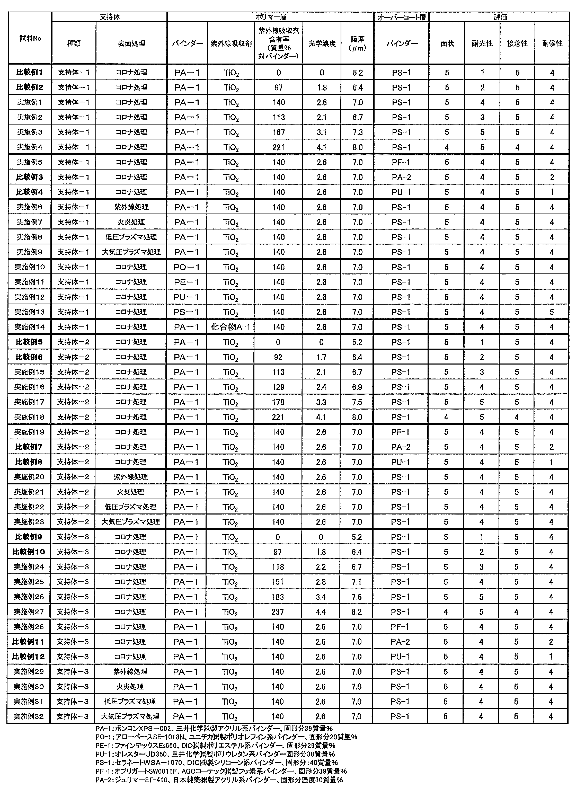
一方、比較例1、2、5、6、9及び10では、ポリマー層の光学濃度が2.0未満であり、十分な耐光性が得られていない。また、比較例3、4、7、8、11、12では、オーバーコート層のバインダーがシリコーン系樹脂またはフッ素系樹脂ではないため、耐候性が低い。
実施例1~32で得られた積層フィルムのポリマー層とオーバーコート層が設けられている面の反対面に下記の易接着層を設けて太陽電池用バックシートを作製した。
下記組成中の各成分を混合し、易接着層形成用塗布液を調製した。
(易接着層形成用塗布液の組成)
上記チタン分散液 ・・・300質量部
蒸留水 ・・・40質量部
エポクロスWS700(25質量%) ・・・100質量部
(日本触媒株式会社製 オキサゾリン系架橋剤)
アローベースSE-1013N(20質量%) ・・・550質量部
(ユニチカ株式会社製 ポリオレフイン系バインダー(PO-1))
フッ素系界面活性剤(1質量%) vvv ・・・10質量部
(ナトリウム=(3、3、4、4、5、5、6、6ノナフロロ)=2-スルホナイトオキシスクナート)
実施例1~32の積層フィルムのポリマー層とオーバーコート層が設けられている面の反対面に上記コロナ処理を施した。その後この面にポリマー層とオーバーコート層が設けられている面の反対面に易接着層形成用塗布液を、バインダー塗布量が3.0g/m2になるように塗布し、180℃で1分間乾燥させて、乾燥厚みが約4.5μmの易接着層を形成した。
-太陽電池モジュールの作成-
厚さ3mmの強化ガラスと、EVAシート〔三井化学ファブロ社製のSC50B〕と、結晶系太陽電池セルと、EVAシート〔三井化学ファブロ社製のSC50B〕と、実施例33~64の太陽電池用バックシートとをこの順に重ね合わせ、真空ラミネータ〔日清紡社製、真空ラミネート機〕を用いてホットプレスすることにより、EVAと接着させた。ただし、バックシートはその易接着性層がEVAシートと接触するように配置した。また、EVAの接着条件は、以下の通りである。
真空ラミネータを用いて、128℃で3分間の真空引き後、2分間加圧して仮接着した。その後、ドライオーブンにて150℃で30分間、本接着処理を施した。
作製した太陽電池モジュール1~30について、発電運転をしたところ、いずれも太陽電池として良好な発電性能を示した。
4 ポリマー層
6 オーバーコート層
10 積層フィルム
Claims (10)
- 支持体と、前記支持体の少なくとも一方の面に積層されるポリマー層と、前記ポリマー層を介して前記支持体とは反対側に積層されるオーバーコート層とを有し、
前記支持体は、ポリオレフィンを主成分として含み、
前記ポリマー層の350nmにおける光学濃度は、2.0以上であり、
前記オーバーコート層は、シリコーン系樹脂及びフッ素系樹脂の少なくとも一方を含むことを特徴とする積層フィルム。 - 前記ポリマー層は、バインダー樹脂としてアクリル系樹脂、ポリエステル系樹脂、ポリウレタン系樹脂、ポリオレフィン系樹脂、シリコーン系樹脂の少なくとも1つを含むことを特徴とする請求項1に記載の積層フィルム。
- 前記ポリマー層は、紫外線吸収剤を含み、前記紫外線吸収剤の含有率は、前記バインダー樹脂の全質量に対して、50~300質量%であることを特徴とする請求項1又は2に記載の積層フィルム。
- 前記ポリマー層の350nmにおける光学濃度は、2.5以上であることを特徴とする請求項1~3のいずれか1項に記載の積層フィルム。
- 前記ポリマー層の平均膜厚は、0.3~18μmであることを特徴とする請求項1~4のいずれか1項に記載の積層フィルム。
- 前記ポリマー層は、塗布により形成されることを特徴とする請求項1~5のいずれか1項に記載の積層フィルム。
- 前記支持体の少なくとも一方の表面には、表面処理が施されていることを特徴とする請求項1~6のいずれか1項に記載の積層フィルム。
- 紫外線照射前の積層フィルムの黄色度をYI-1とし、照度900W/m2で48時間紫外光を照射した後の積層フィルムの黄色度YI-2とし、YI-2からYI-1を引いて得られる黄色変度をΔYIとしたときに、ΔYIは10以下であることを特徴とする請求項1~7のいずれか1項に記載の積層フィルム。
- 請求項1~8のいずれか1項に記載の積層フィルムを用いた太陽電池用バックシート。
- 請求項9に記載の太陽電池量バックシートを用いた太陽電池用モジュール。
Priority Applications (3)
| Application Number | Priority Date | Filing Date | Title |
|---|---|---|---|
| KR1020157024387A KR20150118996A (ko) | 2013-03-15 | 2014-03-14 | 적층 시트 및 태양 전지 모듈용 백시트 |
| CN201480014250.9A CN105189117B (zh) | 2013-03-15 | 2014-03-14 | 层叠片及太阳能电池模块用背板 |
| US14/850,533 US20150380586A1 (en) | 2013-03-15 | 2015-09-10 | Laminated sheet and back sheet for solar cell modules |
Applications Claiming Priority (2)
| Application Number | Priority Date | Filing Date | Title |
|---|---|---|---|
| JP2013053972A JP5860426B2 (ja) | 2013-03-15 | 2013-03-15 | 積層シート及び太陽電池モジュール用バックシート |
| JP2013-053972 | 2013-03-15 |
Related Child Applications (1)
| Application Number | Title | Priority Date | Filing Date |
|---|---|---|---|
| US14/850,533 Continuation US20150380586A1 (en) | 2013-03-15 | 2015-09-10 | Laminated sheet and back sheet for solar cell modules |
Publications (1)
| Publication Number | Publication Date |
|---|---|
| WO2014142297A1 true WO2014142297A1 (ja) | 2014-09-18 |
Family
ID=51536945
Family Applications (1)
| Application Number | Title | Priority Date | Filing Date |
|---|---|---|---|
| PCT/JP2014/056863 Ceased WO2014142297A1 (ja) | 2013-03-15 | 2014-03-14 | 積層シート及び太陽電池モジュール用バックシート |
Country Status (5)
| Country | Link |
|---|---|
| US (1) | US20150380586A1 (ja) |
| JP (1) | JP5860426B2 (ja) |
| KR (1) | KR20150118996A (ja) |
| CN (1) | CN105189117B (ja) |
| WO (1) | WO2014142297A1 (ja) |
Families Citing this family (5)
| Publication number | Priority date | Publication date | Assignee | Title |
|---|---|---|---|---|
| US20170044340A1 (en) * | 2014-05-27 | 2017-02-16 | Sabic Global Technologies B.V. | Self-cleansing super-hydrophobic polymeric materials for anti-soiling |
| KR101696759B1 (ko) * | 2015-12-08 | 2017-01-16 | 주식회사 에스케이씨에스 | 수분방지 특성이 우수한 백시트 및 그의 제조방법 |
| KR20200077154A (ko) | 2018-12-20 | 2020-06-30 | 롯데케미칼 주식회사 | 태양전지용 폴리올레핀계 백시트의 실리콘 부착 강도 개선 방법 |
| EP4077563A1 (en) | 2019-12-20 | 2022-10-26 | SABIC Global Technologies B.V. | Process for the preparation of a bonded structure, a bonded structure and use of said bonded structure for preparing an automotive part |
| CN111816723B (zh) * | 2020-08-21 | 2021-12-24 | 苏州赛伍应用技术股份有限公司 | 一种光伏组件用载体膜及光伏组件 |
Citations (5)
| Publication number | Priority date | Publication date | Assignee | Title |
|---|---|---|---|---|
| JP2010050329A (ja) * | 2008-08-22 | 2010-03-04 | Toray Ind Inc | 太陽電池モジュール用背面保護シート |
| JP2011146658A (ja) * | 2010-01-18 | 2011-07-28 | Fujifilm Corp | 太陽電池用バックシート及びその製造方法、並びに太陽電池モジュール |
| JP2012227382A (ja) * | 2011-04-20 | 2012-11-15 | Daicel Corp | 太陽電池バックシート |
| JP2013035277A (ja) * | 2011-07-14 | 2013-02-21 | Fujifilm Corp | ポリマーシートとその製造方法、太陽電池用バックシートおよび太陽電池モジュール |
| JP2013042007A (ja) * | 2011-08-17 | 2013-02-28 | Fujifilm Corp | 太陽電池モジュール用バックシートおよび太陽電池モジュール |
Family Cites Families (11)
| Publication number | Priority date | Publication date | Assignee | Title |
|---|---|---|---|---|
| JP2001111076A (ja) * | 1999-10-08 | 2001-04-20 | Tdk Corp | コーティング体および太陽電池モジュール |
| JP2007150084A (ja) * | 2005-11-29 | 2007-06-14 | Dainippon Printing Co Ltd | 太陽電池モジュール用裏面保護シート、太陽電池モジュール用裏面積層体、および、太陽電池モジュール |
| JPWO2007105306A1 (ja) * | 2006-03-14 | 2009-07-30 | 東レ株式会社 | 太陽電池用ポリエステル樹脂シート、それを用いてなる積層品、太陽電池裏面保護シート、およびモジュール |
| CN101934621B (zh) * | 2006-03-14 | 2013-04-24 | 东丽株式会社 | 太阳能电池用聚酯树脂片、使用该聚酯树脂片的叠层品、太阳能电池背面保护片以及组件 |
| WO2010109947A1 (ja) * | 2009-03-27 | 2010-09-30 | コニカミノルタオプト株式会社 | 防湿フィルム、その製造方法、それを用いた太陽電池モジュール用バックシート及び太陽電池モジュール |
| JP5493560B2 (ja) * | 2009-08-03 | 2014-05-14 | 凸版印刷株式会社 | 太陽電池用裏面保護シート及びこれを用いた太陽電池モジュール |
| JP2012017456A (ja) * | 2010-06-11 | 2012-01-26 | Fujifilm Corp | ポリエステルフィルム及びその製造方法、太陽電池用バックシート、並びに太陽電池モジュール |
| US20120048348A1 (en) * | 2010-08-26 | 2012-03-01 | Fujifilm Corporation | Solar cell protective sheet and its production method, backsheet for solar cell, and solar cell module |
| JP2012084819A (ja) * | 2010-09-17 | 2012-04-26 | Fujifilm Corp | 太陽電池のバックシート用基材フィルム及びその製造方法 |
| EP2639836A4 (en) * | 2010-11-12 | 2016-08-24 | Fujifilm Corp | REPLACEMENT PLATE FOR SOLAR CELLS AND MANUFACTURING METHOD THEREFOR, AND SOLAR CELL MODULE |
| WO2012063945A1 (ja) * | 2010-11-12 | 2012-05-18 | 富士フイルム株式会社 | 太陽電池用バックシート及び太陽電池モジュール |
-
2013
- 2013-03-15 JP JP2013053972A patent/JP5860426B2/ja active Active
-
2014
- 2014-03-14 CN CN201480014250.9A patent/CN105189117B/zh active Active
- 2014-03-14 KR KR1020157024387A patent/KR20150118996A/ko not_active Ceased
- 2014-03-14 WO PCT/JP2014/056863 patent/WO2014142297A1/ja not_active Ceased
-
2015
- 2015-09-10 US US14/850,533 patent/US20150380586A1/en not_active Abandoned
Patent Citations (5)
| Publication number | Priority date | Publication date | Assignee | Title |
|---|---|---|---|---|
| JP2010050329A (ja) * | 2008-08-22 | 2010-03-04 | Toray Ind Inc | 太陽電池モジュール用背面保護シート |
| JP2011146658A (ja) * | 2010-01-18 | 2011-07-28 | Fujifilm Corp | 太陽電池用バックシート及びその製造方法、並びに太陽電池モジュール |
| JP2012227382A (ja) * | 2011-04-20 | 2012-11-15 | Daicel Corp | 太陽電池バックシート |
| JP2013035277A (ja) * | 2011-07-14 | 2013-02-21 | Fujifilm Corp | ポリマーシートとその製造方法、太陽電池用バックシートおよび太陽電池モジュール |
| JP2013042007A (ja) * | 2011-08-17 | 2013-02-28 | Fujifilm Corp | 太陽電池モジュール用バックシートおよび太陽電池モジュール |
Also Published As
| Publication number | Publication date |
|---|---|
| CN105189117B (zh) | 2018-06-22 |
| JP2014177082A (ja) | 2014-09-25 |
| JP5860426B2 (ja) | 2016-02-16 |
| CN105189117A (zh) | 2015-12-23 |
| US20150380586A1 (en) | 2015-12-31 |
| KR20150118996A (ko) | 2015-10-23 |
Similar Documents
| Publication | Publication Date | Title |
|---|---|---|
| TWI472432B (zh) | 多層膜及包含其之光伏打模組 | |
| JP6011817B2 (ja) | 多層フィルム及びこれを含む光電池モジュール | |
| CN102442044B (zh) | 太阳能电池保护板及其制备方法,太阳能电池用背板和太阳能电池组件 | |
| JP5860426B2 (ja) | 積層シート及び太陽電池モジュール用バックシート | |
| TWI499060B (zh) | 多層膜及包含其之光伏打模組 | |
| CN103079816A (zh) | 具有包封剂和光伏电池的阻挡组件 | |
| CN103650160B (zh) | 太阳能电池用保护板,其制造方法,太阳能电池用背板以及太阳能电池模块 | |
| US12157941B2 (en) | Ultraviolet radiation and atomic oxygen barrier films and methods of making and using the same | |
| JP6200131B2 (ja) | ポリマーシート、太陽電池用裏面保護シートおよび太陽電池モジュール | |
| WO2012063649A1 (ja) | 太陽電池用バックシート及びその製造方法、並びに太陽電池モジュール | |
| JP5606849B2 (ja) | 太陽電池用バックシート用ポリマーシート及び太陽電池モジュール | |
| JP2016195165A (ja) | 太陽電池用透明シート、太陽電池用透明バックシート、及び太陽電池モジュール | |
| JP6271738B2 (ja) | 積層ポリエステルフィルム及びその製造方法、太陽電池用保護シート、並びに太陽電池モジュール | |
| JP5660999B2 (ja) | ポリマーシート、太陽電池モジュール用バックシートおよび太陽電池モジュール | |
| JP5727319B2 (ja) | ポリマーシート、太陽電池用保護シート及び太陽電池モジュール | |
| JP2013056543A (ja) | 太陽電池モジュール用ポリマーシート、太陽電池モジュール用バックシートおよび太陽電池モジュール | |
| WO2014192774A1 (ja) | 太陽電池用バックシート、及び太陽電池モジュール | |
| TWI466776B (zh) | 多層膜及包含其之光伏打模組 | |
| JP6050652B2 (ja) | 太陽電池用ポリマーシートおよび太陽電池モジュール | |
| JP2015037171A (ja) | 太陽電池用保護シート、太陽電池用バックシート及び太陽電池モジュール | |
| KR20120134328A (ko) | 불소계 수지 조성물, 이의 제조 방법 및 이를 포함하는 광전지 모듈 |
Legal Events
| Date | Code | Title | Description |
|---|---|---|---|
| WWE | Wipo information: entry into national phase |
Ref document number: 201480014250.9 Country of ref document: CN |
|
| 121 | Ep: the epo has been informed by wipo that ep was designated in this application |
Ref document number: 14763049 Country of ref document: EP Kind code of ref document: A1 |
|
| ENP | Entry into the national phase |
Ref document number: 20157024387 Country of ref document: KR Kind code of ref document: A |
|
| NENP | Non-entry into the national phase |
Ref country code: DE |
|
| 122 | Ep: pct application non-entry in european phase |
Ref document number: 14763049 Country of ref document: EP Kind code of ref document: A1 |