WO2014141805A1 - 作業機の制御装置 - Google Patents
作業機の制御装置 Download PDFInfo
- Publication number
- WO2014141805A1 WO2014141805A1 PCT/JP2014/053335 JP2014053335W WO2014141805A1 WO 2014141805 A1 WO2014141805 A1 WO 2014141805A1 JP 2014053335 W JP2014053335 W JP 2014053335W WO 2014141805 A1 WO2014141805 A1 WO 2014141805A1
- Authority
- WO
- WIPO (PCT)
- Prior art keywords
- control device
- machine
- work machine
- unit
- storage unit
- Prior art date
- Legal status (The legal status is an assumption and is not a legal conclusion. Google has not performed a legal analysis and makes no representation as to the accuracy of the status listed.)
- Ceased
Links
Images



Classifications
-
- E—FIXED CONSTRUCTIONS
- E02—HYDRAULIC ENGINEERING; FOUNDATIONS; SOIL SHIFTING
- E02F—DREDGING; SOIL-SHIFTING
- E02F9/00—Component parts of dredgers or soil-shifting machines, not restricted to one of the kinds covered by groups E02F3/00 - E02F7/00
- E02F9/20—Drives; Control devices
- E02F9/2058—Electric or electro-mechanical or mechanical control devices of vehicle sub-units
- E02F9/2062—Control of propulsion units
- E02F9/2075—Control of propulsion units of the hybrid type
-
- E—FIXED CONSTRUCTIONS
- E02—HYDRAULIC ENGINEERING; FOUNDATIONS; SOIL SHIFTING
- E02F—DREDGING; SOIL-SHIFTING
- E02F9/00—Component parts of dredgers or soil-shifting machines, not restricted to one of the kinds covered by groups E02F3/00 - E02F7/00
- E02F9/20—Drives; Control devices
- E02F9/22—Hydraulic or pneumatic drives
- E02F9/2278—Hydraulic circuits
- E02F9/2285—Pilot-operated systems
-
- E—FIXED CONSTRUCTIONS
- E02—HYDRAULIC ENGINEERING; FOUNDATIONS; SOIL SHIFTING
- E02F—DREDGING; SOIL-SHIFTING
- E02F9/00—Component parts of dredgers or soil-shifting machines, not restricted to one of the kinds covered by groups E02F3/00 - E02F7/00
- E02F9/20—Drives; Control devices
- E02F9/22—Hydraulic or pneumatic drives
- E02F9/2278—Hydraulic circuits
- E02F9/2292—Systems with two or more pumps
-
- E—FIXED CONSTRUCTIONS
- E02—HYDRAULIC ENGINEERING; FOUNDATIONS; SOIL SHIFTING
- E02F—DREDGING; SOIL-SHIFTING
- E02F9/00—Component parts of dredgers or soil-shifting machines, not restricted to one of the kinds covered by groups E02F3/00 - E02F7/00
- E02F9/20—Drives; Control devices
- E02F9/22—Hydraulic or pneumatic drives
- E02F9/2278—Hydraulic circuits
- E02F9/2296—Systems with a variable displacement pump
-
- F—MECHANICAL ENGINEERING; LIGHTING; HEATING; WEAPONS; BLASTING
- F04—POSITIVE - DISPLACEMENT MACHINES FOR LIQUIDS; PUMPS FOR LIQUIDS OR ELASTIC FLUIDS
- F04D—NON-POSITIVE-DISPLACEMENT PUMPS
- F04D27/00—Control, e.g. regulation, of pumps, pumping installations or pumping systems specially adapted for elastic fluids
-
- G—PHYSICS
- G05—CONTROLLING; REGULATING
- G05B—CONTROL OR REGULATING SYSTEMS IN GENERAL; FUNCTIONAL ELEMENTS OF SUCH SYSTEMS; MONITORING OR TESTING ARRANGEMENTS FOR SUCH SYSTEMS OR ELEMENTS
- G05B15/00—Systems controlled by a computer
- G05B15/02—Systems controlled by a computer electric
Definitions
- the present invention relates to a control device for a work machine operated by electronic control.
- JP2012-241339A discloses a hybrid work machine that includes a hydraulic pump driven by an engine and an electric motor that assists the driving of the hydraulic pump by the engine, and operates a hydraulic actuator by hydraulic oil discharged from the hydraulic pump. ing.
- This hybrid work machine includes a control device that controls the engine and the electric motor based on signals from various sensors.
- the present invention has been made in view of the above-described problems, and an object thereof is to facilitate the update of a program for a control device for a work machine.
- a work machine control device that controls operation of a work machine stores a constant used in a program for operating the work machine, and stores the constant in the storage unit.
- a control unit that executes a program using a constant to control the operation of the working machine, a connector unit to which an external device capable of inputting an update value for overwriting the constant stored in the storage unit is connected; Is provided.
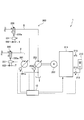
- FIG. 1 is a schematic configuration diagram of a fluid pressure control system of a hybrid construction machine to which a working machine control device according to an embodiment of the present invention is applied.
- FIG. 2 is a schematic configuration diagram of an assist regeneration mechanism connected to the fluid pressure control system.
- FIG. 3 is a block diagram of the control device for the work machine according to the embodiment of the present invention.
- FIG. 4 is a flowchart of constant update processing executed by the work machine control device according to the embodiment of the present invention.
- control device 10 a working machine control device (hereinafter simply referred to as “control device”) 10 according to an embodiment of the present invention will be described.
- the hybrid construction machine 1 includes a fluid pressure control system 100 shown in FIG. 1 and an assist regeneration mechanism 200 shown in FIG.
- the fluid pressure control system 100 is a device that controls the operation of the hybrid construction machine 1.
- the hybrid construction machine 1 is a hydraulic working machine such as a hydraulic excavator.
- the fluid pressure control system 100 controls, for example, the expansion and contraction operation of the boom cylinder 3 as an actuator that drives the boom 2 (load) of the excavation attachment of a hydraulic excavator.
- the fluid pressure control system 100 includes a boom cylinder 3, a main pump 101 that discharges hydraulic oil as a working fluid to drive the boom cylinder 3, a pilot pump 102, a main control valve 110, a main passage 103, 1 passage 121, 2nd passage 122, and control device 10 which controls operation of hybrid construction machine 1 are provided.
- the interior of the boom cylinder 3 is partitioned into a rod side pressure chamber 6 and a bottom side pressure chamber 7 by a piston 4 that slidably moves within the boom cylinder 3.
- a piston rod 5 is connected to the piston 4.
- the boom 2 is connected to the tip of the piston rod 5 located outside the boom cylinder 3.
- the main pump 101 and the pilot pump 102 are hydraulic supply sources that discharge hydraulic fluid, and are variable displacement hydraulic pumps that can adjust the discharge amount of hydraulic fluid by controlling the inclination angle of each swash plate. .
- the main pump 101 and the pilot pump 102 are driven by an engine 106 (see FIG. 3) mounted on the hybrid construction machine 1.
- the hydraulic oil discharged from the main pump 101 is supplied to the main control valve 110 through the main passage 103.
- the main pump 101 and the main control valve 110 are connected by the main passage 103.
- the hydraulic oil discharged from the assist pump 201 of the assist regeneration mechanism 200 (see FIG. 2) is guided to the main passage 103 through the sub passage 8.
- the main control valve 110 and the rod side pressure chamber 6 of the boom cylinder 3 are connected by a first passage 121, and the main control valve 110 and the bottom side pressure chamber 7 of the boom cylinder 3 are connected by a second passage 122.
- the second passage 122 is connected to a return passage 9 through which a part of the hydraulic oil discharged from the bottom pressure chamber 7 flows.
- the hydraulic oil that has flowed into the return passage 9 drives the regenerative motor 202 of the assist regenerative mechanism 200 (see FIG. 2).
- the main control valve 110 is a proportional valve that switches between supply and discharge of hydraulic oil to and from the boom cylinder 3.
- the main control valve 110 is operated by a pilot pressure that is a hydraulic pressure of hydraulic oil supplied from the pilot pump 102 to the pilot chambers 111 and 112 of the main control valve 110.
- Control of the pilot pressure supplied to the pilot chambers 111 and 112 is performed by the control device 10 controlling the pilot solenoid valve 105 based on a lever operation by an operator of the hybrid construction machine 1.
- the valve mechanism of the main control valve 110 is switched to the position a.
- the hydraulic oil discharged from the main pump 101 is supplied to the rod-side pressure chamber 6 through the first passage 121, and the hydraulic oil in the bottom-side pressure chamber 7 is discharged to the tank T through the second passage 122.
- the piston rod 5 in the boom cylinder 3 moves downward in FIG. 1, the boom cylinder 3 contracts, and the boom 2 descends.
- the valve mechanism of the main control valve 110 is switched to the position b.
- the hydraulic oil discharged from the main pump 101 is supplied to the bottom pressure chamber 7 through the second passage 122, and the hydraulic oil in the rod side pressure chamber 6 is discharged to the tank T through the first passage 121.
- the piston rod 5 in the boom cylinder 3 moves upward in FIG. 1, the boom cylinder 3 extends, and the boom 2 rises.
- the main control valve 110 is a proportional valve, it is possible to adjust the ascending speed and descending speed of the boom 2 in a stepless manner according to the amount of lever operation by the operator.
- the main control valve 110 has three switching positions: a contracted position a for contracting the boom cylinder 3, an extended position b for extending the boom cylinder 3, and a blocking position c for holding the load of the boom cylinder 3. ing.
- the assist regeneration mechanism 200 includes regeneration control that collects hydraulic energy of hydraulic oil discharged from the bottom-side pressure chamber 7 as electric energy when the boom cylinder 3 is contracted, and assist control that applies assist force when the boom cylinder 3 is extended. Execute.
- the assist regeneration mechanism 200 discharges hydraulic oil and assists the driving of the boom cylinder 3 by the main pump 101, and the regenerative drive driven by the hydraulic oil discharged from the boom cylinder 3.
- a motor 202, a motor generator 203 that can be driven by the regenerative motor 202 and that can drive the assist pump 201, a battery 210, an inverter 211, a return path 9, and a sub path 8 are provided.
- the assist pump 201 is a variable displacement hydraulic pump capable of controlling the discharge amount by controlling the inclination angle of the swash plate.
- the assist pump 201 is driven by the motor generator 203 and supplies hydraulic oil to the main passage 103 through the sub passage 8.
- the inclination angle of the swash plate of the assist pump 201 is controlled by the inclination angle controller 201a.
- the tilt angle controller 201 a is controlled by the control device 10.
- the sub passage 8 is provided with a sub control valve 220 that controls the supply of hydraulic oil to the main passage 103.
- the valve mechanism of the sub-control valve 220 provides a communication position d for supplying hydraulic oil to the main passage 103 in accordance with a pilot pressure supplied from the pilot pump 102 to the pilot chamber 220a, and supplies hydraulic oil to the main passage 103. It switches to the blocking position e where it stops.
- the control of the pilot pressure supplied to the pilot chamber 220a is performed by the control device 10 controlling the pilot electromagnetic valve 221 based on a lever operation by an operator of the hybrid construction machine 1.
- the regenerative motor 202 is a variable displacement hydraulic motor capable of controlling the output torque by controlling the inclination angle of the swash plate.
- the regenerative motor 202 is driven by hydraulic oil that has been discharged from the bottom pressure chamber 7 of the boom cylinder 3 and has flowed through the return passage 9.
- the inclination angle of the swash plate of the regenerative motor 202 is controlled by an inclination angle controller 202a.
- the tilt angle controller 202 a is controlled by the control device 10.
- the return passage 9 is provided with a return control valve 230 that controls the supply of hydraulic oil to the regenerative motor 202.
- the valve mechanism of the return control valve 230 provides a communication position f for supplying hydraulic oil to the regenerative motor 202 according to a pilot pressure supplied from the pilot pump 102 to the pilot chamber 230a, and supply of the hydraulic oil to the regenerative motor 202. It switches to the blocking position g to stop.
- the control of the pilot pressure supplied to the pilot chamber 230a is performed by the control device 10 controlling the pilot electromagnetic valve 231 based on a lever operation by an operator of the hybrid construction machine 1.
- the motor generator 203 is a rotating electrical machine having a function as an electric motor that drives the assist pump 201 based on the electric power of the battery 210 and a function as a generator that is driven by the regenerative motor 202 to generate electric power.
- the rotating shafts of the motor generator 203, the regenerative motor 202, and the assist pump 201 are arranged on the same axis.
- the rotating shaft of the motor generator 203 rotates
- the rotating shafts of the regenerative motor 202 and the assist pump 201 rotate in conjunction with each other.
- the rotation shaft of the regenerative motor 202 rotates
- the rotation shafts of the motor generator 203 and the assist pump 201 rotate together.
- the motor generator 203 is connected to a battery 210 as a power storage device via an inverter 211.
- the battery 210 is configured by connecting a plurality of secondary battery cells such as rechargeable lithium ion batteries in series.
- a relay switch 213 for controlling an electrical connection state is provided in the electrical wiring 212 that connects the battery 210 and the inverter 211.
- the relay switch 213 is ON / OFF controlled by the control device 10.
- the inverter 211 is controlled by the control device 10 and converts direct current into alternating current or alternating current into direct current.
- the direct current from the battery 210 is converted into a three-phase alternating current having an arbitrary frequency and supplied to the motor generator 203.
- the motor generator 203 is caused to function as a generator, the three-phase alternating current from the motor generator 203 is converted into direct current and supplied to the battery 210.
- control device 10 will be described with reference to FIG.
- the control device 10 stores the constants used in the program for operating the hybrid construction machine 1 and executes the program using the constants stored in the storage unit 20 to control the operation of the hybrid construction machine 1.
- the connector unit 40 to which the computer 90 as an external device capable of inputting an update value for overwriting the constant stored in the storage unit 20 is connected, and the operation status of the hybrid construction machine 1 An input unit 50 to which various signals are input, and an output unit 60 for outputting signals for controlling the engine 106, the motor generator 203, various valves, and the like.
- control device 10 is provided inside the case 11 that houses the storage unit 20, the control unit 30, the input unit 50, and the output unit 60, and updates the program stored in the control unit 30.
- Internal connector 12 the control device 10 is provided inside the case 11 that houses the storage unit 20, the control unit 30, the input unit 50, and the output unit 60, and updates the program stored in the control unit 30.
- the case 11 is arranged in the hybrid construction machine 1.
- the case 11 is sealed for dustproofing and waterproofing.
- the internal connector 12 is provided to collectively update the entire program stored in the control unit 30 in advance.
- a computer is connected to the internal connector 12 from the outside via a jig.
- the update of the entire program of the control unit 30 by the operator is executed by opening the case 11, connecting a computer to the internal connector 12 via a jig, and operating the computer.
- the input unit 50 is connected to a pressure sensor 201b that detects the discharge pressure of the assist pump 201, the main control valve 110, and other various sensors (not shown).
- the input unit 50 includes a low-pass filter 51 that gradually reduces a component having a frequency higher than the cutoff frequency among signals used when controlling the hybrid construction machine 1, and a current detection that detects a current value of a feedback current from the main control valve 110. Part 52.
- a low-pass filter 51 that processes a signal input from the pressure sensor 201 b and a current detection unit 52 that detects a feedback current from the main control valve 110 are shown.
- the signal to be generated is not limited to these.
- the output unit 60 outputs a command from the control unit 30 to the motor generator 203, the engine 106, and other various valves (not shown).
- the storage unit 20 is an E 2 PROM (Electrically Erasable Programmable Read-Only Memory) that can store state information and the like of the hybrid construction machine 1.
- the E 2 PROM is a nonvolatile memory that has a limit on the number of times information can be rewritten (number of times information can be updated).
- the storage unit 20 stores a plurality of constants that are parameters that determine the operating characteristics of the hybrid construction machine 1 controlled by the program.
- the storage unit 20 stores parameters that are particularly frequently changed.
- the storage unit 20 stores a threshold value of the working fluid pressure for determining the start of assist by the motor generator 203, a threshold value of the working fluid pressure for determining the start of regeneration by the regenerative motor 202, and the operation of the boom cylinder 3.
- a map for setting the threshold value of the pressure of the working fluid for determining the start of the engine, the cutoff frequency of the low-pass filter 51, the rotation speed characteristic of the motor generator 203 when the boom cylinder 3 operates, and the hybrid construction machine 1 are used for work.
- the number of revolutions of the engine 106 at the time of work being performed or during standby charging when the hybrid construction machine 1 drives the regenerative motor 202 is stored as a constant having a high change frequency.
- the present invention is not limited to this, and other various threshold values, maps, and the like may be stored in the storage unit 20 as constants having a high change frequency.
- the control unit 30 controls the hybrid construction machine 1.
- the control unit 30 is a microcomputer including a CPU (Central Processing Unit), a ROM (Read Only Memory), and a RAM (Random Access Memory).
- the RAM stores data in the processing of the CPU.
- the ROM stores a CPU control program and the like in advance. Control of the hybrid construction machine 1 is realized by operating a CPU, a RAM, and the like according to a program stored in the ROM.
- the control unit 30 is electrically connected to the storage unit 20, the input unit 50, and the output unit 60.
- the control unit 30 reads constants stored in the storage unit 20 when the hybrid construction machine 1 is activated.
- the control unit 30 executes a program for controlling the operation of the hybrid construction machine 1 using the constant read at the time of activation.
- the updated value can be input to the storage unit 20 from the connector unit 40 whenever the hybrid construction machine 1 is in operation.
- the updated value is not immediately applied to the control unit 30.
- the updated value is applied to the ROM of the control unit 30 when the hybrid construction machine 1 is restarted. Therefore, it is possible to prevent the operation from becoming unstable due to the updated value being applied during the operation of the hybrid construction machine 1.
- the connector part 40 is pulled out of the case 11.
- the connector unit 40 electrically connects the control unit 30 and the computer 90.
- the connector 90 is directly connected to the computer 90 serially without using a jig or the like.
- the computer 90 may be connected to the control device 10 by CAN (Controller Area Network), FlexRay (registered trademark), or the like. From the connector unit 40, a signal for specifying an updated constant among a plurality of constants stored in the storage unit 20 and a signal corresponding to the updated value of the constant can be input by the computer 90.
- the constant update process is executed at a cycle of several milliseconds during the operation of the hybrid construction machine 1.
- step 11 the control unit 30 reads a constant value from the storage unit 20.
- the control unit 30 reads the value of the constant every time the constant update process is executed.
- the present invention is not limited to this, and the control unit 30 performs the constant only for the first time when the hybrid construction machine 1 is started. The value of may be read.
- step 12 the control unit 30 compares the constant input from the computer 90 via the connector unit 40 with the constant read from the storage unit 20 in step 11. If it is determined in step 12 that the constant has been updated, the process proceeds to step 13. On the other hand, if it is determined in step 12 that the constant has not been updated, the process returns to step 11.
- step 13 the control unit 30 changes the constant to an updated value.
- step 14 the control unit 30 writes the updated value as a new constant in the storage unit 20, and then returns to step 11. Thereby, the constant stored in the storage unit 20 can be updated during the operation of the hybrid construction machine 1.
- an update value for overwriting the constant stored in the storage unit 20 can be input using the computer 90 connected to the connector unit 40. Therefore, it is possible to update only a part of the program by updating only the constants used in the program. Therefore, since it is not necessary to update the entire program at once, the program of the control device 10 can be easily updated.
- the computer 90 is directly connected to the connector unit 40 provided outside the case 11 instead of connecting the computer to the internal connector 12 via a jig.
- the stored constant can be updated. Therefore, when updating the program, there is no need to open the case 11 sealed for dustproofing and waterproofing. Therefore, the update of the program of the control apparatus 10 can be facilitated.
- the updated value has not yet been applied to the program stored in the ROM of the control unit 30.
- the updated value is applied to the ROM of the control unit 30 when the hybrid construction machine 1 is restarted.
- the control unit 30 determines the working fluid pressure threshold for determining the start of assist by the motor generator 203, the working fluid pressure threshold for determining the start of regeneration by the regenerative motor 202, and the start of operation of the boom cylinder 3.
- the constant of at least one of the threshold values of the working fluid pressure can be updated.
- the start timing of the assist by the motor generator 203, the start of the regeneration by the regenerative motor 202, and the operation start timing of the boom cylinder 3 can be adjusted. Therefore, it can adjust so that the operativity and responsiveness of the hybrid construction machine 1 may improve.
- the control unit 30 can update the cut-off frequency of the low-pass filter 51 that gradually reduces a component having a frequency higher than the cut-off frequency among the signals used when controlling the hybrid construction machine 1.
- the cut-off frequency can be lowered so as to suppress fluctuation due to the influence of noise or the like.
- the cutoff frequency is lowered so as to suppress shocks caused by sudden fluctuations. Can be adjusted.
- the control unit 30 can update a map that sets characteristics of the rotational speed of the motor generator 203 when the boom cylinder 3 operates.
- the characteristics of the motor generator 203 when the boom cylinder 3 is contracted can be changed, and the operability and the regeneration amount can be improved.
- the control unit 30 can update the rotation speed of the engine 106 when the hybrid construction machine 1 is in operation or during standby charging when the hybrid construction machine 1 drives the regenerative motor 202.
- the rotational speed of the engine 106 by making it possible to update the rotational speed of the engine 106 during work, it is possible to adjust the engine 106 so that the rotational speed of the engine 106 is reduced to reduce fuel consumption, and at the time of working by increasing the rotational speed of the engine 106. Can be adjusted to improve the output. Further, by making it possible to update the rotation speed of the engine 106 during standby charging, the rotation speed of the engine 106 can be reduced to reduce noise, and the charge amount can be increased by increasing the rotation speed of the engine 106. Can be adjusted to increase.
- control device 10 can not only update the entire program stored in the ROM of the control unit 30 at once, but also can overwrite the constant stored in the storage unit 20 with the updated value. Therefore, even if the operator does not have advanced knowledge about the program, the operation characteristics of the hybrid construction machine 1 can be easily changed.
- an update value for overwriting the constant stored in the storage unit 20 can be input using the computer 90 connected to the connector unit 40. Therefore, it is possible to update only a part of the program by updating only the constants used in the program. Therefore, since it is not necessary to update the entire program at once, the program of the control device 10 can be easily updated.
- the computer 90 is directly connected to the connector unit 40 provided outside the case 11 instead of connecting the computer to the internal connector 12 via a jig.
- the stored constant can be updated. Therefore, it is not necessary to open the case 11 sealed for dustproofing and waterproofing. Therefore, the update of the program of the control apparatus 10 can be facilitated.
- control device 10 not only the entire program stored in the ROM of the control unit 30 can be updated at once, but also the constant stored in the storage unit 20 can be overwritten with the updated value. Even if the person does not have advanced knowledge about the program, the setting of the hybrid construction machine 1 can be easily changed.
- control device 10 is applied to the hybrid construction machine 1, but is not limited thereto, and may be applied to other work machines such as an electronically controlled mixer truck.
Landscapes
- Engineering & Computer Science (AREA)
- General Engineering & Computer Science (AREA)
- Mining & Mineral Resources (AREA)
- Civil Engineering (AREA)
- Structural Engineering (AREA)
- Physics & Mathematics (AREA)
- General Physics & Mathematics (AREA)
- Automation & Control Theory (AREA)
- Mechanical Engineering (AREA)
- Operation Control Of Excavators (AREA)
- Theoretical Computer Science (AREA)
- Quality & Reliability (AREA)
Abstract
Description
Claims (10)
- 作業機の動作を制御する作業機の制御装置であって、
前記作業機を動作させるプログラム中で用いられる定数が記憶される記憶部と、
前記記憶部に記憶された定数を用いてプログラムを実行して前記作業機の動作を制御する制御部と、
前記記憶部に記憶された定数を上書きするための更新値を入力可能な外部機器が接続されるコネクタ部と、を備える作業機の制御装置。 - 請求項1に記載の作業機の制御装置であって、
前記記憶部には、複数の定数が記憶され、
前記コネクタ部からは、前記複数の定数のうち更新される定数を特定する信号と、当該定数の更新値と、が前記外部機器によって入力可能である作業機の制御装置。 - 請求項1に記載の作業機の制御装置であって、
前記外部機器は、前記コネクタ部に直接接続されるコンピュータである作業機の制御装置。 - 請求項1に記載の作業機の制御装置であって、
前記コネクタ部から入力された更新値は、前記作業機の起動時に前記制御部に読み込まれて適用される作業機の制御装置。 - 請求項1に記載の作業機の制御装置であって、
前記記憶部と前記制御部とを収容するケースと、
前記ケースの内部に設けられ、前記制御部に記憶されたプログラムを更新するための内部コネクタと、を更に備え、
前記コネクタ部は、前記ケースの外部に引き出されている作業機の制御装置。 - 請求項1に記載の作業機の制御装置であって、
前記作業機は、作動流体を吐出してアクチュエータを駆動するメインポンプと、作動流体を吐出して前記アクチュエータの駆動をアシストするアシストポンプと、前記アクチュエータから排出される作動流体によって駆動される回生モータと、前記回生モータによって駆動可能かつ前記アシストポンプを駆動可能な回転電機と、を備えるハイブリッド建設機械であり、
前記記憶部に記憶された定数は、プログラムによって制御される前記ハイブリッド建設機械の動作特性を決定するパラメータである作業機の制御装置。 - 請求項6に記載の作業機の制御装置であって、
前記パラメータは、前記回転電機によるアシストの開始を判定する作動流体の圧力の閾値、前記回生モータによる回生の開始を判定する作動流体の圧力の閾値、及び前記アクチュエータの作動の開始を判定する作動流体の圧力の閾値の少なくともいずれか一つである作業機の制御装置。 - 請求項6に記載の作業機の制御装置であって、
前記ハイブリッド建設機械を制御する際に用いる信号のうち遮断周波数よりも高い周波数の成分を漸減させるローパスフィルタを更に備え、
前記パラメータは、前記ローパスフィルタの前記遮断周波数である作業機の制御装置。 - 請求項6に記載の作業機の制御装置であって、
前記パラメータは、前記アクチュエータが動作する際の前記回転電機の回転数の特性を設定するマップである作業機の制御装置。 - 請求項6に記載の作業機の制御装置であって、
前記作業機は、前記メインポンプを駆動するエンジンを更に備え、
前記パラメータは、前記ハイブリッド建設機械が作業に供されている作業時、又は前記ハイブリッド建設機械が前記回生モータを駆動するスタンバイ充電時における前記エンジンの回転数である作業機の制御装置。
Priority Applications (4)
| Application Number | Priority Date | Filing Date | Title |
|---|---|---|---|
| KR1020157005650A KR101705473B1 (ko) | 2013-03-15 | 2014-02-13 | 작업기의 제어 장치 |
| US14/426,397 US20150219108A1 (en) | 2013-03-15 | 2014-02-13 | Control device for working machine |
| DE112014000185.6T DE112014000185T5 (de) | 2013-03-15 | 2014-02-13 | Steuerungsvorrichtung für eine Arbeitsmaschine |
| CN201480002294.XA CN104603371B (zh) | 2013-03-15 | 2014-02-13 | 作业机械的控制装置 |
Applications Claiming Priority (2)
| Application Number | Priority Date | Filing Date | Title |
|---|---|---|---|
| JP2013-053327 | 2013-03-15 | ||
| JP2013053327A JP5906209B2 (ja) | 2013-03-15 | 2013-03-15 | 作業機の制御装置 |
Publications (1)
| Publication Number | Publication Date |
|---|---|
| WO2014141805A1 true WO2014141805A1 (ja) | 2014-09-18 |
Family
ID=51536480
Family Applications (1)
| Application Number | Title | Priority Date | Filing Date |
|---|---|---|---|
| PCT/JP2014/053335 Ceased WO2014141805A1 (ja) | 2013-03-15 | 2014-02-13 | 作業機の制御装置 |
Country Status (6)
| Country | Link |
|---|---|
| US (1) | US20150219108A1 (ja) |
| JP (1) | JP5906209B2 (ja) |
| KR (1) | KR101705473B1 (ja) |
| CN (1) | CN104603371B (ja) |
| DE (1) | DE112014000185T5 (ja) |
| WO (1) | WO2014141805A1 (ja) |
Families Citing this family (3)
| Publication number | Priority date | Publication date | Assignee | Title |
|---|---|---|---|---|
| US10689831B2 (en) | 2018-03-27 | 2020-06-23 | Deere & Company | Converting mobile machines into high precision robots |
| US11162241B2 (en) | 2018-03-27 | 2021-11-02 | Deere & Company | Controlling mobile machines with a robotic attachment |
| TWI767831B (zh) * | 2021-08-30 | 2022-06-11 | 登騰電子股份有限公司 | 用於風扇的驅動裝置以及驅動程式更新方法 |
Citations (4)
| Publication number | Priority date | Publication date | Assignee | Title |
|---|---|---|---|---|
| JP2003049454A (ja) * | 2001-08-06 | 2003-02-21 | Hitachi Constr Mach Co Ltd | メンテナンスモニタ装置 |
| US20100037215A1 (en) * | 2008-08-06 | 2010-02-11 | Caterpillar Inc. | Method and system for updating an information management system configuration |
| JP2011174468A (ja) * | 2011-03-25 | 2011-09-08 | Komatsu Ltd | エンジン、油圧ポンプおよび発電電動機の制御装置 |
| JP2012243257A (ja) * | 2011-05-24 | 2012-12-10 | Denso Corp | 電子制御装置 |
Family Cites Families (9)
| Publication number | Priority date | Publication date | Assignee | Title |
|---|---|---|---|---|
| JP3748587B2 (ja) * | 1995-03-16 | 2006-02-22 | 日立建機株式会社 | 建設機械の電子制御装置 |
| US6398227B1 (en) * | 2000-10-13 | 2002-06-04 | Case Corp. | Ride control apparatus and method |
| KR100522374B1 (ko) * | 2000-11-29 | 2005-10-18 | 히다치 겡키 가부시키 가이샤 | 건설기계의 정보표시장치 및 표시제어장치 |
| JP2006336848A (ja) * | 2005-06-06 | 2006-12-14 | Shin Caterpillar Mitsubishi Ltd | 作業機械の流体圧回路 |
| JP4798546B2 (ja) * | 2006-03-31 | 2011-10-19 | 株式会社デンソー | 車載機器の設定システム |
| CN101024966B (zh) * | 2007-02-12 | 2010-05-19 | 三一重机有限公司 | 液压挖掘机破碎锤参数设置方法 |
| JP2009173062A (ja) * | 2008-01-21 | 2009-08-06 | Mazda Motor Corp | 車両の制御特性設定システム及び車両の制御特性設定方法 |
| JP5419572B2 (ja) * | 2009-07-10 | 2014-02-19 | カヤバ工業株式会社 | ハイブリッド建設機械の制御装置 |
| CL2012000933A1 (es) * | 2011-04-14 | 2014-07-25 | Harnischfeger Tech Inc | Un metodo y una pala de cable para la generacion de un trayecto ideal, comprende: un motor de oscilacion, un motor de izaje, un motor de avance, un cucharon para excavar y vaciar materiales y, posicionar la pala por medio de la operacion del motor de izaje, el motor de avance y el motor de oscilacion y; un controlador que incluye un modulo generador de un trayecto ideal. |
-
2013
- 2013-03-15 JP JP2013053327A patent/JP5906209B2/ja not_active Expired - Fee Related
-
2014
- 2014-02-13 WO PCT/JP2014/053335 patent/WO2014141805A1/ja not_active Ceased
- 2014-02-13 US US14/426,397 patent/US20150219108A1/en not_active Abandoned
- 2014-02-13 CN CN201480002294.XA patent/CN104603371B/zh not_active Expired - Fee Related
- 2014-02-13 DE DE112014000185.6T patent/DE112014000185T5/de not_active Withdrawn
- 2014-02-13 KR KR1020157005650A patent/KR101705473B1/ko not_active Expired - Fee Related
Patent Citations (4)
| Publication number | Priority date | Publication date | Assignee | Title |
|---|---|---|---|---|
| JP2003049454A (ja) * | 2001-08-06 | 2003-02-21 | Hitachi Constr Mach Co Ltd | メンテナンスモニタ装置 |
| US20100037215A1 (en) * | 2008-08-06 | 2010-02-11 | Caterpillar Inc. | Method and system for updating an information management system configuration |
| JP2011174468A (ja) * | 2011-03-25 | 2011-09-08 | Komatsu Ltd | エンジン、油圧ポンプおよび発電電動機の制御装置 |
| JP2012243257A (ja) * | 2011-05-24 | 2012-12-10 | Denso Corp | 電子制御装置 |
Also Published As
| Publication number | Publication date |
|---|---|
| DE112014000185T5 (de) | 2015-05-21 |
| CN104603371A (zh) | 2015-05-06 |
| US20150219108A1 (en) | 2015-08-06 |
| KR20150036799A (ko) | 2015-04-07 |
| JP2014177834A (ja) | 2014-09-25 |
| KR101705473B1 (ko) | 2017-02-09 |
| JP5906209B2 (ja) | 2016-04-20 |
| CN104603371B (zh) | 2017-05-17 |
Similar Documents
| Publication | Publication Date | Title |
|---|---|---|
| US8612102B2 (en) | Hydraulic excavator and hydraulic excavator control method | |
| US9422689B2 (en) | Shovel and method for controlling shovel | |
| KR101391104B1 (ko) | 건설 기계 및 건설 기계의 제어 방법 | |
| EP1834854B1 (en) | Hybrid construction machine | |
| KR101516830B1 (ko) | 하이브리드 건설 기계의 발전 제어 방법 및 하이브리드 건설 기계 | |
| KR101652661B1 (ko) | 건설 기계 | |
| CN103958864A (zh) | 发动机控制装置以及施工机械 | |
| CN110382846B (zh) | 混合动力作业机械 | |
| CN107109822A (zh) | 混合动力建筑机械的控制系统 | |
| JP5906209B2 (ja) | 作業機の制御装置 | |
| WO2016088573A1 (ja) | ハイブリッド建設機械の制御システム | |
| JP5856705B2 (ja) | 作業機の制御装置 | |
| KR102462668B1 (ko) | 건설기계의 제어장치 및 제어방법 | |
| JP2012007652A (ja) | 建設機械 | |
| EP3263871A1 (en) | Construction machine starting assist system | |
| JP7695218B2 (ja) | 作業機械 | |
| JP6401668B2 (ja) | ハイブリッド建設機械の制御システム及び制御方法 | |
| JP2019100223A (ja) | ハイブリッド作業機械 | |
| JP2013002453A (ja) | 作業機械 | |
| KR102088068B1 (ko) | 건설기계의 시동 보조장치 | |
| JP2013044398A (ja) | 油圧駆動システム | |
| JP2013044399A (ja) | 油圧駆動システム | |
| JP2026008196A (ja) | 作業機械の制御システム | |
| CN119630891A (zh) | 液压驱动装置 | |
| JP2020008029A (ja) | 流体圧制御システム |
Legal Events
| Date | Code | Title | Description |
|---|---|---|---|
| 121 | Ep: the epo has been informed by wipo that ep was designated in this application |
Ref document number: 14765658 Country of ref document: EP Kind code of ref document: A1 |
|
| ENP | Entry into the national phase |
Ref document number: 20157005650 Country of ref document: KR Kind code of ref document: A |
|
| WWE | Wipo information: entry into national phase |
Ref document number: 14426397 Country of ref document: US |
|
| WWE | Wipo information: entry into national phase |
Ref document number: 112014000185 Country of ref document: DE Ref document number: 1120140001856 Country of ref document: DE |
|
| 122 | Ep: pct application non-entry in european phase |
Ref document number: 14765658 Country of ref document: EP Kind code of ref document: A1 |