WO2014141796A1 - Dispositif de détection d'état de pile secondaire et procédé de détection d'état de pile secondaire - Google Patents
Dispositif de détection d'état de pile secondaire et procédé de détection d'état de pile secondaire Download PDFInfo
- Publication number
- WO2014141796A1 WO2014141796A1 PCT/JP2014/053135 JP2014053135W WO2014141796A1 WO 2014141796 A1 WO2014141796 A1 WO 2014141796A1 JP 2014053135 W JP2014053135 W JP 2014053135W WO 2014141796 A1 WO2014141796 A1 WO 2014141796A1
- Authority
- WO
- WIPO (PCT)
- Prior art keywords
- secondary battery
- type
- equivalent circuit
- state
- circuit model
- Prior art date
Links
Images


Classifications
-
- G—PHYSICS
- G01—MEASURING; TESTING
- G01R—MEASURING ELECTRIC VARIABLES; MEASURING MAGNETIC VARIABLES
- G01R31/00—Arrangements for testing electric properties; Arrangements for locating electric faults; Arrangements for electrical testing characterised by what is being tested not provided for elsewhere
- G01R31/36—Arrangements for testing, measuring or monitoring the electrical condition of accumulators or electric batteries, e.g. capacity or state of charge [SoC]
- G01R31/392—Determining battery ageing or deterioration, e.g. state of health
-
- G—PHYSICS
- G01—MEASURING; TESTING
- G01R—MEASURING ELECTRIC VARIABLES; MEASURING MAGNETIC VARIABLES
- G01R31/00—Arrangements for testing electric properties; Arrangements for locating electric faults; Arrangements for electrical testing characterised by what is being tested not provided for elsewhere
- G01R31/36—Arrangements for testing, measuring or monitoring the electrical condition of accumulators or electric batteries, e.g. capacity or state of charge [SoC]
- G01R31/3644—Constructional arrangements
- G01R31/3648—Constructional arrangements comprising digital calculation means, e.g. for performing an algorithm
-
- H—ELECTRICITY
- H01—ELECTRIC ELEMENTS
- H01M—PROCESSES OR MEANS, e.g. BATTERIES, FOR THE DIRECT CONVERSION OF CHEMICAL ENERGY INTO ELECTRICAL ENERGY
- H01M10/00—Secondary cells; Manufacture thereof
- H01M10/42—Methods or arrangements for servicing or maintenance of secondary cells or secondary half-cells
- H01M10/48—Accumulators combined with arrangements for measuring, testing or indicating the condition of cells, e.g. the level or density of the electrolyte
-
- H—ELECTRICITY
- H02—GENERATION; CONVERSION OR DISTRIBUTION OF ELECTRIC POWER
- H02J—CIRCUIT ARRANGEMENTS OR SYSTEMS FOR SUPPLYING OR DISTRIBUTING ELECTRIC POWER; SYSTEMS FOR STORING ELECTRIC ENERGY
- H02J7/00—Circuit arrangements for charging or depolarising batteries or for supplying loads from batteries
- H02J7/0013—Circuit arrangements for charging or depolarising batteries or for supplying loads from batteries acting upon several batteries simultaneously or sequentially
-
- H—ELECTRICITY
- H02—GENERATION; CONVERSION OR DISTRIBUTION OF ELECTRIC POWER
- H02J—CIRCUIT ARRANGEMENTS OR SYSTEMS FOR SUPPLYING OR DISTRIBUTING ELECTRIC POWER; SYSTEMS FOR STORING ELECTRIC ENERGY
- H02J7/00—Circuit arrangements for charging or depolarising batteries or for supplying loads from batteries
- H02J7/0047—Circuit arrangements for charging or depolarising batteries or for supplying loads from batteries with monitoring or indicating devices or circuits
- H02J7/005—Detection of state of health [SOH]
-
- G—PHYSICS
- G01—MEASURING; TESTING
- G01R—MEASURING ELECTRIC VARIABLES; MEASURING MAGNETIC VARIABLES
- G01R31/00—Arrangements for testing electric properties; Arrangements for locating electric faults; Arrangements for electrical testing characterised by what is being tested not provided for elsewhere
- G01R31/36—Arrangements for testing, measuring or monitoring the electrical condition of accumulators or electric batteries, e.g. capacity or state of charge [SoC]
- G01R31/367—Software therefor, e.g. for battery testing using modelling or look-up tables
-
- G—PHYSICS
- G01—MEASURING; TESTING
- G01R—MEASURING ELECTRIC VARIABLES; MEASURING MAGNETIC VARIABLES
- G01R31/00—Arrangements for testing electric properties; Arrangements for locating electric faults; Arrangements for electrical testing characterised by what is being tested not provided for elsewhere
- G01R31/36—Arrangements for testing, measuring or monitoring the electrical condition of accumulators or electric batteries, e.g. capacity or state of charge [SoC]
- G01R31/382—Arrangements for monitoring battery or accumulator variables, e.g. SoC
- G01R31/3842—Arrangements for monitoring battery or accumulator variables, e.g. SoC combining voltage and current measurements
-
- G—PHYSICS
- G01—MEASURING; TESTING
- G01R—MEASURING ELECTRIC VARIABLES; MEASURING MAGNETIC VARIABLES
- G01R31/00—Arrangements for testing electric properties; Arrangements for locating electric faults; Arrangements for electrical testing characterised by what is being tested not provided for elsewhere
- G01R31/36—Arrangements for testing, measuring or monitoring the electrical condition of accumulators or electric batteries, e.g. capacity or state of charge [SoC]
- G01R31/389—Measuring internal impedance, internal conductance or related variables
-
- H—ELECTRICITY
- H02—GENERATION; CONVERSION OR DISTRIBUTION OF ELECTRIC POWER
- H02J—CIRCUIT ARRANGEMENTS OR SYSTEMS FOR SUPPLYING OR DISTRIBUTING ELECTRIC POWER; SYSTEMS FOR STORING ELECTRIC ENERGY
- H02J7/00—Circuit arrangements for charging or depolarising batteries or for supplying loads from batteries
- H02J7/0047—Circuit arrangements for charging or depolarising batteries or for supplying loads from batteries with monitoring or indicating devices or circuits
- H02J7/0048—Detection of remaining charge capacity or state of charge [SOC]
-
- Y—GENERAL TAGGING OF NEW TECHNOLOGICAL DEVELOPMENTS; GENERAL TAGGING OF CROSS-SECTIONAL TECHNOLOGIES SPANNING OVER SEVERAL SECTIONS OF THE IPC; TECHNICAL SUBJECTS COVERED BY FORMER USPC CROSS-REFERENCE ART COLLECTIONS [XRACs] AND DIGESTS
- Y02—TECHNOLOGIES OR APPLICATIONS FOR MITIGATION OR ADAPTATION AGAINST CLIMATE CHANGE
- Y02E—REDUCTION OF GREENHOUSE GAS [GHG] EMISSIONS, RELATED TO ENERGY GENERATION, TRANSMISSION OR DISTRIBUTION
- Y02E60/00—Enabling technologies; Technologies with a potential or indirect contribution to GHG emissions mitigation
- Y02E60/10—Energy storage using batteries
Definitions
- the present invention relates to a secondary battery state detection device and a secondary battery state detection method.
- the secondary battery is pulse-discharged at a constant voltage a predetermined number of times at a frequency of 100 Hz or more, and a voltage difference that is a difference between a voltage before the start of the pulse discharge and a voltage immediately after the end of the pulse discharge. And the discharge capacity or the degree of deterioration of the secondary battery is determined from the voltage difference.
- JP 2009-244180 A Japanese Patent Laid-Open No. 2005-221487 JP 2007-187534 A
- an object of the present invention is to provide a secondary battery state detection device and a secondary battery state detection method that can detect the state of a plurality of secondary batteries of different types with high accuracy.
- the present invention provides a secondary battery state detection device that detects a state of a secondary battery, and a current value of a current flowing through the secondary battery and a voltage generated in the secondary battery by the current.
- Measuring means for measuring the voltage value of the secondary battery at a predetermined frequency
- optimization means for optimizing the element constant of the equivalent circuit model of the secondary battery based on the voltage value and the current value measured by the measuring means
- An identification means for identifying the type of the secondary battery with reference to the element constant of the equivalent circuit model optimized by the optimization means, and the state of the secondary battery based on the element constant of the equivalent circuit model
- Storage means for storing the detection formula for each type of the secondary battery, acquisition means for acquiring the detection formula corresponding to the type identified by the identification means from the storage means, and the acquisition means Therefore, by applying the element constants on the acquired detection type, and having a detecting means for detecting the state of the secondary battery.
- one aspect of the present invention is characterized in that the identification unit identifies the type of the secondary battery based on a mutual relationship between a plurality of element constants of the equivalent circuit model. According to such a configuration, the type of the secondary battery can be reliably identified based on the mutual relationship between the element constants.
- the identification unit compares a ratio of a plurality of element constants of the equivalent circuit model with a predetermined threshold value, and identifies the type of the secondary battery based on the magnitude relationship. It is characterized by doing. According to such a configuration, it is possible to easily determine the type of the secondary battery based on the element constant ratio.
- the identification unit compares an identification index value calculated from a plurality of element constants of the equivalent circuit model with a predetermined threshold, and based on the magnitude relationship, the secondary order The battery type is identified. According to such a configuration, the secondary battery can be more accurately identified based on the magnitude relationship between the identification index value and the threshold value.
- one aspect of the present invention is a learning model in which the identification unit receives a constant of the equivalent circuit model of the secondary battery as an input, and outputs information for specifying the type of the secondary battery, A learning model having an identification capability is provided in advance by the input / output pair, and the type of the secondary battery is identified by the learning model. According to such a configuration, it is possible to increase the identification rate by using the learning model.
- One aspect of the present invention is characterized in that the learning model is a neural network or a support vector machine. According to such a configuration, by creating a learning model having a high discrimination capability in advance, the discrimination rate of the type of secondary battery can be increased based on this learning model.
- one aspect of the present invention is characterized in that the identification means identifies whether the secondary battery is a lead battery, a nickel metal hydride battery, a lithium ion battery, or a nickel cadmium battery. And According to such a configuration, various types of secondary batteries having different structures can be identified, and the state of the identified secondary battery can be detected.
- the identification means is any of a liquid battery of a lead storage battery, a sealed battery, and an idling stop battery as the type of the secondary battery, or any of these It is characterized by identifying whether it is new or used. According to such a configuration, various types of lead storage batteries can be identified, and the state of the identified lead storage batteries can be detected.
- the detection unit detects at least one of an initial capacity, a deteriorated capacity, a remaining discharge capacity, and a response voltage with respect to a predetermined required current of the secondary battery. And According to such a configuration, it is possible to detect various states of the secondary battery, and thus various determinations can be made.
- a secondary battery state detection method for detecting a state of a secondary battery, wherein a current value of a current flowing through the secondary battery and a voltage value of a voltage generated in the secondary battery by the current are predetermined.
- An identification step for identifying the type of the secondary battery with reference to the converted element constant of the equivalent circuit model, and a detection formula for detecting the state of the secondary battery based on the element constant of the equivalent circuit model Obtaining from the storage means stored for each type of secondary battery, and applying the element constant to the detection formula obtained in the obtaining step
- the present invention it is possible to provide a secondary battery state detection device and a secondary battery state detection method that can detect the state of a plurality of secondary batteries of different types with high accuracy.
- FIG. 1st Embodiment It is a figure which shows the structural example of the secondary battery state detection apparatus which concerns on 1st Embodiment of this invention. It is a block diagram which shows the detailed structural example of the control part of FIG. It is a figure which shows the time change of the voltage and electric current at the time of rotation of a starter motor. It is a figure which shows an example of the equivalent circuit model of a secondary battery. It is a figure which shows the relationship between an equivalent circuit model and the measured secondary battery response voltage. It is a figure which shows the relationship of the constant of the secondary battery for idling stops, and a normal liquid type secondary battery. It is a flowchart for demonstrating the flow of the process performed in 1st Embodiment. It is a figure which shows the structural example of the supervised learning model used in 2nd Embodiment. It is a flowchart for demonstrating the flow of the process performed in 2nd Embodiment.
- FIG. 1 is a diagram showing a power supply system of a vehicle having a secondary battery state detection device according to the first embodiment of the present invention.
- the secondary battery state detection device 1 includes a control unit 10, a voltage sensor 11, a current sensor 12, a temperature sensor 13, and a discharge circuit 15 as main components, and detects the state of the secondary battery 14.
- the control unit 10 refers to outputs from the voltage sensor 11, the current sensor 12, and the temperature sensor 13 to detect the state of the secondary battery 14.
- the voltage sensor 11 detects the terminal voltage of the secondary battery 14 and notifies the control unit 10 of it.
- the current sensor 12 detects the current flowing through the secondary battery 14 and notifies the control unit 10 of the current.
- the temperature sensor 13 detects the secondary battery 14 itself or the surrounding environmental temperature, and notifies the control unit 10 of it.
- the discharge circuit 15 is configured by, for example, a semiconductor switch and a resistance element connected in series, and the secondary battery 14 is pulse-discharged when the control unit 10 controls the semiconductor switch to be turned on / off. Instead of discharging through the resistance element, for example, the discharge current may be made constant by discharging through a constant current circuit.
- the secondary battery 14 is constituted by, for example, a lead storage battery, a nickel cadmium battery, a nickel metal hydride battery, or a lithium ion battery, and is charged by an alternator 16 to drive a starter motor 18 and start an engine, 19 is supplied with electric power.
- the alternator 16 is driven by the engine 17 to generate AC power, convert it into DC power by a rectifier circuit, and charge the secondary battery 14.
- the engine 17 is composed of, for example, a reciprocating engine such as a gasoline engine and a diesel engine, or a rotary engine, and is started by a starter motor 18 to drive driving wheels via a transmission to provide propulsive force to the vehicle. Drive to generate power.
- the starter motor 18 is constituted by, for example, a DC motor, generates a rotational force by the electric power supplied from the secondary battery 14, and starts the engine 17.
- the load 19 is configured by, for example, an electric steering motor, a defogger, an ignition coil, a car audio, a car navigation, and the like, and operates with electric power from the secondary battery 14.
- FIG. 2 is a diagram showing a detailed configuration example of the control unit 10 shown in FIG.
- the control unit 10 includes a CPU (Central Processing Unit) 10a, a ROM (Read Only Memory) 10b, a RAM (Random Access Memory) 10c, a communication unit 10d, and an I / F (Interface) 10e.
- the CPU 10a controls each unit based on the program 10ba stored in the ROM 10b.
- the ROM 10b is configured by a semiconductor memory or the like, and stores a program 10ba and formulas described later.
- the RAM 10c is configured by a semiconductor memory or the like, and stores data generated when the program ba is executed and parameters 10ca such as mathematical formulas described later.
- the communication unit 10d communicates with an upper device such as an ECU (Electric Control Unit) and notifies the higher device of the detected information.
- the I / F 10e converts the signal supplied from the voltage sensor 11, the current sensor 12, and the temperature sensor 13 into a digital signal and takes it in, and supplies a driving current to the discharge circuit 15 to control it.
- FIG. 3 shows temporal changes in voltage and current when the starter motor 18 is rotated.
- a current of about several hundred amperes flows at the start of rotation, and the terminal voltage of the secondary battery 14 drops due to this current.
- the starter motor 18 starts to rotate, the current decreases, and this also reduces the voltage drop.
- the engine 17 starts and starts rotating, the current decreases rapidly, and when it exceeds a certain number of rotations, charging starts.
- Such changes in voltage and current are sampled at a predetermined cycle and stored in the RAM 10c.
- the CPU 10a acquires the measured values of the voltage and current stored in the RAM 10c, and optimizes the element values (Rohm, Rct1, C1, Rct2, C2) of the equivalent circuit of the secondary battery 14 shown in FIG. Turn into.
- an optimal state vector X is estimated by an extended Kalman filter operation, and an equivalent circuit is adjusted from the estimated state vector X. Update the parameter (element value) to the optimum one. Specifically, based on an equivalent circuit using an adjustment parameter obtained from a state vector X in a certain state, a voltage drop ⁇ V when the secondary battery is discharged with a predetermined current pattern is calculated, and this approaches a measured value.
- the state vector X is updated as follows. Then, an optimal adjustment parameter is calculated from the state vector X optimized by the update. Of course, you may optimize by methods other than this.
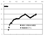
- constants are set so that the response of the equivalent circuit model and the measured value (voltage response value) of the secondary battery 14 substantially coincide. be able to.
- circles indicate actual measurement values
- squares indicate the response of the equivalent circuit model.
- the CPU 10a obtains the element value Rct1 of the resistance component and the element value C1 of the capacitance component shown in FIG. 4 from the element values of the equivalent circuit optimized as described above.
- the CPU 10a applies the acquired value of Rct1 to, for example, a predetermined function f (Rct1), and calculates an index value for identifying the type of the secondary battery 14.
- f (Rct1) for calculating the index value for example, the following formula (1) can be used.
- the CPU 10a compares the index value f (Rct1) obtained as described above with 1 / C1, and when 1 / C1 exceeds the index value f (Rct1), the secondary battery 14 is, for example, idling stopped.
- the secondary battery 14 is determined to be a dedicated secondary battery and 1 / C1 does not exceed the index value f (Rct1), the secondary battery 14 is determined to be, for example, a normal liquid type secondary battery.
- the determination is made using Rct1 and C1, but other values (for example, Rct2 and C2) may be used.
- Rct1, Rct2, C1, and C2 may be used in combination, or Rct1 and C2, and Rct2 and C1 may be used in combination.
- the horizontal axis indicates the resistance Rct
- the curve shown as the separation curve shows the index value f (Rct) described above.
- the secondary battery existing above the separation curve (upper side of the figure) is dedicated to idling stop
- the detection formula fistp () dedicated to idling stop is acquired from the ROM 10b, and is equivalent to the acquired detection formula fistp ().
- a circuit constant (element value) is substituted to detect the state of the secondary battery 14.
- the detection formula fnrml () dedicated to the normal liquid type is acquired from the ROM 10b, and an equivalent circuit of the detected detection type fnrml () is obtained. A constant is substituted and the state of the secondary battery 14 is detected.
- the state of the secondary battery 14 detected from the constant of the equivalent circuit model includes, for example, the initial capacity, the deteriorated capacity, the remaining discharge capacity, the response voltage with respect to a predetermined required current, and the like.
- the initial capacity (SOH_ini) when taken as an example, it can be calculated by the following equation.
- the constants Const 1 to 6 of the formula (2) can be optimally determined for each type of secondary battery to be identified. Different calculation formulas can be used depending on the type of the secondary battery.
- the calculation formula for correcting the temperature dependence and SOC (State Of Charge) dependence of the constants of the equivalent circuit model can be optimized for each type of secondary battery based on the same concept.
- the calculation formulas and coefficients for correction calculation are stored for each type of secondary battery and corrected using the formulas and coefficients corresponding to the identified secondary battery type. Calculations can be made.
- the type of the secondary battery 14 is identified based on the constants of the equivalent circuit model, and the detection formula corresponding to the identified type is used to Since the state of the secondary battery 14 is detected, the state can be accurately detected regardless of the type of the secondary battery 14.
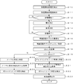
- FIG. 7 is a flowchart illustrating an example of processing executed in the first embodiment.
- the processing in this figure is executed when, for example, an ignition switch (not shown) is operated. Of course, other timings may be used.
- step S10 the CPU 10a acquires from the voltage sensor 11 a voltage before the start of discharge, that is, a voltage before the starter motor 18 starts rotating.
- step S11 the CPU 10a acquires from the current sensor 12 the current before the start of discharge, that is, the current before the starter motor 18 starts rotating.
- step S12 the CPU 10a determines whether or not the discharge is started. If it is determined that the discharge is started (step S12: Yes), the process proceeds to step S13, and otherwise (step S12: No). In such a case, the same processing is repeated. For example, when the rotation of the starter motor 18 is started, it is determined as Yes and the process proceeds to step S13.
- step S13 the CPU 10a refers to the output of the voltage sensor 11 and measures the voltage of the secondary battery 14.
- step S14 the CPU 10a refers to the output of the current sensor 12 and measures the current of the secondary battery 14.
- step S15 the CPU 10a determines whether or not the discharge has ended. If it is determined that the discharge has ended (step S15: Yes), the process proceeds to step S16, and otherwise (step S15: No). In step S13, the same processing is repeated.
- the determination as to whether or not the discharge has ended can be made, for example, by determining whether the rotation of the starter motor 18 has stopped, the engine 17 has been started, or the ignition switch has been restored from the start position. .
- step S16 the CPU 10a executes optimization of each element of the equivalent circuit model.
- an optimal state vector X is estimated by an extended Kalman filter operation, and an adjustment parameter of the equivalent circuit is estimated from the estimated state vector X. (Element value) is updated to an optimum value.
- a voltage drop ⁇ V when the secondary battery is discharged with a predetermined current pattern is calculated, and this approaches a measured value.
- the state vector X is updated as follows. Then, an optimal adjustment parameter is calculated from the state vector X optimized by the update.
- step S17 the CPU 10a acquires, for example, Rct1 and C1 among the constants of the equivalent circuit model optimized in step S16.
- step S18 the CPU 10a applies the constant Rct1 to the function f (Rct1), and calculates an index value for identifying the type of the secondary battery 14.
- the function f (Rct1) for calculating the index value for example, the above-described equation (1) can be used.
- step S19 the CPU 10a compares the index value calculated in step S18 with 1 / C1, and if 1 / C1> f (Rct1) is satisfied (step S19: Yes), the process proceeds to step S20. In the case (step S19: No), the process proceeds to step S24.
- step S20 the CPU 10a determines that the secondary battery 14 is dedicated to idling stop.
- step S21 the CPU 10a acquires a detection formula fistp dedicated to idling stop from the ROM 10b.
- the detection formula fistp dedicated to the idling stop is a formula specialized for the secondary battery dedicated to the idling stop. By using this formula, the state of the secondary battery dedicated to the idling stop can be accurately detected. .
- step S22 the CPU 10a detects the state of the secondary battery dedicated for idling stop based on the detection formula fistp acquired in step S21.
- the state to be detected includes, for example, an initial capacity, a deteriorated capacity, a remaining discharge capacity, a response voltage with respect to a predetermined required current, and the like.
- the initial capacity (SOH_ini) is taken as an example, it can be calculated by the above-described equation (2).
- step S23 the CPU 10a outputs the detection result of the secondary battery 14 calculated in step S22.
- step S24 the CPU 10a determines that the secondary battery 14 is a normal liquid type.
- step S25 the CPU 10a acquires the detection formula fnrml dedicated to the normal liquid type from the ROM 10b.
- the detection type fnrml dedicated to the normal liquid type is an expression specialized for the normal liquid type secondary battery. By using this formula, the state of the normal liquid type secondary battery can be accurately detected. it can.
- step S26 the CPU 10a detects the state of the normal liquid type secondary battery based on the detection formula fnrml acquired in step S25.
- the state to be detected includes, for example, an initial capacity, a deteriorated capacity, a remaining discharge capacity, a response voltage with respect to a predetermined required current, and the like.
- the initial capacity (SOH_ini) is taken as an example, it can be calculated by the above-described equation (2).
- the state of the normal liquid type secondary battery obtained in this way is output in step S23.
- the second embodiment has the same configuration as that of the first embodiment, but a part of the processing executed in the control unit 10 is different from that of the first embodiment. Therefore, the following description will focus on parts that are different from the first embodiment.
- the type of the secondary battery 14 is identified based on the index value f (Rct1).
- the secondary battery 14 is based on the supervised learning model. Identify the type.
- the supervised learning process for example, a neural network or a support vector machine can be used. In the following, a case where a neural network is used will be described as an example.
- a lead storage battery As a kind of secondary battery to identify, there exist a lead storage battery, a nickel metal hydride battery, a lithium ion battery, and a nickel cadmium battery, for example. Moreover, you may make it identify whether it is any of the liquid storage battery of a lead storage battery, a seal-type storage battery, and the storage battery for idling stops, or any of these new articles or used articles.
- the type of the secondary battery 14 is identified using a neural network that has been learned in advance.
- the equivalent circuit model is optimized, and the constant of the equivalent circuit shown in FIG. 4 obtained by the optimization is input to the neural network to identify the type of the secondary battery 14.
- Information is output.
- the secondary battery 14 is a lead storage battery for idling stop
- the constants Rohm, Rct1, C1, Rct2, and C2 of the elements constituting the equivalent circuit model is output.
- a detection formula corresponding to the specified type is acquired from the ROM 10b, and constants of elements constituting the equivalent circuit model are substituted into the detection formula, and the state of the secondary battery 14 is determined. Is detected.
- a detection formula corresponding to the lead-acid storage battery for idling stop is acquired from the ROM 10b, and for example, the constants Rohm, Rct1, C1, Rct2, of the elements constituting the equivalent circuit model are obtained with respect to this detection formula.
- C2 is substituted and the state of the secondary battery 14 is detected. According to such a process, it becomes possible to increase the identification rate of the type of the secondary battery as compared with the first embodiment described above. For this reason, it is possible to accurately detect the states of a plurality of types of secondary batteries.
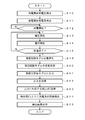
- steps S10 to S16 as in the case described above, the voltage value and the current value when the starter motor 18 is rotated are measured at predetermined intervals and stored in the RAM 10c.
- the equivalent circuit model is optimized based on the voltage value and the current value stored in the RAM 10c.
- step S40 the CPU 10a acquires a constant of the equivalent circuit model. For example, at least a part of constants Rohm, Rct1, C1, Rct2, and C2 of the elements constituting the equivalent circuit model is acquired.
- step S41 the CPU 10a inputs the constant acquired in step S40 into a supervised learning model that has been previously learned.
- a supervised learning model exists as the supervised learning model, and in the process of step S41, the CPU 10a makes the element constants Rohm, Rct1, C1, Rct2, and C2 of the element acquired in step S40 to the neural network. At least some constants are entered.
- step S42 the CPU 10a acquires the output of the supervised learning model. For example, when a constant of the equivalent circuit of the lead-acid battery dedicated to idling stop is input, information indicating that the lead-acid battery is dedicated to idling stop is output. In step S42, this information is acquired.
- step S43 the CPU 10a acquires the detection formula f () corresponding to the output acquired in step S42 from the ROM 10b. For example, when information indicating that the lead-acid battery is dedicated to idling stop is output, the detection formula f () corresponding to the lead-acid battery dedicated to idling stop is acquired from the ROM 10b.
- step S44 the CPU 10a detects the state of the secondary battery based on the detection formula f () acquired in step S43.
- the detected state includes, for example, an initial capacity, a deteriorated capacity, a remaining discharge capacity, a response voltage with respect to a predetermined required current, and the like.
- the initial capacity (SOH_ini) is taken as an example, it can be calculated by the above-described equation (2).
- step S23 the CPU 10a outputs the state of the secondary battery obtained in step S44.
- the type of the secondary battery 14 is identified using the supervised learning model, and the state of the secondary battery 14 is detected using the detection formula corresponding to the identification result. Regardless of the type of the battery 14, it is possible to accurately detect the state.
- the type of the secondary battery 14 is determined based on the relationship between the constants Rtc1 and C1, but it may be determined using other constants. Further, instead of using two types of constants, determination may be made using three or more constants. Further, although the function shown in the expression (1) is used for identification, for example, the ratio of two constants (for example, the ratio of Rohm to Rct1) is determined by comparing with a predetermined threshold. Also good. More specifically, Rohm / Rct1, Rct1 / Rct2, Rct1 / C1,... May be identified by comparison with a threshold value obtained in advance through experiments.
- the identification index may be calculated using different calculation formulas using constants of different equivalent circuit models depending on the type of the secondary battery to be identified. Further, the identification index may be calculated using constants of a plurality of equivalent circuit models, or may be performed as a discrimination method depending on whether or not a predetermined threshold value obtained in advance through experiments or the like is exceeded.
- the type of the secondary battery 14 is determined to be the normal liquid type or the idling stop type, but other types may be determined. For example, the initial capacity, manufacturer, and model number of the secondary battery 14 may be identified.
- the case where the initial capacity (SOH_ini) of the secondary battery 14 is obtained has been described as an example.
- the deterioration capacity, the remaining discharge capacity, and a predetermined required current It is also possible to obtain the response voltage.
- a formula for obtaining these a formula similar to the formula (2) described above or a function using at least a part of the elements of the equivalent circuit model can be used.
- the type of the secondary battery 14 is identified using a neural network, but other supervised learning models may be used.
- a support vector machine may be used.
- the separation curve in the teacher data so that the minimum value of the distance from the separation curve to each sample point of the teacher data is maximized (so that the margin is maximized). Can determine a separation curve with high discrimination power.
- the constants of the equivalent circuit model are learned for a known type of secondary battery, and a separated hyperplane / hypersurface is obtained by supervised learning using the known data as teacher data.
- a method of identifying using a hyperplane or a hypersurface may be used.
- the equivalent circuit model is optimized based on changes in voltage and current when the starter motor 18 is rotated. However, based on the current flowing to a load other than the starter motor 18. May be optimized. For example, the discharge circuit 15 may be switched, the voltage and current of the secondary battery 14 at that time may be detected, and the equivalent circuit model may be optimized based on the detected voltage and current.
- the model shown in FIG. 4 is used as the equivalent circuit model.
- other equivalent circuit models may be used.
- an equivalent circuit model in which three or more stages of resistance elements and capacitance elements connected in parallel are connected in series may be used.
- other equivalent circuit models may be used.
- FIGS. 7 and 9 are examples, and the processes may be executed in an order other than this, or other processes may be executed.
- only the state detection of the secondary battery 14 is performed. For example, based on the obtained state, for example, the idling stop execution of stopping the engine 17 is stopped. You may make it control. Specifically, when the SOC of the secondary battery 14 is higher than a predetermined threshold, idling stop is executed, and when it is determined that the SOC is lower than the predetermined threshold, idling stop is not executed. Also good. Moreover, when SOH is approaching a predetermined threshold value, for example, the operation of the load 19 may be stopped to prevent further consumption of the secondary battery 14. Furthermore, when SOH is smaller than a predetermined threshold, a message instructing to replace the secondary battery 14 may be displayed.
Landscapes
- Engineering & Computer Science (AREA)
- Power Engineering (AREA)
- General Physics & Mathematics (AREA)
- Physics & Mathematics (AREA)
- Chemical Kinetics & Catalysis (AREA)
- General Chemical & Material Sciences (AREA)
- Electrochemistry (AREA)
- Chemical & Material Sciences (AREA)
- Manufacturing & Machinery (AREA)
- Health & Medical Sciences (AREA)
- General Health & Medical Sciences (AREA)
- Medical Informatics (AREA)
- Secondary Cells (AREA)
- Tests Of Electric Status Of Batteries (AREA)
- Charge And Discharge Circuits For Batteries Or The Like (AREA)
Abstract
Le problème décrit par l'invention est de détecter l'état d'une pluralité de piles secondaires de différents types avec une précision élevée. La solution de la présente invention comprend : un moyen de mesure (capteur de tension (11), capteur de courant électrique (12)) pour mesurer, à une fréquence prédéterminée, la valeur de courant électrique d'un courant électrique circulant vers une pile secondaire (14) et la valeur de tension d'une tension produite dans la pile secondaire par le courant électrique ; un moyen d'optimisation (CPU (10a)) pour optimiser une constante de composant d'un modèle de circuit équivalent d'une pile secondaire sur la base de la valeur de tension et de la valeur de courant électrique mesurées ; un moyen d'identification (CPU (10a)) pour identifier le type de pile secondaire avec référence à la constante de composant du modèle de circuit équivalent optimisé ; un moyen de stockage (ROM (10b)) pour stocker une formule de détection servant à détecter l'état d'une pile secondaire pour chaque type de pile secondaire ; un moyen d'acquisition (CPU (10a)) pour acquérir la formule de détection correspondant au type identifié auprès du moyen de stockage ; et un moyen de détection (CPU (10a)) pour détecter l'état d'une pile secondaire par application de la constante de composant à la formule de détection acquise.
Priority Applications (3)
| Application Number | Priority Date | Filing Date | Title |
|---|---|---|---|
| EP14762948.9A EP2955533B1 (fr) | 2013-03-14 | 2014-02-12 | Dispositif de détection d'état de pile secondaire et procédé de détection d'état de pile secondaire |
| CN201480013224.4A CN105026945B (zh) | 2013-03-14 | 2014-02-12 | 二次电池状态检测装置及二次电池状态检测方法 |
| US14/852,329 US10466302B2 (en) | 2013-03-14 | 2015-09-11 | Secondary battery state detecting device and secondary battery state detecting method |
Applications Claiming Priority (2)
| Application Number | Priority Date | Filing Date | Title |
|---|---|---|---|
| JP2013052571A JP5810116B2 (ja) | 2013-03-14 | 2013-03-14 | 二次電池状態検出装置および二次電池状態検出方法 |
| JP2013-052571 | 2013-03-14 |
Related Child Applications (1)
| Application Number | Title | Priority Date | Filing Date |
|---|---|---|---|
| US14/852,329 Continuation US10466302B2 (en) | 2013-03-14 | 2015-09-11 | Secondary battery state detecting device and secondary battery state detecting method |
Publications (1)
| Publication Number | Publication Date |
|---|---|
| WO2014141796A1 true WO2014141796A1 (fr) | 2014-09-18 |
Family
ID=51536472
Family Applications (1)
| Application Number | Title | Priority Date | Filing Date |
|---|---|---|---|
| PCT/JP2014/053135 WO2014141796A1 (fr) | 2013-03-14 | 2014-02-12 | Dispositif de détection d'état de pile secondaire et procédé de détection d'état de pile secondaire |
Country Status (5)
| Country | Link |
|---|---|
| US (1) | US10466302B2 (fr) |
| EP (1) | EP2955533B1 (fr) |
| JP (1) | JP5810116B2 (fr) |
| CN (1) | CN105026945B (fr) |
| WO (1) | WO2014141796A1 (fr) |
Cited By (2)
| Publication number | Priority date | Publication date | Assignee | Title |
|---|---|---|---|---|
| JP2019023995A (ja) * | 2017-05-03 | 2019-02-14 | 株式会社半導体エネルギー研究所 | 蓄電装置、半導体装置、icチップ、電子機器 |
| CN116774077A (zh) * | 2023-06-21 | 2023-09-19 | 广东电网有限责任公司 | 储能电站电池的健康检测方法、装置、设备及存储介质 |
Families Citing this family (35)
| Publication number | Priority date | Publication date | Assignee | Title |
|---|---|---|---|---|
| JP5798067B2 (ja) * | 2012-03-13 | 2015-10-21 | プライムアースEvエナジー株式会社 | 二次電池の状態推定装置 |
| WO2014136593A1 (fr) * | 2013-03-07 | 2014-09-12 | 古河電気工業株式会社 | Dispositif de détection d'état de batterie secondaire et procédé de détection d'état de batterie secondaire |
| JP6555773B2 (ja) * | 2014-11-18 | 2019-08-07 | 学校法人立命館 | 蓄電残量推定装置、蓄電池の蓄電残量を推定する方法、及びコンピュータプログラム |
| JP6490414B2 (ja) * | 2014-12-05 | 2019-03-27 | 古河電気工業株式会社 | 二次電池状態検出装置および二次電池状態検出方法 |
| CN107210498B (zh) * | 2015-02-12 | 2019-11-05 | 松下知识产权经营株式会社 | 电池类型判定装置和电池类型判定方法 |
| JP6702672B2 (ja) * | 2015-09-03 | 2020-06-03 | キヤノン株式会社 | インプリント装置、物品の製造方法及び供給装置 |
| JP6606996B2 (ja) | 2015-11-24 | 2019-11-20 | 株式会社Gsユアサ | 電池システム、二次電池の電池監視装置および二次電池の監視方法 |
| KR101772036B1 (ko) * | 2015-12-30 | 2017-08-28 | 주식회사 효성 | 배터리 수명 추정 방법 및 장치 |
| JP2017138881A (ja) | 2016-02-05 | 2017-08-10 | ファナック株式会社 | 操作メニューの表示を学習する機械学習器,数値制御装置,工作機械システム,製造システムおよび機械学習方法 |
| JP6898479B2 (ja) * | 2016-02-05 | 2021-07-07 | ファナック株式会社 | 操作メニューの表示を学習する機械学習器,数値制御装置,工作機械システム,製造システムおよび機械学習方法 |
| US10436845B2 (en) * | 2016-03-01 | 2019-10-08 | Faraday & Future Inc. | Electric vehicle battery monitoring system |
| JP6615011B2 (ja) | 2016-03-09 | 2019-12-04 | 日立オートモティブシステムズ株式会社 | 電池管理システム、電池システムおよびハイブリッド車両制御システム |
| DE102016206538A1 (de) * | 2016-04-19 | 2017-10-19 | Audi Ag | Verfahren zum Bestimmen eines Ladezustands einer Batterie für ein Kraftfahrzeug, Vorrichtung sowie Kraftfahrzeug |
| CN107340476B (zh) * | 2016-04-29 | 2021-01-26 | 株式会社日立制作所 | 电池的电气状态监测系统和电气状态监测方法 |
| JP6729714B2 (ja) * | 2016-11-07 | 2020-07-29 | 日産自動車株式会社 | 短絡検出装置 |
| KR102035679B1 (ko) * | 2016-11-29 | 2019-10-23 | 주식회사 엘지화학 | 배터리 노화상태 산출 방법 및 시스템 |
| JP6895786B2 (ja) * | 2017-03-29 | 2021-06-30 | 古河電気工業株式会社 | 二次電池状態検出装置および二次電池状態検出方法 |
| JP6904176B2 (ja) * | 2017-09-01 | 2021-07-14 | トヨタ自動車株式会社 | 二次電池の再利用方法および二次電池システム |
| JP2019158831A (ja) * | 2018-03-16 | 2019-09-19 | 株式会社Gsユアサ | 検査方法、検査装置及び学習モデル |
| JP7072414B2 (ja) * | 2018-03-20 | 2022-05-20 | 古河電気工業株式会社 | 充電可能電池状態検出装置および充電可能電池状態検出方法 |
| US10996282B2 (en) | 2018-03-20 | 2021-05-04 | Gs Yuasa International Ltd. | Abnormality factor determination apparatus, degradation determination apparatus, computer program, degradation determining method, and abnormality factor determining method |
| US11413802B2 (en) | 2018-03-22 | 2022-08-16 | Honda Motor Co., Ltd. | Reusable mold for injection molding and molding method |
| US11085971B2 (en) * | 2018-03-28 | 2021-08-10 | Toyo System Co., Ltd. | Degradation state determination device and degradation state determination method |
| JP7145035B2 (ja) * | 2018-10-29 | 2022-09-30 | 本田技研工業株式会社 | 学習装置、学習方法、及びプログラム |
| KR20200117794A (ko) * | 2019-04-05 | 2020-10-14 | 주식회사 엘지화학 | 배터리 관리 장치 및 방법 |
| CN109900937B (zh) * | 2019-04-10 | 2020-12-08 | 河南科技大学 | 一种具有温度补偿功能的锂电池电荷状态估算方法 |
| US11472083B2 (en) | 2019-09-25 | 2022-10-18 | Honda Motor Co., Ltd. | Injection mold master unit die back plate cooling with metal backfilled plastic mold |
| EP3885776B1 (fr) * | 2020-03-24 | 2024-01-17 | Siemens Aktiengesellschaft | Procédé, outil mis en oeuvre par ordinateur et système de gestion de batterie pour estimer des états de batteries de stockage d'énergie électrique et système de stockage d'énergie de batterie |
| JP6997473B2 (ja) * | 2020-04-13 | 2022-02-04 | 東洋システム株式会社 | 二次電池検査方法および二次電池検査装置 |
| JP7448201B2 (ja) * | 2020-05-21 | 2024-03-12 | アクソンデータマシン株式会社 | 人工知能技術を用いた2次電池の状態推定装置 |
| TWI741632B (zh) * | 2020-06-03 | 2021-10-01 | 龍華科技大學 | 電池智能分流模組之電阻溫度係數預測方法、電流量測補償校正方法及其裝置 |
| CN111856299A (zh) * | 2020-07-29 | 2020-10-30 | 中国联合网络通信集团有限公司 | 电源状态的确定方法、装置及设备 |
| JP2022139501A (ja) * | 2021-03-12 | 2022-09-26 | 株式会社豊田中央研究所 | 劣化判定装置、劣化判定システム、劣化判定方法及びそのプログラム |
| DE102022112886A1 (de) | 2022-05-23 | 2023-11-23 | Volkswagen Aktiengesellschaft | Verfahren zum Prognostizieren eines Batteriezustands einer Batterie eines Kraftfahrzeugs, ein Batteriesystem und ein Kraftfahrzeug |
| CN116929437B (zh) * | 2023-09-15 | 2023-12-08 | 深圳和润达科技有限公司 | 应用于电芯化成分容系统的传感器信息识别方法及装置 |
Citations (6)
| Publication number | Priority date | Publication date | Assignee | Title |
|---|---|---|---|---|
| JPH03183328A (ja) * | 1989-12-11 | 1991-08-09 | Canon Inc | 電池残量演算装置 |
| JPH09166652A (ja) * | 1995-12-15 | 1997-06-24 | Mk Seiko Co Ltd | バッテリー診断方法およびそれを用いたバッテリー診断装置 |
| JP2005221487A (ja) | 2004-02-09 | 2005-08-18 | Furukawa Electric Co Ltd:The | 二次電池の内部インピーダンス測定方法、二次電池の内部インピーダンス測定装置、二次電池劣化判定装置及び電源システム |
| JP2007187534A (ja) | 2006-01-12 | 2007-07-26 | Furukawa Electric Co Ltd:The | バッテリ放電能力判定方法、バッテリ放電能力判定装置、及び電源システム |
| JP2009244180A (ja) | 2008-03-31 | 2009-10-22 | Furukawa Electric Co Ltd:The | バッテリ状態検知方法及びバッテリ状態検知装置 |
| JP2012132724A (ja) * | 2010-12-20 | 2012-07-12 | Furukawa Electric Co Ltd:The | 満充電検知装置および満充電検知方法 |
Family Cites Families (8)
| Publication number | Priority date | Publication date | Assignee | Title |
|---|---|---|---|---|
| JP2000023374A (ja) * | 1998-06-30 | 2000-01-21 | Fuji Photo Film Co Ltd | 二次電池の識別装置および方法 |
| US8033686B2 (en) * | 2006-03-28 | 2011-10-11 | Wireless Environment, Llc | Wireless lighting devices and applications |
| US8078324B2 (en) * | 2007-07-13 | 2011-12-13 | Cummins Inc. | Method for controlling fixed and removable vehicle HVAC devices |
| WO2010056303A1 (fr) * | 2008-11-12 | 2010-05-20 | Bravo Zulu International Ltd. | Désulfatation de batterie au plomb-acide |
| JP4744622B2 (ja) * | 2009-07-01 | 2011-08-10 | トヨタ自動車株式会社 | 車両の制御装置 |
| JP5493657B2 (ja) * | 2009-09-30 | 2014-05-14 | 新神戸電機株式会社 | 蓄電池装置並びに蓄電池の電池状態評価装置及び方法 |
| JP4689756B1 (ja) * | 2010-03-31 | 2011-05-25 | 古河電気工業株式会社 | 電池内部状態推定装置および電池内部状態推定方法 |
| US10664562B2 (en) * | 2013-02-24 | 2020-05-26 | Fairchild Semiconductor Corporation and University of Connecticut | Battery state of charge tracking, equivalent circuit selection and benchmarking |
-
2013
- 2013-03-14 JP JP2013052571A patent/JP5810116B2/ja active Active
-
2014
- 2014-02-12 CN CN201480013224.4A patent/CN105026945B/zh active Active
- 2014-02-12 EP EP14762948.9A patent/EP2955533B1/fr active Active
- 2014-02-12 WO PCT/JP2014/053135 patent/WO2014141796A1/fr active Application Filing
-
2015
- 2015-09-11 US US14/852,329 patent/US10466302B2/en active Active
Patent Citations (7)
| Publication number | Priority date | Publication date | Assignee | Title |
|---|---|---|---|---|
| JPH03183328A (ja) * | 1989-12-11 | 1991-08-09 | Canon Inc | 電池残量演算装置 |
| JPH09166652A (ja) * | 1995-12-15 | 1997-06-24 | Mk Seiko Co Ltd | バッテリー診断方法およびそれを用いたバッテリー診断装置 |
| JP2005221487A (ja) | 2004-02-09 | 2005-08-18 | Furukawa Electric Co Ltd:The | 二次電池の内部インピーダンス測定方法、二次電池の内部インピーダンス測定装置、二次電池劣化判定装置及び電源システム |
| JP2007187534A (ja) | 2006-01-12 | 2007-07-26 | Furukawa Electric Co Ltd:The | バッテリ放電能力判定方法、バッテリ放電能力判定装置、及び電源システム |
| JP4532416B2 (ja) | 2006-01-12 | 2010-08-25 | 古河電気工業株式会社 | バッテリ放電能力判定方法、バッテリ放電能力判定装置、及び電源システム |
| JP2009244180A (ja) | 2008-03-31 | 2009-10-22 | Furukawa Electric Co Ltd:The | バッテリ状態検知方法及びバッテリ状態検知装置 |
| JP2012132724A (ja) * | 2010-12-20 | 2012-07-12 | Furukawa Electric Co Ltd:The | 満充電検知装置および満充電検知方法 |
Non-Patent Citations (1)
| Title |
|---|
| See also references of EP2955533A4 |
Cited By (4)
| Publication number | Priority date | Publication date | Assignee | Title |
|---|---|---|---|---|
| JP2019023995A (ja) * | 2017-05-03 | 2019-02-14 | 株式会社半導体エネルギー研究所 | 蓄電装置、半導体装置、icチップ、電子機器 |
| US11594770B2 (en) | 2017-05-03 | 2023-02-28 | Semiconductor Energy Laboratory Co., Ltd. | Neural network, power storage system, vehicle, and electronic device |
| US11955612B2 (en) | 2017-05-03 | 2024-04-09 | Semiconductor Energy Laboratory Co., Ltd. | Neural network, power storage system, vehicle, and electronic device |
| CN116774077A (zh) * | 2023-06-21 | 2023-09-19 | 广东电网有限责任公司 | 储能电站电池的健康检测方法、装置、设备及存储介质 |
Also Published As
| Publication number | Publication date |
|---|---|
| US10466302B2 (en) | 2019-11-05 |
| JP2014178213A (ja) | 2014-09-25 |
| JP5810116B2 (ja) | 2015-11-11 |
| EP2955533A4 (fr) | 2016-06-15 |
| US20160003912A1 (en) | 2016-01-07 |
| EP2955533A1 (fr) | 2015-12-16 |
| EP2955533B1 (fr) | 2017-05-17 |
| CN105026945A (zh) | 2015-11-04 |
| CN105026945B (zh) | 2017-12-05 |
Similar Documents
| Publication | Publication Date | Title |
|---|---|---|
| JP5810116B2 (ja) | 二次電池状態検出装置および二次電池状態検出方法 | |
| US11163010B2 (en) | Secondary battery deterioration estimation device and secondary battery deterioration estimation method | |
| JP6479650B2 (ja) | 二次電池状態検出装置および二次電池状態検出方法 | |
| US10436847B2 (en) | Secondary battery state detection device and secondary battery state detection method | |
| US9134381B2 (en) | Predicting state of a battery | |
| JP4645382B2 (ja) | バッテリ状態検知装置、バッテリ状態検知方法 | |
| JP5349810B2 (ja) | 蓄電装置の異常検出装置及び方法並びにプログラム | |
| US11143710B2 (en) | Device for estimating degradation of secondary cell, and method for estimating degradation of secondary cell | |
| JP6277864B2 (ja) | 電池内部状態推定装置 | |
| US10393814B2 (en) | Secondary battery state detection device and secondary battery state detection method | |
| CN109874354B (zh) | 二次电池状态检测装置和二次电池状态检测方法 | |
| EP3551494B1 (fr) | Procede permettant l'estimation de l'etat de charge d'une batterie | |
| JP6575308B2 (ja) | 内部抵抗算出装置、コンピュータプログラム及び内部抵抗算出方法 | |
| JP5653881B2 (ja) | 二次電池状態検出装置および二次電池状態検出方法 | |
| JP6498920B2 (ja) | 二次電池状態検出装置および二次電池状態検出方法 | |
| US20160109527A1 (en) | Method and apparatus for determining a change in resistance of an energy storage device and vehicle | |
| US20230324463A1 (en) | Method and Apparatus for Operating a System for Detecting an Anomaly of an Electrical Energy Store for a Device by Means of Machine Learning Methods |
Legal Events
| Date | Code | Title | Description |
|---|---|---|---|
| WWE | Wipo information: entry into national phase |
Ref document number: 201480013224.4 Country of ref document: CN |
|
| 121 | Ep: the epo has been informed by wipo that ep was designated in this application |
Ref document number: 14762948 Country of ref document: EP Kind code of ref document: A1 |
|
| REEP | Request for entry into the european phase |
Ref document number: 2014762948 Country of ref document: EP |
|
| WWE | Wipo information: entry into national phase |
Ref document number: 2014762948 Country of ref document: EP |
|
| NENP | Non-entry into the national phase |
Ref country code: DE |