WO2014136540A1 - ターボ冷凍機用圧縮機のオイルタンクおよびターボ冷凍機用圧縮機 - Google Patents
ターボ冷凍機用圧縮機のオイルタンクおよびターボ冷凍機用圧縮機 Download PDFInfo
- Publication number
- WO2014136540A1 WO2014136540A1 PCT/JP2014/053255 JP2014053255W WO2014136540A1 WO 2014136540 A1 WO2014136540 A1 WO 2014136540A1 JP 2014053255 W JP2014053255 W JP 2014053255W WO 2014136540 A1 WO2014136540 A1 WO 2014136540A1
- Authority
- WO
- WIPO (PCT)
- Prior art keywords
- compressor
- turbo refrigerator
- oil tank
- heater
- bottom plate
- Prior art date
- Legal status (The legal status is an assumption and is not a legal conclusion. Google has not performed a legal analysis and makes no representation as to the accuracy of the status listed.)
- Ceased
Links
Images
Classifications
-
- F—MECHANICAL ENGINEERING; LIGHTING; HEATING; WEAPONS; BLASTING
- F04—POSITIVE - DISPLACEMENT MACHINES FOR LIQUIDS; PUMPS FOR LIQUIDS OR ELASTIC FLUIDS
- F04D—NON-POSITIVE-DISPLACEMENT PUMPS
- F04D29/00—Details, component parts, or accessories
- F04D29/06—Lubrication
- F04D29/063—Lubrication specially adapted for elastic fluid pumps
-
- F—MECHANICAL ENGINEERING; LIGHTING; HEATING; WEAPONS; BLASTING
- F04—POSITIVE - DISPLACEMENT MACHINES FOR LIQUIDS; PUMPS FOR LIQUIDS OR ELASTIC FLUIDS
- F04D—NON-POSITIVE-DISPLACEMENT PUMPS
- F04D29/00—Details, component parts, or accessories
- F04D29/40—Casings; Connections of working fluid
- F04D29/42—Casings; Connections of working fluid for radial or helico-centrifugal pumps
- F04D29/4206—Casings; Connections of working fluid for radial or helico-centrifugal pumps especially adapted for elastic fluid pumps
-
- F—MECHANICAL ENGINEERING; LIGHTING; HEATING; WEAPONS; BLASTING
- F04—POSITIVE - DISPLACEMENT MACHINES FOR LIQUIDS; PUMPS FOR LIQUIDS OR ELASTIC FLUIDS
- F04D—NON-POSITIVE-DISPLACEMENT PUMPS
- F04D29/00—Details, component parts, or accessories
- F04D29/58—Cooling; Heating; Diminishing heat transfer
- F04D29/582—Cooling; Heating; Diminishing heat transfer specially adapted for elastic fluid pumps
- F04D29/584—Cooling; Heating; Diminishing heat transfer specially adapted for elastic fluid pumps cooling or heating the machine
-
- F—MECHANICAL ENGINEERING; LIGHTING; HEATING; WEAPONS; BLASTING
- F04—POSITIVE - DISPLACEMENT MACHINES FOR LIQUIDS; PUMPS FOR LIQUIDS OR ELASTIC FLUIDS
- F04D—NON-POSITIVE-DISPLACEMENT PUMPS
- F04D29/00—Details, component parts, or accessories
- F04D29/58—Cooling; Heating; Diminishing heat transfer
- F04D29/582—Cooling; Heating; Diminishing heat transfer specially adapted for elastic fluid pumps
- F04D29/5853—Cooling; Heating; Diminishing heat transfer specially adapted for elastic fluid pumps heat insulation or conduction
-
- F—MECHANICAL ENGINEERING; LIGHTING; HEATING; WEAPONS; BLASTING
- F25—REFRIGERATION OR COOLING; COMBINED HEATING AND REFRIGERATION SYSTEMS; HEAT PUMP SYSTEMS; MANUFACTURE OR STORAGE OF ICE; LIQUEFACTION SOLIDIFICATION OF GASES
- F25B—REFRIGERATION MACHINES, PLANTS OR SYSTEMS; COMBINED HEATING AND REFRIGERATION SYSTEMS; HEAT PUMP SYSTEMS
- F25B1/00—Compression machines, plants or systems with non-reversible cycle
- F25B1/04—Compression machines, plants or systems with non-reversible cycle with compressor of rotary type
- F25B1/053—Compression machines, plants or systems with non-reversible cycle with compressor of rotary type of turbine type
-
- F—MECHANICAL ENGINEERING; LIGHTING; HEATING; WEAPONS; BLASTING
- F25—REFRIGERATION OR COOLING; COMBINED HEATING AND REFRIGERATION SYSTEMS; HEAT PUMP SYSTEMS; MANUFACTURE OR STORAGE OF ICE; LIQUEFACTION SOLIDIFICATION OF GASES
- F25B—REFRIGERATION MACHINES, PLANTS OR SYSTEMS; COMBINED HEATING AND REFRIGERATION SYSTEMS; HEAT PUMP SYSTEMS
- F25B31/00—Compressor arrangements
- F25B31/002—Lubrication
-
- F—MECHANICAL ENGINEERING; LIGHTING; HEATING; WEAPONS; BLASTING
- F25—REFRIGERATION OR COOLING; COMBINED HEATING AND REFRIGERATION SYSTEMS; HEAT PUMP SYSTEMS; MANUFACTURE OR STORAGE OF ICE; LIQUEFACTION SOLIDIFICATION OF GASES
- F25B—REFRIGERATION MACHINES, PLANTS OR SYSTEMS; COMBINED HEATING AND REFRIGERATION SYSTEMS; HEAT PUMP SYSTEMS
- F25B2500/00—Problems to be solved
- F25B2500/16—Lubrication
Definitions
- the present invention relates to an oil tank for a compressor for a turbo refrigerator and a compressor for a turbo refrigerator.
- an oil tank 13 provided with a heater 30 described in FIG. 2 of Patent Document 1, FIG. 1 (A) of Patent Document 2, FIG.
- the oil tank chamber 2 provided with the oil heater 6 described in 2.
- JP 2011-26958 A Japanese Utility Model No. 4-24560
- the present invention has been made to solve the above-mentioned problems, and it is possible to replace or check the heater without recovering the oil existing in the oil tank and the refrigerant existing in the turbo refrigerator. It is an object of the present invention to provide an oil tank for a compressor and a compressor for a turbo refrigerator.
- a first aspect of the present invention comprises a bottom plate and a side plate erected upward from an outer peripheral edge of the bottom plate, and forms a bottom portion of a casing constituting a compressor for a turbo refrigerator.
- the side plate is provided with a through hole penetrating in the plate thickness direction, and a protective pipe whose tip is a closed end is formed in the through hole. While being inserted, a rod-shaped heater configured to be insertable into and removed from the protective tube is inserted into the protective tube.
- replacement or inspection of the heater can be performed simply by inserting and removing the heater from the protective tube. That is, the replacement or inspection of the heater is performed with the protective tube fixed to the side plate that constitutes the oil tank.
- the heater can be replaced or inspected without recovering the oil present in the oil tank and the refrigerant present in the turbo refrigerator.
- the through hole is provided at the lowest part of the side plate.
- the convection of the oil warmed by the heater can be promoted, and the oil in the oil tank can be efficiently warmed.
- a heat transfer fluid having high thermal conductivity be filled between the protective tube and the heater.
- the heat transfer coefficient from the heater to the protective tube can be improved, and a heater with a small output can be employed.
- a second aspect of the present invention comprises a bottom plate and a side plate erected upward from the outer peripheral edge of the bottom plate, and forms a bottom portion of a casing constituting a compressor for a turbo refrigerator.
- An oil tank of the compressor for a turbo refrigerator, and a hole extending from one end surface of the bottom plate to the other end surface opposite to the one end surface is provided in the inside of the bottom plate In the hole, a rod-shaped heater configured to be insertable into and removed from the hole is inserted.
- a heat transfer fluid having high thermal conductivity be filled between the hole and the heater.
- the heat transfer coefficient from the heater to the bottom plate can be improved, and a heater with a small output can be employed.
- a third aspect of the present invention comprises a bottom plate and a side plate erected upward from the outer peripheral edge of the bottom plate, and forms a bottom portion of a casing constituting a compressor for a turbo refrigerator.
- replacement or inspection of the heater is performed only by detaching the heater attached to the outer surface of the bottom plate or the outer surface of the bottom plate and the outer surface of the side plate.
- the heater can be replaced or inspected without recovering the oil present in the oil tank and the refrigerant present in the turbo refrigerator.
- a sheet-like metal having high thermal conductivity be sandwiched between the heater and the outer surface so as to be in close contact with both.
- the heat transfer coefficient from the heater to the outer surface of the oil tank can be improved, and a heater with a small output can be employed.
- the contact area between the bottom plate heated by the heater and the oil can be increased, the oil can be warmed more efficiently, and a heater with a smaller output can be adopted.
- a fourth aspect of the present invention is a compressor for a turbo refrigerator including the oil tank of the compressor for a turbo refrigerator according to any one of the above-mentioned aspects.
- the heater attached to the oil tank can be replaced or inspected without recovering the oil present in the oil tank and the refrigerant present in the turbo refrigerator, so the heater replacement or inspection can be performed.
- the working time required for the service can be significantly reduced, and its availability and reliability can be improved.
- a fifth aspect of the present invention is a turbo refrigerator provided with the above-described compressor for a turbo refrigerator.
- the operation time required to replace or check the heater attached to the oil tank of the compressor for the turbo refrigerator is significantly reduced, so that the operation rate and reliability thereof can be improved. it can.
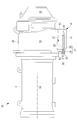
- FIG. 1 a compressor for a turbo refrigerator comprising an oil tank for a compressor for a turbo refrigerator according to a first embodiment of the present invention, and an oil tank for the compressor for a turbo refrigerator according to the first embodiment of the present invention, And the turbo refrigerator provided with the compressor for turbo refrigerators concerning 1st Embodiment of this invention is demonstrated using FIG. As shown in FIG.
- the turbo refrigerator 1A is installed in a building or a factory, for example, to generate cooling water for air conditioning, and is rotationally driven by a motor 2 and is used as a refrigerant vapor Compressor for turbo refrigerator (Turbo type compressor) 3A which compresses to high pressure steam, an evaporator (not shown) for evaporating cold water, and a condenser for cooling and condensing high pressure steam with cooling water ( And an expander (not shown) for decompressing and expanding the condensed refrigerant and sending it to the evaporator.
- the turbo refrigerator compressor 3A, the evaporator, the condenser, and the expander are connected by a refrigerant pipe (not shown) that circulates a refrigerant.
- the oil tank 10 of the compressor 3A for a turbo refrigerator has a bottom plate 11 and a (first) side plate 12 erected upward from the outer peripheral edge of the bottom plate 11, a (second) side plate 13, (third) side plate (not shown), and (fourth) side plate (not shown), and the (first) casing (in the present embodiment, a compressor for a turbo refrigerator)
- the bottom portion (lower portion) of the compressor casing 14 that constitutes the machine 3A is formed.
- the bottom plate 11 is a plate-like member having a rectangular shape in a plan view extending along the axial direction and the left and right direction.
- the side plate 12 is a plate-like member which is located on the side of the (second) casing (in the present embodiment, the motor casing that constitutes the motor 2) 15 attached to one end of the casing 14 and extends along the vertical direction. is there.
- the side plate 13 is located on the side of a (third) casing (in the present embodiment, a compressor inlet casing forming the inlet of the compressor 3A for a turbo refrigerator) 16 attached to the other end of the casing 14 It is a plate-like member extending along the direction.
- a through hole 21 penetrating in the thickness direction is provided in the bottom portion (lower portion) of the side surface plate 12, more preferably, the lowest portion (lowermost portion) of the side surface plate 12, a through hole 21 penetrating in the thickness direction is provided.
- the through hole 21 is located on the front side (outside) of the side plate 12 and receives a first through hole 24 for receiving the female screw portion of the threaded joint 23 provided at the proximal end of the protective tube 22;
- a (second) through hole 25 through which the protective tube 22 is inserted is provided at the back side (inner side) of the T.12.
- a male screw portion to be screwed with a female screw portion provided on the outer peripheral surface of the threaded joint 23 is provided on the inner peripheral surface of the through hole 24, and a heat transfer fluid having a large thermal conductivity (excellent in thermal conductivity) (for example, a heat-resistant and heat-dissipating silicon material) between the protective tube 22 and the heater 26.
- a heat transfer fluid having a large thermal conductivity excellent in thermal conductivity
- the oil tank 10 of the compressor 3A for a turbo refrigerator According to the oil tank 10 of the compressor 3A for a turbo refrigerator according to the present embodiment, that is, the oil tank 10 of the compressor 3A for a turbo refrigerator provided with the heater 26, replacement or inspection of the heater 26 can be performed by the protective pipe 22. However, it is only necessary to remove and insert the heater 26. That is, the replacement or inspection of the heater 26 is performed in a state where the protective pipe 26 is fixed to the side plate 12 constituting the oil tank 10. Thus, the heater 26 can be replaced or checked without recovering the oil 27 present in the oil tank 10 and the refrigerant present in the turbo refrigerator 1A.
- the through hole 21 is formed of the side plate 12 As the lower part is provided, the convection of the oil 27 heated by the heater 26 can be promoted, and the oil 27 in the oil tank 10 can be efficiently heated.
- the oil tank 10 of the compressor 3A for a turbo refrigerator that is, according to the oil tank 10 of the compressor 3A for a turbo refrigerator provided with the heater 26, between the protective pipe 22 and the heater 26.
- the heat transfer fluid having a large thermal conductivity is filled, the heat transfer coefficient from the heater 26 to the protective tube 22 can be improved, and a heater having a small output can be employed.
- the heater 26 attached to the oil tank 10 can be used without recovering the oil 27 present in the oil tank 10 and the refrigerant present in the turbo refrigerator 1A. It can be replaced or checked. Further, according to the compressor 3A for a turbo refrigerator according to the present embodiment, the heater attached to the oil tank 10 without recovering the oil 27 present in the oil tank 10 and the refrigerant present in the turbo refrigerator 1A. Since the H.26 can be replaced or checked, the working time required to replace or check the heater 26 can be greatly reduced, and its operation rate and reliability can be improved.
- the operation time required for replacing or checking the heater 26 attached to the oil tank 10 of the compressor 3A for the turbo refrigerator is significantly reduced, so the operation rate thereof And reliability can be improved.
- the turbo refrigerator 1B is installed in a building or a factory, for example, to generate cooling water for air conditioning, and is rotationally driven by a motor 2 and is a refrigerant vapor Compressor for turbo refrigerator (Turbo type compressor) 3B which compresses to high pressure steam, an evaporator (not shown) for evaporating cold water, and a condenser for cooling and condensing high pressure steam with cooling water ( And an expander (not shown) for decompressing and expanding the condensed refrigerant and sending it to the evaporator.
- the turbo refrigerator compressor 3B, the evaporator, the condenser, and the expander are connected by a refrigerant pipe (not shown) that circulates a refrigerant.
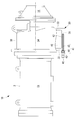
- the oil tank 30 of the compressor 3B for a turbo refrigerator is erected upward from the bottom plate 31 and the outer peripheral edge portion of the bottom plate 31 (first B) a side plate 32, a (second) side plate 33, a (third) side plate (not shown), and a (fourth) side plate (not shown);
- a bottom portion (lower portion) of the casing (in the present embodiment, a compressor casing constituting the turbo compressor 3B) 34 is formed.
- the bottom plate 31 is a plate-like member having a rectangular shape in a plan view extending along the axial direction and the left-right direction.
- the side plate 32 is a plate-like member which is located on the side of the (second) casing (in the present embodiment, the motor casing that constitutes the motor 2) 15 attached to one end of the casing 34 and extends along the vertical direction. is there.
- the side plate 33 is located on the side of the (third) casing (in the present embodiment, the compressor inlet casing forming the inlet of the turbo compressor 3B) 16 attached to the other end of the casing 34 and vertically It is a plate-like member extending along.
- a hole 41 is provided extending along the axial direction towards.
- the hole 41 is located on the front side (the side of the casing 15) of the bottom plate 31 and receives the female screw portion of the screwed joint 43 provided at the base end of the rod-like (electric) heater (heating means) 42 1) and the (second) hole 45 through which the heater 42 is inserted and located on the back side of the bottom plate 31 (the back side of the hole 44).
- an external thread portion to be engaged with an internal thread portion provided on the outer peripheral surface of the threaded joint 43 is provided on the inner peripheral surface of the hole 44.
- a heater 42 is inserted into the inside of the hole 41, and a heat transfer fluid having a large thermal conductivity (excellent in heat conduction) (for example, a heat-resistant heat-dissipating silicon material, a chemical) between the hole 41 and the heater 42 Synthetic oil, boron nitride aqueous solution) is filled.
- symbol 46 in FIG. 2 has shown oil (lubricating oil).
- the oil tank 30 of the compressor 3B for a turbo refrigerator According to the oil tank 30 of the compressor 3B for a turbo refrigerator according to the present embodiment, that is, the oil tank 30 of the compressor 3B for a turbo refrigerator provided with the heater 42, replacement or inspection of the heater 42 can be performed by the bottom plate 31. It is performed only by inserting and removing the heater 42 with respect to the hole 41 provided in the inside of. Thus, the heater 42 can be replaced or checked without recovering the oil 46 present in the oil tank 30 and the refrigerant present in the turbo refrigerator 1B.
- the oil tank 30 of the compressor 3B for a turbo refrigerator according to the present embodiment, that is, according to the oil tank 30 of the compressor 3B for a turbo refrigerator provided with the heater 42, between the hole 41 and the heater 42 Since the heat transfer fluid having a large thermal conductivity is filled, the heat transfer coefficient from the heater 42 to the bottom plate 31 can be improved, and a heater having a small output can be employed.
- the heater 42 attached to the oil tank 30 can be used without recovering the oil 46 present in the oil tank 30 and the refrigerant present in the turbo refrigerator 1B. It can be replaced or checked. Further, according to the compressor 3B for a turbo refrigerator according to the present embodiment, the heater attached to the oil tank 30 without recovering the oil 46 present in the oil tank 30 and the refrigerant present in the turbo refrigerator 1B.
- the ability to replace or inspect 42 can significantly reduce the time required to replace or inspect heater 42, and can improve its availability and reliability.
- the operation time required to replace or check the heater 42 attached to the oil tank 30 of the compressor 3B for the turbo refrigerator is significantly reduced, so the operation rate thereof And reliability can be improved.
- the turbo refrigerator 1C is installed in a building or a factory, for example, to generate cooling water for air conditioning, and is rotationally driven by the motor 2 and is used as a refrigerant vapor Compressor for turbo refrigerator (Turbo type compressor) 3C which compresses to high pressure steam, an evaporator (not shown) for evaporating cold water, and a condenser for cooling and condensing high pressure steam with cooling water ( And an expander (not shown) for decompressing and expanding the condensed refrigerant and sending it to the evaporator.
- the turbo refrigerator compressor 3C, the evaporator, the condenser, and the expander are connected by a refrigerant pipe (not shown) for circulating a refrigerant.
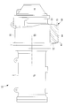
- the oil tank 50 of the compressor 3 ⁇ / b> C for a turbo refrigerator is erected upward from the bottom plate 51 and the outer peripheral edge portion of the bottom plate 51 (first A second side plate 52, a second side plate 53, a third side plate 54, and a fourth side plate (not shown);
- the bottom portion (lower portion) of the compressor casing 55 that constitutes the turbo refrigerator compressor 3C is formed.
- the bottom plate 51 is a plate-like member having a rectangular shape in a plan view extending along the axial direction and the left-right direction.
- the side plate 52 is a plate-like member which is located on the side of the (second) casing (in the present embodiment, the motor casing constituting the motor 2) 15 attached to one end of the casing 55 and extends along the vertical direction. is there.
- the side plate 53 is positioned on the side of the (third) casing (in the present embodiment, the compressor inlet casing forming the inlet of the compressor 3C for the turbo refrigerator) 16 attached to the other end of the casing 55 It is a plate-like member extending along the direction.
- the side plate 54 is a plate-like member which is located on one end side (the front side of the sheet of FIG. 3) of the bottom plate 51 and extends in the axial and vertical directions.
- the plate-like member has a rectangular shape in a plan view, which is located on the other end side (the rear side in the drawing of FIG. 3) of the bottom plate 51 and extends along the axial direction and the vertical direction.
- a band-like (sheet-like) heater 61 is provided on the outer surface of the bottom plate 51, the outer surface of the side plate 54, and the outer surface of the side plate (not shown). It is attached so that the surface and the outer surface of the side plate which is not shown in figure may be covered.
- a strip (sheet-like) metal having a large thermal conductivity (excellent in thermal conductivity) (For example, SUS430) is sandwiched in close contact with both sides.
- the oil tank 50 of the compressor 3C for a turbo refrigerator According to the oil tank 50 of the compressor 3C for a turbo refrigerator according to the present embodiment, that is, the oil tank 50 of the compressor 3C for a turbo refrigerator provided with the heater 61, replacement or inspection of the heater 61 can be performed by the bottom plate 51.
- the outer surface of the side plate 54, the outer surface of the side plate 54, and the heater 61 attached to the outer surface of the side plate (not shown) are simply removed.
- the heater 61 can be replaced or inspected without recovering the oil (not shown) present in the oil tank 50 and the refrigerant present in the turbo refrigerator 1C.
- the oil tank 50 of the compressor 3C for a turbo refrigerator according to the present embodiment, that is, according to the oil tank 50 of the compressor 3C for a turbo refrigerator provided with the heater 61, heat is generated between the heater 61 and the outer surface Since the sheet metal (not shown) having high conductivity is sandwiched between the two in close contact with each other, the heat transfer coefficient from the heater 61 to the outer surface of the oil tank 50 can be improved, and the output Small heaters can be employed.
- the heater 61 attached to the oil tank 50 is replaced without recovering the oil existing in the oil tank 50 and the refrigerant existing in the turbo refrigerator 1C. Or you can check. Further, according to the compressor 3C for a turbo refrigerator according to this embodiment, the heater 61 attached to the oil tank 50 without recovering the oil existing in the oil tank 50 and the refrigerant existing in the turbo refrigerator 1C. Since it is possible to replace or check the work time required to replace or check the heater 61, it is possible to greatly reduce the working rate and to improve its operation rate and reliability.
- the operation time required to replace or check the heater 61 attached to the oil tank 50 of the compressor 3C for the turbo refrigerator is significantly reduced, so the operation rate thereof And reliability can be improved.
- a compressor for a turbo refrigerator comprising an oil tank for a compressor for a turbo refrigerator according to a fourth embodiment of the present invention, and an oil tank for a compressor for a turbo refrigerator according to a fourth embodiment of the present invention
- a turbo refrigerator provided with a compressor for a turbo refrigerator according to a fourth embodiment of the present invention will be described with reference to FIG. As shown in FIG.
- the turbo refrigerator 1D is installed in a building or a factory, for example, to generate cooling water for air conditioning, and is rotationally driven by the motor 2 and is used as a refrigerant vapor Compressor for turbo refrigerator (Turbo type compressor) 3D which compresses to high pressure steam, an evaporator (not shown) which evaporates cold water, and a condenser which cools and condenses high pressure steam with cooling water ( And an expander (not shown) for decompressing and expanding the condensed refrigerant and sending it to the evaporator.
- the turbo refrigerator compressor 3D, the evaporator, the condenser, and the expander are connected by a refrigerant pipe (not shown) that circulates a refrigerant.
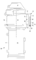
- the oil tank 70 of the compressor 3D for a turbo refrigerator is erected upward from the bottom plate 71 and the outer peripheral edge portion of the bottom plate 71 (first B) a side plate 72, a (second) side plate 73, a (third) side plate (not shown), and a (fourth) side plate (not shown);
- a bottom portion (lower portion) of the casing in the present embodiment, a compressor casing which constitutes the compressor 3D for a turbo refrigerator is formed.
- the bottom plate 71 is a plate-like member having a rectangular shape in a plan view extending along the axial direction and the left-right direction.
- the side plate 72 is a plate-like member extending along the vertical direction, located on the side of the (second) casing (in the present embodiment, the motor casing constituting the motor 2) 15 attached to one end of the casing 74 is there.
- the side plate 73 is positioned on the side of the (third) casing (in the present embodiment, the compressor inlet casing forming the inlet of the compressor 3D for the turbo refrigerator) 16 attached to the other end of the casing 74 It is a plate-like member extending along the direction.
- a hole 81 is provided extending along the axial direction towards.
- the hole 81 is positioned on the front side (the side of the casing 15) of the bottom plate 71 and receives the female screw portion of the screwed joint 83 provided at the base end of the rod-like (electric) heater (heating means) 82 1) the hole 84 and a (second) hole 85 through which the heater 82 is inserted at the back side of the bottom plate 71 (the back side of the hole 84).
- a male screw portion to be screwed with a female screw portion provided on the outer peripheral surface of the threaded joint 83 is provided on the inner peripheral surface of the hole 84.
- a heater 82 is inserted into the inside of the hole 81, and a heat transfer fluid having a large thermal conductivity (excellent in heat conduction) (for example, a heat-resistant heat-dissipating silicon material, a chemical) between the hole 81 and the heater 82 Synthetic oil, boron nitride aqueous solution) is filled.
- a plurality of (eight in the present embodiment) heat transfer fins 86 having a corrugated shape in cross section are provided on the upper surface (inner side surface) of the bottom plate 71.
- the heat transfer fins 86 are provided so as to project upward from the upper surface of the bottom plate 71, and the inner surface of a (third) side plate (not shown) along the vertical and horizontal directions. It extends continuously from the (inner surface) to the inner surface (inner surface) of the (fourth) side plate (not shown).
- symbol 87 in FIG. 4 has shown oil (lubricating oil).
- the oil tank 70 of the compressor 3D for a turbo refrigerator that is, the oil tank 70 of the compressor 3D for a turbo refrigerator provided with the heater 82, the upper surface of the bottom plate 71 protrudes upward. Since the plurality of heat transfer fins 86 are provided, the contact area between the bottom plate 71 heated by the heater 82 and the oil 87 can be increased, and the oil 86 can be warmed more efficiently. A heater with a small output can be adopted. The other operational effects are the same as those of the second embodiment described above, and thus the description thereof is omitted here.
- the present invention is not limited to the above-described embodiment, and may be modified or changed as needed.
- the heat transfer fluid having high thermal conductivity is filled between the protective tube 22 and the heater 26, but this heat transfer fluid is not essential.
- the heat transfer fluid having high thermal conductivity is filled between the hole 41 and the heater 42, but this heat transfer fluid is not essential.
- the outer surface of the bottom plate 51, the outer surface of the side plate 54, and the outer surface of the side plate (not shown) and the heater 61 both adhere to each other.
- a band of metal is inserted, but this metal is not essential.
- one specific example is one in which the heater 61 is attached so as to cover the outer surface of the bottom plate 51, the outer surface of the side plate 54, and the outer surface of the side plate not shown.
- the present invention is not limited to this, and the heater may be attached so as to cover only the outer surface of the bottom plate 51.
- the temperature of the oil is measured because the bottom plate and the side plate may become hot. It is more preferable to provide a (second) thermometer for measuring the temperature of the oil tank, monitor both the temperature of the oil and the temperature of the oil tank, and turn the heater on and off. Thereby, it is possible to prevent the temperature of the oil tank that may be touched by human hands from being excessively heated, and to improve the safety.
- the entire outer side of the oil tank in the first embodiment, the second embodiment and the fourth embodiment, and the entire outer side of the oil tank and the heater in the third embodiment be covered with a heat insulating material. .
- the heat radiation amount can be reduced to improve the heat retention, the power consumption of the heater can be reduced, and the running cost can be reduced.
- the heaters 42 and 82 are configured by four heaters (total 2000 W) having a capacity of 500 W.
- the temperature of the oil tanks 30, 70 is 30 ° C. or less, all four are used to heat the oil tanks 30, 70, and the temperature of the oil tanks 30, 70 is higher than 30 ° C. and higher than 50 ° C.
- the oil tank 30, 70 is heated using three of the four when the oil temperature is too low, and when the temperature of the oil tank 30, 70 is 50 ° C. or more, the oil is used using two of the four.
- the tanks 30, 70 can be heated. That is, under the condition that the temperature of the oil tanks 30, 70 has ample time for heating the oil, the amount of heating from the heaters 42, 82 to the oil tanks 30, 70 can be reduced, and release to the ambient atmosphere. The amount of heat can be reduced.
Landscapes
- Engineering & Computer Science (AREA)
- Mechanical Engineering (AREA)
- General Engineering & Computer Science (AREA)
- Physics & Mathematics (AREA)
- Thermal Sciences (AREA)
- Structures Of Non-Positive Displacement Pumps (AREA)
- Compressor (AREA)
Abstract
Description
本発明の第1の態様は、底面板と、該底面板の外周縁部から上方に向かって立設された側面板と、を備え、ターボ冷凍機用圧縮機を構成するケーシングの底部を形成するターボ冷凍機用圧縮機のオイルタンクであって、前記側面板には、板厚方向に貫通する貫通穴が設けられており、この貫通穴内には、先端が閉塞端とされた保護管が挿通されているとともに、この保護管内には、当該保護管に対して抜き差し可能に構成された棒状のヒーターが挿通されている。
これにより、オイルタンク内に存するオイル、およびターボ冷凍機内に存する冷媒を回収することなくヒーターを交換または点検することができる。
これにより、オイルタンク内に存するオイル、およびターボ冷凍機内に存する冷媒を回収することなくヒーターを交換または点検することができる。
これにより、オイルタンク内に存するオイル、およびターボ冷凍機内に存する冷媒を回収することなくヒーターを交換または点検することができる。
また、この構成によれば、オイルタンク内に存するオイル、およびターボ冷凍機内に存する冷媒を回収することなく、オイルタンクに取り付けられたヒーターを交換または点検することができるので、ヒーターの交換または点検に要する作業時間を大幅に低減させることができ、その稼働率および信頼性を向上させることができる。
以下、本発明の第1実施形態に係るターボ冷凍機用圧縮機のオイルタンク、および本発明の第1実施形態に係るターボ冷凍機用圧縮機のオイルタンクを備えたターボ冷凍機用圧縮機、ならびに本発明の第1実施形態に係るターボ冷凍機用圧縮機を備えたターボ冷凍機について、図1を用いて説明する。
図1に示すように、本実施形態に係るターボ冷凍機1Aは、例えば、空気調節用の冷却水を生成するためにビルディングや工場に設置されるものであり、電動機2によって回転駆動され冷媒蒸気を圧縮して高圧蒸気にするターボ冷凍機用圧縮機(ターボ形圧縮機)3Aと、冷水を蒸発させる蒸発器(図示せず)と、高圧蒸気を冷却水で冷却して凝縮させる凝縮器(図示せず)と、凝縮した冷媒を減圧して膨張させて蒸発器に送る膨張機(図示せず)と、を備えている。ターボ冷凍機用圧縮機3A、蒸発器、凝縮器、および膨張機は、冷媒を循環させる冷媒配管(図示せず)によって連結されている。
側面板12は、ケーシング14の一端に取り付けられる(第2の)ケーシング(本実施形態では、電動機2を構成するモータケーシング)15の側に位置して上下方向に沿って延びる板状の部材である。
側面板13は、ケーシング14の他端に取り付けられる(第3の)ケーシング(本実施形態では、ターボ冷凍機用圧縮機3Aの入口を形成する圧縮機入口ケーシング)16の側に位置して上下方向に沿って延びる板状の部材である。
貫通穴21は、側面板12の手前側(外側)に位置して、保護管22の基端部に設けられたねじ込み継手23の雌ねじ部を受け入れる(第1の)貫通穴24と、側面板12の奥側(内側)に位置して、保護管22が挿通される(第2の)貫通穴25と、を備えている。
保護管22の内部には、ヒーター26が挿通されており、保護管22とヒーター26との間には、熱伝導率の大きい(熱伝導に優れた)伝熱流体(例えば、耐熱放熱シリコン材、化学合成油、窒化ホウ素水溶液)が充填されている。
なお、図1中の符号27はオイル(潤滑油)を示している。
これにより、オイルタンク10内に存するオイル27、およびターボ冷凍機1A内に存する冷媒を回収することなくヒーター26を交換または点検することができる。
また、本実施形態に係るターボ冷凍機用圧縮機3Aによれば、オイルタンク10内に存するオイル27、およびターボ冷凍機1A内に存する冷媒を回収することなく、オイルタンク10に取り付けられたヒーター26を交換または点検することができるので、ヒーター26の交換または点検に要する作業時間を大幅に低減させることができ、その稼働率および信頼性を向上させることができる。
本発明の第2実施形態に係るターボ冷凍機用圧縮機のオイルタンク、および本発明の第2実施形態に係るターボ冷凍機用圧縮機のオイルタンクを備えたターボ冷凍機用圧縮機、ならびに本発明の第2実施形態に係るターボ冷凍機用圧縮機を備えたターボ冷凍機について、図2を用いて説明する。
図2に示すように、本実施形態に係るターボ冷凍機1Bは、例えば、空気調節用の冷却水を生成するためにビルディングや工場に設置されるものであり、電動機2によって回転駆動され冷媒蒸気を圧縮して高圧蒸気にするターボ冷凍機用圧縮機(ターボ形圧縮機)3Bと、冷水を蒸発させる蒸発器(図示せず)と、高圧蒸気を冷却水で冷却して凝縮させる凝縮器(図示せず)と、凝縮した冷媒を減圧して膨張させて蒸発器に送る膨張機(図示せず)と、を備えている。ターボ冷凍機用圧縮機3B、蒸発器、凝縮器、および膨張機は、冷媒を循環させる冷媒配管(図示せず)によって連結されている。
側面板32は、ケーシング34の一端に取り付けられる(第2の)ケーシング(本実施形態では、電動機2を構成するモータケーシング)15の側に位置して上下方向に沿って延びる板状の部材である。
側面板33は、ケーシング34の他端に取り付けられる(第3の)ケーシング(本実施形態では、ターボ形圧縮機3Bの入口を形成する圧縮機入口ケーシング)16の側に位置して上下方向に沿って延びる板状の部材である。
穴41は、底面板31の手前側(ケーシング15の側)に位置して、棒状の(電気)ヒーター(加熱手段)42の基端部に設けられたねじ込み継手43の雌ねじ部を受け入れる(第1の)穴44と、底面板31の奥側(穴44の奥側)に位置して、ヒーター42が挿通される(第2の)穴45と、を備えている。
穴41の内部には、ヒーター42が挿通されており、穴41とヒーター42との間には、熱伝導率の大きい(熱伝導に優れた)伝熱流体(例えば、耐熱放熱シリコン材、化学合成油、窒化ホウ素水溶液)が充填されている。
なお、図2中の符号46はオイル(潤滑油)を示している。
これにより、オイルタンク30内に存するオイル46、およびターボ冷凍機1B内に存する冷媒を回収することなくヒーター42を交換または点検することができる。
また、本実施形態に係るターボ冷凍機用圧縮機3Bによれば、オイルタンク30内に存するオイル46、およびターボ冷凍機1B内に存する冷媒を回収することなく、オイルタンク30に取り付けられたヒーター42を交換または点検することができるので、ヒーター42の交換または点検に要する作業時間を大幅に低減させることができ、その稼働率および信頼性を向上させることができる。
本発明の第3実施形態に係るターボ冷凍機用圧縮機のオイルタンク、および本発明の第3実施形態に係るターボ冷凍機用圧縮機のオイルタンクを備えたターボ冷凍機用圧縮機、ならびに本発明の第3実施形態に係るターボ冷凍機用圧縮機を備えたターボ冷凍機について、図3を用いて説明する。
図3に示すように、本実施形態に係るターボ冷凍機1Cは、例えば、空気調節用の冷却水を生成するためにビルディングや工場に設置されるものであり、電動機2によって回転駆動され冷媒蒸気を圧縮して高圧蒸気にするターボ冷凍機用圧縮機(ターボ形圧縮機)3Cと、冷水を蒸発させる蒸発器(図示せず)と、高圧蒸気を冷却水で冷却して凝縮させる凝縮器(図示せず)と、凝縮した冷媒を減圧して膨張させて蒸発器に送る膨張機(図示せず)と、を備えている。ターボ冷凍機用圧縮機3C、蒸発器、凝縮器、および膨張機は、冷媒を循環させる冷媒配管(図示せず)によって連結されている。
側面板52は、ケーシング55の一端に取り付けられる(第2の)ケーシング(本実施形態では、電動機2を構成するモータケーシング)15の側に位置して上下方向に沿って延びる板状の部材である。
側面板53は、ケーシング55の他端に取り付けられる(第3の)ケーシング(本実施形態では、ターボ冷凍機用圧縮機3Cの入口を形成する圧縮機入口ケーシング)16の側に位置して上下方向に沿って延びる板状の部材である。
これにより、オイルタンク50内に存するオイル(図示せず)、およびターボ冷凍機1C内に存する冷媒を回収することなくヒーター61を交換または点検することができる。
また、本実施形態に係るターボ冷凍機用圧縮機3Cによれば、オイルタンク50内に存するオイル、およびターボ冷凍機1C内に存する冷媒を回収することなく、オイルタンク50に取り付けられたヒーター61を交換または点検することができるので、ヒーター61の交換または点検に要する作業時間を大幅に低減させることができ、その稼働率および信頼性を向上させることができる。
本発明の第4実施形態に係るターボ冷凍機用圧縮機のオイルタンク、および本発明の第4実施形態に係るターボ冷凍機用圧縮機のオイルタンクを備えたターボ冷凍機用圧縮機、ならびに本発明の第4実施形態に係るターボ冷凍機用圧縮機を備えたターボ冷凍機について、図4を用いて説明する。
図4に示すように、本実施形態に係るターボ冷凍機1Dは、例えば、空気調節用の冷却水を生成するためにビルディングや工場に設置されるものであり、電動機2によって回転駆動され冷媒蒸気を圧縮して高圧蒸気にするターボ冷凍機用圧縮機(ターボ形圧縮機)3Dと、冷水を蒸発させる蒸発器(図示せず)と、高圧蒸気を冷却水で冷却して凝縮させる凝縮器(図示せず)と、凝縮した冷媒を減圧して膨張させて蒸発器に送る膨張機(図示せず)と、を備えている。ターボ冷凍機用圧縮機3D、蒸発器、凝縮器、および膨張機は、冷媒を循環させる冷媒配管(図示せず)によって連結されている。
側面板72は、ケーシング74の一端に取り付けられる(第2の)ケーシング(本実施形態では、電動機2を構成するモータケーシング)15の側に位置して上下方向に沿って延びる板状の部材である。
側面板73は、ケーシング74の他端に取り付けられる(第3の)ケーシング(本実施形態では、ターボ冷凍機用圧縮機3Dの入口を形成する圧縮機入口ケーシング)16の側に位置して上下方向に沿って延びる板状の部材である。
穴81は、底面板71の手前側(ケーシング15の側)に位置して、棒状の(電気)ヒーター(加熱手段)82の基端部に設けられたねじ込み継手83の雌ねじ部を受け入れる(第1の)穴84と、底面板71の奥側(穴84の奥側)に位置して、ヒーター82が挿通される(第2の)穴85と、を備えている。
穴81の内部には、ヒーター82が挿通されており、穴81とヒーター82との間には、熱伝導率の大きい(熱伝導に優れた)伝熱流体(例えば、耐熱放熱シリコン材、化学合成油、窒化ホウ素水溶液)が充填されている。
なお、図4中の符号87はオイル(潤滑油)を示している。
その他の作用効果は、上述した第2実施形態のものと同じであるので、ここではその説明を省略する。
例えば、上述した第1実施形態では、保護管22とヒーター26との間に、熱伝導率の大きい伝熱流体を充填するようにしたが、この伝熱流体は、必須のものではない。
これにより、人の手が触れるおそれのあるオイルタンクの温度が過度に熱くなるのを防止することができ、安全性を向上させることができる。
これにより、放熱量を低減させて保温性を高めることができ、ヒーターの消費電力を低減させることができて、ランニングコストを低減させることができる。
これにより、例えば、オイルタンク30,70の温度が30℃以下のときには、4本全部を使用してオイルタンク30,70を加熱し、オイルタンク30,70の温度が30℃より高く50℃よりも低いときには、4本のうちの3本を使用してオイルタンク30,70を加熱し、オイルタンク30,70の温度が50℃以上のときには、4本のうちの2本を使用してオイルタンク30,70を加熱することができる。
すなわち、オイルの加熱時間に余裕のある、オイルタンク30,70の温度が高い条件では、ヒーター42,82からオイルタンク30,70への加熱量を小さくすることができて、周囲雰囲気への放熱量を小さくすることができる。
1B ターボ冷凍機
1C ターボ冷凍機
1D ターボ冷凍機
3A ターボ冷凍機用圧縮機
3B ターボ冷凍機用圧縮機
3C ターボ冷凍機用圧縮機
3D ターボ冷凍機用圧縮機
10 オイルタンク
11 底面板
12 側面板
13 側面板
14 ケーシング
21 貫通穴
22 保護管
26 ヒーター
30 オイルタンク
31 底面板
32 側面板
33 側面板
34 ケーシング
41 穴
42 ヒーター
50 オイルタンク
51 底面板
52 側面板
53 側面板
54 側面板
55 ケーシング
61 ヒーター
70 オイルタンク
71 底面板
72 側面板
73 側面板
74 ケーシング
81 穴
82 ヒーター
Claims (10)
- 底面板と、該底面板の外周縁部から上方に向かって立設された側面板と、を備え、ターボ冷凍機用圧縮機を構成するケーシングの底部を形成するターボ冷凍機用圧縮機のオイルタンクであって、
前記側面板には、板厚方向に貫通する貫通穴が設けられており、この貫通穴内には、先端が閉塞端とされた保護管が挿通されているとともに、この保護管内には、当該保護管に対して抜き差し可能に構成された棒状のヒーターが挿通されているターボ冷凍機用圧縮機のオイルタンク。 - 前記貫通穴が、前記側面板の最低部に設けられている請求項1に記載のターボ冷凍機用圧縮機のオイルタンク。
- 前記保護管と前記ヒーターとの間に、熱伝導率の大きい伝熱流体が充填されている請求項1または2に記載のターボ冷凍機用圧縮機のオイルタンク。
- 底面板と、該底面板の外周縁部から上方に向かって立設された側面板と、を備え、ターボ冷凍機用圧縮機を構成するケーシングの底部を形成するターボ冷凍機用圧縮機のオイルタンクであって、
前記底面板の内部には、当該底面板の一端面から、該一端面の反対側に位置する他端面に向かって延びる穴が設けられており、この穴内には、当該穴に対して抜き差し可能に構成された棒状のヒーターが挿通されているターボ冷凍機用圧縮機のオイルタンク。 - 前記穴と前記ヒーターとの間に、熱伝導率の大きい伝熱流体が充填されている請求項4に記載のターボ冷凍機用圧縮機のオイルタンク。
- 底面板と、該底面板の外周縁部から上方に向かって立設された側面板と、を備え、ターボ冷凍機用圧縮機を構成するケーシングの底部を形成するターボ冷凍機用圧縮機のオイルタンクであって、
前記底面板の外表面、または、前記底面板の外表面および前記側面板の外表面には、シート状のヒーターが、前記外表面を覆うようにして取り付けられているターボ冷凍機用圧縮機のオイルタンク。 - 前記ヒーターと前記外表面との間に、熱伝導率の大きいシート状の金属が双方に密着するようにして挟み込まれている請求項6に記載のターボ冷凍機用圧縮機のオイルタンク。
- 前記底面板の上面から上方に向かって突出する複数枚の伝熱フィンが設けられている請求項4から7のいずれか一項に記載のターボ冷凍機用圧縮機のオイルタンク。
- 請求項1から8のいずれか一項に記載のターボ冷凍機用圧縮機のオイルタンクを備えているターボ冷凍機用圧縮機。
- 請求項9に記載のターボ冷凍機用圧縮機を備えているターボ冷凍機。
Priority Applications (5)
| Application Number | Priority Date | Filing Date | Title |
|---|---|---|---|
| MYPI2015702725A MY183372A (en) | 2013-03-06 | 2014-02-13 | Oil tank of turbo chiller compressor and turbo chiller compressor |
| SG11201506716YA SG11201506716YA (en) | 2013-03-06 | 2014-02-13 | Oil tank of turbo chiller compressor and turbo chiller compressor |
| US14/768,326 US9856885B2 (en) | 2013-03-06 | 2014-02-13 | Oil tank of turbo chiller compressor and turbo chiller compressor |
| CN201480010246.5A CN105026770A (zh) | 2013-03-06 | 2014-02-13 | 涡轮制冷机用压缩机的油箱以及涡轮制冷机用压缩机 |
| DE112014001139.8T DE112014001139T5 (de) | 2013-03-06 | 2014-02-13 | Öltank eines Turbokältekompressors und Turbokältekompressor |
Applications Claiming Priority (2)
| Application Number | Priority Date | Filing Date | Title |
|---|---|---|---|
| JP2013044010A JP6223696B2 (ja) | 2013-03-06 | 2013-03-06 | ターボ冷凍機用圧縮機のオイルタンクおよびターボ冷凍機用圧縮機 |
| JP2013-044010 | 2013-03-06 |
Publications (1)
| Publication Number | Publication Date |
|---|---|
| WO2014136540A1 true WO2014136540A1 (ja) | 2014-09-12 |
Family
ID=51491065
Family Applications (1)
| Application Number | Title | Priority Date | Filing Date |
|---|---|---|---|
| PCT/JP2014/053255 Ceased WO2014136540A1 (ja) | 2013-03-06 | 2014-02-13 | ターボ冷凍機用圧縮機のオイルタンクおよびターボ冷凍機用圧縮機 |
Country Status (7)
| Country | Link |
|---|---|
| US (1) | US9856885B2 (ja) |
| JP (1) | JP6223696B2 (ja) |
| CN (2) | CN110307176A (ja) |
| DE (1) | DE112014001139T5 (ja) |
| MY (1) | MY183372A (ja) |
| SG (1) | SG11201506716YA (ja) |
| WO (1) | WO2014136540A1 (ja) |
Families Citing this family (4)
| Publication number | Priority date | Publication date | Assignee | Title |
|---|---|---|---|---|
| JP2018169059A (ja) * | 2017-03-29 | 2018-11-01 | 三菱重工サーマルシステムズ株式会社 | 冷凍機 |
| CN107218711B (zh) * | 2017-07-31 | 2019-11-08 | 青岛海信日立空调系统有限公司 | 一种空调器及其控制方法 |
| DE102020117899B4 (de) | 2020-07-07 | 2022-11-17 | SPH Sustainable Process Heat GmbH | Hochtemperaturwärmepumpe |
| CN114645876A (zh) * | 2022-03-24 | 2022-06-21 | 诺文科智能通风研究院(西安)有限公司 | 具有限制性消音结构的低噪音通风机及其方法 |
Citations (4)
| Publication number | Priority date | Publication date | Assignee | Title |
|---|---|---|---|---|
| JPS57170296U (ja) * | 1981-04-22 | 1982-10-26 | ||
| JPS59187798U (ja) * | 1983-06-01 | 1984-12-13 | 株式会社日立製作所 | ほう酸水貯蔵タンクの構造 |
| JP2000230494A (ja) * | 1999-02-08 | 2000-08-22 | Asahi Kogyo Kk | 温暖液体循環装置 |
| JP2011026958A (ja) * | 2009-07-21 | 2011-02-10 | Ihi Corp | ターボ圧縮機及び冷凍機 |
Family Cites Families (11)
| Publication number | Priority date | Publication date | Assignee | Title |
|---|---|---|---|---|
| US2175913A (en) * | 1935-12-18 | 1939-10-10 | Nash Kelvinator Corp | Motor-compressor unit for refrigerating apparatus |
| US3251537A (en) * | 1961-03-10 | 1966-05-17 | Cons Vacuum Corp | Heater for a diffusion pump |
| US3235032A (en) * | 1963-05-16 | 1966-02-15 | Charles L Lovercheck | Means for heating the oil sump of an engine |
| US4066869A (en) * | 1974-12-06 | 1978-01-03 | Carrier Corporation | Compressor lubricating oil heater control |
| JPH0442560Y2 (ja) | 1985-04-02 | 1992-10-07 | ||
| JPS6296791A (ja) * | 1985-10-23 | 1987-05-06 | Mitsubishi Electric Corp | 冷媒圧縮機 |
| US4755657A (en) * | 1986-12-16 | 1988-07-05 | American Standard Inc. | Method of heating an oil reservoir of a refrigeration compressor |
| AU5465699A (en) * | 1998-09-22 | 2000-04-10 | American Standard, Inc. | Refrigeration apparatus including an oil sump heater |
| US7059839B2 (en) * | 2002-12-10 | 2006-06-13 | Tecumseh Products Company | Horizontal compressor end cap with a terminal, a visually transparent member, and a heater well mounted on the end cap projection |
| CN2681008Y (zh) * | 2004-01-02 | 2005-02-23 | 北京斯达宝电器有限公司 | 利用低谷电能的贮热式房间加热器 |
| CN201137571Y (zh) | 2007-11-13 | 2008-10-22 | 擎宇国际股份有限公司 | 涡卷式压缩机密封嵌入式加热结构 |
-
2013
- 2013-03-06 JP JP2013044010A patent/JP6223696B2/ja active Active
-
2014
- 2014-02-13 SG SG11201506716YA patent/SG11201506716YA/en unknown
- 2014-02-13 MY MYPI2015702725A patent/MY183372A/en unknown
- 2014-02-13 CN CN201910547248.2A patent/CN110307176A/zh active Pending
- 2014-02-13 CN CN201480010246.5A patent/CN105026770A/zh active Pending
- 2014-02-13 US US14/768,326 patent/US9856885B2/en active Active
- 2014-02-13 WO PCT/JP2014/053255 patent/WO2014136540A1/ja not_active Ceased
- 2014-02-13 DE DE112014001139.8T patent/DE112014001139T5/de not_active Withdrawn
Patent Citations (4)
| Publication number | Priority date | Publication date | Assignee | Title |
|---|---|---|---|---|
| JPS57170296U (ja) * | 1981-04-22 | 1982-10-26 | ||
| JPS59187798U (ja) * | 1983-06-01 | 1984-12-13 | 株式会社日立製作所 | ほう酸水貯蔵タンクの構造 |
| JP2000230494A (ja) * | 1999-02-08 | 2000-08-22 | Asahi Kogyo Kk | 温暖液体循環装置 |
| JP2011026958A (ja) * | 2009-07-21 | 2011-02-10 | Ihi Corp | ターボ圧縮機及び冷凍機 |
Also Published As
| Publication number | Publication date |
|---|---|
| US9856885B2 (en) | 2018-01-02 |
| DE112014001139T5 (de) | 2015-11-19 |
| SG11201506716YA (en) | 2015-09-29 |
| CN105026770A (zh) | 2015-11-04 |
| JP6223696B2 (ja) | 2017-11-01 |
| JP2014173435A (ja) | 2014-09-22 |
| CN110307176A (zh) | 2019-10-08 |
| US20160010654A1 (en) | 2016-01-14 |
| MY183372A (en) | 2021-02-18 |
Similar Documents
| Publication | Publication Date | Title |
|---|---|---|
| CN104654669B (zh) | 换热装置及具有其的半导体制冷冰箱 | |
| EP3220081B1 (en) | Semiconductor refrigerator | |
| EP3220080B1 (en) | Cold end heat exchanging device and semiconductor refrigerator | |
| JP6223696B2 (ja) | ターボ冷凍機用圧縮機のオイルタンクおよびターボ冷凍機用圧縮機 | |
| CN104967007A (zh) | 一种用于环网柜封闭空间的除湿装置 | |
| BR112012020769A2 (pt) | aparelho para resfriamento, e, uso de um aparelho | |
| WO2013012270A3 (ko) | 응축기가 증발기 하부 또는 측부에 위치하는 저온비등 냉각시스템 | |
| KR20110104141A (ko) | 방사형(격자구조)의 주름을 갖는 이중관 냉동시스템 열교환기 | |
| JP2014173435A5 (ja) | ||
| CN102128517A (zh) | 冷热交换装置 | |
| CN102022864B (zh) | 用于对有机朗肯循环蒸发器传递热量的热管 | |
| CA2692229A1 (en) | Thermoeletric 2-phase gravity condenser & methods of improving existing heat pipe systems | |
| EP4033159B1 (en) | Thermotechnical system and method for high efficiency heat transfer and distribution | |
| KR101788095B1 (ko) | 냉각기용 열교환기의 성에제거 장치 | |
| CN104034191B (zh) | 利用冰箱余热的热水器 | |
| CN209857249U (zh) | 散热装置及具有其的空调器 | |
| Prasonna et al. | Enhancement of COP in a Vapour Compression Refrigeration System | |
| CN104242069A (zh) | 一种电气箱除湿装置 | |
| CN106152607A (zh) | 空气能热泵 | |
| CN204680927U (zh) | 用于环网柜封闭空间的除湿装置 | |
| WO2012085551A3 (en) | Method & apparatus for the improvement of efficiency of thermal cycles | |
| JP6152661B2 (ja) | 蒸気発生システム | |
| RU132879U1 (ru) | Рекуперативный теплообменник холодильной установки | |
| AU2011100888A4 (en) | A Solar Air Conditioning System | |
| CN202216401U (zh) | 一种无风机强制对流直接蒸发膨胀式空气源热泵热水器 |
Legal Events
| Date | Code | Title | Description |
|---|---|---|---|
| WWE | Wipo information: entry into national phase |
Ref document number: 201480010246.5 Country of ref document: CN |
|
| 121 | Ep: the epo has been informed by wipo that ep was designated in this application |
Ref document number: 14760658 Country of ref document: EP Kind code of ref document: A1 |
|
| WWE | Wipo information: entry into national phase |
Ref document number: 14768326 Country of ref document: US |
|
| WWE | Wipo information: entry into national phase |
Ref document number: 1120140011398 Country of ref document: DE Ref document number: 112014001139 Country of ref document: DE |
|
| 122 | Ep: pct application non-entry in european phase |
Ref document number: 14760658 Country of ref document: EP Kind code of ref document: A1 |