WO2014136475A1 - パルスパワーによる中子砂処理装置 - Google Patents
パルスパワーによる中子砂処理装置 Download PDFInfo
- Publication number
- WO2014136475A1 WO2014136475A1 PCT/JP2014/050570 JP2014050570W WO2014136475A1 WO 2014136475 A1 WO2014136475 A1 WO 2014136475A1 JP 2014050570 W JP2014050570 W JP 2014050570W WO 2014136475 A1 WO2014136475 A1 WO 2014136475A1
- Authority
- WO
- WIPO (PCT)
- Prior art keywords
- casting
- core
- discharge
- core sand
- electrode
- Prior art date
- Legal status (The legal status is an assumption and is not a legal conclusion. Google has not performed a legal analysis and makes no representation as to the accuracy of the status listed.)
- Ceased
Links
Images



Classifications
-
- B—PERFORMING OPERATIONS; TRANSPORTING
- B22—CASTING; POWDER METALLURGY
- B22D—CASTING OF METALS; CASTING OF OTHER SUBSTANCES BY THE SAME PROCESSES OR DEVICES
- B22D29/00—Removing castings from moulds, not restricted to casting processes covered by a single main group; Removing cores; Handling ingots
- B22D29/001—Removing cores
- B22D29/007—Removing cores by using explosive shock waves
Definitions
- the present invention relates to a core sand treatment apparatus that collapses core sand in a cast product by using pulse power (instant discharge of accumulated electric energy).
- Patent Documents 1 to 3 propose proposals for removing it by collapsing with pulse power.
- Patent Document 1 a spark is generated by applying a high voltage to a liquid in which a casting is immersed, and the bound state of the core is loosened by the shock wave of the spark and the casting is moved in a reciprocating stroke. It is described that the core sand remaining in the area can be efficiently removed.
- Patent Document 2 as a core sand dropping device that crushes a core in a casting with a shock wave generated by underwater discharge, a cage that can be raised and lowered is provided in a water tank, and the casting is accommodated in the cage and provided above the cage.
- a structure in which a discharge electrode is attached to a traveling carriage is disclosed.
- Patent Document 3 proposes a method for crushing rocks and concrete by continuously drilling a plurality of holes in rocks and concrete, inserting electrode rods into these holes, and sequentially discharging them. Has been.
- Patent Documents 1 to 3 the entire processing apparatus (machine frame) is grounded without providing any electrode in contact with the casting. Since Patent Document 3 is rock or concrete, there is no worry of electric shock. However, in Patent Documents 1 and 2, since the machine frame of the device is grounded, it is conceivable that the ground may come off at the mass production site. It is dangerous to touch the machine frame during discharge.
- Patent Documents 1 and 2 no consideration is given to which part of the casting the shock wave is directed to. For this reason, melt damage may occur in places that should not be damaged. In Patent Document 3, there is no description of discharge itself.
- Patent Documents 1 and 2 discharge is performed in a liquid in order to reduce a loud sound generated at the time of discharge.
- Patent Document 3 there is no description of soundproofing or soundproofing measures.
- the discharge sound generated at the time of discharge is a soaring sound like a lightning strike, effective soundproofing and soundproofing measures are required at the work site.
- the core sand treatment apparatus using pulse power includes a pair of electrodes for discharging the casting in the water tank and is discharged into the casting by being discharged in water. This is a device that destroys and drops the core.
- One electrode of the set of electrodes may be a casting itself, and the remaining electrodes form a slight gap with the casting and the tip is directed to the casting.
- the tip of the electrode provided with the gap is pointed (including a rounded shape), and by making it sharp, discharge becomes easy, and at the same time, discharge aimed at a specific position such as a casting gate can be performed.
- the tip of the other electrode can be grounded reliably by making it flat.
- both the electrodes are biased downward by a spring in order to alleviate the impact received during discharge.
- the inner surface and the outer surface are made of stainless steel plates, and a vibration absorbing layer (for example, butyl rubber) and a sound absorbing layer (for example, soft urethane) are provided between the inner surface and the outer surface.
- a vibration absorbing layer for example, butyl rubber
- a sound absorbing layer for example, soft urethane
- a shock wave is directly transmitted to the casting through a slight gap between the tip of one of the electrodes for discharge and the casting. Therefore, the core sand remaining inside the casting can be efficiently destroyed and dropped off.
- melting damage may occur at the discharge portion of the casting, there is no adverse effect on the product if the electrode is directed to the portion to be machined in the subsequent process.
- one of the electrodes for discharge or the entire casting itself was grounded and an independent circuit was isolated from the machine frame from the discharge part to the ground, so it was in contact with the machine frame of the water tank during the discharge. It is safe as well. The same applies when the other electrode is the casting itself.
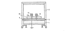
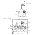
- FIG. 1 shows a state after the set base is fixed in the water tank
- FIG. 3 shows a state before the set base is fixed in the water tank.
- reference numeral 1 denotes a mounting table
- a water tank 3 is installed on the mounting table 1 via an insulator 2 such as rubber.
- the shock wave is larger as the viscosity is higher, such as oil, but pure water is preferable in view of post-treatment.
- it is not necessary to install the mounting table 1, but it is preferable to install it for safety as shown in the illustrated example.
- the structure of the water tank 3 is a discharge sound antireflection plate 4 made of stainless steel or the like on the inner surface in contact with water, and a vibration absorbing layer 5 such as butyl rubber is provided outside the discharge sound antireflection plate 4.
- a sound absorbing layer 6 such as soft urethane is provided on the outside of the vibration absorbing layer 5, and the outermost side is a sound insulating plate 7 such as stainless steel.
- a pump 8 that generates a water flow in the water in the water tank 3 is disposed outside the water tank 3, and it is desirable to discharge the crushed core in the casting from the bottom of the water tank (not shown) by the water flow.
- a receiving seat 9 is fixed on the inner bottom surface of the water tank 3, and a positioning member 10 made of an insulator is fixed on the receiving seat 9 with an insulating bolt (not shown).
- a concave portion 10a into which the set base 11 is fitted is formed on the inner periphery of the positioning member 10 so as to stand upright.
- a lock member 12 is arranged around the seat 9.
- the lock member 12 includes a pressing piece 13 that is pressed from above in a state in which the set base 11 is fitted in the recess 10a of the positioning member 10, and the lower surface of the pressing piece 13 is formed of an insulator 13a.
- the set table 11 is made of metal and has a lower plate 14.
- the lower plate 14 is for positioning and fixing the casting W, and the surface to be fixed is the uneven portion 14a, so that the reflection of the shock wave of the pulse power can be used effectively.
- Supports 15 are erected from the four corners of the lower plate 14, and an upper plate 16 is attached to the upper ends of these supports 15.
- a pair of electrodes 17 (low potential side) and electrodes 18 (high potential) are attached to the upper plate 16. Side) is attached. Note that the low potential and the high potential setting may be reversed.
- a rail 19 is disposed above the water tank 3, and a self-propelled vehicle 20 is attached to the rail 19, so that the set table 11 can be conveyed.
- the electrode during conveyance may be left connected even if a conducting wire (cable) is removed.
- the electrode 17 has a discharge portion 21 at the lower end, and the tip of the discharge portion 21 is rounded and pointed. Therefore, it is easy to discharge and it is easy to control the direction of discharge.
- the electrode 18 includes a power receiving unit 22 at the lower end, and the lower surface of the power receiving unit 22 is a flat surface. Therefore, the casting W can be reliably grounded.
- the electrode 17 and the electrode 18 are attached to the upper plate 16 with the discharge portion 21 and the power receiving portion 22 biased downward via springs 23 and 24, respectively.
- the spring 23 is for reducing the impact when the electrode 17 is discharged, and is essential on the electrode 17 side.
- the water tank 3 is filled with water as a soundproofing liquid.
- the water is preferably pure water, but is not limited thereto.
- the water level is set to be higher than the casting W set on the setting table 11.
- the casting W is set on the setting table 11. At this time, as shown in FIG.
- the discharge part 21 of the electrode 17 is opposed to the casting W through a gap, and the power receiving part 22 of the electrode 18 is brought into contact with the casting W.
- the size of the gap is suitably 3 to 7 mm in order to generate an efficient shock wave.
- a conductive wire 25 connected to the pulse power generator is connected to the electrode 17, and a grounding conductive wire 26 is connected to the electrode 18 to generate pulse power.
- a spark 27 is generated between the discharge portion 21 of the electrode 17 and the casting W, a shock wave is transmitted to the core 28 in the casting W, the core 28 is collapsed, and the pump The water constituting the core 28 is discharged into the water in the water tank 3 by the water flow generated from the water.
- the core power processing apparatus using pulse power according to the present invention is not limited to an automobile engine, and can be widely used as an apparatus for removing core sand from a casting using a sand core.
Landscapes
- Engineering & Computer Science (AREA)
- Mechanical Engineering (AREA)
- Disintegrating Or Milling (AREA)
- Electrical Discharge Machining, Electrochemical Machining, And Combined Machining (AREA)
Abstract
【課題】 安全でしかも効率のよいパルスパワーによる中子砂処理装置を提供する。 【解決手段】 鋳物Wと正電極17の放電部21をギャップを介して対向させ、また負電極18の受電部22を鋳物Wに接触させる。次いで、正電極17にはパルスパワー発生部につながる導線25を接続し、負電極18には接地用の導線26を接続し、正電極17に高電圧を印加する。正電極17の放電部21と鋳物Wとの間でスパーク27が発生し、衝撃波が鋳物W内の中子28に伝達され、中子28が崩壊し、中子28を構成していた砂が水槽3内の水中に放出される。
Description
本発明は、パルスパワー(蓄積した電気エネルギーの瞬時放電)を利用して鋳造品内の中子砂を崩壊させる中子砂処理装置に関する。
鋳造工程後のエンジン等の鋳物内に鋳込まれて固まっている中子は除去し難い場合があり、これをパルスパワーで崩壊させて除去する提案が特許文献1~3になされている。
特許文献1には、鋳物を浸漬させた液体に高電圧を印加してスパークを発生させ、このスパークの衝撃波によって中子の結着状態を緩めると共に鋳物を往復ストローク動せしめることで、鋳物の内部に留まっている中子砂を効率よく除去することが記載されている。
特許文献2には、水中放電による衝撃波で鋳物内の中子を破砕する中子砂落とし装置として、水槽内に昇降可能なケージを設け、このケージ内に鋳物を収納し、ケージ上方に設けた走行台車に放電電極を取付けた構造が開示されている。
特許文献3には、岩やコンクリートを破砕するための方法として、岩やコンクリートに複数の穴をあけ、この穴に電極棒を差し込み、順番に放電させることで、連続的に破砕する方法が提案されている。
特許文献1~3は鋳物と接触する電極を特に設けず処理装置全体(機枠)が接地している。特許文献3は岩やコンクリートなので感電の心配はないが、特許文献1,2にあっては装置の機枠をアースしているので量産現場においてはアースが外れる場合も考えられるため、この場合は放電時に機枠に接触すると危険である。
また、特許文献1、2にあっては、鋳物のどの部分に衝撃波を向けるかについての考慮がなされていない。このため損傷してはいけない箇所に溶損を与えることがある。特許文献3においては、放電に関する記述そのものが無い。
又、特許文献1,2にあっては、放電時に発生する大きな音を小さくするため、液中で放電させるようにしているが、特許文献3にあっては防音や遮音の対策の記述は無く、放電時に発生する放電音はいわゆる落雷のような轟音のため、作業現場では効果的な防音や遮音の対策が必要とされる。
上記課題を解決するため、本発明に係るパルスパワーによる中子砂処理装置は、水槽内の鋳物に対し放電を行う一組の電極を備えて水中放電させることで、鋳物内に鋳込まれている中子を破壊し脱落させるようにした装置である。
前記一組の電極の内の一方の電極を鋳物自体としても良く、残りの電極は鋳物との間に僅かなギャップを形成すると共に先端を鋳物に向ける。
一組の電極の内の一方の電極または鋳物自体をアースして水槽の枠体に対し絶縁された構造とすることにより、放電時に万一機枠に触れることがあっても感電しない構造とする。
前記ギャップを設けた電極の先端部は尖っており(丸味を持った形状も含む)、尖らせることで放電が容易になると同時に特定の位置例えば鋳物の湯口を狙っての放電が可能となる。他方の電極の先端は平坦面とすることでアースが確実に行える。
また、両電極は放電時に受ける衝撃を緩和するために、スプリングによって下方に付勢することが好ましい。
また、前記水槽の構造としては、内側面と外側面をステンレス板にて構成され、この内側面と外側面の間に振動吸収層(例えばブチルゴム)と吸音層(例えば軟質ウレタン)を設けた構造が考えられる。斯かる構造とすることで、作業現場における絶縁性と防音性を確保することができる。
本発明に係るパルスパワーによる中子砂処理装置によれば、放電用の一組の電極の内の一方の電極の先端と鋳物間に僅かなギャップを介して衝撃波が直接鋳物に伝わるようにしたので、鋳物内部に残っている中子砂を効率良く破壊し脱落させることができる。又、鋳物の放電箇所に溶損が生じる場合があるが、後工程で機械加工処理する部分に電極を向ければ、製品への悪影響がない。
又、放電用の一組の電極の内の一方の電極または鋳物全体そのものをアースし放電部から接地までを機枠から絶縁した独立回路としたので、放電時に万一水槽の機枠に接触したとしても安全である。又、他方電極を鋳物自体としても同様である。
又、放電用の一組の電極の内の一方の電極または鋳物全体そのものをアースし放電部から接地までを機枠から絶縁した独立回路としたので、放電時に万一水槽の機枠に接触したとしても安全である。又、他方電極を鋳物自体としても同様である。
以下に本発明の一実施例を添付図面に基づいて説明する。ここで、図1では水槽内にセット台が固定された後の状態を示し、図3では水槽内にセット台が固定される前の状態を示している。
図中1は載置台であり、この載置台1上にゴムなどの絶縁体2を介して水槽3が設置されている。水槽3内に満たす液体としては油の様な粘性が大きい液体ほど衝撃波は大きいが、後処理を考えれば純水が好ましい。また本発明では載置台1については設置する必要はないが、図示例のように安全のため設置しておく方が好ましい。
水槽3の構造は図4に示すように、水と接する内側面をステンレスなどの放電音反射防止板4とし、この放電音反射防止板4の外側にブチルゴムなどの振動吸収層5を設け、この振動吸収層5の外側に軟質ウレタンなどの吸音層6を設け、最外側をステンレスなどの遮音板7としている。
水槽3の外部には水槽3内の水に水流を発生させるポンプ8が配置され、鋳物の中の破砕された中子を水流によって水槽底部(図示せず)から外に排出することが望ましい。
水槽3の内側底面上には受座9が固定され、この受座9上に絶縁体からなる位置決め部材10が図示しない絶縁ボルトにて固定されている。この位置決め部材10の周縁部は起立し内側にセット台11が嵌り込む凹部10aが形成されている。
前記受座9の周囲には、ロック部材12を配置している。このロック部材12は位置決め部材10の凹部10a内にセット台11が嵌り込んだ状態で、上方から押しつける押圧片13を備え、この押圧片13の下面は絶縁体13aで構成している。
前記セット台11は金属製で、下部プレート14を有する。この下部プレート14は鋳物Wを位置決めして固定するためのもので固定する面を凹凸部14aとすることで、パルスパワーの衝撃波の反射を有効に利用することができる。
前記下部プレート14の四隅からは支柱15が立設され、これら支柱15の上端部に上部プレート16が取り付けられ、この上部プレート16に一組の電極17(低電位側)と電極18(高電位側)が取り付けられている。尚、低電位と高電位設定は逆でも良い。
また水槽3の上方にはレール19が配置され、このレール19には自走車20が取り付けられ、前記セット台11が搬送可能とされている。尚、搬送中の電極は導線(ケーブル)を外しても接続したままでもよい。
前記電極17は下端に放電部21を備え、この放電部21の先端は丸味をもって尖っている。したがって放電しやすく且つ放電の方向をコントロールすることが容易である。また電極18は下端に受電部22を備え、この受電部22の下面は平坦面とされている。したがって鋳物Wを確実にアースすることができる。
また電極17及び電極18はそれぞれスプリング23,24を介して放電部21及び受電部22が下方に付勢されて前記上部プレート16に取り付けられている。スプリング23は電極17から放電した際の衝撃を緩和するためのもので電極17側には必須である。
以上において、水槽3内に防音用の液体として水を満たす。水は純水が好ましいが、これに限定はされない。水位はセット台11にセットされた鋳物Wよりも水位が高くなるようにする。
次いで、鋳物Wをセット台11にセットする。この時、図5(a)に示すように。鋳物Wに電極17の放電部21をギャップを介して対向させ、また電極18の受電部22を鋳物Wに接触させる。ギャップの大きさは効率的な衝撃波を発生させるために3~7mmが適当である。
次いで、電極17にはパルスパワー発生部につながる導線25を接続し、電極18には接地用の導線26を接続してパルスパワーを発生させる。すると図5(b)に示すように、電極17の放電部21と鋳物Wの間でスパーク27が発生し、衝撃波が鋳物W内の中子28に伝達され、中子28が崩壊し、ポンプから発生する水流により、中子28を構成していた砂が水槽3内の水中に放出される。
尚、前記したように鋳物Wを載置するセット台11の下部プレート14の表面には凹凸部14aを形成しているため、図5(b)に示すように凹凸部14aで衝撃波が効果的に反射され、振動が反射して鋳物W内の中子28に伝達される。
上記したように、スパーク27は放電部21と鋳物Wとの間で発生するため、鋳物Wを溶損することが考えられる。しかしながら鋳物Wの表面は後工程の機械加工で除去する部分であるため、何ら問題はない。
本発明に係るパルスパワーによる中子砂処理装置は自動車のエンジンに限らず、砂中子を用いた鋳物から中子砂を除去する装置として広く利用することができる。
1…載置台、2…絶縁体、3…水槽、4…放電音反射防止板、5…振動吸収層、6…吸音層、7…遮音板、8…ポンプ、9…受座、10…位置決め部材、10a…凹部、11…セット台、12…ロック部材、14…下部プレート、14a…凹凸部、15…支柱、16…上部プレート、17…電極、18…電極、19…レール、20…自走車、21…放電部、22…受電部、23、24…スプリング、25、26…導線、27…スパーク、28…中子、W…鋳物
Claims (4)
- 水槽内で水中放電させることで、水槽内にセットした鋳物内部に残っている中子砂を破壊し脱落させる一組の電極を備えたパルスパワーによる中子砂処理装置において、前記一組の電極のうち一方の電極は鋳物との間にギャップを有すると共に鋳物に向けて放電を行う尖った放電部を備え、他方の電極はアースされると共に鋳物に接触する平坦な受電部を備えることを特徴とするパルスパワーによる中子砂処理装置
- 請求項1に記載のパルスパワーによる中子砂処理装置において、前記一方の電極は鋳物の後工程で機械加工処理される部分に向けて放電を行うように配置されていることを特徴とするパルスパワーによる中子砂処理装置。
- 請求項1に記載のパルスパワーによる中子砂処理装置において、少なくとも前記一方の電極の放電部は放電時の衝撃を緩和するためにスプリングによって付勢されていることを特徴とするパルスパワーによる中子砂処理装置。
- 請求項1に記載のパルスパワーによる中子砂処理装置において、前記水槽内には鋳物を載置するセット台が設けられ、このセット台には衝撃波を反射する凹凸部が表面に形成された下部プレートを備えることを特徴とするパルスパワーによる中子砂処理装置。
Applications Claiming Priority (2)
| Application Number | Priority Date | Filing Date | Title |
|---|---|---|---|
| JP2013043261A JP5367189B1 (ja) | 2013-03-05 | 2013-03-05 | パルスパワーによる中子砂処理装置 |
| JP2013-043261 | 2013-03-05 |
Publications (1)
| Publication Number | Publication Date |
|---|---|
| WO2014136475A1 true WO2014136475A1 (ja) | 2014-09-12 |
Family
ID=49850416
Family Applications (1)
| Application Number | Title | Priority Date | Filing Date |
|---|---|---|---|
| PCT/JP2014/050570 Ceased WO2014136475A1 (ja) | 2013-03-05 | 2014-01-15 | パルスパワーによる中子砂処理装置 |
Country Status (2)
| Country | Link |
|---|---|
| JP (1) | JP5367189B1 (ja) |
| WO (1) | WO2014136475A1 (ja) |
Cited By (1)
| Publication number | Priority date | Publication date | Assignee | Title |
|---|---|---|---|---|
| CN118143238A (zh) * | 2024-04-17 | 2024-06-07 | 重庆大学 | 一种阵列式的液电冲击波脱模方法及装置 |
Families Citing this family (2)
| Publication number | Priority date | Publication date | Assignee | Title |
|---|---|---|---|---|
| JP2018200747A (ja) * | 2017-05-25 | 2018-12-20 | 株式会社融合技術開発センター | パルスパワー発生装置 |
| JP7308488B2 (ja) * | 2020-02-13 | 2023-07-14 | マツダ株式会社 | 中子砂除去装置及び中子砂除去方法 |
Citations (14)
| Publication number | Priority date | Publication date | Assignee | Title |
|---|---|---|---|---|
| JPS4838241A (ja) * | 1971-09-18 | 1973-06-05 | ||
| JPS52156732A (en) * | 1976-06-22 | 1977-12-27 | Harukobusukii Fuiriaru V Nauch | Electric liquid pressure type knockkout device for casting core |
| JPS5584269A (en) * | 1978-12-19 | 1980-06-25 | Inoue Japax Res Inc | Molding sand stripping device |
| JPS57205025A (en) * | 1981-04-29 | 1982-12-16 | Pk Biyuuroo Erekutorogidorabur | Electric fluid type blast method and device for casting |
| JPS589763A (ja) * | 1981-07-09 | 1983-01-20 | Isuzu Motors Ltd | 電気水圧式中子砂落し装置 |
| JPS58188558A (ja) * | 1982-04-26 | 1983-11-04 | プロエクトノ−コンストルクトルスコエ・ブユロ・エレクトロギドラブリキ・アカデミイ・ナウク・ウクラインスコイ・エスエスア−ル | 鋳物の液中火花放電砂落し装置 |
| JPS58196140A (ja) * | 1982-05-06 | 1983-11-15 | プロエクトノ−コンストルクトルスコエ・ブユロ・エレクトロギドラブリキ・アカデミイ・ナウク・ウクラインスコイ・エスエスア−ル | 鋳物清浄用の電気流体的吹付装置 |
| JPS617058A (ja) * | 1984-06-20 | 1986-01-13 | Sugino Mach:Kk | 鋳造物洗浄方法 |
| JPH01159954U (ja) * | 1988-10-13 | 1989-11-07 | ||
| JPH0975769A (ja) * | 1995-09-15 | 1997-03-25 | Forschungszentrum Karlsruhe Gmbh | 非金属成分または部分的に金属成分から凝結された固体の細分化および粉砕方法 |
| JP2007090230A (ja) * | 2005-09-28 | 2007-04-12 | Kumagai Gumi Co Ltd | 放電破砕装置の電極 |
| JP2008105067A (ja) * | 2006-10-26 | 2008-05-08 | Sintokogio Ltd | 鋳造品の砂落とし用治具部材 |
| JP2011177099A (ja) * | 2010-03-01 | 2011-09-15 | Kumamoto Univ | 動物骨材のクラック形成装置及び形成方法 |
| JP2012139718A (ja) * | 2010-12-28 | 2012-07-26 | Taiyo Machinery Co Ltd | 鋳物砂の除去方法と鋳物砂の除去装置 |
-
2013
- 2013-03-05 JP JP2013043261A patent/JP5367189B1/ja not_active Expired - Fee Related
-
2014
- 2014-01-15 WO PCT/JP2014/050570 patent/WO2014136475A1/ja not_active Ceased
Patent Citations (14)
| Publication number | Priority date | Publication date | Assignee | Title |
|---|---|---|---|---|
| JPS4838241A (ja) * | 1971-09-18 | 1973-06-05 | ||
| JPS52156732A (en) * | 1976-06-22 | 1977-12-27 | Harukobusukii Fuiriaru V Nauch | Electric liquid pressure type knockkout device for casting core |
| JPS5584269A (en) * | 1978-12-19 | 1980-06-25 | Inoue Japax Res Inc | Molding sand stripping device |
| JPS57205025A (en) * | 1981-04-29 | 1982-12-16 | Pk Biyuuroo Erekutorogidorabur | Electric fluid type blast method and device for casting |
| JPS589763A (ja) * | 1981-07-09 | 1983-01-20 | Isuzu Motors Ltd | 電気水圧式中子砂落し装置 |
| JPS58188558A (ja) * | 1982-04-26 | 1983-11-04 | プロエクトノ−コンストルクトルスコエ・ブユロ・エレクトロギドラブリキ・アカデミイ・ナウク・ウクラインスコイ・エスエスア−ル | 鋳物の液中火花放電砂落し装置 |
| JPS58196140A (ja) * | 1982-05-06 | 1983-11-15 | プロエクトノ−コンストルクトルスコエ・ブユロ・エレクトロギドラブリキ・アカデミイ・ナウク・ウクラインスコイ・エスエスア−ル | 鋳物清浄用の電気流体的吹付装置 |
| JPS617058A (ja) * | 1984-06-20 | 1986-01-13 | Sugino Mach:Kk | 鋳造物洗浄方法 |
| JPH01159954U (ja) * | 1988-10-13 | 1989-11-07 | ||
| JPH0975769A (ja) * | 1995-09-15 | 1997-03-25 | Forschungszentrum Karlsruhe Gmbh | 非金属成分または部分的に金属成分から凝結された固体の細分化および粉砕方法 |
| JP2007090230A (ja) * | 2005-09-28 | 2007-04-12 | Kumagai Gumi Co Ltd | 放電破砕装置の電極 |
| JP2008105067A (ja) * | 2006-10-26 | 2008-05-08 | Sintokogio Ltd | 鋳造品の砂落とし用治具部材 |
| JP2011177099A (ja) * | 2010-03-01 | 2011-09-15 | Kumamoto Univ | 動物骨材のクラック形成装置及び形成方法 |
| JP2012139718A (ja) * | 2010-12-28 | 2012-07-26 | Taiyo Machinery Co Ltd | 鋳物砂の除去方法と鋳物砂の除去装置 |
Cited By (1)
| Publication number | Priority date | Publication date | Assignee | Title |
|---|---|---|---|---|
| CN118143238A (zh) * | 2024-04-17 | 2024-06-07 | 重庆大学 | 一种阵列式的液电冲击波脱模方法及装置 |
Also Published As
| Publication number | Publication date |
|---|---|
| JP2014168810A (ja) | 2014-09-18 |
| JP5367189B1 (ja) | 2013-12-11 |
Similar Documents
| Publication | Publication Date | Title |
|---|---|---|
| JP6563652B2 (ja) | リサイクル可能な物品を分解するための方法および装置 | |
| JP5367189B1 (ja) | パルスパワーによる中子砂処理装置 | |
| RU2392422C1 (ru) | Способ добычи нефти с использованием энергии упругих колебаний и установка для его осуществления | |
| US4313573A (en) | Two stage comminution | |
| CA2880100C (en) | Plasma source for generating nonlinear, wide-band, periodic, directed, elastic oscillations and a system and method for stimulating wells, deposits and boreholes using the plasma source | |
| CA2910902C (en) | Device for cleaning water wells | |
| CN106403734A (zh) | 一种低冲击线型爆炸解锁装置 | |
| US20170370155A1 (en) | Device and method for crushing rock by means of pulsed electric energy | |
| JP6017853B2 (ja) | コンクリート破断方法 | |
| WO2013052474A1 (en) | Electro-hydraulic drilling with shock wave reflection | |
| CN204472741U (zh) | 一种车窗玻璃自动裂碎装置 | |
| CN216081190U (zh) | 一种防止爆破碎石飞溅的防护装置 | |
| JP4727256B2 (ja) | 放電破砕方法 | |
| CN211621744U (zh) | 一种锥形凿液压破碎锤钎杆清洗降音防护装置 | |
| RU2526947C1 (ru) | Способ разрушения многокомпонентных изделий | |
| KR20070029152A (ko) | 파쇄 대상물을 파쇄하는 방전 파쇄 방법, 방전 파쇄 방법을이용한 횡갱의 굴착 방법, 및 입갱의 굴착 방법 | |
| JP4549877B2 (ja) | 鉄筋コンクリート構造物の破砕方法 | |
| JP2017094387A (ja) | 中子砂除去装置及び中子砂除去方法 | |
| CN220818766U (zh) | 一种爆破碎石防护装置 | |
| RU2856338C1 (ru) | Средство защиты от прямого удара молнии | |
| SU829931A1 (ru) | Способ разрушени горных пород иуСТРОйСТВО дл ЕгО ОСущЕСТВлЕНи | |
| CA2803172A1 (en) | Impact baffle for controlling high-pressure fluid jets and methods of cutting with fluid jets | |
| JPH11131968A (ja) | 電気破砕方法及び装置 | |
| JP3902054B2 (ja) | コンクリート構造物の解体工法及び当該解体工法において使用するプラズマによる衝撃波の付与装置 | |
| CN206615617U (zh) | 防雷运输方舱的防雷底板 |
Legal Events
| Date | Code | Title | Description |
|---|---|---|---|
| 121 | Ep: the epo has been informed by wipo that ep was designated in this application |
Ref document number: 14760914 Country of ref document: EP Kind code of ref document: A1 |
|
| NENP | Non-entry into the national phase |
Ref country code: DE |
|
| 122 | Ep: pct application non-entry in european phase |
Ref document number: 14760914 Country of ref document: EP Kind code of ref document: A1 |