WO2014136403A1 - ズームレンズ、光学機器及びズームレンズの変倍方法 - Google Patents
ズームレンズ、光学機器及びズームレンズの変倍方法 Download PDFInfo
- Publication number
- WO2014136403A1 WO2014136403A1 PCT/JP2014/001044 JP2014001044W WO2014136403A1 WO 2014136403 A1 WO2014136403 A1 WO 2014136403A1 JP 2014001044 W JP2014001044 W JP 2014001044W WO 2014136403 A1 WO2014136403 A1 WO 2014136403A1
- Authority
- WO
- WIPO (PCT)
- Prior art keywords
- lens group
- lens
- end state
- focal length
- zoom lens
- Prior art date
- Legal status (The legal status is an assumption and is not a legal conclusion. Google has not performed a legal analysis and makes no representation as to the accuracy of the status listed.)
- Ceased
Links
Images



Classifications
-
- G—PHYSICS
- G02—OPTICS
- G02B—OPTICAL ELEMENTS, SYSTEMS OR APPARATUS
- G02B15/00—Optical objectives with means for varying the magnification
- G02B15/14—Optical objectives with means for varying the magnification by axial movement of one or more lenses or groups of lenses relative to the image plane for continuously varying the equivalent focal length of the objective
- G02B15/16—Optical objectives with means for varying the magnification by axial movement of one or more lenses or groups of lenses relative to the image plane for continuously varying the equivalent focal length of the objective with interdependent non-linearly related movements between one lens or lens group, and another lens or lens group
- G02B15/177—Optical objectives with means for varying the magnification by axial movement of one or more lenses or groups of lenses relative to the image plane for continuously varying the equivalent focal length of the objective with interdependent non-linearly related movements between one lens or lens group, and another lens or lens group having a negative front lens or group of lenses
-
- G—PHYSICS
- G02—OPTICS
- G02B—OPTICAL ELEMENTS, SYSTEMS OR APPARATUS
- G02B13/00—Optical objectives specially designed for the purposes specified below
- G02B13/18—Optical objectives specially designed for the purposes specified below with lenses having one or more non-spherical faces, e.g. for reducing geometrical aberration
-
- G—PHYSICS
- G02—OPTICS
- G02B—OPTICAL ELEMENTS, SYSTEMS OR APPARATUS
- G02B15/00—Optical objectives with means for varying the magnification
- G02B15/14—Optical objectives with means for varying the magnification by axial movement of one or more lenses or groups of lenses relative to the image plane for continuously varying the equivalent focal length of the objective
- G02B15/143—Optical objectives with means for varying the magnification by axial movement of one or more lenses or groups of lenses relative to the image plane for continuously varying the equivalent focal length of the objective having three groups only
- G02B15/1435—Optical objectives with means for varying the magnification by axial movement of one or more lenses or groups of lenses relative to the image plane for continuously varying the equivalent focal length of the objective having three groups only the first group being negative
- G02B15/143507—Optical objectives with means for varying the magnification by axial movement of one or more lenses or groups of lenses relative to the image plane for continuously varying the equivalent focal length of the objective having three groups only the first group being negative arranged -++
-
- G—PHYSICS
- G02—OPTICS
- G02B—OPTICAL ELEMENTS, SYSTEMS OR APPARATUS
- G02B15/00—Optical objectives with means for varying the magnification
- G02B15/14—Optical objectives with means for varying the magnification by axial movement of one or more lenses or groups of lenses relative to the image plane for continuously varying the equivalent focal length of the objective
- G02B15/16—Optical objectives with means for varying the magnification by axial movement of one or more lenses or groups of lenses relative to the image plane for continuously varying the equivalent focal length of the objective with interdependent non-linearly related movements between one lens or lens group, and another lens or lens group
- G02B15/163—Optical objectives with means for varying the magnification by axial movement of one or more lenses or groups of lenses relative to the image plane for continuously varying the equivalent focal length of the objective with interdependent non-linearly related movements between one lens or lens group, and another lens or lens group having a first movable lens or lens group and a second movable lens or lens group, both in front of a fixed lens or lens group
Definitions
- the present invention relates to a zoom lens, an optical apparatus, and a zoom lens scaling method suitable for a still camera, a digital camera, and the like.
- the conventional zoom lens realizes an extremely small zoom lens, but the angle of view at the wide-angle end is slightly narrow and the zoom ratio is small.
- the present invention has been made in view of such problems, and has a zoom lens, an optical apparatus, and a zoom lens that are small in size, have a wider angle of view in the wide-angle end state, and have a high zoom ratio.
- An object is to provide a scaling method.
- a zoom lens according to the present invention includes a first lens group having a negative refractive power and a second lens having a positive refractive power, which are arranged in order from the object side along the optical axis. And a third lens group, and during zooming from the wide-angle end state to the telephoto end state, the distance between the first lens group and the second lens group decreases, and the second lens group and the third lens group At least the first lens group and the second lens group move so that the distance from the third lens group increases, and the following conditional expression is satisfied.
- f1 the focal length of the first lens group
- fw focal length in the wide-angle end state of the zoom lens
- ft focal length of the zoom lens in the telephoto end state
- f2 focal length of the second lens group.
- the zoom lens according to the present invention preferably satisfies the following conditional expression.
- f3 focal length of the third lens group.
- the zoom lens according to the present invention preferably satisfies the following conditional expression.
- the zoom lens according to the present invention preferably satisfies the following conditional expression.
- the zoom lens according to the present invention preferably satisfies the following conditional expression.
- N The average value of the refractive indexes with respect to the d-line of the optical members of all the lenses included in the first lens group and the second lens group.
- the first lens group includes one negative lens and one positive lens arranged in order from the object side along the optical axis.
- the second lens group includes two positive lenses and one negative lens arranged in order from the object side along the optical axis.
- the optical apparatus according to the present invention is equipped with any of the above zoom lenses.
- the zoom lens zooming method includes a first lens group having a negative refractive power, a second lens group having a positive refractive power, arranged in order from the object side along the optical axis, and a third lens group.
- a zoom lens zooming method satisfying the following conditional expression, wherein when zooming from the wide-angle end state to the telephoto end state, the first lens group and the second lens group At least the first lens group and the second lens group move so that the distance decreases and the distance between the second lens group and the third lens group increases.
- f1 the focal length of the first lens group
- fw focal length in the wide-angle end state of the zoom lens
- ft focal length of the zoom lens in the telephoto end state
- f2 focal length of the second lens group.
- a zoom lens, an optical apparatus, and a zoom lens zooming method that can secure a wider angle of view in the wide-angle end state and have a high zoom ratio while being small.
- (W), (M), and (T) indicate a wide-angle end state, an intermediate focal length state, and a telephoto end state, respectively.
- (A), (b), and (c) are aberration diagrams of the zoom lens according to the second example of the present embodiment in the wide-angle end state, the intermediate focal length state, and the telephoto end state at an imaging distance of infinity. is there. It is a figure which shows the block diagram of the zoom lens which concerns on 3rd Example of this embodiment, and the movement locus
- (W), (M), and (T) indicate a wide-angle end state, an intermediate focal length state, and a telephoto end state, respectively.
- (A), (b), and (c) are graphs showing various aberrations in the wide-angle end state, the intermediate focal length state, and the telephoto end state of the zoom lens according to the third example of the present embodiment at an imaging distance of infinity. is there. It is a figure which shows the block diagram of the zoom lens which concerns on 4th Example of this embodiment, and the movement locus
- (W), (M), and (T) indicate a wide-angle end state, an intermediate focal length state, and a telephoto end state, respectively.
- FIG. 10 is a cross-sectional view taken along line AA ′ in FIG.
- the zoom lens ZL includes a first lens group G1 having negative refractive power, which is arranged in order from the object side along the optical axis, and a second lens group having positive refractive power.
- the zoom lens has a lens group G2 and a third lens group G3.
- the distance between the first lens group G1 and the second lens group G2 decreases, and the second lens group
- At least the first lens group G1 and the second lens group G2 are configured to move so that the distance between G2 and the third lens group G3 increases.
- the zoom lens ZL is a negative leading zoom lens having three lens groups, negative, positive, and positive, arranged in order from the object side as described above.
- the second lens group G2 is a zoom unit and a master lens group.
- the first lens group G1 is a compensator group.
- the third lens group G3 optimizes the exit pupil position of the entire zoom lens system with respect to the image sensor, and corrects the remaining aberration that cannot be corrected by the first lens group G1 and the second lens group G2.
- the power arrangement of each lens group, the refractive index of the optical material of each lens, the lens configuration, etc. must be set appropriately.
- f1 Focal length of the first lens group G1
- fw focal length in the wide-angle end state of the zoom lens ZL
- ft focal length of the zoom lens ZL in the telephoto end state.
- Magnification of the zoom lens ZL is performed by enlarging and reducing the image formed by the first lens group G1 with the subsequent lens group.
- the magnification of the subsequent lens group is determined according to the focal length of the first lens group G1. Accordingly, the focal length of the first lens group G1 is an extremely important parameter in determining the characteristics of the entire zoom lens ZL.
- Conditional expression (1) defines an appropriate range of the focal length of the first lens group G1.
- conditional expression (1) If the lower limit value of conditional expression (1) is not reached, the magnification of the subsequent lens group becomes too high, so that the entire length of the zoom lens ZL becomes too long in the telephoto end state. Further, it is not preferable because spherical aberration in the telephoto end state is difficult to correct. If the upper limit of conditional expression (1) is exceeded, the magnification of the subsequent lens group becomes too low, so that the entire length of the zoom lens ZL becomes too long in the wide-angle end state, and the front lens diameter also becomes large. Further, it is not preferable because it is difficult to correct the upper coma aberration from the intermediate focal length state to the telephoto end state.
- f2 focal length of the second lens group G2.
- Conditional expression (2) defines an appropriate range of the focal length of the second lens group G2. If the lower limit of conditional expression (2) is not reached, the refractive power of the second lens group G2 becomes too strong, and correction of spherical aberration occurring in the second lens group G2 becomes difficult, which is not preferable. Further, the Petzval sum is remarkably increased, and it becomes impossible to simultaneously correct the curvature of field and the astigmatic difference from the intermediate focal length state to the telephoto end state. Exceeding the upper limit of conditional expression (2) is not preferable because the Petzval sum becomes extremely small, and the field curvature and astigmatism cannot be corrected simultaneously from the intermediate focal length state to the telephoto end state.
- f3 focal length of the third lens group G3.
- Conditional expression (3) defines an appropriate range for the ratio of the focal lengths of the second lens group G2 and the third lens group G3. If the lower limit of conditional expression (3) is not reached, the exit pupil position of the entire zoom lens ZL system is too close to the imaging surface, which is not preferable. In addition, it is difficult to correct field curvature in the wide-angle end state. Exceeding the upper limit of conditional expression (3) is not preferable because the Petzval sum is remarkably increased, which makes it difficult to correct curvature of field and astigmatism from the intermediate focal length state to the telephoto end state.
- Conditional expression (4) defines an appropriate range for the ratio of the focal length of the entire zoom lens ZL system in the wide-angle end state to the focal length of the first lens group G1. If the lower limit of conditional expression (4) is not reached, correction of coma aberration and field curvature in the wide-angle end state becomes difficult, which is not preferable. If the upper limit of conditional expression (4) is exceeded, the variation in spherical aberration due to zooming from the wide-angle end state to the telephoto end state becomes very large, and spherical aberration is corrected in both the wide-angle end state and the telephoto end state. Is not preferable because it becomes difficult.
- Conditional expression (5) defines an appropriate range for the ratio of the focal length of the entire zoom lens ZL to the focal length of the first lens group G1 in the telephoto end state. If the lower limit of conditional expression (5) is not reached, correction of coma aberration and field curvature in the wide-angle end state becomes difficult, which is not preferable. Exceeding the upper limit of conditional expression (5) is not preferable because it becomes difficult to correct spherical aberration in the telephoto end state.
- N The average value of the refractive indexes with respect to the d-line of the optical members of all the lenses included in the first lens group G1 and the second lens group G2.
- Conditional expression (6) defines an appropriate range for the refractive indexes of the optical members of all the lenses included in the first lens group G1 and the second lens group G2. If the lower limit of conditional expression (6) is not reached, the radius of curvature of each lens included in the first lens group G1 and the second lens group G2 becomes too small, making it difficult to correct spherical aberration and coma aberration over the entire zoom range. Therefore, it is not preferable.
- the first lens group G1 is composed of one negative lens and one positive lens arranged in order from the object side along the optical axis. preferable.
- This configuration is the minimum number of lenses that can correct the chromatic aberration, spherical aberration, coma aberration, and astigmatism of the first lens group G1, and the zoom lens ZL can be widened and miniaturized without degrading the optical performance. It is a necessary condition to do.
- the second lens group G2 is composed of two positive lenses and one negative lens arranged in order from the object side along the optical axis. preferable.
- the second lens group G2 is composed of two positive lenses and one negative lens arranged in order from the object side along the optical axis. preferable.
- it is possible to exert a converging effect on the light beam diverged by the first lens group G1 without causing excessive spherical aberration in the second lens group G2.
- focusing from an object at infinity to a close object can be performed by extending the first lens group G1 or the third lens group G3 to the object side.
- the method of extending the first lens group G1 tends to cause a reduction in the amount of light at the periphery of the screen at the time of close-up shooting, it is more preferable to perform by extending the third lens group G3 to the object side.
- any lens surface may be a diffractive surface.
- any lens may be a gradient index lens (GRIN lens) or a plastic lens.
- GRIN lens gradient index lens
- a lens group having a small refractive power may be added to the image side of the third lens group G3.
- the zoom lens ZL according to the present embodiment may be configured such that, of each lens group, one lens group as a whole or a part thereof is moved in a direction substantially perpendicular to the optical axis. With this configuration, an image on the image plane can be moved, and a so-called anti-vibration lens can be realized.
- the angle of view in the wide-angle end state is secured wider (about 80 degrees) and has a high zoom ratio (about 3 to 4 times) while being extremely small. ),
- the zoom lens ZL can be realized.
- FIG. 9 and 10 show a configuration of a digital still camera CAM (optical apparatus) including the above-described zoom lens ZL as a photographing lens.
- this digital still camera CAM when a power button (not shown) is pressed, a shutter (not shown) of the photographing lens (zoom lens ZL) is opened, and light from the subject (object) is condensed by the zoom lens ZL, and an image is displayed.
- An image is formed on an image sensor C (for example, a CCD or a CMOS) disposed on the surface I (see FIG. 1).
- the subject image formed on the image sensor C is displayed on the liquid crystal monitor M disposed behind the digital still camera CAM.
- the photographer determines the composition of the subject image while looking at the liquid crystal monitor M, and then depresses the release button B1 to photograph the subject image with the image sensor C, and records and saves it in a memory (not shown).
- the camera CAM is provided with an auxiliary light emitting unit EF for emitting auxiliary light when the subject is dark, a function button B2 used for setting various conditions of the digital still camera CAM, and the like.
- auxiliary light emitting unit EF for emitting auxiliary light when the subject is dark
- function button B2 used for setting various conditions of the digital still camera CAM
- a compact type camera in which the camera CAM and the zoom lens ZL are integrally formed is illustrated.
- a single lens reflex camera in which a lens barrel having the zoom lens ZL and a camera body main body can be attached and detached is used. good.
- the zoom lens ZL according to the present embodiment is mounted as a photographing lens, thereby ensuring a wider angle of view in the wide-angle end state and having a high zoom ratio while being compact. A camera can be realized.
- the zooming method of the zoom lens ZL according to the present embodiment includes a first lens group G1 having a negative refractive power and a second lens group G2 having a positive refractive power arranged in order from the object side along the optical axis.
- the first lens group G1 and the second lens group G2 are moved.
- f1 Focal length of the first lens group G1
- fw focal length in the wide-angle end state of the zoom lens ZL
- ft focal length of the zoom lens ZL in the telephoto end state
- f2 focal length of the second lens group G2.
- the zoom lens ZL can be made compact while ensuring a wider angle of view in the wide-angle end state (approximately 80 degrees) and achieving a high zooming ratio (3 to 4 times). Degree).
- Tables 1 to 4 are shown below, but these are tables of specifications in the first to fourth examples.
- d-line (wavelength 587.5620 nm) and g-line (wavelength 435.8350 nm) are selected as the calculation targets of the aberration characteristics.
- f represents the focal length of the entire zoom lens ZL system in each state
- Fno represents the F number
- 2 ⁇ represents the angle of view (unit: °)
- Ymax represents the maximum image height.
- the surface number is the order of the optical surfaces from the object side along the light traveling direction
- R is the radius of curvature of each optical surface
- D is the next optical surface from each optical surface
- Or nd is the refractive index of the material of the optical member with respect to the d-line
- ⁇ d is the Abbe number based on the d-line of the material of the optical member.
- the object plane is the object plane
- (variable) is the variable plane spacing
- the curvature radius “ ⁇ ” is the plane or aperture
- (aperture S) is the aperture stop S
- the image plane is the image plane I.
- the refractive index of air “1.00000” is omitted.
- each variable interval Di (variable interval between the i-th surface and the (i + 1) -th surface) in each of the wide-angle end state, the intermediate focal length state, and the telephoto end state, TL is the zoom lens ZL.
- the full length, BF indicates the back focus (distance from the image side surface of the optical member arranged closest to the image side to the paraxial image surface).
- G represents the group number
- the first group surface represents the surface number of the most object side of each group
- the group focal length represents the focal length of each group.
- mm is generally used for the focal length f, curvature radius R, surface distance D, and other lengths, etc. unless otherwise specified, but the optical system is proportionally enlarged. Alternatively, the same optical performance can be obtained even by proportional reduction, and the present invention is not limited to this. Further, the unit is not limited to “mm”, and other appropriate units can be used.
- the zoom lens ZL (ZL1) includes a first lens group G1 having negative refractive power arranged in order from the object side along the optical axis, and a positive refractive power.
- the distance between the first lens group G1 and the second lens group G2 decreases, and the distance between the second lens group G2 and the third lens group G3 increases.
- the first lens group G1 and the second lens group G2 move.
- the third lens group G3 is fixed and does not move during zooming.
- the first lens group G1 is composed of a negative lens L11 and a positive lens L12 arranged in order from the object side along the optical axis.
- the object-side and image-side lens surfaces of the negative lens L11 and the image-side lens surface of the positive lens L12 are both aspherical surfaces.
- the second lens group G2 is composed of a positive lens L21 and a cemented lens of a positive lens L22 and a negative lens L23 arranged in order from the object side along the optical axis. Both the object-side and image-side lens surfaces of the positive lens L21 are aspherical surfaces.
- the third lens group G3 is composed of only one positive lens L31.
- the lens surface on the image side of the positive lens L31 is an aspherical surface.
- a diaphragm S for determining an F-number is disposed between the first lens group G1 and the second lens group G2, and has the same trajectory as the second lens group G2 upon zooming from the wide-angle end state to the telephoto end state. Move with.
- the filter group FL is composed of a low-pass filter, an infrared cut filter, and the like for cutting a spatial frequency equal to or higher than the limit resolution of a solid-state imaging device (for example, CCD or CMOS) disposed on the image plane I.
- a solid-state imaging device for example, CCD or CMOS
- Table 1 below shows the values of each item in the first example.
- the surface numbers 1 to 14 in Table 1 correspond to the optical surfaces having the curvature radii R1 to R14 shown in FIG.
- the first surface, the second surface, the fourth surface, the sixth surface, the seventh surface, and the twelfth surface are aspherical surfaces.
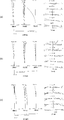
- FIG. 2 is a diagram illustrating various aberrations (spherical aberration diagram, astigmatism diagram, distortion diagram, coma diagram, and chromatic aberration diagram of magnification) at the time of focusing on infinity in the zoom lens ZL1 according to the first example. ) Shows the wide-angle end state, (b) shows the intermediate focal length state, and (c) shows the telephoto end state.
- FNO is an F number
- Y is an image height
- A is a half field angle (unit: °) with respect to each image height.
- d indicates the d-line
- g indicates the aberration at the g-line.
- Those not described indicate aberrations at the d-line.
- the solid line indicates the sagittal image plane and the broken line indicates the meridional image plane.
- the solid line indicates meridional coma aberration
- the dotted line indicates sagittal coma aberration
- the dotted line on the right side from the origin indicates the sagittal coma aberration generated in the meridional direction with respect to the d line
- the dotted line on the left side from the origin indicates the d line.
- the sagittal coma aberration generated in the sagittal direction is shown respectively.
- the zoom lens ZL (ZL2) according to the second example includes a first lens group G1 having negative refractive power arranged in order from the object side along the optical axis, and a positive refractive power.
- the distance between the first lens group G1 and the second lens group G2 decreases, and the distance between the second lens group G2 and the third lens group G3 increases.
- the first lens group G1 and the second lens group G2 move.
- the third lens group G3 is fixed and does not move during zooming.
- the first lens group G1 is composed of a negative lens L11 and a positive lens L12 arranged in order from the object side along the optical axis.
- the object-side and image-side lens surfaces of the negative lens L11 and the image-side lens surface of the positive lens L12 are both aspherical surfaces.
- the second lens group G2 is composed of a positive lens L21 and a cemented lens of a positive lens L22 and a negative lens L23 arranged in order from the object side along the optical axis. Both the object-side and image-side lens surfaces of the positive lens L21 are aspherical surfaces.
- the third lens group G3 is composed of only one positive lens L31.
- the lens surface on the image side of the positive lens L31 is an aspherical surface.
- a diaphragm S for determining an F-number is disposed between the first lens group G1 and the second lens group G2, and has the same trajectory as the second lens group G2 upon zooming from the wide-angle end state to the telephoto end state. Move with.
- the filter group FL is composed of a low-pass filter, an infrared cut filter, and the like for cutting a spatial frequency higher than the limit resolution of a solid-state imaging device (for example, CCD or CMOS) disposed on the image plane I. .
- a solid-state imaging device for example, CCD or CMOS
- Table 2 below shows the values of each item in the second example.
- Surface numbers 1 to 14 in Table 2 correspond to the respective optical surfaces having the curvature radii R1 to R14 shown in FIG.
- the first surface, the second surface, the fourth surface, the sixth surface, the seventh surface, and the twelfth surface are aspherical surfaces.
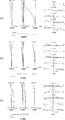
- FIG. 4 is a diagram showing various aberrations (spherical aberration diagram, astigmatism diagram, distortion diagram, coma diagram, and lateral chromatic aberration diagram) at the time of focusing on infinity in the zoom lens ZL2 according to Example 2. ) Shows the wide-angle end state, (b) shows the intermediate focal length state, and (c) shows the telephoto end state.
- the zoom lens ZL (ZL3) according to the third example includes a first lens group G1 having negative refractive power arranged in order from the object side along the optical axis, and positive refractive power.
- the distance between the first lens group G1 and the second lens group G2 decreases, and the distance between the second lens group G2 and the third lens group G3 increases.
- the first lens group G1 and the second lens group G2 move.
- the third lens group G3 is fixed and does not move during zooming.
- the first lens group G1 is composed of a negative lens L11 and a positive lens L12 arranged in order from the object side along the optical axis.
- the object side and image side lens surfaces of the negative lens L11 and the object side and image side lens surfaces of the positive lens L12 are both aspherical surfaces.
- the second lens group G2 is composed of a positive lens L21 and a cemented lens of a positive lens L22 and a negative lens L23 arranged in order from the object side along the optical axis. Both the object-side and image-side lens surfaces of the positive lens L21 are aspherical surfaces.
- the third lens group G3 is composed of only one positive lens L31.
- the lens surface on the image side of the positive lens L31 is an aspherical surface.
- a diaphragm S for determining an F-number is disposed between the first lens group G1 and the second lens group G2, and has the same trajectory as the second lens group G2 upon zooming from the wide-angle end state to the telephoto end state. Move with.
- the filter group FL is composed of a low-pass filter, an infrared cut filter, and the like for cutting a spatial frequency higher than the limit resolution of a solid-state imaging device (for example, CCD or CMOS) disposed on the image plane I. .
- a solid-state imaging device for example, CCD or CMOS
- Table 3 below shows the values of each item in the third example.
- Surface numbers 1 to 14 in Table 3 correspond to the respective optical surfaces having the curvature radii R1 to R14 shown in FIG.
- the first surface, the second surface, the third surface, the fourth surface, the sixth surface, the seventh surface, and the twelfth surface are aspherical surfaces.
- FIG. 6 is a diagram of various aberrations (spherical aberration diagram, astigmatism diagram, distortion diagram, coma diagram, and chromatic aberration diagram of magnification) at the time of focusing on infinity in the zoom lens ZL3 according to Example 3, (a ) Shows the wide-angle end state, (b) shows the intermediate focal length state, and (c) shows the telephoto end state.
- the zoom lens ZL (ZL4) according to the fourth example includes a first lens group G1 having negative refractive power arranged in order from the object side along the optical axis, and a positive refractive power.
- the distance between the first lens group G1 and the second lens group G2 decreases, and the distance between the second lens group G2 and the third lens group G3 increases.
- the first lens group G1, the second lens group G2, and the third lens group G3 move so that the distance between the third lens group G3 and the fourth lens group G4 decreases.
- the fourth lens group G4 is fixed and does not move during zooming.
- the first lens group G1 is composed of a negative lens L11 and a positive lens L12 arranged in order from the object side along the optical axis.
- the object-side and image-side lens surfaces of the negative lens L11 and the image-side lens surface of the positive lens L12 are both aspherical surfaces.
- the second lens group G2 is composed of a positive lens L21 and a cemented lens of a positive lens L22 and a negative lens L23 arranged in order from the object side along the optical axis. Both the object-side and image-side lens surfaces of the positive lens L21 are aspherical surfaces.
- the third lens group G3 is composed of only one positive lens L31.
- the lens surface on the image side of the positive lens L31 is an aspherical surface.
- the fourth lens group G4 is composed of only one negative lens L41.
- a diaphragm S for determining an F-number is disposed between the first lens group G1 and the second lens group G2, and has the same trajectory as the second lens group G2 upon zooming from the wide-angle end state to the telephoto end state. Move with.
- the filter group FL is composed of a low-pass filter, an infrared cut filter, and the like for cutting a spatial frequency higher than the limit resolution of a solid-state imaging device (for example, CCD or CMOS) disposed on the image plane I. .
- a solid-state imaging device for example, CCD or CMOS
- Table 4 below shows the values of each item in the fourth example.
- Surface numbers 1 to 16 in Table 4 correspond to the optical surfaces having the curvature radii R1 to R16 shown in FIG.
- the first surface, the second surface, the fourth surface, the sixth surface, the seventh surface, and the twelfth surface are aspherical surfaces.
- FIG. 8 is a diagram of various aberrations (spherical aberration diagram, astigmatism diagram, distortion diagram, coma diagram, and chromatic aberration diagram of magnification) at the time of focusing on infinity in the zoom lens ZL4 according to Example 4, and (a ) Shows the wide-angle end state, (b) shows the intermediate focal length state, and (c) shows the telephoto end state.
- various aberrations spherical aberration diagram, astigmatism diagram, distortion diagram, coma diagram, and chromatic aberration diagram of magnification
- the angle of view in the wide-angle end state is as wide as about 80 degrees while being small, and has a high zoom ratio of about 3 to 4 times.
- a zoom lens can be realized.
Landscapes
- Physics & Mathematics (AREA)
- General Physics & Mathematics (AREA)
- Optics & Photonics (AREA)
- Nonlinear Science (AREA)
- Lenses (AREA)
Abstract
光軸に沿って物体側から順に並んだ、負の屈折力を有する第1レンズ群(G1)と、正の屈折力を有する第2レンズ群(G2)と、第3レンズ群(G3)とを有し、広角端状態から望遠端状態への変倍に際し、第1レンズ群(G1)と第2レンズ群(G2)との間隔が減少し、第2レンズ群(G2)と第3レンズ群(G3)との間隔が増加するように、少なくとも第1レンズ群(G1)と第2レンズ群(G2)とが移動し、次の条件式を満足する。 0.80<(-f1)/(fw×ft)1/2<1.20 0.90<f2/fw<1.50 但し、f1:第1レンズ群(G1)の焦点距離、fw:ズームレンズ(ZL)の広角端状態における焦点距離、ft:ズームレンズ(ZL)の望遠端状態における焦点距離、f2:第2レンズ群(G2)の焦点距離。
Description
本発明は、スチルカメラ、デジタルカメラ等に好適なズームレンズ、光学機器及びズームレンズの変倍方法に関する。
近年、固体撮像素子を用いたデジタルスチルカメラや、デジタルビデオカメラ等の撮像装置(カメラ)が一般に広く普及している。これらの撮影装置では、撮像用レンズとしてズームレンズが用いられることが一般的である。撮影者に快適な撮影を提供するために、広角端状態において十分な画角を有し、望遠端状態に至るまでの変倍比が大きく、かつコンパクトなズームレンズが求められている。ズームレンズの小型化を実現した例として、特許文献1に記載の実施例2がある。
従来のズームレンズでは、極めて小型のズームレンズを実現しているが、広角端状態における画角がやや狭く、また変倍比も小さい。
本発明は、このような問題に鑑みてなされたものであり、小型でありながら、広角端状態における画角をより広く確保し、かつ高い変倍比を有するズームレンズ、光学機器及びズームレンズの変倍方法を提供することを目的とする。
このような目的を達成するため、本発明に係るズームレンズは、光軸に沿って物体側から順に並んだ、負の屈折力を有する第1レンズ群と、正の屈折力を有する第2レンズ群と、第3レンズ群とを有し、広角端状態から望遠端状態への変倍に際し、前記第1レンズ群と前記第2レンズ群との間隔が減少し、前記第2レンズ群と前記第3レンズ群との間隔が増加するように、少なくとも前記第1レンズ群と前記第2レンズ群とが移動し、次の条件式を満足する。
0.80 < (-f1)/(fw×ft)1/2 < 1.20
0.90 < f2/fw < 1.50
但し、
f1:前記第1レンズ群の焦点距離、
fw:前記ズームレンズの広角端状態における焦点距離、
ft:前記ズームレンズの望遠端状態における焦点距離、
f2:前記第2レンズ群の焦点距離。
0.90 < f2/fw < 1.50
但し、
f1:前記第1レンズ群の焦点距離、
fw:前記ズームレンズの広角端状態における焦点距離、
ft:前記ズームレンズの望遠端状態における焦点距離、
f2:前記第2レンズ群の焦点距離。
本発明に係るズームレンズは、次の条件式を満足することが好ましい。
0.20 < f2/f3 < 0.40
但し、
f3:第3レンズ群の焦点距離。
但し、
f3:第3レンズ群の焦点距離。
本発明に係るズームレンズは、次の条件式を満足することが好ましい。
0.45 < fw/(-f1) < 0.75
本発明に係るズームレンズは、次の条件式を満足することが好ましい。
1.50 < ft/(-f1) < 1.95
本発明に係るズームレンズは、次の条件式を満足することが好ましい。
1.75 < N
但し、
N:前記第1レンズ群と前記第2レンズ群とに含まれる、全てのレンズの光学部材のd線に対する屈折率の平均値。
但し、
N:前記第1レンズ群と前記第2レンズ群とに含まれる、全てのレンズの光学部材のd線に対する屈折率の平均値。
本発明に係るズームレンズにおいて、前記第1レンズ群は、光軸に沿って物体側から順に並んだ、1枚の負レンズと、1枚の正レンズとからなることが好ましい。
本発明に係るズームレンズにおいて、前記第2レンズ群は、光軸に沿って物体側から順に並んだ、2枚の正レンズと、1枚の負レンズとからなることが好ましい。
本発明に係る光学機器は、上述のズームレンズのいずれかを搭載する。
本発明に係るズームレンズの変倍方法は、光軸に沿って物体側から順に並んだ、負の屈折力を有する第1レンズ群と、正の屈折力を有する第2レンズ群と、第3レンズ群とを有し、以下の条件式を満足するズームレンズの変倍方法であって、広角端状態から望遠端状態への変倍に際し、前記第1レンズ群と前記第2レンズ群との間隔が減少し、前記第2レンズ群と前記第3レンズ群との間隔が増加するように、少なくとも前記第1レンズ群と前記第2レンズ群とが移動する。
0.80 < (-f1)/(fw×ft)1/2 < 1.20
0.90 < f2/fw < 1.50
但し、
f1:前記第1レンズ群の焦点距離、
fw:前記ズームレンズの広角端状態における焦点距離、
ft:前記ズームレンズの望遠端状態における焦点距離、
f2:前記第2レンズ群の焦点距離。
0.90 < f2/fw < 1.50
但し、
f1:前記第1レンズ群の焦点距離、
fw:前記ズームレンズの広角端状態における焦点距離、
ft:前記ズームレンズの望遠端状態における焦点距離、
f2:前記第2レンズ群の焦点距離。
本発明によれば、小型でありながら、広角端状態における画角をより広く確保し、かつ高い変倍比を有するズームレンズ、光学機器及びズームレンズの変倍方法を提供することができる。
以下、実施形態について、図面を参照しながら説明する。
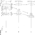
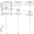
本実施形態に係るズームレンズZLは、図1に示すように、光軸に沿って物体側から順に並んだ、負の屈折力を有する第1レンズ群G1と、正の屈折力を有する第2レンズ群G2と、第3レンズ群G3とを有し、広角端状態から望遠端状態への変倍に際し、第1レンズ群G1と第2レンズ群G2との間隔が減少し、第2レンズ群G2と第3レンズ群G3との間隔が増加するように、少なくとも第1レンズ群G1と第2レンズ群G2とが移動するように構成される。
ズームレンズZLは、上記のように、物体側から順に並んだ、負、正、正の3つのレンズ群を有する、負先行型のズームレンズである。第2レンズ群G2は、変倍部かつマスターレンズ群である。第1レンズ群G1は、コンペンセータ群である。第3レンズ群G3は、ズームレンズ全系の射出瞳位置を撮像素子に対して最適化すると共に、第1レンズ群G1および第2レンズ群G2で補正しきれずに残った収差の補正を行う。
このような単純な構造のズームレンズZLを広角化し、十分な変倍比を確保し、かつコンパクトにするためには、各レンズ群のパワー配置、各レンズの光学材料の屈折率、レンズ構成等を適切に設定する必要がある。
本実施形態に係るズームレンズZLでは、広角化しつつ小型化するために、次の条件式(1)を満足することが好ましい。
0.80 < (-f1)/(fw×ft)1/2 < 1.20 …(1)
但し、
f1:第1レンズ群G1の焦点距離、
fw:ズームレンズZLの広角端状態における焦点距離、
ft:ズームレンズZLの望遠端状態における焦点距離。
但し、
f1:第1レンズ群G1の焦点距離、
fw:ズームレンズZLの広角端状態における焦点距離、
ft:ズームレンズZLの望遠端状態における焦点距離。
ズームレンズZLの変倍は、第1レンズ群G1が結像した像を、後続のレンズ群で拡大、縮小することにより行われる。ズームレンズZL全系の焦点距離、変倍比等の仕様が定まっている場合、第1レンズ群G1の焦点距離に応じて、後続のレンズ群の倍率が決まる。したがって、第1レンズ群G1の焦点距離は、ズームレンズZL全体の特性を決定する上で、極めて重要なパラメータである。条件式(1)は、この第1レンズ群G1の焦点距離の適切な範囲を規定するものである。
条件式(1)の下限値を下回ると、後続のレンズ群の倍率が高くなりすぎるために、望遠端状態においてズームレンズZLの全長が長くなりすぎる。また、望遠端状態における球面収差が補正困難となるため、好ましくない。条件式(1)の上限値を上回ると、後続のレンズ群の倍率が低くなりすぎるため、広角端状態においてズームレンズZLの全長が長くなりすぎ、前玉径も大きくなる。また、中間焦点距離状態から望遠端状態において、上コマ収差の補正が困難となるため、好ましくない。
本実施形態の効果を確実なものとするために、条件式(1)の下限値を0.85とすることが好ましい。本実施形態の効果を最大限に発揮するために、条件式(1)の下限値を0.90とすることが好ましい。
本実施形態の効果を確実なものとするために、条件式(1)の上限値を1.15とすることが好ましい。本実施形態の効果を最大限に発揮するために、条件式(1)の上限値を1.10とすることが好ましい。
上記のように構成されたズームレンズZLにおいて、次の条件式(2)を満足することが好ましい。
0.90 < f2/fw < 1.50 …(2)
但し、
f2:第2レンズ群G2の焦点距離。
但し、
f2:第2レンズ群G2の焦点距離。
条件式(2)は、第2レンズ群G2の焦点距離の適切な範囲を規定するものである。条件式(2)の下限値を下回ると、第2レンズ群G2の屈折力が強くなりすぎ、第2レンズ群G2で発生する球面収差の補正が困難となるため、好ましくない。また、ペッツバール和が著しく大きくなり、中間焦点距離状態から望遠端状態において像面湾曲と非点隔差を同時に補正することができなくなる。条件式(2)の上限値を上回ると、ペッツバール和が著しく小さくなり、中間焦点距離状態から望遠端状態において像面湾曲と非点隔差を同時に補正することができなくなるため、好ましくない。
本実施形態の効果を確実なものとするために、条件式(2)の下限値を0.95とすることが好ましい。本実施形態の効果を最大限に発揮するために、条件式(2)の下限値を1.00とすることが好ましい。
本実施形態の効果を確実なものとするために、条件式(2)の上限値を1.45とすることが好ましい。本実施形態の効果を最大限に発揮するために、条件式(2)の上限値を1.40とすることが好ましい。
上記のように構成されたズームレンズZLにおいて、次の条件式(3)を満足することが好ましい。
0.20 < f2/f3 < 0.40 …(3)
但し、
f3:第3レンズ群G3の焦点距離。
但し、
f3:第3レンズ群G3の焦点距離。
条件式(3)は、第2レンズ群G2と第3レンズ群G3の焦点距離の比率について、適切な範囲を規定するものである。条件式(3)の下限値を下回ると、ズームレンズZL全系の射出瞳位置が撮像面に接近しすぎるため、好ましくない。また、広角端状態における像面湾曲の補正が困難となる。条件式(3)の上限値を上回ると、ペッツバール和が著しく大きくなるため、中間焦点距離状態から望遠端状態において像面湾曲と非点隔差の補正が困難となるため、好ましくない。
本実施形態の効果を確実なものとするために、条件式(3)の下限値を0.24とすることが好ましい。本実施形態の効果を最大限に発揮するために、条件式(3)の下限値を0.27とすることが好ましい。
本実施形態の効果を確実なものとするために、条件式(3)の上限値を0.39とすることが好ましい。本実施形態の効果を最大限に発揮するために、条件式(3)の上限値を0.37とすることが好ましい。
上記のように構成されたズームレンズZLにおいて、次の条件式(4)を満足することが好ましい。
0.45 < fw/(-f1) < 0.75 …(4)
条件式(4)は、広角端状態におけるズームレンズZL全系の焦点距離と第1レンズ群G1の焦点距離の比率について、適切な範囲を規定するものである。条件式(4)の下限値を下回ると、広角端状態におけるコマ収差、像面湾曲の補正が困難となるため、好ましくない。条件式(4)の上限値を上回ると、広角端状態から望遠端状態への変倍による球面収差の変動が非常に大きくなり、広角端状態と望遠端状態の両方で球面収差を補正することが困難になるため、好ましくない。
本実施形態の効果を確実なものとするために、条件式(4)の下限値を0.46とすることが好ましい。本実施形態の効果を最大限に発揮するために、条件式(4)の下限値を0.47とすることが好ましい。
本実施形態の効果を確実なものとするために、条件式(4)の上限値を0.70とすることが好ましい。本実施形態の効果を最大限に発揮するために、条件式(4)の上限値を0.65とすることが好ましい。
上記のように構成されたズームレンズZLにおいて、次の条件式(5)を満足することが好ましい。
1.50 < ft/(-f1) < 1.95 …(5)
条件式(5)は、望遠端状態におけるズームレンズZLの全系の焦点距離と第1レンズ群G1の焦点距離の比率について、適切な範囲を規定するものである。条件式(5)の下限を下回ると、広角端状態におけるコマ収差、像面湾曲の補正が困難となるため、好ましくない。条件式(5)の上限値を上回ると、望遠端状態における球面収差の補正が困難となるため、好ましくない。
本実施形態の効果を確実なものとするために、条件式(5)の下限値を1.54とすることが好ましい。本実施形態の効果を最大限に発揮するために、条件式(5)の下限値を1.58とすることが好ましい。
本実施形態の効果を確実なものとするために、条件式(5)の上限値を1.90とすることが好ましい。本実施形態の効果を最大限に発揮するために、条件式(5)の上限値を1.85とすることが好ましい。
上記のように構成されたズームレンズZLにおいて、次の条件式(6)を満足することが好ましい。
1.75 < N …(6)
但し、
N:第1レンズ群G1と第2レンズ群G2とに含まれる、全てのレンズの光学部材のd線に対する屈折率の平均値。
但し、
N:第1レンズ群G1と第2レンズ群G2とに含まれる、全てのレンズの光学部材のd線に対する屈折率の平均値。
条件式(6)は、第1レンズ群G1と第2レンズ群G2に含まれる全てのレンズの光学部材の屈折率について、適切な範囲を規定するものである。条件式(6)の下限値を下回ると、第1レンズ群G1および第2レンズ群G2に含まれる各レンズの曲率半径が小さくなりすぎるために、ズーム全域において球面収差、コマ収差の補正が困難となるため、好ましくない。
本実施形態の効果を確実なものとするために、条件式(6)の上限値を1.78とすることが好ましい。本実施形態の効果を最大限に発揮するために、条件式(6)の上限値を1.80とすることが好ましい。
上記のように構成されたズームレンズZLにおいて、第1レンズ群G1は、光軸に沿って物体側から順に並んだ、1枚の負レンズと、1枚の正レンズとから構成されることが好ましい。この構成は、第1レンズ群G1の色収差、球面収差、コマ収差、非点格差を補正可能な最小枚数のレンズ構成であり、光学性能を低下させずに、ズームレンズZLを広角化、小型化するために必要な条件となっている。
上記のように構成されたズームレンズZLにおいて、第2レンズ群G2は、光軸に沿って物体側から順に並んだ、2枚の正レンズと、1枚の負レンズとから構成されることが好ましい。この構成により、第1レンズ群G1で発散された光束に対して、第2レンズ群G2で球面収差を過剰に発生させることなく、収斂作用を発揮することができる。また、第2レンズ群G2の後側主点を物体側に移動させることが可能となり、望遠端状態において第1レンズ群G1と第2レンズ群G2との間隔確保が容易になる。
本実施形態に係るズームレンズZLにおいて、無限遠物体から至近距離物体へのフォーカシングは、第1レンズ群G1あるいは第3レンズ群G3を物体側に繰り出すことによって行うことが可能である。しかしながら、第1レンズ群G1を繰り出す方法では、至近撮影時に画面周辺部の光量低下を招きやすいため、第3レンズ群G3を物体側に繰り出すことによって行うことがより望ましい。
本実施形態に係るズームレンズZLにおいて、各レンズ面のうち任意の面を、回折面としてもよい。また、任意のレンズを、屈折率分布型レンズ(GRINレンズ)あるいはプラスチックレンズとしてもよい。また、第3レンズ群G3の像側に、屈折力が小さなレンズ群を付加してもよい。
本実施形態に係るズームレンズZLにおいて、各レンズ群のうち、1つのレンズ群全体又はその一部のレンズを光軸と略垂直な方向に移動させる構成とすることもできる。この構成により、像面上の像を移動させることが可能となり、いわゆる防振レンズを実現することができる。
以上のような構成を有する本実施形態によれば、極めて小型でありながら、広角端状態における画角をより広く確保し(80度程度)、かつ高い変倍比を有する(3~4倍程度)、ズームレンズZLを実現することができる。
図9及び図10に、撮影レンズとして上述のズームレンズZLを備える、デジタルスチルカメラCAM(光学機器)の構成を示す。このデジタルスチルカメラCAMは、不図示の電源釦を押すと、撮影レンズ(ズームレンズZL)の不図示のシャッタが開放されて、ズームレンズZLで被写体(物体)からの光が集光され、像面I(図1参照)に配置された撮像素子C(例えば、CCDやCMOS等)に結像される。撮像素子Cに結像された被写体像は、デジタルスチルカメラCAMの背後に配置された液晶モニターMに表示される。撮影者は、液晶モニターMを見ながら被写体像の構図を決めた後、レリーズ釦B1を押し下げて被写体像を撮像素子Cで撮影し、不図示のメモリーに記録保存する。
カメラCAMには、被写体が暗い場合に補助光を発光する補助光発光部EF、デジタルスチルカメラCAMの種々の条件設定等に使用するファンクションボタンB2等が配置されている。ここでは、カメラCAMとズームレンズZLとが一体に成形されたコンパクトタイプのカメラを例示したが、光学機器としては、ズームレンズZLを有するレンズ鏡筒とカメラボディ本体とが着脱可能な一眼レフカメラでも良い。
上記構成のカメラCAMによれば、撮影レンズとして本実施形態に係るズームレンズZLを搭載することにより、小型でありながら、広角端状態における画角をより広く確保し、かつ高い変倍比を有するカメラを実現することができる。
本実施形態に係るズームレンズZLの変倍方法は、光軸に沿って物体側から順に並んだ、負の屈折力を有する第1レンズ群G1と、正の屈折力を有する第2レンズ群G2と、第3レンズ群G3とを有し、次の条件式(1),(2)を満足するズームレンズZLにおいて、図1に示すように、広角端状態(W)から中間焦点距離状態(M)を経て望遠端状態(T)への変倍に際し、第1レンズ群G1と第2レンズ群G2との間隔が減少し、第2レンズ群G2と第3レンズ群G3との間隔が増加するように、少なくとも第1レンズ群G1と第2レンズ群G2とを移動させる。
0.80 < (-f1)/(fw×ft)1/2 < 1.20 …(1)
0.90 < f2/fw < 1.50 …(2)
但し、
f1:第1レンズ群G1の焦点距離、
fw:ズームレンズZLの広角端状態における焦点距離、
ft:ズームレンズZLの望遠端状態における焦点距離、
f2:第2レンズ群G2の焦点距離。
0.90 < f2/fw < 1.50 …(2)
但し、
f1:第1レンズ群G1の焦点距離、
fw:ズームレンズZLの広角端状態における焦点距離、
ft:ズームレンズZLの望遠端状態における焦点距離、
f2:第2レンズ群G2の焦点距離。
上記の変倍方法によれば、ズームレンズZLにおいて、小型化を図りつつ、広角端状態における画角をより広く確保し(80度程度)、かつ高い変倍比を達成する(3~4倍程度)ことができる。
これより本実施形態に係る各実施例について、図面に基づいて説明する。以下に、表1~表4を示すが、これらは第1実施例~第4実施例における各諸元の表である。
第1実施例に係る図1に対する各参照符号は、参照符号の桁数の増大による説明の煩雑化を避けるため、実施例ごとに独立して用いている。ゆえに、他の実施例に係る図面と共通の参照符号を付していても、それらは他の実施例とは必ずしも共通の構成ではない。
各実施例では収差特性の算出対象として、d線(波長587.5620nm)、g線(波長435.8350nm)を選んでいる。
表中の[全体諸元]において、fは各状態におけるズームレンズZL全系の焦点距離、FnoはFナンバー、2ωは画角(単位:°)、Ymaxは最大像高をそれぞれ示す。
表中の[レンズ諸元]において、面番号は光線の進行する方向に沿った物体側からの光学面の順序、Rは各光学面の曲率半径、Dは各光学面から次の光学面(又は像面)までの光軸上の距離である面間隔、ndは光学部材の材質のd線に対する屈折率、νdは光学部材の材質のd線を基準とするアッベ数をそれぞれ示す。物面は物体面、(可変)は可変の面間隔、曲率半径の「∞」は平面又は開口、(絞りS)は開口絞りS、像面は像面Iをそれぞれ示す。空気の屈折率「1.00000」は省略する。光学面が非球面である場合には、面番号に*印を付し、曲率半径Rの欄には近軸曲率半径を示す。
表中の[非球面データ]には、[レンズ諸元]に示した非球面について、その形状を次式(a)で示す。X(y)は非球面の頂点における接平面から高さyにおける非球面上の位置までの光軸方向に沿った距離を、rは基準球面の曲率半径(近軸曲率半径)を、κは円錐定数を、Aiは第i次の非球面係数を示す。「E-n」は、「×10-n」を示す。例えば、1.234E-05=1.234×10⁻⁵である。
X(y)=(y2/r)/{1+(1-κ×y2/r2)1/2}
+A4×y4+A6×y6+A8×y8+A10×y10 …(a)
+A4×y4+A6×y6+A8×y8+A10×y10 …(a)
表中の[可変間隔データ]において、広角端状態、中間焦点距離状態、望遠端状態のそれぞれにおける各可変間隔Di(第i面と第(i+1)面との可変間隔)、TLはズームレンズZL全長、BFはバックフォーカス(最も像側に配置されている光学部材の像側の面から近軸像面までの距離)を示す。
表中の[レンズ群データ]において、Gは群番号、群初面は各群の最も物体側の面番号を、群焦点距離は各群の焦点距離を示す。
表中の[条件式]において、上記の条件式(1)~(6)に対応する値を示す。
以下、全ての諸元値において、掲載されている焦点距離f、曲率半径R、面間隔D、その他の長さ等は、特記のない場合一般に「mm」が使われるが、光学系は比例拡大又は比例縮小しても同等の光学性能が得られるので、これに限られるものではない。また、単位は「mm」に限定されることなく、他の適当な単位を用いることが可能である。
ここまでの表の説明は全ての実施例において共通であり、以下での説明を省略する。
(第1実施例)
第1実施例について、図1,図2及び表1を用いて説明する。第1実施例に係るズームレンズZL(ZL1)は、図1に示すように、光軸に沿って物体側から順に並んだ、負の屈折力を持つ第1レンズ群G1と、正の屈折力を持つ第2レンズ群G2と、正の屈折力を持つ第3レンズ群G3と、フィルタ群FLとから構成されている。
第1実施例について、図1,図2及び表1を用いて説明する。第1実施例に係るズームレンズZL(ZL1)は、図1に示すように、光軸に沿って物体側から順に並んだ、負の屈折力を持つ第1レンズ群G1と、正の屈折力を持つ第2レンズ群G2と、正の屈折力を持つ第3レンズ群G3と、フィルタ群FLとから構成されている。
そして、広角端状態から望遠端状態への変倍に際し、第1レンズ群G1と第2レンズ群G2との間隔が減少し、第2レンズ群G2と第3レンズ群G3との間隔が増加するように、第1レンズ群G1と第2レンズ群G2とが移動する。第3レンズ群G3は、固定されており、ズーミングに際しても移動しない。
第1レンズ群G1は、光軸に沿って物体側から順に並んだ、負レンズL11と、正レンズL12とから構成されている。負レンズL11の物体側および像側のレンズ面、正レンズL12の像側のレンズ面は、いずれも非球面である。
第2レンズ群G2は、光軸に沿って物体側から順に並んだ、正レンズL21と、正レンズL22と負レンズL23との接合レンズとから構成されている。正レンズL21の物体側および像側のレンズ面は、いずれも非球面である。
第3レンズ群G3は、1枚の正レンズL31のみで構成されている。正レンズL31の像側のレンズ面は、非球面である。
Fナンバーを決定する絞りSは、第1レンズ群G1と第2レンズ群G2との間に配置されており、広角端状態から望遠端状態への変倍に際し、第2レンズ群G2と同一軌道で移動する。
フィルタ群FLは、像面Iに配設される固体撮像素子(例えば、CCDやCMOS)の限界解像以上の空間周波数をカットするためのローパスフィルタや赤外カットフィルタ等で構成されている。
下記の表1に、第1実施例における各諸元の値を示す。表1における面番号1~14が、図1に示す曲率半径R1~R14の各光学面に対応している。第1実施例では、第1面、第2面,第4面,第6面,第7面,第12面が非球面である。
(表1)
[全体諸元]
広角端状態 中間焦点距離状態 望遠端状態
f 5.15 8.70 14.70
Fno 3.34 4.49 6.44
2ω 80.45 51.65 31.39
Ymax 3.50 3.90 3.90
[レンズ諸元]
面番号 R D nd νd
物面 ∞
*1 -19.1765 0.4500 1.88202 37.23
*2 5.7448 0.5200
3 6.0802 1.2500 1.92286 20.88
*4 11.5477 D4(可変)
5 ∞ -0.0500(Fno決定面)
*6 5.8378 1.1500 1.59201 67.05
*7 -6.9426 0.1500
8 3.4770 1.1000 1.88300 40.66
9 391.4576 0.4000 1.95000 29.37
10 2.4300 D10(可変)
11 -1000.0000 1.8000 1.53153 55.95
*12 -9.5350 D12(可変)
13 ∞ 0.5000 1.51680 63.88
14 ∞ BF
像面 ∞
[非球面データ]
(第1面)
κ=1.0000,A4=2.74116E-03,A6=-1.23404E-04,A8=0.00000E+00,A10=0.00000E+00
(第2面)
κ=-0.0890,A4=4.55493E-03,A6=3.18602E-04,A8=-1.25219E-06,A10=-3.04823E-06
(第4面)
κ=1.0000,A4=-5.46977E-04,A6=-3.42618E-04,A8=4.40386E-05,A10=-1.48556E-06
(第6面)
κ=1.0000,A4=-1.73166E-03,A6=0.00000E+00,A8=0.00000E+00,A10=0.00000E+00
(第7面)
κ=0.0281,A4=-1.28778E-04,A6=0.00000E+00,A8=0.00000E+00,A10=0.00000E+00
(第12面)
κ=-8.8758,A4=-1.11069E-03,A6=1.29644E-05,A8=-1.71727E-07,A10=0.00000E+00
[可変間隔データ]
広角端状態 中間焦点距離状態 望遠端状態
無限遠 無限遠 無限遠
f 5.15 8.70 14.70
D4 4.9573 2.0187 0.2787
D10 2.5060 5.3490 10.1541
D12 2.0682 2.0682 2.0682
BF 0.6000 0.6000 0.6000
TL 17.4015 17.3059 20.3710
[レンズ群データ]
群番号 群初面 群焦点距離
G1 1 -8.15
G2 6 5.45
G3 11 18.10
[条件式]
条件式(1) (-f1)/(fw×ft)1/2 = 0.9367
条件式(2) f2/fw = 1.0583
条件式(3) f2/f3 = 0.2962
条件式(4) fw/(-f1) = 0.6319
条件式(5) ft/(-f1) = 1.8037
条件式(6) N = 1.8460
表1から、本実施例に係るズームレンズZL1は、条件式(1)~(6)を満たすことが分かる。
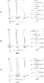
図2は、第1実施例に係るズームレンズZL1における無限遠合焦時の諸収差図(球面収差図,非点収差図,歪曲収差図,コマ収差図及び倍率色収差図)であり、(a)は広角端状態、(b)は中間焦点距離状態、(c)は望遠端状態をそれぞれ示す。
各収差図において、FNOはFナンバー、Yは像高、Aは各像高に対する半画角(単位:°)をそれぞれ示す。dはd線、gはg線における収差をそれぞれ示す。記載のないものは、d線における収差を示す。非点収差図において、実線はサジタル像面、破線はメリディオナル像面を示す。コマ収差図において、実線はメリディオナルコマ収差、点線はサジタルコマ収差を示し、原点より右側の点線はd線に対してメリディオナル方向に発生するサジタルコマ収差、原点より左側の点線はd線に対してサジタル方向に発生するサジタルコマ収差をそれぞれ示す。
これら収差図に関する説明は、他の実施例においても同様とし、その説明を省略する。
各収差図から明らかなように、第1実施例では、広角端状態から望遠端状態までの各焦点距離状態において諸収差が良好に補正され、優れた光学性能を有することが分かる。
(第2実施例)
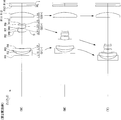
第2実施例について、図3,図4及び表2を用いて説明する。第2実施例に係るズームレンズZL(ZL2)は、図3に示すように、光軸に沿って物体側から順に並んだ、負の屈折力を持つ第1レンズ群G1と、正の屈折力を持つ第2レンズ群G2と、正の屈折力を持つ第3レンズ群G3と、フィルタ群FLとから構成されている。
第2実施例について、図3,図4及び表2を用いて説明する。第2実施例に係るズームレンズZL(ZL2)は、図3に示すように、光軸に沿って物体側から順に並んだ、負の屈折力を持つ第1レンズ群G1と、正の屈折力を持つ第2レンズ群G2と、正の屈折力を持つ第3レンズ群G3と、フィルタ群FLとから構成されている。
そして、広角端状態から望遠端状態への変倍に際し、第1レンズ群G1と第2レンズ群G2との間隔が減少し、第2レンズ群G2と第3レンズ群G3との間隔が増加するように、第1レンズ群G1と第2レンズ群G2とが移動する。第3レンズ群G3は、固定されており、ズーミングに際しても移動しない。
第1レンズ群G1は、光軸に沿って物体側から順に並んだ、負レンズL11、正レンズL12とから構成されている。負レンズL11の物体側および像側のレンズ面、正レンズL12の像側のレンズ面は、いずれも非球面である。
第2レンズ群G2は、光軸に沿って物体側から順に並んだ、正レンズL21と、正レンズL22と負レンズL23との接合レンズとから構成されている。正レンズL21の物体側および像側のレンズ面は、いずれも非球面である。
第3レンズ群G3は、1枚の正レンズL31のみで構成されている。正レンズL31の像側のレンズ面は、非球面である。
Fナンバーを決定する絞りSは、第1レンズ群G1と第2レンズ群G2との間に配置されており、広角端状態から望遠端状態への変倍に際し、第2レンズ群G2と同一軌道で移動する。
フィルタ群FLは、像面Iに配設される固体撮像素子(例えば、CCDやCMOS)の限界解像以上の空間周波数をカットするための、ローパスフィルタや赤外カットフィルタ等で構成されている。
下記の表2に、第2実施例における各諸元の値を示す。表2における面番号1~14が、図3に示す曲率半径R1~R14の各光学面に対応している。第2実施例では、第1面,第2面,第4面,第6面,第7面,第12面が非球面である。
(表2)
[全体諸元]
広角端状態 中間焦点距離状態 望遠端状態
f 5.15 8.70 14.70
Fno 3.52 4.68 6.64
2ω 79.99 51.36 31.13
Ymax 3.50 3.90 3.90
[レンズ諸元]
面番号 R D nd νd
物面 ∞
*1 435.3026 0.4500 1.85135 40.10
*2 5.0647 0.8000
3 8.6549 1.2500 1.92286 20.88
*4 16.9171 D4(可変)
5 ∞ -0.2500(Fno決定面)
*6 4.6737 1.2500 1.61881 63.86
*7 -9.4864 0.1500
8 4.1171 1.1000 1.88300 40.66
9 105.3274 0.4000 1.95000 29.37
10 2.5875 D10(可変)
11 -1000.0000 1.7500 1.53153 55.95
*12 -10.0042 D12(可変)
13 ∞ 0.5000 1.51680 63.88
14 ∞ BF
像面 ∞
[非球面データ]
(第1面)
κ=1.0000,A4=-1.12000E-03,A6=6.71000E-05,A8=0.00000E+00,A10=0.00000E+00
(第2面)
κ=1.0000,A4=-6.94000E-05,A6=1.62000E-04,A8=-2.24000E-05,A10=2.82000E-06
(第4面)
κ=1.0000,A4=-1.34000E-03,A6=7.35000E-05,A8=-8.37000E-06,A10=-2.02000E-07
(第6面)
κ=1.2387,A4=-1.19000E-03,A6=0.00000E+00,A8=0.00000E+00,A10=0.00000E+00
(第7面)
κ=-11.3351,A4=0.00000E+00,A6=0.00000E+00,A8=0.00000E+00,A10=0.00000E+00
(第12面)
κ=0.0561,A4=-8.79000E-06,A6=-9.31000E-06,A8=7.10000E-06,A10=0.00000E+00
[可変間隔データ]
広角端状態 中間焦点距離状態 望遠端状態
無限遠 無限遠 無限遠
f 5.15 8.70 14.70
D4 6.2273 2.5993 0.4510
D10 2.5131 5.2577 9.8966
D12 2.1884 2.1884 2.1884
BF 0.6000 0.6000 0.6000
TL 18.9288 18.0454 20.5360
[レンズ群データ]
群番号 群初面 群焦点距離
G1 1 -9.20
G2 6 5.95
G3 11 19.00
[条件式]
条件式(1) (-f1)/(fw×ft)1/2 = 1.0763
条件式(2) f2/fw = 1.1972
条件式(3) f2/f3 = 0.3132
条件式(4) fw/(-f1) = 0.5402
条件式(5) ft/(-f1) = 1.5978
条件式(6) N = 1.8452
表2から、本実施例に係るズームレンズZL2は、条件式(1)~(6)を満たすことが分かる。
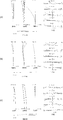
図4は、第2実施例に係るズームレンズZL2における無限遠合焦時の諸収差図(球面収差図,非点収差図,歪曲収差図,コマ収差図及び倍率色収差図)であり、(a)は広角端状態、(b)は中間焦点距離状態、(c)は望遠端状態をそれぞれ示す。
各収差図から明らかなように、第2実施例では、広角端状態から望遠端状態までの各焦点距離状態において諸収差が良好に補正され、優れた光学性能を有することが分かる。
(第3実施例)
第3実施例について、図5,図6及び表3を用いて説明する。第3実施例に係るズームレンズZL(ZL3)は、図5に示すように、光軸に沿って物体側から順に並んだ、負の屈折力を持つ第1レンズ群G1と、正の屈折力を持つ第2レンズ群G2と、正の屈折力を持つ第3レンズ群G3と、フィルタ群FLとから構成されている。
第3実施例について、図5,図6及び表3を用いて説明する。第3実施例に係るズームレンズZL(ZL3)は、図5に示すように、光軸に沿って物体側から順に並んだ、負の屈折力を持つ第1レンズ群G1と、正の屈折力を持つ第2レンズ群G2と、正の屈折力を持つ第3レンズ群G3と、フィルタ群FLとから構成されている。
そして、広角端状態から望遠端状態への変倍に際し、第1レンズ群G1と第2レンズ群G2との間隔が減少し、第2レンズ群G2と第3レンズ群G3との間隔が増加するように、第1レンズ群G1と第2レンズ群G2とが移動する。第3レンズ群G3は、固定されており、ズーミングに際しても移動しない。
第1レンズ群G1は、光軸に沿って物体側から順に並んだ、負レンズL11、正レンズL12とから構成されている。負レンズL11の物体側および像側のレンズ面、正レンズL12の物体側および像側のレンズ面は、いずれも非球面である。
第2レンズ群G2は、光軸に沿って物体側から順に並んだ、正レンズL21と、正レンズL22と負レンズL23との接合レンズとから構成されている。正レンズL21の物体側および像側のレンズ面は、いずれも非球面である。
第3レンズ群G3は、1枚の正レンズL31のみで構成されている。正レンズL31の像側のレンズ面は、非球面である。
Fナンバーを決定する絞りSは、第1レンズ群G1と第2レンズ群G2との間に配置されており、広角端状態から望遠端状態への変倍に際し、第2レンズ群G2と同一軌道で移動する。
フィルタ群FLは、像面Iに配設される固体撮像素子(例えば、CCDやCMOS)の限界解像以上の空間周波数をカットするための、ローパスフィルタや赤外カットフィルタ等で構成されている。
下記の表3に、第3実施例における各諸元の値を示す。表3における面番号1~14が、図5に示す曲率半径R1~R14の各光学面に対応している。第3実施例では、第1面,第2面,第3面,第4面,第6面,第7面,第12面が非球面である。
(表3)
[全体諸元]
広角端状態 中間焦点距離状態 望遠端状態
f 5.15 10.00 19.40
Fno 3.07 4.34 6.82
2ω 80.16 44.99 23.91
Ymax 3.50 3.90 3.90
[レンズ諸元]
面番号 R D nd νd
物面 ∞
*1 -33.34557 0.4500 1.88202 37.23
*2 6.20522 0.8300
*3 8.30745 1.3500 1.92286 20.88
*4 21.49237 D4(可変)
5 ∞ -0.2500(Fno決定面)
*6 4.84551 1.3500 1.61881 63.90
*7 -12.05761 0.1500
8 4.43946 1.2000 1.80400 46.60
9 -1000.00000 0.4000 1.90366 31.30
10 2.73022 D10(可変)
11 -1000.00000 1.6500 1.53153 55.95
*12 -10.78509 D12(可変)
13 ∞ 0.5000 1.51680 63.88
14 ∞ BF
像面 ∞
[非球面データ]
(第1面)
κ=1.0000,A4=5.48370E-04,A6=-9.24590E-06,A8=0.00000E+00,A10=0.00000E+00
(第2面)
κ=0.5186,A4=3.78770E-04,A6=1.00530E-04,A8=-4.44450E-06,A10=1.28750E-07
(第3面)
κ=-3.0000,A4=0.00000E+00,A6=0.00000E+00,A8=0.00000E+00,A10=0.00000E+00
(第4面)
κ=1.0000,A4=-7.52260E-04,A6=-4.18450E-05,A8=3.41160E-06,A10=-1.44570E-07
(第6面)
κ=-0.0004,A4=8.58050E-05,A6=0.00000E+00,A8=0.00000E+00,A10=0.00000E+00
(第7面)
κ=-9.6206,A4=0.00000E+00,A6=0.00000E+00,A8=0.00000E+00,A10=0.00000E+00
(第12面)
κ=-2.8761,A4=-1.81640E-04,A6=-1.27780E-05,A8=3.01010E-07,A10=0.00000E+00
[可変間隔データ]
広角端状態 中間焦点距離状態 望遠端状態
無限遠 無限遠 無限遠
f 5.15 10.00 19.40
D4 9.7400 3.6057 0.4496
D10 3.2331 7.0716 14.5112
D12 2.3621 2.3621 2.3621
BF 0.6000 0.6000 0.6000
TL 23.5652 21.2694 25.5529
[レンズ群データ]
群番号 群初面 群焦点距離
G1 1 -10.80
G2 6 7.18
G3 11 20.50
[条件式]
条件式(1) (-f1)/(fw×ft)1/2 = 1.0805
条件式(2) f2/fw = 1.3942
条件式(3) f2/f3 = 0.3132
条件式(4) fw/(-f1) = 0.4769
条件式(5) ft/(-f1) = 1.7963
条件式(6) N = 1.8263
表3から、本実施例に係るズームレンズZL3は、条件式(1)~(6)を満たすことが分かる。
図6は、第3実施例に係るズームレンズZL3における無限遠合焦時の諸収差図(球面収差図,非点収差図,歪曲収差図,コマ収差図及び倍率色収差図)であり、(a)は広角端状態、(b)は中間焦点距離状態、(c)は望遠端状態をそれぞれ示す。
各収差図から明らかなように、第3実施例では、広角端状態から望遠端状態までの各焦点距離状態において諸収差が良好に補正され、優れた光学性能を有することが分かる。
(第4実施例)
第4実施例について、図7,図8及び表4を用いて説明する。第4実施例に係るズームレンズZL(ZL4)は、図7に示すように、光軸に沿って物体側から順に並んだ、負の屈折力を持つ第1レンズ群G1と、正の屈折力を持つ第2レンズ群G2と、正の屈折力を持つ第3レンズ群G3と、負の屈折力を持つ第4レンズ群G4と、フィルタ群FLとから構成されている。
第4実施例について、図7,図8及び表4を用いて説明する。第4実施例に係るズームレンズZL(ZL4)は、図7に示すように、光軸に沿って物体側から順に並んだ、負の屈折力を持つ第1レンズ群G1と、正の屈折力を持つ第2レンズ群G2と、正の屈折力を持つ第3レンズ群G3と、負の屈折力を持つ第4レンズ群G4と、フィルタ群FLとから構成されている。
そして、広角端状態から望遠端状態への変倍に際し、第1レンズ群G1と第2レンズ群G2との間隔が減少し、第2レンズ群G2と第3レンズ群G3との間隔が増加し、第3レンズ群G3と第4レンズ群G4との間隔が減少するように、第1レンズ群G1と第2レンズ群G2と第3レンズ群G3とが移動する。第4レンズ群G4は固定されており、ズーミングに際しても移動しない。
第1レンズ群G1は、光軸に沿って物体側から順に並んだ、負レンズL11、正レンズL12とから構成されている。負レンズL11の物体側および像側のレンズ面、正レンズL12の像側のレンズ面は、いずれも非球面である。
第2レンズ群G2は、光軸に沿って物体側から順に並んだ、正レンズL21と、正レンズL22と負レンズL23との接合レンズとから構成されている。正レンズL21の物体側および像側のレンズ面は、いずれも非球面である。
第3レンズ群G3は、1枚の正レンズL31のみで構成されている。正レンズL31の像側のレンズ面は、非球面である。
第4レンズ群G4は、1枚の負レンズL41のみで構成されている。
Fナンバーを決定する絞りSは、第1レンズ群G1と第2レンズ群G2との間に配置されており、広角端状態から望遠端状態への変倍に際し、第2レンズ群G2と同一軌道で移動する。
フィルタ群FLは、像面Iに配設される固体撮像素子(例えば、CCDやCMOS)の限界解像以上の空間周波数をカットするための、ローパスフィルタや赤外カットフィルタ等で構成されている。
下記の表4に、第4実施例における各諸元の値を示す。表4における面番号1~16が、図7に示す曲率半径R1~R16の各光学面に対応している。第4実施例では、第1面,第2面,第4面,第6面,第7面,第12面が非球面である。
(表4)
[全体諸元]
広角端状態 中間焦点距離状態 望遠端状態
f 5.15 8.70 14.70
Fno 3.33 4.51 6.49
2ω 80.46 51.68 31.36
Ymax 3.50 3.90 3.90
[レンズ諸元]
面番号 R D nd νd
物面 ∞
*1 -19.17647 0.4500 1.88202 37.23
*2 5.74480 0.5200
3 6.65091 1.2500 1.92286 20.88
*4 13.86157 D4(可変)
5 ∞ -0.2500(Fno決定面)
*6 5.17925 1.1500 1.55332 71.67
*7 -6.68617 0.1500
8 3.57518 1.1000 1.88300 40.66
9 27.96776 0.4000 1.95000 29.37
10 2.46059 D10(可変)
11 205.97218 1.8000 1.53153 55.95
*12 -10.06147 D12(可変)
13 -25.00000 0.8000 1.53153 55.95
14 -47.72432 D14(可変)
15 ∞ 0.5000 1.51680 63.88
16 ∞ BF
像面 ∞
[非球面データ]
(第1面)
κ=1.0000,A4=2.77819-03,A6=-1.60764E-04,A8=0.00000E+00,A10=0.00000E+00
(第2面)
κ=-0.7697,A4=5.08507E-03,A6=2.61817E-04,A8=4.78303E-06,A10=-5.80289E-06
(第4面)
κ=1.0000,A4=-7.38048E-04,A6=-3.11158E-04,A8=2.78658E-05,A10=1.62279E-06
(第6面)
κ=1.0000,A4=-1.79129E-03,A6=0.00000E+00,A8=0.00000E+00,A10=0.00000E+00
(第7面)
κ=1.1658,A4=8.40262E-04,A6=0.00000E+00,A8=0.00000E+00,A10=0.00000E+00
(第12面)
κ=-9.0067,A4=-9.88220E-04,A6=5.46450E-06,A8=-2.29174E-08,A10=0.00000E+00
[可変間隔データ]
広角端状態 中間焦点距離状態 望遠端状態
無限遠 無限遠 無限遠
f 5.15 8.70 14.70
D4 4.8305 1.9880 0.2793
D10 1.9309 5.0665 10.0202
D12 1.6673 1.3998 1.0975
D14 0.4998 0.4998 0.4998
BF 0.4000 0.4000 0.4000
TL 17.3985 17.4240 20.3667
[レンズ群データ]
群番号 群初面 群焦点距離
G1 1 -8.15
G2 6 5.45
G3 11 18.10
G4 13 -100.00
[条件式]
条件式(1) (-f1)/(fw×ft)1/2 = 0.9367
条件式(2) f2/fw = 1.0583
条件式(3) f2/f3 = 0.3011
条件式(4) fw/(-f1) = 0.6319
条件式(5) ft/(-f1) = 1.8037
条件式(6) N = 1.8382
表4から、本実施例に係るズームレンズZL4は、条件式(1)~(6)を満たすことが分かる。
図8は、第4実施例に係るズームレンズZL4における無限遠合焦時の諸収差図(球面収差図,非点収差図,歪曲収差図,コマ収差図及び倍率色収差図)であり、(a)は広角端状態、(b)は中間焦点距離状態、(c)は望遠端状態をそれぞれ示す。
各収差図から明らかなように、第4実施例では、広角端状態から望遠端状態までの各焦点距離状態において諸収差が良好に補正され、優れた光学性能を有することが分かる。
以上のように、第1~第4実施例によれば、小型でありながら、広角端状態における画角を80度程度とより広く確保し、かつ3~4倍程度の高い変倍比を有するズームレンズを実現することができる。
ここまで本発明を分かりやすくするために、実施形態の構成要件を付して説明したが、本発明がこれに限定されるものではないことは言うまでもない。
ZL(ZL1~ZL4) ズームレンズ
CAM デジタルスチルカメラ(光学機器)
G1 第1レンズ群
G2 第2レンズ群
G3 第3レンズ群
G4 第4レンズ群
FL フィルタ群
S 絞り
I 像面
CAM デジタルスチルカメラ(光学機器)
G1 第1レンズ群
G2 第2レンズ群
G3 第3レンズ群
G4 第4レンズ群
FL フィルタ群
S 絞り
I 像面
Claims (9)
- 光軸に沿って物体側から順に並んだ、負の屈折力を有する第1レンズ群と、正の屈折力を有する第2レンズ群と、第3レンズ群とを有し、
広角端状態から望遠端状態への変倍に際し、前記第1レンズ群と前記第2レンズ群との間隔が減少し、前記第2レンズ群と前記第3レンズ群との間隔が増加するように、少なくとも前記第1レンズ群と前記第2レンズ群とが移動し、
以下の条件式を満足することを特徴とするズームレンズ。
0.80 < (-f1)/(fw×ft)1/2 < 1.20
0.90 < f2/fw < 1.50
但し、
f1:前記第1レンズ群の焦点距離、
fw:前記ズームレンズの広角端状態における焦点距離、
ft:前記ズームレンズの望遠端状態における焦点距離、
f2:前記第2レンズ群の焦点距離。 - 以下の条件式を満足することを特徴とする請求項1に記載のズームレンズ。
0.20 < f2/f3 < 0.40
但し、
f3:前記第3レンズ群の焦点距離。 - 以下の条件式を満足することを特徴とする請求項1又は2に記載のズームレンズ。
0.45 < fw/(-f1) < 0.75 - 以下の条件式を満足することを特徴とする請求項1~3のいずれか一項に記載のズームレンズ。
1.50 < ft/(-f1) < 1.95 - 以下の条件式を満足することを特徴とする請求項1~4のいずれか一項に記載のズームレンズ。
1.75 < N
但し、
N:前記第1レンズ群と前記第2レンズ群とに含まれる、全てのレンズの光学部材のd線に対する屈折率の平均値。 - 前記第1レンズ群は、光軸に沿って物体側から順に並んだ、1枚の負レンズと、1枚の正レンズとからなることを特徴とする請求項1~5のいずれか一項に記載のズームレンズ。
- 前記第2レンズ群は、光軸に沿って物体側から順に並んだ、2枚の正レンズと、1枚の負レンズとからなることを特徴とする請求項1~6のいずれか一項に記載のズームレンズ。
- 請求項1~7のいずれか一項に記載のズームレンズを搭載することを特徴とする光学機器。
- 光軸に沿って物体側から順に並んだ、負の屈折力を有する第1レンズ群と、正の屈折力を有する第2レンズ群と、第3レンズ群とを有し、以下の条件式を満足するズームレンズの変倍方法であって、
広角端状態から望遠端状態への変倍に際し、前記第1レンズ群と前記第2レンズ群との間隔が減少し、前記第2レンズ群と前記第3レンズ群との間隔が増加するように、少なくとも前記第1レンズ群と前記第2レンズ群とが移動することを特徴とするズームレンズの変倍方法。
0.80 < (-f1)/(fw×ft)1/2 < 1.20
0.90 < f2/fw < 1.50
但し、
f1:前記第1レンズ群の焦点距離、
fw:前記ズームレンズの広角端状態における焦点距離、
ft:前記ズームレンズの望遠端状態における焦点距離、
f2:前記第2レンズ群の焦点距離。
Applications Claiming Priority (2)
| Application Number | Priority Date | Filing Date | Title |
|---|---|---|---|
| JP2013041762A JP2016102809A (ja) | 2013-03-04 | 2013-03-04 | ズームレンズ、光学機器及びズームレンズの変倍方法 |
| JP2013-041762 | 2013-03-04 |
Publications (1)
| Publication Number | Publication Date |
|---|---|
| WO2014136403A1 true WO2014136403A1 (ja) | 2014-09-12 |
Family
ID=51490941
Family Applications (1)
| Application Number | Title | Priority Date | Filing Date |
|---|---|---|---|
| PCT/JP2014/001044 Ceased WO2014136403A1 (ja) | 2013-03-04 | 2014-02-27 | ズームレンズ、光学機器及びズームレンズの変倍方法 |
Country Status (2)
| Country | Link |
|---|---|
| JP (1) | JP2016102809A (ja) |
| WO (1) | WO2014136403A1 (ja) |
Cited By (1)
| Publication number | Priority date | Publication date | Assignee | Title |
|---|---|---|---|---|
| CN117063108A (zh) * | 2021-04-15 | 2023-11-14 | 株式会社尼康 | 变倍光学系统、光学设备及变倍光学系统的制造方法 |
Citations (12)
| Publication number | Priority date | Publication date | Assignee | Title |
|---|---|---|---|---|
| JPH03240015A (ja) * | 1990-02-17 | 1991-10-25 | Canon Inc | ズームレンズ |
| JPH0862499A (ja) * | 1994-08-25 | 1996-03-08 | Canon Inc | ズームレンズ |
| JPH09258103A (ja) * | 1996-03-27 | 1997-10-03 | Minolta Co Ltd | 撮影レンズ系 |
| JP2001042218A (ja) * | 1999-08-03 | 2001-02-16 | Nikon Corp | ズームレンズ |
| JP2004318120A (ja) * | 2003-03-31 | 2004-11-11 | Fuji Photo Optical Co Ltd | ズームレンズ |
| JP2005084597A (ja) * | 2003-09-11 | 2005-03-31 | Fujinon Corp | 3群ズームレンズ |
| JP2005156830A (ja) * | 2003-11-25 | 2005-06-16 | Olympus Corp | 変倍光学系及びそれを用いた電子機器 |
| JP2006113404A (ja) * | 2004-10-15 | 2006-04-27 | Konica Minolta Opto Inc | 変倍光学系、撮像レンズ装置及びデジタル機器 |
| JP2006178242A (ja) * | 2004-12-24 | 2006-07-06 | Nidec Copal Corp | ズームレンズ |
| JP2009237477A (ja) * | 2008-03-28 | 2009-10-15 | Tamron Co Ltd | ズームレンズ |
| JP2010085875A (ja) * | 2008-10-02 | 2010-04-15 | Nikon Corp | ズームレンズ、光学機器及び製造方法 |
| JP2011175234A (ja) * | 2010-01-29 | 2011-09-08 | Hoya Corp | ズームレンズ系 |
-
2013
- 2013-03-04 JP JP2013041762A patent/JP2016102809A/ja active Pending
-
2014
- 2014-02-27 WO PCT/JP2014/001044 patent/WO2014136403A1/ja not_active Ceased
Patent Citations (12)
| Publication number | Priority date | Publication date | Assignee | Title |
|---|---|---|---|---|
| JPH03240015A (ja) * | 1990-02-17 | 1991-10-25 | Canon Inc | ズームレンズ |
| JPH0862499A (ja) * | 1994-08-25 | 1996-03-08 | Canon Inc | ズームレンズ |
| JPH09258103A (ja) * | 1996-03-27 | 1997-10-03 | Minolta Co Ltd | 撮影レンズ系 |
| JP2001042218A (ja) * | 1999-08-03 | 2001-02-16 | Nikon Corp | ズームレンズ |
| JP2004318120A (ja) * | 2003-03-31 | 2004-11-11 | Fuji Photo Optical Co Ltd | ズームレンズ |
| JP2005084597A (ja) * | 2003-09-11 | 2005-03-31 | Fujinon Corp | 3群ズームレンズ |
| JP2005156830A (ja) * | 2003-11-25 | 2005-06-16 | Olympus Corp | 変倍光学系及びそれを用いた電子機器 |
| JP2006113404A (ja) * | 2004-10-15 | 2006-04-27 | Konica Minolta Opto Inc | 変倍光学系、撮像レンズ装置及びデジタル機器 |
| JP2006178242A (ja) * | 2004-12-24 | 2006-07-06 | Nidec Copal Corp | ズームレンズ |
| JP2009237477A (ja) * | 2008-03-28 | 2009-10-15 | Tamron Co Ltd | ズームレンズ |
| JP2010085875A (ja) * | 2008-10-02 | 2010-04-15 | Nikon Corp | ズームレンズ、光学機器及び製造方法 |
| JP2011175234A (ja) * | 2010-01-29 | 2011-09-08 | Hoya Corp | ズームレンズ系 |
Cited By (1)
| Publication number | Priority date | Publication date | Assignee | Title |
|---|---|---|---|---|
| CN117063108A (zh) * | 2021-04-15 | 2023-11-14 | 株式会社尼康 | 变倍光学系统、光学设备及变倍光学系统的制造方法 |
Also Published As
| Publication number | Publication date |
|---|---|
| JP2016102809A (ja) | 2016-06-02 |
Similar Documents
| Publication | Publication Date | Title |
|---|---|---|
| WO2015162883A1 (ja) | 変倍光学系、光学機器及び変倍光学系の製造方法 | |
| WO2014017025A1 (ja) | ズームレンズ、光学機器及びズームレンズの製造方法 | |
| JP6467770B2 (ja) | ズームレンズ及び光学機器 | |
| JP6221451B2 (ja) | ズームレンズ、光学機器及びズームレンズの製造方法 | |
| JP6467769B2 (ja) | ズームレンズ及び光学機器 | |
| WO2015075904A1 (ja) | ズームレンズ、光学機器及びズームレンズの製造方法 | |
| JP2016156941A (ja) | レンズ系、光学機器及びレンズ系の製造方法 | |
| JP2016157076A (ja) | ズームレンズ、光学機器及びズームレンズの製造方法 | |
| JP6467804B2 (ja) | ズームレンズ、及び光学機器 | |
| JP5906759B2 (ja) | ズームレンズ、光学機器及びズームレンズの製造方法 | |
| JP6265022B2 (ja) | 変倍光学系、光学機器及び変倍光学系の製造方法 | |
| JP6446820B2 (ja) | 変倍光学系及び光学機器 | |
| JP6149405B2 (ja) | ズームレンズ、光学機器、およびズームレンズの変倍方法 | |
| JP6446821B2 (ja) | 変倍光学系及び光学機器 | |
| WO2015079679A1 (ja) | ズームレンズ、光学機器及びズームレンズの製造方法 | |
| JP6372058B2 (ja) | 変倍光学系、光学装置及び変倍光学系の製造方法 | |
| JP6160251B2 (ja) | ズームレンズ及び光学機器 | |
| JP5500415B2 (ja) | ズームレンズ、光学機器 | |
| JP5115870B2 (ja) | ズームレンズ、光学機器及びズームレンズの製造方法 | |
| JP2018156102A (ja) | 変倍光学系及び光学機器 | |
| JP2016102809A (ja) | ズームレンズ、光学機器及びズームレンズの変倍方法 | |
| JP2018200472A (ja) | 変倍光学系、光学装置及び変倍光学系の製造方法 | |
| JP2010039014A (ja) | ズームレンズ、撮像装置、および変倍方法 | |
| JP6205850B2 (ja) | ズームレンズ及び光学機器 | |
| JP5267956B2 (ja) | ズームレンズ、撮像装置及びズームレンズの製造方法 |
Legal Events
| Date | Code | Title | Description |
|---|---|---|---|
| 121 | Ep: the epo has been informed by wipo that ep was designated in this application |
Ref document number: 14760948 Country of ref document: EP Kind code of ref document: A1 |
|
| NENP | Non-entry into the national phase |
Ref country code: DE |
|
| 122 | Ep: pct application non-entry in european phase |
Ref document number: 14760948 Country of ref document: EP Kind code of ref document: A1 |
|
| NENP | Non-entry into the national phase |
Ref country code: JP |