WO2014136383A1 - 液面検出装置 - Google Patents
液面検出装置 Download PDFInfo
- Publication number
- WO2014136383A1 WO2014136383A1 PCT/JP2014/000665 JP2014000665W WO2014136383A1 WO 2014136383 A1 WO2014136383 A1 WO 2014136383A1 JP 2014000665 W JP2014000665 W JP 2014000665W WO 2014136383 A1 WO2014136383 A1 WO 2014136383A1
- Authority
- WO
- WIPO (PCT)
- Prior art keywords
- insulator
- liquid level
- float
- arm
- detection device
- Prior art date
- Legal status (The legal status is an assumption and is not a legal conclusion. Google has not performed a legal analysis and makes no representation as to the accuracy of the status listed.)
- Ceased
Links
Images


Classifications
-
- G—PHYSICS
- G01—MEASURING; TESTING
- G01F—MEASURING VOLUME, VOLUME FLOW, MASS FLOW OR LIQUID LEVEL; METERING BY VOLUME
- G01F23/00—Indicating or measuring liquid level or level of fluent solid material, e.g. indicating in terms of volume or indicating by means of an alarm
- G01F23/30—Indicating or measuring liquid level or level of fluent solid material, e.g. indicating in terms of volume or indicating by means of an alarm by floats
- G01F23/32—Indicating or measuring liquid level or level of fluent solid material, e.g. indicating in terms of volume or indicating by means of an alarm by floats using rotatable arms or other pivotable transmission elements
- G01F23/36—Indicating or measuring liquid level or level of fluent solid material, e.g. indicating in terms of volume or indicating by means of an alarm by floats using rotatable arms or other pivotable transmission elements using electrically actuated indicating means
- G01F23/363—Indicating or measuring liquid level or level of fluent solid material, e.g. indicating in terms of volume or indicating by means of an alarm by floats using rotatable arms or other pivotable transmission elements using electrically actuated indicating means using electromechanically actuated indicating means
Definitions
- the present disclosure relates to a liquid level detection device that detects the height of a liquid level.
- a liquid level detection apparatus including a float arm that holds a float that floats on a liquid level, an arm holder that holds the float arm, and a frame that rotatably supports the arm holder.
- a ceramic substrate having a resistor is fixed to a frame, and a conductive plate is fixed to an arm holder.
- the electric resistance value of the resistor changes. By measuring this electric resistance value, the height of the liquid level can be detected.
- the conductive resin forming the arm holder of Patent Document 1 is given conductivity by adding carbon or the like. Due to the addition of carbon or the like, the conductive resin material is likely to be inferior in resistance to a liquid such as a fuel as compared with a standard resin material having no conductivity. For this reason, if the arm holder is formed of a conductive resin, the reliability of the liquid level detection device may be insufficient.
- the present disclosure has been made in view of the above-described matters, and an object thereof is to provide a liquid level detection device having high reliability.
- a liquid level detection device that detects the height of a liquid level, the conductive float arm that holds a float that floats on the liquid level, a resin material, and the float arm A rotating body to be held, a support body that rotatably supports the rotating body, a conductive conductive member that is fixed to the rotating body and is displaced by the rotation of the rotating body, and a conductive member that is fixed to the supporting body and slides on the conductive member And a variable resistance portion that changes the electric resistance value in accordance with the rotation angle of the rotating body, and the rotating body is formed with a conductive film that electrically connects the float arm and the conductive member.
- the liquid level detection device can acquire high reliability.
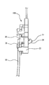
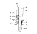
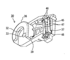
- FIG. 2 is a side view of the liquid level detection device viewed from the direction of arrow II in FIG. It is a top view of an insulator, It is a side view of an insulator, It is a perspective view of an insulator.
- the liquid level detection device 100 is installed in a fuel tank 90 that stores fuel as a liquid, as shown in FIG.
- the liquid level detection device 100 detects the height of the liquid level of the fuel stored in the fuel tank 90 while being held by the fuel pump module 93 or the like.
- the detection result detected by the liquid level detection device 100 is output from the connector 96 toward a combination meter (not shown), and is displayed to the driver by the combination meter.
- the liquid level detection device 100 includes a float 60, a float arm 50, an insulator 30, a housing 20, a circuit board 40, and a sliding plate 45.
- the float 60 is made of a material having a specific gravity smaller than that of a fuel such as foamed ebonite.
- the float 60 can float on the liquid surface of the fuel.
- the float 60 is held by the float arm 50.
- the float arm 50 is formed of a round bar-shaped core made of a conductive metal material such as stainless steel.
- the float arm 50 is formed with a float holding portion 53 and a rotating shaft 51.
- the float holding portion 53 is formed by bending the first end side of the float arm 50.
- the rotation shaft 51 is formed by bending the second end side of the float arm 50 in the direction along the rotation axis of the insulator 30 by about 90 degrees.
- the float arm 50 holds the float 60 by the float holding part 53 and is rotatably supported by the housing 20 by the rotating shaft 51.
- the float arm 50 configured as described above converts the vertical movement of the float 60 into the rotational motion of the insulator 30.
- the insulator 30 is formed of a resin material such as polyacetal (POM) resin.
- the insulator 30 is supported by the housing 20 so as to be relatively rotatable.
- a float arm 50 is attached to the insulator 30.
- the insulator 30 rotates relative to the housing 20 integrally with the float arm 50.
- one of the both surfaces of the insulator 30 formed in a plate shape that faces the circuit board 40 is referred to as a back surface, and the other located on the opposite side of the back surface is referred to as a front surface.
- the housing 20 shown in FIGS. 1 and 2 is formed of a resin material such as POM resin.
- the housing 20 is attached to the fuel pump module 93 and is fixed to the fuel tank 90 via the fuel pump module 93.
- a circuit board 40 and a plus terminal 71 and a minus terminal 74 connected to the circuit board 40 are attached to the housing 20.
- the housing 20 is formed in a container shape having a bottom wall and a side wall, and forms a board accommodating portion 28 that accommodates the circuit board 40.
- the housing 20 is formed with first and second terminal mounting portions 23 and 27, a cylindrical portion 26, and a substrate housing portion 28.
- the first and second terminal mounting portions 23 and 27 are formed on the side wall of the housing 20.
- a plus terminal 71 is fitted in the hole provided in the first terminal mounting portion 23.
- a minus terminal 74 is fitted in the hole provided in the second terminal mounting portion 27.
- the cylindrical portion 26 is formed in a cylindrical shape that penetrates the bottom wall of the housing 20.
- the cylindrical portion 26 shown in FIG. 5 rotatably supports the bearing surface 32 of the insulator 30 with a cylindrical outer peripheral wall.
- the cylindrical portion 26 rotatably supports the rotating shaft 51 of the float arm 50 by a cylindrical surface-shaped inner peripheral wall.
- the circuit board 40 shown in FIG. 1 is held by the housing 20 in a state of being housed in the board housing portion 28.
- a pair of resistor patterns 43 and 44 are formed on the circuit board 40 as a detection circuit 40a.
- Each of the resistor patterns 43 and 44 is formed on a surface located at a position close to the insulator 30 in the circuit board 40.
- Each of the resistor patterns 43 and 44 is formed in an arc shape around the rotation axis of the insulator 30.
- the first resistor pattern 43 is formed by arranging a plurality of resistors having a predetermined electric resistance value.
- the first resistor pattern 43 is an electrode pattern that becomes a positive electrode, and is electrically connected to the positive terminal 71.
- the second resistor pattern 44 is an electrode pattern that becomes a negative pole, and is electrically connected to the negative terminal 74. Thereby, a ground potential is applied to the second resistor pattern 44 via the connector 96.
- the sliding plate 45 is a plate-like member made of a metal material.
- the sliding plate 45 has conductivity. As shown in FIGS. 1 and 5, the sliding plate 45 is formed in a U shape as a whole.
- the sliding plate 45 has a base end portion 48, a flexible portion 47, and a sliding contact 46.
- the base end portion 48 is attached to the back surface of the insulator 30. Thereby, the sliding plate 45 rotates integrally with the insulator 30.
- a pair of the flexible portions 47 extends from the base end portion 48. Each flexible portion 47 can bend in the thickness direction of the sliding plate 45.
- the sliding contact 46 is provided at each distal end portion in the extending direction of each flexible portion 47. Each sliding contact 46 is pressed toward the resistor patterns 43 and 44 by the elasticity of the sliding plate 45.
- the detection circuit 40a and the sliding plate 45 in FIG. 1 form a variable resistor 41 in cooperation.
- the electric resistance value in the detection circuit 40 a changes according to the rotation angle of the insulator 30. Specifically, as shown in FIGS. 4 and 5, when the insulator 30 rotates, the sliding plate 45 fixed to the insulator 30 brings the sliding contacts 46 into contact with the resistor patterns 43 and 44. However, it is displaced relative to the circuit board 40. Thereby, each sliding contact 46 slides on each resistor pattern 43,44. When each sliding contact 46 is closest to each plus terminal 71 and minus 74, the electric resistance value of the detection circuit 40a is minimum.
- the electrical resistance of the detection circuit 40a gradually increases. Therefore, the rotation angle of the insulator 30 can be detected by the variable resistor 41.
- the combination meter connected to the detection circuit 40a can acquire the potential difference between the plus terminals 71 and minus 74 according to the electric resistance value of the detection circuit 40a as detection information of the liquid level.
- the insulator 30 is formed with a plate mounting portion 37, a fitting portion 36, an arm insertion hole 33, an arm locking claw 31, and an arm stopper 34.
- the plate mounting portion 37 is provided on the back surface of the insulator 30.
- the plate attachment portion 37 is formed at a position away from the arm insertion hole 33 in the insulator 30.
- a base end portion 48 is fixed to the plate attaching portion 37 by heat caulking or the like. With such a configuration, the plate mounting portion 37 holds the sliding plate 45.
- the fitting part 36 shown in FIG. 2 is externally fitted to the cylinder part 26 provided in the housing 20.
- the inner peripheral wall of the fitting portion 36 forms the bearing surface 32 described above.
- the bearing surface 32 is formed in a cylindrical surface shape. The bearing surface 32 slides with respect to the outer peripheral wall of the cylindrical portion 26 by the rotation of the insulator 30.
- the arm insertion hole 33 is a cylindrical hole that penetrates the insulator 30 in the plate thickness direction.
- the arm insertion hole 33 shown in FIG. 2 is located coaxially with the bearing surface 32 and the cylindrical portion 26.
- a rotation shaft 51 is inserted into the arm insertion hole 33 and the cylindrical portion 26.
- the inner peripheral wall of the arm insertion hole 33 fitted to the rotating shaft 51 is in close contact with the outer peripheral wall of the rotating shaft 51.
- Two arm locking claws 31 are provided on the front surface of the insulator 30. These arm locking claws 31 are arranged along the radial direction of the arm insertion hole 33.
- the arm locking claw 31 extends from the front surface and is curved in an arc shape. With such a shape, the end in the extending direction of the arm locking claw 31 is opposed to the front surface of the insulator 30.
- a gap formed between the tip of the arm locking claw 31 and the front surface of the insulator 30 is made smaller than the diameter of the float arm 50.
- the arm stopper 34 is formed so as to protrude from the front surface of the insulator 30.
- the arm stopper 34 can be displaced from the front surface side to the back surface side in the plate thickness direction of the insulator 30.
- the arm stopper 34 is positioned with respect to the arm locking claw 31 in each of the circumferential direction and the radial direction of the arm insertion hole 33.
- a float arm 50 is assembled to the insulator 30.
- the steps will be described in order.
- the rotating shaft 51 is inserted into the arm insertion hole 33.
- the arm stopper 34 is urged
- the float arm 50 is formed by the arm locking claws 31 by rotating the float arm 50 relative to the insulator 30 in a state where the insertion of the rotary shaft 51 into the arm insertion hole 33 is completed. It passes through the gap and is fitted into each arm locking claw 31.
- the contact surface 35 formed on the inner peripheral wall of the arm locking claw 31 is in a state of being pressed into contact with the float arm 50 by the elasticity of the arm locking claw 31. Further, the arm stopper 34 released from the urging force is displaced to the front surface side, thereby preventing the float arm 50 from being detached from the arm locking claw 31.
- a metal film 39 is formed on the insulator 30.
- the metal film 39 is a conductive film formed of a metal material.
- the metal film 39 is formed by metal plating applied to the insulator 30. Hereinafter, the plating process for plating the insulator 30 will be described in order.
- minute holes are formed on the outer surface of the resin material forming the insulator 30 by a process such as etching.
- a catalyst film is formed on the insulator 30 whose outer surface has been roughened in this way by a catalyst material having a strong reducing power, specifically, palladium-tin. Then, by removing tin from the catalyst coating, palladium is activated and the outer surface of the insulator 30 is made conductive. Electroplating is performed on the insulator 30 described above. Specifically, copper is first plated to form a base. Next, nickel is plated. Finally, the hardness of the metal film 39 is ensured by plating with chromium. By the above plating process, the metal film 39 covering the entire outer surface of the insulator 30 is formed.
- the metal film 39 thus formed covers each contact surface 35 that presses the float arm 50.
- the metal coating 39 covers the inner wall surface of the arm insertion hole 33 that fits into the rotating shaft 51. Therefore, conduction between the metal film 39 and the float arm 50 is reliably formed.
- the metal coating 39 covers the plate attachment portion 37 that holds the base end portion 48. Therefore, conduction between the metal film 39 and the sliding plate 45 is also reliably formed.
- the metal coating 39 can make the float arm 50 and the sliding plate 45 conductive.
- the resin material forming the insulator 30 may not have conductivity. Therefore, a standard resin material that has been proven to have high resistance to fuel, specifically, POM that does not contain carbon or has a low carbon content can be adopted as a material for the insulator 30. Become. Therefore, the liquid level detection apparatus 100 can acquire high reliability.
- the metal film 39 formed of a metal material such as nickel and chromium is very easy to conduct electricity. Therefore, continuity from the float arm 50 to the sliding plate 45 can be reliably ensured. Therefore, the charges generated in the float 60 can be surely released from the second resistor pattern 44 to the minus terminal 74.
- the contact surface 35 that specifically presses the float arm 50 among the arm locking claws 31 is covered with at least the metal film 39. Therefore, the metal coating 39 can maintain the state in which it is in reliable contact with the float arm 50 by the pressing force of the arm locking claw 31. Therefore, the conduction from the float arm 50 to the sliding plate 45 can be more reliable.
- the insulator 30 if the entire outer surface of the insulator 30 is covered with the metal film 39, the insulator 30 is protected by the metal film 39 and hardly exposed to the fuel. Therefore, the resin material forming the insulator 30 can maintain mechanical properties over a long period of time. Therefore, the liquid level detection apparatus 100 can obtain higher reliability.
- the housing 20 corresponds to a “support”
- the cylindrical portion 26 corresponds to a “support”
- the insulator 30 corresponds to a “rotator”.
- the arm locking claw 31 corresponds to a “locking claw”
- the bearing surface 32 corresponds to a “sliding surface”
- the contact surface 35 corresponds to “a region where the float arm is pressed”.
- the metal film 39 corresponds to a “conductive film”
- the detection circuit 40 a corresponds to a “variable resistance portion”
- the sliding plate 45 corresponds to a “conductive member”.
- the metal film is formed so as to avoid the bearing surface 32.
- the bearing surface 32 slides with respect to the cylindrical portion 26 as described above. Therefore, the metal film formed on the bearing surface 32 is easily peeled off. The peeled metal film may cause damage to the cylindrical portion 26 and the like. Therefore, in the first modification, the above-described fear can be solved by forming the metal film while avoiding the bearing surface 32. Therefore, the reliability of the liquid level detection device according to the modified example 1 becomes even more reliable.
- the metal film may not cover the entire outer surface of the insulator. If the metal film covers at least the contact surface 35 or the arm insertion hole 33 that contacts the float arm 50 and the plate mounting portion 37 that contacts the sliding plate 45, and these components 50 and 45 are electrically connected.
- the formation range may be changed as appropriate.
- the insulator 30 of the above embodiment is immersed in various liquids related to the formation of the coating film in the plating step after molding. Therefore, it is desirable that the branch-like surplus portion inevitably formed by a mold gate and liner at the time of molding is separated from the insulator 30 after the plating step. By holding the insulator 30 in such a surplus portion or the like, the process of immersing the insulator 30 in the liquid can be easily performed.
- the resin material which forms the insulator which was POM resin may be changed suitably, if mechanical properties, such as intensity
- the metal film 39 is formed by overlapping a plurality of types of metal plating.
- the configuration of the metal film is not limited to that of the above embodiment, and may be changed as appropriate.
- chrome plating may be applied to the base by copper plating by omitting nickel plating in the above embodiment.
- the metal film may be a single layer.
- the type of metal used for plating may be changed as appropriate.
- the “conductive film” is not limited to that formed by metal plating.
- the “conductive film” may be formed by applying a coating containing a metal to the outer surface of the insulator 30.
- the “conductive film” may not contain a metal material.
- the conductive film may be formed of a resin material containing carbon.
- the insulator 30 that functions as the “rotating body” has the “conductive film”.
- a “conductive film” is formed in a configuration that functions as a “rotating body”. May be.
- the “conductive film” having such a configuration is desirably conducted to a minus terminal or the like that transmits the output of the Hall IC.
- the present disclosure has been described based on an example in which the present disclosure is applied to a vehicle liquid level detection device that detects the remaining amount of fuel.
- the scope of application of the present disclosure need not be limited to such a liquid level detection device, but may be a liquid level detection device in a container of other liquids mounted on the vehicle, such as brake fluid, engine cooling water, and engine oil. May be.
- the present disclosure is applicable not only to vehicles but also to liquid level detection devices provided in liquid containers provided in various consumer devices and various transport machines.
Landscapes
- Physics & Mathematics (AREA)
- Fluid Mechanics (AREA)
- General Physics & Mathematics (AREA)
- Level Indicators Using A Float (AREA)
Abstract
液面検出装置(100)は、フロート(60)を保持する導電性のフロートアーム(50)と、フロートアームを保持するインシュレータ(30)と、インシュレータ(30)を回転可能に支持するハウジング(20)とを備えている。この液面検出装置(100)では、ハウジング(20)に固定された検出回路(40a)に対して、インシュレータ(30)に固定された摺動プレート(45)が摺動する。これにより、インシュレータ(30)の回転角度に応じて検出回路(40a)の電気抵抗値を変化させることができる。したがって、燃料の液面の高さが検出可能となる。そして、インシュレータ(30)には、フロートアーム(50)と摺動プレート(45)とを導通させる金属皮膜(39)が形成されている。故に、フロート(60)で生じた電荷を、検出回路(40a)に逃がすことが可能となる。
Description
本開示は、2013年3月6日に出願された日本出願番号2013-44507号に基づくもので、ここにその記載内容を援用する。
本開示は、液体の液面の高さを検出する液面検出装置に関する。
従来、特許文献1に開示のように、液面に浮かぶフロートを保持するフロートアームと、フロートアームを保持するアームホルダと、アームホルダを回転可能に支持するフレームとを備えた液面検出装置が知られている。特許文献1の液面検出装置では、抵抗体を有するセラミック基板がフレームに固定されると共に、導電性のプレートがアームホルダに固定されている。以上の構成では、フロートアームの回転によって抵抗体の表面をプレートが摺動すると、抵抗体の電気抵抗値が変化する。この電気抵抗値を計測することによれば、液面の高さの検出が可能となる。
特許文献1に開示のような液面検出装置のフロートには、液体との摩擦によって電荷が蓄積される。この電荷が導電性のフロートアームから抵抗体へと放電された場合、液面検出装置の検出精度は、低下してしまう。そこで、特許文献1では、アームホルダが、導電性の樹脂材料によって形成される。以上の構成であれば、フロートアームとプレートとの電気的な導通が確保される。故に、フロートに生じた電荷は、抵抗体に逃がされ得る。
しかし、特許文献1のアームホルダを形成する導電性樹脂は、カーボン等を添加されることにより、導電性を付与されている。こうしたカーボン等の添加に起因して、導電性の樹脂材料は、導電性を備えない標準的な樹脂材料と比較して、燃料等の液体に対する耐性が劣り易い。そのため、導電性樹脂によってアームホルダを形成してしまうと、液面検出装置の信頼性が不十分のおそれがある。
本開示は、上記事項に鑑みてなされたものであって、高い信頼性を備えた液面検出装置を提供することを目的とする。
本開示の一の態様において、液体の液面の高さを検出する液面検出装置であって、液面に浮かぶフロートを保持する導電性のフロートアームと、樹脂材料により形成され、フロートアームを保持する回転体と、回転体を回転可能に支持する支持体と、回転体に固定され、当該回転体の回転によって変位する導電性の導電部材と、支持体に固定され、導電部材を摺動させることで回転体の回転角度に応じて電気抵抗値を変化させる可変抵抗部と、を備え、回転体には、フロートアームと導電部材とを導通させる導電性の被膜が形成される。
この様態によると、フロートアームと導電部材との電気的な導通が、回転体に形成された導電性の被膜によって確保されている。故に、フロートに生じた電荷を、フロートアーム、導電性の被膜、及び導電部材を通じて、可変抵抗部に逃がすことができる。そして、導電性の被膜によって上述の導通が確保されることによれば、回転体を形成する樹脂材料は、導電性を備えていなくてもよい。よって、液体に対し高い耐性を有する樹脂材料が、回転体の材料として採用可能となる。したがって、液面検出装置は、高い信頼性を獲得できる。
本開示についての上記目的およびその他の目的、特徴や利点は、添付の図面を参照しながら下記の詳細な記述により、より明確になる。その図面は、
本開示の一実施形態による液面検出装置の正面図であり、
図1の矢印IIの方向から見た液面検出装置の側面図であり、
インシュレータの平面図であり、
インシュレータの側面図であり、
インシュレータの斜視図である。
以下、本開示の一実施形態を図面に基づいて説明する。
本開示の一実施形態による液面検出装置100は、図1に示すように、液体としての燃料を貯留する燃料タンク90内に設置されている。液面検出装置100は、燃料ポンプモジュール93等に保持された状態で、燃料タンク90に貯留されている燃料の液面の高さを検出する。液面検出装置100によって検出された検出結果は、コネクタ96からコンビネーションメータ(図示しない)に向けて出力され、コンビネーションメータによって運転者に表示される。
液面検出装置100は、フロート60、フロートアーム50、インシュレータ30、ハウジング20、回路基板40、及び摺動プレート45を備えている。
フロート60は、例えば発泡させたエボナイト等の燃料よりも比重の小さい材料により形成されている。フロート60は、燃料の液面に浮揚可能である。フロート60は、フロートアーム50に保持されている。
フロートアーム50は、ステンレス鋼等の導電性の金属材料からなる丸棒状の心材によって形成されている。フロートアーム50には、フロート保持部53及び回転軸51が形成されている。フロート保持部53は、フロートアーム50の第一端側を屈曲させることによって形成されている。回転軸51は、フロートアーム50の第二端側を、インシュレータ30の回転軸線に沿う方向に、90度程度屈曲させることによって形成されている。フロートアーム50は、フロート60をフロート保持部53にて保持し、回転軸51にてハウジング20に回転可能に支持されている。以上の構成によるフロートアーム50は、フロート60の上下移動をインシュレータ30の回転運動に変換する。
インシュレータ30は、例えばポリアセタール(POM)樹脂等の樹脂材料によって形成されている。インシュレータ30は、ハウジング20に相対回転可能に支持されている。インシュレータ30には、フロートアーム50が取り付けられている。インシュレータ30は、フロートアーム50と一体的にハウジング20に対して相対回転する。尚、以下の説明では、板状に形成されたインシュレータ30の両面のうち、回路基板40と対向する一方を裏面といい、この裏面とは反対側に位置する他方をおもて面という。
図1,2に示すハウジング20は、例えばPOM樹脂等の樹脂材料よって形成されている。ハウジング20は、燃料ポンプモジュール93に取り付けられており、当該燃料ポンプモジュール93を介して燃料タンク90に固定されている。ハウジング20には、回路基板40と、回路基板40に接続されたプラス端子71及びマイナス端子74とが、取り付けられている。ハウジング20は、底壁及び側壁を有する容器状に形成されており、回路基板40を収容する基板収容部28を形成している。ハウジング20には、第一、第二端子取付部23,27、及び筒部26、及び基板収容部28が形成されている。
第一、第二端子取付部23,27は、ハウジング20の側壁に形成されている。第一端子取付部23に設けられた孔部には、プラス端子71が嵌め込まれている。また、第二端子取付部27に設けられた孔部には、マイナス端子74が嵌め込まれている。筒部26は、ハウジング20の底壁を貫通する円筒状に形成されている。図5に示す筒部26は、円筒面状の外周壁によって、インシュレータ30の軸受面32を回転自在に支持している。加えて筒部26は、円筒面状の内周壁によって、フロートアーム50の回転軸51を回転自在に支持している。
図1に示す回路基板40は、基板収容部28に収容された状態で、ハウジング20に保持されている。回路基板40には、一組の抵抗体パターン43,44が、検出回路40aとして形成されている。各抵抗体パターン43,44は、回路基板40においてインシュレータ30に近い位置に位置する面に形成されている。各抵抗体パターン43,44は、インシュレータ30の回転軸を中心とした円弧状に形成されている。第一抵抗体パターン43は、所定の電気抵抗値を有する複数の抵抗体を配列することで形成されている。第一抵抗体パターン43は、プラス極となる電極パターンであって、プラス端子71と電気的に接続されている。第二抵抗体パターン44は、マイナス極となる電極パターンであって、マイナス端子74と電気的に接続されている。これにより、第二抵抗体パターン44には、コネクタ96を介して、グラウンド電位が印加される。
摺動プレート45は、金属材料によって形成された板状の部材である。摺動プレート45は、導電性を有している。摺動プレート45は、図1,5に示すように、全体としてU字状に形成されている。摺動プレート45は、基端部48、可撓部47、及び摺動接点46を有している。基端部48は、インシュレータ30の裏面に取り付けられている。これにより、摺動プレート45は、インシュレータ30と一体で回転する。可撓部47は、基端部48から一対延伸している。各可撓部47は、摺動プレート45の板厚方向に撓むことができる。摺動接点46は、各可撓部47の延伸方向における各先端部分に、それぞれ設けられている。各摺動接点46は、摺動プレート45の弾性により、各抵抗体パターン43,44に向けて押し付けられる。
図1の検出回路40a及び摺動プレート45は、協働で可変抵抗器41を形成している。検出回路40aにおける電気抵抗値は、インシュレータ30の回転角度に応じて変化する。詳記すると、図4,5に示すように、インシュレータ30が回転することにより、このインシュレータ30に固定された摺動プレート45は、各抵抗体パターン43,44に各摺動接点46を接触させつつ、回路基板40に対して相対的に変位する。これにより、各摺動接点46は、各抵抗体パターン43,44上を摺動する。各摺動接点46が各プラス端子71,マイナス74に最も近接している場合、検出回路40aの電気抵抗値は、最小となる。この状態からのインシュレータ30の回転によって各摺動接点46が各プラス端子71,マイナス74から遠ざかると、検出回路40aの電気的抵抗は、漸増する。よって、可変抵抗器41によるインシュレータ30の回転角度の検出が可能となる。そして、検出回路40aと接続されたコンビネーションメータは、検出回路40aの電気抵抗値に応じた各プラス端子71,マイナス74間の電位差を、液面の高さの検出情報として取得することができる。
次に、上述したインシュレータ30の詳細な構成について、図3~5に基づいてさらに説明する。
インシュレータ30には、プレート取付部37、嵌合部36、アーム挿入孔33、アーム係止爪31、及びアームストッパ34が形成されている。
プレート取付部37は、インシュレータ30の裏面に設けられている。プレート取付部37は、インシュレータ30において、アーム挿入孔33から離れた位置に形成されている。プレート取付部37には、基端部48が熱かしめ等によって固定されている。こうした構成により、プレート取付部37は、摺動プレート45を保持している。
図2に示す嵌合部36は、ハウジング20に設けられた筒部26に外嵌されている。嵌合部36の内周壁は、上述した軸受面32を形成している。軸受面32は、円筒面状に形成されている。軸受面32は、インシュレータ30の回転により、筒部26の外周壁に対して摺動する。
アーム挿入孔33は、インシュレータ30を板厚方向に貫通する円筒孔である。図2に示すアーム挿入孔33は、軸受面32及び筒部26と同軸上に位置している。アーム挿入孔33及び筒部26には、回転軸51が挿入される。回転軸51に嵌合したアーム挿入孔33の内周壁は、回転軸51の外周壁に密着する。
アーム係止爪31は、インシュレータ30のおもて面に、二つ設けられている。これらアーム係止爪31は、アーム挿入孔33の径方向に沿って並んでいる。アーム係止爪31は、おもて面から延伸し、円弧状に湾曲している。こうした形状により、アーム係止爪31における延伸方向の先端は、インシュレータ30のおもて面と対向している。アーム係止爪31の先端とインシュレータ30のおもて面との間に形成される隙間は、フロートアーム50の直径よりも小さくされている。
アームストッパ34は、インシュレータ30のおもて面から突出するように形成されている。アームストッパ34は、インシュレータ30の板厚方向において、おもて面側から裏面側へと変位することができる。アームストッパ34は、アーム挿入孔33の周方向及び径方向のそれぞれにおいて、アーム係止爪31に対し、ずれて位置している。
インシュレータ30には、図3に示すように、フロートアーム50が組み付けられる。その工程を順に説明すると、まず回転軸51がアーム挿入孔33に挿入される。これにより、アームストッパ34が、フロートアーム50によって付勢され、裏面側へと押し込まれる。そして、アーム挿入孔33への回転軸51の挿入が完了した状態下、インシュレータ30に対してフロートアーム50を相対回転させることにより、当該フロートアーム50は、各アーム係止爪31によって形成された隙間を通過して、各アーム係止爪31に嵌め込まれる。以上により、アーム係止爪31の内周壁に形成される接触面35が、当該アーム係止爪31の弾性により、フロートアーム50に押圧接触した状態となる。また、付勢力から解放されたアームストッパ34は、おもて面側へと変位することで、フロートアーム50のアーム係止爪31からの離脱を防止する。
さらに、インシュレータ30には、金属皮膜39が形成されている。金属皮膜39は、金属材料よって形成された導電性の被膜である。金属皮膜39は、インシュレータ30に施された金属メッキによって形成されている。以下、インシュレータ30にメッキを施すメッキ工程を順に説明する。
まず、インシュレータ30を形成する樹脂材料の外表面に、エッチング等の処理によって微小な穴が形成される。こうして外表面を粗化されたインシュレータ30に、還元力の強い触媒材料、具体的にはパラジウム-スズによって、触媒被膜が形成される。そして、触媒被膜からスズが除去されることにより、パラジウムが活性化されて、インシュレータ30の外表面が導電化される。以上のインシュレータ30に、電気メッキが行われる。具体的には、まず下地を形成するために、銅がメッキされる。次に、ニッケルがメッキされる。最後に、クロムがメッキされることにより、金属皮膜39の硬度が確保される。以上のメッキ工程により、インシュレータ30の外表面の全体を覆う金属皮膜39が形成される。
こうして形成された金属皮膜39は、フロートアーム50を押圧している各接触面35を被覆している。加えて金属皮膜39は、回転軸51に嵌合するアーム挿入孔33の内壁面を被覆している。故に、金属皮膜39とフロートアーム50との導通は、確実に形成される。加えて、金属皮膜39は、基端部48を保持するプレート取付部37を被覆している。故に、金属皮膜39と摺動プレート45との導通も、確実に形成される。これらにより、金属皮膜39は、フロートアーム50と摺動プレート45とを導通させることができる。
ここまで説明した本実施形態では、フロートアーム50と摺動プレート45との電気的な導通が、金属皮膜39によって確保されている。これにより、燃料からマイナス側の第二抵抗体パターン44に至る静電気の経路が形成される。よって、燃料との摩擦によってフロート60に生じた電荷は、フロートアーム50、金属皮膜39、及び摺動プレート45を通じて、第二抵抗体パターン44に移動し、マイナス端子74から外部へと逃がされ得る。
加えて、こうした導通が金属皮膜39によって確保されていれば、インシュレータ30を形成する樹脂材料は、導電性を備えていなくてもよい。よって、燃料に対し高い耐性を有することが実証済みである標準的な樹脂材料、具体的には、カーボンを含有しない、又はカーボンの含有量の少ないPOM等が、インシュレータ30の材料として採用可能となる。したがって、液面検出装置100は、高い信頼性を獲得できる。
加えて本実施形態のように、ニッケル及びクロム等の金属材料によって形成される金属皮膜39は、電気を非常に通し易い。故に、フロートアーム50から摺動プレート45までの導通は、確実に確保され得る。したがって、フロート60にて生じた電荷は、第二抵抗体パターン44からマイナス端子74へと確実に逃がされ得る。
また本実施形態では、アーム係止爪31のうちで、具体的に、フロートアーム50を押圧している接触面35が、少なくとも金属皮膜39によって覆われている。故に、金属皮膜39は、アーム係止爪31の押圧力によって、フロートアーム50と確実に接触した状態を維持し得る。よって、フロートアーム50から摺動プレート45までの導通は、いっそう確実なものとなり得る。
さらに本実施形態のように、インシュレータ30の外表面の全体を金属皮膜39で覆う形態であれば、このインシュレータ30は、金属皮膜39に保護されて、燃料に晒され難くなる。そのため、インシュレータ30を形成する樹脂材料は、長期に亘って機械的性質を維持し得る。したがって、液面検出装置100は、いっそう高い信頼性を獲得できる。
尚、本実施形態において、ハウジング20が「支持体」に相当し、筒部26が「支持部」に相当し、インシュレータ30が「回転体」に相当する。また、アーム係止爪31が「係止爪」に相当し、軸受面32が「摺動面」に相当し、接触面35が「フロートアームを押圧する領域」に相当する。そして、金属皮膜39が「導電性の被膜」に相当し、検出回路40aが「可変抵抗部」に相当し、摺動プレート45が「導電部材」に相当する。
(他の実施形態)
以上、本開示による一実施形態について説明したが、本開示は、上記実施形態に限定して解釈されるものではなく、本開示の要旨を逸脱しない範囲内において種々の実施形態及び組み合わせに適用することができる。
以上、本開示による一実施形態について説明したが、本開示は、上記実施形態に限定して解釈されるものではなく、本開示の要旨を逸脱しない範囲内において種々の実施形態及び組み合わせに適用することができる。
上記実施形態の変形例1では、金属皮膜は、軸受面32を避けて形成されている。軸受面32は、上述したように筒部26に対して摺動する。故に、軸受面32に形成された金属皮膜には、剥がれが生じ易くなる。そして、剥離した金属皮膜は、筒部26等の損傷を引き起こすおそれがある。故に、変形例1では、軸受面32を避けて金属被膜を形成することにより、上述のおそれが解消され得る。したがって、変形例1による液面検出装置の信頼性は、いっそう確かとなる。
また、上記変形例1のように、金属皮膜は、インシュレータの外表面全体を覆っていなくてもよい。金属皮膜は、フロートアーム50に接触する接触面35又はアーム挿入孔33と、摺動プレート45に接触するプレート取付部37とを少なくとも覆い、かつ、これらの構成50,45を導通させていれば、形成範囲を適宜変更されてよい。
上記実施形態のインシュレータ30は、成型後のメッキ工程において、被膜の形成に係る種々の液体に浸されることとなる。故に、成型時に金型のゲート及びライナー等にて不可避的に形成される枝状の余剰部分は、メッキ工程の後に、インシュレータ30から切り離されることが望ましい。こうした余剰部分等にインシュレータ30を保持させることにより、インシュレータ30を液体に浸す処理が、容易に実施できる。また、上記実施形態では、POM樹脂であったインシュレータを形成する樹脂材料は、強度等の機械的性質が確保されていれば、適宜変更されてよい。
上記実施形態では、複数種類の金属メッキが重ねられることにより、金属皮膜39は形成されていた。しかし、金属皮膜の構成は、上記実施形態のものに限定されず、適宜変更されてよい。例えば、上記実施形態におけるニッケルメッキが省略されることにより、銅メッキによる下地に、クロムメッキが施されてもよい。さらに金属皮膜は、単層であってもよい。また、メッキに用いられる金属の種類も、適宜変更されてよい。
さらに、の「導電性の被膜」は、金属メッキによって形成されるものに限定されない。例えば、金属を含む塗装がインシュレータ30の外表面に施されることにより、「導電性の被膜」が形成されていてもよい。さらに、「導電性の被膜」は、金属材料を含んでいなくてもよい。例えば、カーボンを含む樹脂材料によって、導電性の被膜が形成されていてもよい。
上記実施形態では、検出回路40aの電気抵抗値の変化に基づいて液面の高さを検出する形態の液面検出装置において、「回転体」として機能するインシュレータ30に、「導電性の被膜」が形成されていた。しかし、ホールICに作用する磁束密度の変化に基づいて液面の高さを検出する形態の液面検出装置において、「回転体」として機能する構成に、「導電性の被膜」が形成されていてもよい。こうした構成の「導電性の被膜」は、ホールICの出力を伝達するマイナス端子等に導通されていることが望ましい。
以上、本開示を燃料の残量を検出する車両用の液面検出装置に適用した例に基づいて説明した。しかし、本開示の適用対象は、こうした液面検出装置に限る必要はなく、車両に搭載される他の液体、例えばブレーキフルード、エンジン冷却水、エンジンオイル等の容器内の液面検出装置であってもよい。さらに、車両用に限らず、各種民生用機器、各種輸送機械が備える液体容器内に設けられる液面検出装置に、本開示は適用可能である。
本開示は、実施例に準拠して記述されたが、本開示は当該実施例や構造に限定されるものではないと理解される。本開示は、様々な変形例や均等範囲内の変形をも包含する。加えて、様々な組み合わせや形態、さらには、それらに一要素のみ、それ以上、あるいはそれ以下、を含む他の組み合わせや形態をも、本開示の範疇や思想範囲に入るものである。
Claims (5)
- 液体の液面の高さを検出する液面検出装置であって、
前記液面に浮かぶフロート(60)を保持する導電性のフロートアーム(50)と、
樹脂材料により形成され、前記フロートアームを保持する回転体(30)と、
前記回転体を回転可能に支持する支持体(20)と、
前記回転体に固定され、当該回転体の回転によって変位する導電性の導電部材(45)と、
前記支持体に固定され、前記導電部材を摺動させることで前記回転体の回転角度に応じて電気抵抗値を変化させる可変抵抗部(40a)と、を備え、
前記回転体には、前記フロートアームと前記導電部材とを導通させる導電性の被膜(39)が形成される液面検出装置。 - 前記被膜は、金属材料によって形成される請求項1に記載の液面検出装置。
- 前記回転体は、前記フロートアームを係止する係止爪(31)を有し、
前記被膜は、前記係止爪において前記フロートアームを押圧する領域(35)を、少なくとも覆う請求項1又は2に記載の液面検出装置。 - 前記被膜は、前記回転体の外表面の全体を覆っている請求項1~3のいずれか一項に記載の液面検出装置。
- 前記支持体は、前記回転体を回転自在に支持する支持部(26)を有し、
前記回転体は、前記支持部によって支持され、かつ、前記支持部に対して摺動する摺動面(32)を有し、
前記被膜は、前記摺動面を避けて形成される請求項1~3のいずれか一項に記載の液面検出装置。
Applications Claiming Priority (2)
| Application Number | Priority Date | Filing Date | Title |
|---|---|---|---|
| JP2013044507A JP5880879B2 (ja) | 2013-03-06 | 2013-03-06 | 液面検出装置 |
| JP2013-044507 | 2013-03-06 |
Publications (1)
| Publication Number | Publication Date |
|---|---|
| WO2014136383A1 true WO2014136383A1 (ja) | 2014-09-12 |
Family
ID=51490922
Family Applications (1)
| Application Number | Title | Priority Date | Filing Date |
|---|---|---|---|
| PCT/JP2014/000665 Ceased WO2014136383A1 (ja) | 2013-03-06 | 2014-02-07 | 液面検出装置 |
Country Status (2)
| Country | Link |
|---|---|
| JP (1) | JP5880879B2 (ja) |
| WO (1) | WO2014136383A1 (ja) |
Cited By (1)
| Publication number | Priority date | Publication date | Assignee | Title |
|---|---|---|---|---|
| CN111742198A (zh) * | 2018-02-22 | 2020-10-02 | 日本精机株式会社 | 液面检测装置 |
Families Citing this family (2)
| Publication number | Priority date | Publication date | Assignee | Title |
|---|---|---|---|---|
| JP6344222B2 (ja) * | 2014-12-04 | 2018-06-20 | 株式会社デンソー | 液面検出装置 |
| JP6344221B2 (ja) * | 2014-12-04 | 2018-06-20 | 株式会社デンソー | 液面検出装置 |
Citations (3)
| Publication number | Priority date | Publication date | Assignee | Title |
|---|---|---|---|---|
| JPS5536737A (en) * | 1978-09-08 | 1980-03-14 | Tokyo Tatsuno Co Ltd | Float for liquid-surface meter |
| JP2004340756A (ja) * | 2003-05-15 | 2004-12-02 | Denso Corp | 液面検出装置 |
| JP2012118044A (ja) * | 2010-11-08 | 2012-06-21 | Denso Corp | 液面検出装置 |
-
2013
- 2013-03-06 JP JP2013044507A patent/JP5880879B2/ja not_active Expired - Fee Related
-
2014
- 2014-02-07 WO PCT/JP2014/000665 patent/WO2014136383A1/ja not_active Ceased
Patent Citations (3)
| Publication number | Priority date | Publication date | Assignee | Title |
|---|---|---|---|---|
| JPS5536737A (en) * | 1978-09-08 | 1980-03-14 | Tokyo Tatsuno Co Ltd | Float for liquid-surface meter |
| JP2004340756A (ja) * | 2003-05-15 | 2004-12-02 | Denso Corp | 液面検出装置 |
| JP2012118044A (ja) * | 2010-11-08 | 2012-06-21 | Denso Corp | 液面検出装置 |
Cited By (2)
| Publication number | Priority date | Publication date | Assignee | Title |
|---|---|---|---|---|
| CN111742198A (zh) * | 2018-02-22 | 2020-10-02 | 日本精机株式会社 | 液面检测装置 |
| CN111742198B (zh) * | 2018-02-22 | 2023-11-17 | 日本精机株式会社 | 液面检测装置 |
Also Published As
| Publication number | Publication date |
|---|---|
| JP5880879B2 (ja) | 2016-03-09 |
| JP2014173894A (ja) | 2014-09-22 |
Similar Documents
| Publication | Publication Date | Title |
|---|---|---|
| JP5310798B2 (ja) | 液面検出装置 | |
| CN102365534B (zh) | 液面检测装置 | |
| CN104024812B (zh) | 液面检测装置 | |
| JP5880879B2 (ja) | 液面検出装置 | |
| CN102639976A (zh) | 液面检测装置 | |
| JP3941735B2 (ja) | 液面検出装置 | |
| JP5494091B2 (ja) | 液面検出装置の製造方法 | |
| US9677925B2 (en) | Liquid level detection device and manufacturing method of liquid level detection device | |
| US10317268B2 (en) | Liquid level detection device | |
| JP2011141146A (ja) | 液面検出装置とその製造方法 | |
| US20070085532A1 (en) | Fuel level gauge for use in automobile | |
| HUP0700825A2 (en) | Casing for in-tank hall effect sensor used for fuel level sensing | |
| KR101343313B1 (ko) | 연료 유량검출장치 | |
| JP2010175425A (ja) | 液面検出装置 | |
| JP2007240274A (ja) | 液面検出装置 | |
| US10323976B2 (en) | Liquid level detection device | |
| JP4957644B2 (ja) | 液面検出装置 | |
| JP2017116361A (ja) | 液面検出装置 | |
| JP5206574B2 (ja) | 液面検出装置 | |
| JP6344226B2 (ja) | 液面検出装置 | |
| JP5494084B2 (ja) | 液面検出装置の製造方法 | |
| JP2018031698A (ja) | 液面検出装置 | |
| JP2017150852A (ja) | 液面検出装置 | |
| JP2011133279A (ja) | 液面検出装置 | |
| JP2016125819A (ja) | 液面検出装置 |
Legal Events
| Date | Code | Title | Description |
|---|---|---|---|
| 121 | Ep: the epo has been informed by wipo that ep was designated in this application |
Ref document number: 14759860 Country of ref document: EP Kind code of ref document: A1 |
|
| NENP | Non-entry into the national phase |
Ref country code: DE |
|
| 122 | Ep: pct application non-entry in european phase |
Ref document number: 14759860 Country of ref document: EP Kind code of ref document: A1 |