WO2014133275A1 - 이차 전지 및 그 제조 방법 - Google Patents
이차 전지 및 그 제조 방법 Download PDFInfo
- Publication number
- WO2014133275A1 WO2014133275A1 PCT/KR2014/001232 KR2014001232W WO2014133275A1 WO 2014133275 A1 WO2014133275 A1 WO 2014133275A1 KR 2014001232 W KR2014001232 W KR 2014001232W WO 2014133275 A1 WO2014133275 A1 WO 2014133275A1
- Authority
- WO
- WIPO (PCT)
- Prior art keywords
- electrode assembly
- secondary battery
- sealing member
- safety vent
- assembly
- Prior art date
Links
- 238000004519 manufacturing process Methods 0.000 title claims abstract description 18
- 238000007789 sealing Methods 0.000 claims abstract description 61
- 239000003792 electrolyte Substances 0.000 claims abstract description 10
- 230000000903 blocking effect Effects 0.000 claims description 22
- 238000000034 method Methods 0.000 claims description 22
- 238000003466 welding Methods 0.000 claims description 20
- 230000008878 coupling Effects 0.000 claims description 18
- 238000010168 coupling process Methods 0.000 claims description 18
- 238000005859 coupling reaction Methods 0.000 claims description 18
- 239000011324 bead Substances 0.000 claims description 4
- 235000015250 liver sausages Nutrition 0.000 abstract 1
- 239000007789 gas Substances 0.000 description 9
- 239000000463 material Substances 0.000 description 6
- WHXSMMKQMYFTQS-UHFFFAOYSA-N Lithium Chemical compound [Li] WHXSMMKQMYFTQS-UHFFFAOYSA-N 0.000 description 5
- 229910052744 lithium Inorganic materials 0.000 description 5
- 238000002788 crimping Methods 0.000 description 4
- 230000008569 process Effects 0.000 description 4
- 229910052782 aluminium Inorganic materials 0.000 description 3
- XAGFODPZIPBFFR-UHFFFAOYSA-N aluminium Chemical compound [Al] XAGFODPZIPBFFR-UHFFFAOYSA-N 0.000 description 3
- 238000010292 electrical insulation Methods 0.000 description 3
- 229910052751 metal Inorganic materials 0.000 description 3
- 239000002184 metal Substances 0.000 description 3
- 239000007769 metal material Substances 0.000 description 3
- 239000002002 slurry Substances 0.000 description 3
- 239000004743 Polypropylene Substances 0.000 description 2
- 239000011149 active material Substances 0.000 description 2
- 239000011248 coating agent Substances 0.000 description 2
- 238000000576 coating method Methods 0.000 description 2
- 239000008151 electrolyte solution Substances 0.000 description 2
- 235000015110 jellies Nutrition 0.000 description 2
- 239000008274 jelly Substances 0.000 description 2
- 238000012986 modification Methods 0.000 description 2
- 230000004048 modification Effects 0.000 description 2
- 239000007773 negative electrode material Substances 0.000 description 2
- 229920001155 polypropylene Polymers 0.000 description 2
- 239000007774 positive electrode material Substances 0.000 description 2
- 239000010935 stainless steel Substances 0.000 description 2
- 229910001220 stainless steel Inorganic materials 0.000 description 2
- 238000003860 storage Methods 0.000 description 2
- 240000001973 Ficus microcarpa Species 0.000 description 1
- 229910045601 alloy Inorganic materials 0.000 description 1
- 239000000956 alloy Substances 0.000 description 1
- 239000011230 binding agent Substances 0.000 description 1
- OJIJEKBXJYRIBZ-UHFFFAOYSA-N cadmium nickel Chemical compound [Ni].[Cd] OJIJEKBXJYRIBZ-UHFFFAOYSA-N 0.000 description 1
- 239000003575 carbonaceous material Substances 0.000 description 1
- 239000004020 conductor Substances 0.000 description 1
- 238000007599 discharging Methods 0.000 description 1
- 230000005611 electricity Effects 0.000 description 1
- 238000010438 heat treatment Methods 0.000 description 1
- 229910052739 hydrogen Inorganic materials 0.000 description 1
- 239000001257 hydrogen Substances 0.000 description 1
- 238000003780 insertion Methods 0.000 description 1
- 230000037431 insertion Effects 0.000 description 1
- 238000009413 insulation Methods 0.000 description 1
- 238000005304 joining Methods 0.000 description 1
- 239000005022 packaging material Substances 0.000 description 1
- 239000004014 plasticizer Substances 0.000 description 1
- 229920000098 polyolefin Polymers 0.000 description 1
- -1 polypropylene Polymers 0.000 description 1
- 239000002904 solvent Substances 0.000 description 1
- 238000003756 stirring Methods 0.000 description 1
- 239000013585 weight reducing agent Substances 0.000 description 1
Images


Classifications
-
- H—ELECTRICITY
- H01—ELECTRIC ELEMENTS
- H01M—PROCESSES OR MEANS, e.g. BATTERIES, FOR THE DIRECT CONVERSION OF CHEMICAL ENERGY INTO ELECTRICAL ENERGY
- H01M10/00—Secondary cells; Manufacture thereof
- H01M10/05—Accumulators with non-aqueous electrolyte
- H01M10/058—Construction or manufacture
-
- H—ELECTRICITY
- H01—ELECTRIC ELEMENTS
- H01M—PROCESSES OR MEANS, e.g. BATTERIES, FOR THE DIRECT CONVERSION OF CHEMICAL ENERGY INTO ELECTRICAL ENERGY
- H01M10/00—Secondary cells; Manufacture thereof
- H01M10/05—Accumulators with non-aqueous electrolyte
- H01M10/052—Li-accumulators
-
- H—ELECTRICITY
- H01—ELECTRIC ELEMENTS
- H01M—PROCESSES OR MEANS, e.g. BATTERIES, FOR THE DIRECT CONVERSION OF CHEMICAL ENERGY INTO ELECTRICAL ENERGY
- H01M50/00—Constructional details or processes of manufacture of the non-active parts of electrochemical cells other than fuel cells, e.g. hybrid cells
- H01M50/10—Primary casings; Jackets or wrappings
- H01M50/102—Primary casings; Jackets or wrappings characterised by their shape or physical structure
- H01M50/107—Primary casings; Jackets or wrappings characterised by their shape or physical structure having curved cross-section, e.g. round or elliptic
-
- H—ELECTRICITY
- H01—ELECTRIC ELEMENTS
- H01M—PROCESSES OR MEANS, e.g. BATTERIES, FOR THE DIRECT CONVERSION OF CHEMICAL ENERGY INTO ELECTRICAL ENERGY
- H01M50/00—Constructional details or processes of manufacture of the non-active parts of electrochemical cells other than fuel cells, e.g. hybrid cells
- H01M50/10—Primary casings; Jackets or wrappings
- H01M50/147—Lids or covers
- H01M50/148—Lids or covers characterised by their shape
- H01M50/152—Lids or covers characterised by their shape for cells having curved cross-section, e.g. round or elliptic
-
- H—ELECTRICITY
- H01—ELECTRIC ELEMENTS
- H01M—PROCESSES OR MEANS, e.g. BATTERIES, FOR THE DIRECT CONVERSION OF CHEMICAL ENERGY INTO ELECTRICAL ENERGY
- H01M50/00—Constructional details or processes of manufacture of the non-active parts of electrochemical cells other than fuel cells, e.g. hybrid cells
- H01M50/10—Primary casings; Jackets or wrappings
- H01M50/147—Lids or covers
- H01M50/166—Lids or covers characterised by the methods of assembling casings with lids
- H01M50/169—Lids or covers characterised by the methods of assembling casings with lids by welding, brazing or soldering
-
- H—ELECTRICITY
- H01—ELECTRIC ELEMENTS
- H01M—PROCESSES OR MEANS, e.g. BATTERIES, FOR THE DIRECT CONVERSION OF CHEMICAL ENERGY INTO ELECTRICAL ENERGY
- H01M50/00—Constructional details or processes of manufacture of the non-active parts of electrochemical cells other than fuel cells, e.g. hybrid cells
- H01M50/10—Primary casings; Jackets or wrappings
- H01M50/183—Sealing members
- H01M50/186—Sealing members characterised by the disposition of the sealing members
-
- H—ELECTRICITY
- H01—ELECTRIC ELEMENTS
- H01M—PROCESSES OR MEANS, e.g. BATTERIES, FOR THE DIRECT CONVERSION OF CHEMICAL ENERGY INTO ELECTRICAL ENERGY
- H01M50/00—Constructional details or processes of manufacture of the non-active parts of electrochemical cells other than fuel cells, e.g. hybrid cells
- H01M50/30—Arrangements for facilitating escape of gases
- H01M50/317—Re-sealable arrangements
- H01M50/325—Re-sealable arrangements comprising deformable valve members, e.g. elastic or flexible valve members
-
- H—ELECTRICITY
- H01—ELECTRIC ELEMENTS
- H01M—PROCESSES OR MEANS, e.g. BATTERIES, FOR THE DIRECT CONVERSION OF CHEMICAL ENERGY INTO ELECTRICAL ENERGY
- H01M50/00—Constructional details or processes of manufacture of the non-active parts of electrochemical cells other than fuel cells, e.g. hybrid cells
- H01M50/30—Arrangements for facilitating escape of gases
- H01M50/342—Non-re-sealable arrangements
- H01M50/3425—Non-re-sealable arrangements in the form of rupturable membranes or weakened parts, e.g. pierced with the aid of a sharp member
-
- H—ELECTRICITY
- H01—ELECTRIC ELEMENTS
- H01M—PROCESSES OR MEANS, e.g. BATTERIES, FOR THE DIRECT CONVERSION OF CHEMICAL ENERGY INTO ELECTRICAL ENERGY
- H01M50/00—Constructional details or processes of manufacture of the non-active parts of electrochemical cells other than fuel cells, e.g. hybrid cells
- H01M50/50—Current conducting connections for cells or batteries
- H01M50/543—Terminals
- H01M50/545—Terminals formed by the casing of the cells
-
- H—ELECTRICITY
- H01—ELECTRIC ELEMENTS
- H01M—PROCESSES OR MEANS, e.g. BATTERIES, FOR THE DIRECT CONVERSION OF CHEMICAL ENERGY INTO ELECTRICAL ENERGY
- H01M50/00—Constructional details or processes of manufacture of the non-active parts of electrochemical cells other than fuel cells, e.g. hybrid cells
- H01M50/50—Current conducting connections for cells or batteries
- H01M50/572—Means for preventing undesired use or discharge
- H01M50/574—Devices or arrangements for the interruption of current
- H01M50/578—Devices or arrangements for the interruption of current in response to pressure
-
- H—ELECTRICITY
- H01—ELECTRIC ELEMENTS
- H01M—PROCESSES OR MEANS, e.g. BATTERIES, FOR THE DIRECT CONVERSION OF CHEMICAL ENERGY INTO ELECTRICAL ENERGY
- H01M50/00—Constructional details or processes of manufacture of the non-active parts of electrochemical cells other than fuel cells, e.g. hybrid cells
- H01M50/50—Current conducting connections for cells or batteries
- H01M50/572—Means for preventing undesired use or discharge
- H01M50/574—Devices or arrangements for the interruption of current
- H01M50/581—Devices or arrangements for the interruption of current in response to temperature
-
- H—ELECTRICITY
- H01—ELECTRIC ELEMENTS
- H01M—PROCESSES OR MEANS, e.g. BATTERIES, FOR THE DIRECT CONVERSION OF CHEMICAL ENERGY INTO ELECTRICAL ENERGY
- H01M2200/00—Safety devices for primary or secondary batteries
- H01M2200/10—Temperature sensitive devices
- H01M2200/106—PTC
-
- Y—GENERAL TAGGING OF NEW TECHNOLOGICAL DEVELOPMENTS; GENERAL TAGGING OF CROSS-SECTIONAL TECHNOLOGIES SPANNING OVER SEVERAL SECTIONS OF THE IPC; TECHNICAL SUBJECTS COVERED BY FORMER USPC CROSS-REFERENCE ART COLLECTIONS [XRACs] AND DIGESTS
- Y02—TECHNOLOGIES OR APPLICATIONS FOR MITIGATION OR ADAPTATION AGAINST CLIMATE CHANGE
- Y02E—REDUCTION OF GREENHOUSE GAS [GHG] EMISSIONS, RELATED TO ENERGY GENERATION, TRANSMISSION OR DISTRIBUTION
- Y02E60/00—Enabling technologies; Technologies with a potential or indirect contribution to GHG emissions mitigation
- Y02E60/10—Energy storage using batteries
-
- Y—GENERAL TAGGING OF NEW TECHNOLOGICAL DEVELOPMENTS; GENERAL TAGGING OF CROSS-SECTIONAL TECHNOLOGIES SPANNING OVER SEVERAL SECTIONS OF THE IPC; TECHNICAL SUBJECTS COVERED BY FORMER USPC CROSS-REFERENCE ART COLLECTIONS [XRACs] AND DIGESTS
- Y02—TECHNOLOGIES OR APPLICATIONS FOR MITIGATION OR ADAPTATION AGAINST CLIMATE CHANGE
- Y02P—CLIMATE CHANGE MITIGATION TECHNOLOGIES IN THE PRODUCTION OR PROCESSING OF GOODS
- Y02P70/00—Climate change mitigation technologies in the production process for final industrial or consumer products
- Y02P70/50—Manufacturing or production processes characterised by the final manufactured product
-
- Y—GENERAL TAGGING OF NEW TECHNOLOGICAL DEVELOPMENTS; GENERAL TAGGING OF CROSS-SECTIONAL TECHNOLOGIES SPANNING OVER SEVERAL SECTIONS OF THE IPC; TECHNICAL SUBJECTS COVERED BY FORMER USPC CROSS-REFERENCE ART COLLECTIONS [XRACs] AND DIGESTS
- Y10—TECHNICAL SUBJECTS COVERED BY FORMER USPC
- Y10T—TECHNICAL SUBJECTS COVERED BY FORMER US CLASSIFICATION
- Y10T29/00—Metal working
- Y10T29/49—Method of mechanical manufacture
- Y10T29/49002—Electrical device making
- Y10T29/49108—Electric battery cell making
- Y10T29/4911—Electric battery cell making including sealing
Definitions
- the present invention relates to a technique for manufacturing a secondary battery, and more particularly, to a secondary battery and a method of manufacturing the same having improved capacity and safety by preventing welding of the cap assembly and the battery case without forming a bead portion.
- a secondary battery unlike a primary battery that cannot be charged, means a battery that can be charged and discharged, and is widely used in electronic devices such as mobile phones, notebook computers, camcorders, and electric vehicles.
- the lithium secondary battery has an operating voltage of about 3.6V, and has about three times the capacity of a nickel-cadmium battery or a nickel-hydrogen battery, which is widely used as a power source for electronic equipment, and has a high energy density per unit weight. The degree is increasing rapidly.
- Such lithium secondary batteries mainly use lithium-based oxides and carbon materials as positive electrode active materials and negative electrode active materials, respectively.
- the lithium secondary battery includes an electrode assembly in which a positive electrode plate and a negative electrode plate coated with such a positive electrode active material and a negative electrode active material are disposed with a separator interposed therebetween, and a battery case (external material) for sealingly storing the electrode assembly together with the electrolyte solution.
- the lithium secondary battery may be classified into a can type secondary battery in which an electrode assembly is embedded in a metal can and a pouch type secondary battery in which an electrode assembly is embedded in a pouch of an aluminum laminate sheet according to the type of battery case.
- the can-type secondary battery may be further classified into a cylindrical battery and a square battery according to the shape of the metal can.
- the rectangular or cylindrical secondary battery packaging material includes a battery case having an open end and a cap assembly sealingly coupled to the open end of the battery case.
- FIG. 1 is a schematic cross-sectional view of a conventional cylindrical secondary battery in which a beading portion is formed in a battery case.
- a cylindrical secondary battery generally includes a cylindrical battery case 20 sealed at a lower end thereof and an open upper end thereof, a jelly-roll electrode assembly 30 accommodated inside the battery case 20, and a battery case.
- the cap assembly 10 coupled to the upper portion of the 20, the beading portion 40 provided at the tip of the battery case 20 for mounting the cap assembly 10, and the crimping portion 50 for sealing the battery are provided. Equipped.
- the electrode assembly 30 is typically a structure in which a separator is sandwiched between a positive electrode plate and a negative electrode plate in a jelly-roll shape, and a positive electrode lead 31 is attached to the positive electrode plate and connected to the cap assembly 10.
- the negative lead 32 is attached to the lower end of the battery case 20.
- the cap assembly 10 includes a top cap 11 that forms a positive terminal, a safety vent 12 that blocks current when the pressure rises inside the cell and / or exhausts gas, and a safety vent 12 except for a specific portion.
- the insulating member 13 for electrically separating the current blocking member 15 from the current blocking member 15 and the current blocking member 14 to which the positive electrode lead 31 connected to the positive electrode plate is connected are sequentially stacked.
- the cap assembly 10 is mounted to the beading part 40 of the battery case 20 while being mounted on the gasket 15. Therefore, under normal operating conditions, the anode of the electrode assembly 30 is connected to the top cap 11 via the anode lead 31, the current blocking member 14, and the safety vent 12 to conduct electricity.
- the beading portion 40 should be formed in the battery case 20 in order to couple and fix the cap assembly 10. Since the storage capacity of the electrode assembly 30 is reduced by the portion, there is a problem that the battery capacity is eventually reduced. Therefore, in order to solve this problem, a secondary battery in which the beading portion 40 is not formed in the battery case 20 has recently been proposed.
- FIG. 2 is a schematic cross-sectional view of a conventional cylindrical secondary battery in which no beading portion is formed in the battery case 20.
- the beading part is not formed in the battery case 20.
- the cap assembly 10 is coupled at the top of the battery case 20, such as a portion indicated by L, by laser welding or the like to seal the battery case 20.
- the cover 16 is typically provided at the outermost portion of the cap assembly 10. Since the cover 16 is a component for welding the battery case 20, the cover 16 may be made of a material that can be welded with the battery case 20, for example, a metal material.
- cap assembly 10 heat may be generated during welding of the cap assembly 10 and the battery case 20, which may damage various components of the cap assembly 10.
- the cap assembly 10 since the cap assembly 10 must be separately provided with a cover 16 made of a material such as metal for welding with the battery case 20, the structure of the cap assembly 10 may be more complicated and manufacturing costs may increase. And, the weight of the secondary battery can be increased.
- An object of the present invention is to provide a secondary battery capable of preventing damage and improving productivity and a method of manufacturing the same.
- a secondary battery according to the present invention for achieving the above object is a secondary battery that does not have a beading portion, the electrode assembly having a positive electrode plate and a negative electrode plate disposed between the separator;
- a battery case accommodating the electrode assembly and the electrolyte in an inner space, the battery case including an upper can and an open bottom and an upper can bent in an inward direction and a lower sealing member coupled to a lower end of the upper can to seal a lower end thereof;
- a top cap disposed protruding from the top to form a positive electrode terminal, a safety vent that is deformed when the internal pressure of the battery case increases in a lower portion of the top cap, and a gasket surrounding edges of the top cap and the safety vent. It includes a cap assembly comprising a.
- the gasket has an upper end contacting an inner surface of an upper bent portion of the upper can and a lower end contacting an upper surface of the electrode assembly.
- the gasket has an upper end contacting an inner surface of an upper bent portion of the upper can, and a lower end contacting an upper surface of the upper insulating plate.
- the upper can and the lower sealing member are coupled by laser welding.
- the lower sealing member is provided with a groove, and the upper can is inserted into the groove of the lower sealing member.
- the battery pack according to the present invention for achieving the above object includes the above-described secondary battery.
- a secondary battery manufacturing method for achieving the above object, a method for manufacturing a secondary battery without a beading portion, comprising the steps of preparing an electrode assembly, the positive electrode plate and the negative electrode plate disposed between the separator; Preparing a battery case including an upper space is formed in the inner space to accommodate the electrode assembly and the electrolyte, and the upper and lower ends are bent in the inward direction and the lower sealing member separated from the upper can; A top cap disposed protruding from the top to form a positive electrode terminal, a safety vent that is deformed when the internal pressure of the battery case increases from a lower portion of the top cap, and a gasket surrounding edges of the top cap and the safety vent Preparing a cap assembly comprising a; Inserting the cap assembly upwardly through the lower opening of the upper can such that the upper end of the gasket contacts the bent upper inner surface of the upper can; Inserting the electrode assembly in an upward direction through the lower opening of the upper can to be positioned below the cap assembly; And
- the step of inserting the electrode assembly the electrode assembly is inserted such that the upper surface of the electrode assembly is in contact with the lower end of the gasket.
- the preparing of the electrode assembly may further include an upper insulating plate on the upper part of the electrode assembly, and the inserting of the electrode assembly may include the electrode assembly such that an upper surface of the upper insulating plate contacts the lower end of the gasket. Insert
- the lower sealing member is coupled to the lower end of the upper can by laser welding.
- the upper can is inserted into the groove of the lower sealing member.
- the storage space of the electrode assembly is increased, the capacity of the secondary battery can be improved.
- the battery case and the cap assembly are not welded, it is possible to prevent the short from occurring in the secondary battery due to the welding residue generated during the welding.
- heat generated during the welding process can be transferred to the cap assembly to prevent damage to the cap assembly.
- the cap assembly since the cap assembly does not need to include a cover for welding the battery case separately, this can prevent the structure of the cap assembly from being complicated and reduce manufacturing cost and time.
- the productivity and quality of the secondary battery can be improved, and the weight reduction of the secondary battery can be easily achieved.
- FIG. 1 is a schematic cross-sectional view of a conventional cylindrical secondary battery in which a beading portion is formed in a battery case.
- FIG. 2 is a schematic cross-sectional view of a conventional cylindrical secondary battery in which no beading portion is formed in the battery case.
- FIG 3 is a cross-sectional view schematically showing the configuration of a secondary battery according to an embodiment of the present invention.
- FIG. 4 is a view schematically showing a coupling configuration of an upper can and a lower sealing member according to an embodiment of the present invention.
- FIG 5 and 6 are views schematically showing a coupling configuration of the upper can and the lower sealing member according to another embodiment of the present invention.
- FIG. 7 is a view schematically showing a coupling configuration of an upper can and a lower sealing member according to still another embodiment of the present invention.
- FIG. 8 is a flowchart schematically illustrating a method of manufacturing a secondary battery in which the beading portion is not formed according to an embodiment of the present invention.
- FIG 3 is a cross-sectional view schematically showing the configuration of a secondary battery according to an embodiment of the present invention.
- the secondary battery according to the present invention includes an electrode assembly 300, a battery case 200, and a cap assembly 100.
- the electrode assembly 300 may have a form in which a positive electrode plate and a negative electrode plate are disposed with a separator interposed therebetween and accommodated in the battery case 200.
- the electrode assembly 300 may be wound and disposed in the form of a jelly roll, in which case it is also called a jelly roll.
- the electrode plates of the electrode assembly 300 are formed as a structure in which an active material slurry is applied to a current collector, and the slurry may be formed by stirring a granular active material, an auxiliary conductor, a binder, a plasticizer, and the like in a state where a solvent is added. .
- the electrode plates In the direction in which the electrode plates are wound, there may be a non-coating portion in which the slurry is not coated at the beginning and the end of the current collector, and an electrode lead corresponding to each electrode plate may be attached to the non-coating portion.
- the anode lead 310 is attached to the top of the electrode assembly 300 to be electrically connected to the cap assembly 100
- the cathode lead 320 is attached to the bottom of the electrode assembly 300 to be connected to the battery case 200. Is connected to the bottom of the.
- the battery case 200 may be made of a lightweight conductive metal material such as aluminum, stainless steel, or an alloy thereof, and may have an internal space formed therein to accommodate the electrode assembly 300 and the electrolyte in the internal space.
- the battery case 200 may be composed of an upper can 210 and a lower sealing member 220.
- the upper can 210 constitutes an upper portion and a side portion of the battery case 200 as a configuration that occupies most of the battery case 200, and provides an inner space for accommodating the electrode assembly 300 and the electrolyte.
- the upper and lower ends of the upper can 210 are open. Accordingly, the upper portion of the cap assembly 100 may be exposed to the outside of the secondary battery through the upper opening of the upper can 210 to be electrically connected to the external device.
- the top opening of the upper can 210 has a size such that the cap assembly 100 and the electrode assembly 300 cannot pass, while the bottom opening of the upper can 210 has the cap assembly 100 and the electrode.
- the assembly 300 is sized enough to pass through. Therefore, the cap assembly 100 and the electrode assembly 300 may be inserted into the battery case 200 through the lower opening of the upper can 210.
- the upper end of the upper can 210 may be bent in the inner direction. That is, the upper can 210 may have a bent portion 211 at an upper end thereof.
- the upper bent portion 211 may prevent the cap assembly 100 from escaping in the upper direction of the upper can 210.
- the upper bent portion 211 of the upper can 210 is not formed after inserting the electrode assembly 300 and the cap assembly 100 into the battery case 200 like the conventional crimping portion of the secondary battery.
- the electrode assembly 300 and the cap assembly 100 are preformed before insertion. Therefore, there is no fear that the electrode assembly 300 or the cap assembly 100 may be damaged in the conventional crimping process for forming the crimping portion.
- the upper can 210 may be formed in a cylindrical shape. Therefore, the secondary battery according to the present invention can be applied to a cylindrical secondary battery.
- the present invention is not necessarily limited by the specific shape of the upper can 210, the upper can 210 may be formed in a shape other than a cylindrical shape, such as a rectangular cylinder.
- the lower sealing member 220 is coupled to the lower end of the upper can 210 serves to seal the lower end of the battery case 200. That is, in the secondary battery according to the present invention, the lower end of the upper can 210 is open, and the lower sealing member 220 is coupled to the lower end of the upper can 210 to prevent the lower opening. Therefore, the lower sealing member 220 may prevent the electrode assembly 300 and the electrolyte solution contained in the upper can 210 from leaking through the lower end of the upper can 210.
- the lower sealing member 220 is coupled to the upper can 210 after the cap assembly 100 and the electrode assembly 300 are inserted into the inner space of the upper can 210 through the lower opening.
- the electrolyte is injected through the lower end of the upper can 210 after the cap assembly 100 and the electrode assembly 300 are inserted and before the lower sealing member 220 is coupled with the upper can 210.
- the electrolyte may be inserted into the upper can 210 through the cap assembly 100 after the lower sealing member 220 is combined with the upper can 210.
- the upper can 210 and the lower sealing member 220 may be coupled by laser welding.
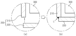
- FIG. 4 is a view schematically showing a coupling configuration of the upper can 210 and the lower sealing member 220 according to an embodiment of the present invention.
- FIG. 4 for convenience of description, the portion A of FIG. 3 will be mainly described.
- the lower end of the upper can 210 is open, and the lower sealing member 220 of the upper can 210 is inserted after the electrode assembly 300 is inserted. Will move to the bottom.
- the lower sealing member 220 is in close contact with the lower end of the upper can 210, as indicated by L in FIG. 4B, the lower end of the upper can 210 and the lower sealing member 220 are laser welded. These parts can be sealed by being joined to each other through a joining method such as.
- FIG. 4 illustrates the configuration of the lower left side of the battery case 200 of FIG. 3, but the coupling of the shape may be performed on the entire bottom of the battery case.
- the coupling form of the upper can 210 and the lower sealing member 220 shown in Figure 4 is only one example, the present invention is not necessarily limited to this coupling form, there may be a variety of coupling forms.
- the lower sealing member 220 is provided with a groove, and the upper can 210 is inserted into the groove of the lower sealing member 220, whereby the upper can 210 and the lower sealing member 220 are formed. Can be combined.
- FIGS. 5 and 6 are views schematically showing a coupling configuration of the upper can 210 and the lower sealing member 220 according to another embodiment of the present invention.
- FIGS. 5 and 6 for convenience of description, parts corresponding to part A of FIG. 3 will be mainly described.
- the lower sealing member 220 may have a groove 221, that is, a concave portion formed thereon.
- the groove 221 may be formed in a shape corresponding to the lower end of the upper can 210. Therefore, as indicated by the arrow in FIG. 5, when the lower sealing member 220 moves to the lower end of the upper can 210 to be in close contact, the lower end of the upper can 210 may be inserted into the groove 221. have.
- the groove 221 of the lower sealing member 220 may be formed in various ways.
- the inside of the protrusion 222 becomes a concave portion, such a portion may also be called a groove. . Therefore, as indicated by the arrows in FIG. 6, when the lower sealing member 220 moves to the lower end of the upper can 210 and is in close contact with each other, the lower end of the upper can 210 inside the groove, that is, the protrusion 222. You can let it be located.
- the upper can 210 and the lower sealing member 220 may be laser welded to each other. Can be.
- FIG. 7 is a view schematically showing a coupling configuration of the upper can 210 and the lower sealing member 220 according to another embodiment of the present invention.
- the lower sealing member 220 may be configured to be inserted into the lower inner surface of the upper can 210.
- the lower sealing member 220 and the upper can 210 may be bonded to each other by laser welding as indicated by L.
- the cap assembly 100 includes a top cap 110, a safety vent 120, and a gasket 150.
- the cap assembly 100 may be formed in various shapes, such as a circle or a square, according to the shape of the battery case 200.
- the top cap 110 is disposed in a shape protruding upward in the uppermost portion of the cap assembly 100 to form a positive electrode terminal.
- the top cap 110 allows the secondary battery to be electrically connected to the outside.
- a gas hole through which gas may be discharged may be formed in the top cap 110. Therefore, when gas is generated from the electrode assembly 300, the gas may be discharged to the outside of the battery case 200 through the gas hole.
- the top cap 110 may be formed of a metal material such as stainless steel or aluminum, for example.
- the safety vent 120 may be disposed such that the top cap 110 and the outer circumferential surface thereof, that is, the edge portion, contact the lower portion of the top cap 110.
- the safety vent 120 is configured to be deformed when the internal pressure of the secondary battery, that is, the internal pressure of the battery case 200 increases to a predetermined level or more.
- the safety vent 120 may be configured to deform and rupture when the internal pressure of the secondary battery is 12-25 kgf / cm 2 .
- the safety vent 120 as shown in the figure, the center portion is formed to protrude in the downward direction, a predetermined notch may be formed near the center. Therefore, when gas is generated from the inside of the secondary battery, that is, the electrode assembly 300, and the internal pressure increases, the safety vent 120 protrudes upward while its shape is reversed, and may be ruptured around the notches. . Therefore, the gas that has been filled inside the battery case 200 may be discharged to the outside through the ruptured portion of the safety vent 120.
- the gasket 150 is configured to surround the edges of the top cap 110 and the safety vent 120.
- the gasket 150 may be interposed between the upper can 210, the top cap 110, and the safety vent 120.
- the gasket 150 may be formed of a material having electrical insulation since the top cap 110 and the edge of the safety vent 120 may be insulated from the upper can 210.
- the gasket 150 may be made of a material having impact resistance, elasticity, and durability to support and protect the cap assembly 100.
- the gasket 150 may be made of, for example, polyolefine or polypropylene (PP).
- PP polypropylene
- the gasket 150 may be bent by mechanical processing rather than by heat treatment in order to prevent electrical insulation from being weakened.
- the gasket 150 may include a protrusion 151 supporting the lower edge of the safety vent 120 in an upward direction.
- the protrusion 151 of the gasket 150 may prevent the safety vent 120 and the top cap 110 from escaping downward.
- the gasket 150 may not include the protrusion 151, and in this case, the top cap 110 and the safety vent 120 may be supported upward through a bent form.
- the gasket 150 may be configured such that the lower end portion contacts the upper surface of the electrode assembly 300, as indicated in part B of FIG. 3.
- the gasket 150 may be configured such that an upper end thereof contacts the inner surface of the upper bent part 211 of the upper can 210. According to this embodiment, it is possible to prevent the electrode assembly 300 from flowing in the battery case 200, in particular, the electrode assembly 300 flows up and down by the gasket 150.
- the secondary battery according to the present invention may further include an upper insulating plate on the electrode assembly 300.
- the upper insulating plate is made of a material having electrical insulation, and may serve to insulate the electrode assembly 300 and the cap assembly 100.
- the gasket 150 may be configured such that a lower end thereof contacts the upper surface of the upper insulating plate. In addition, the gasket 150 may prevent the flow of the electrode assembly 300 by contacting the upper end portion with the inner surface of the upper bent portion 211 of the upper can 210.
- the cap assembly 100 of the secondary battery according to the present invention may further include a current blocking member 140, as shown in FIG.
- the current interrupting member 140 also called a CID (Current Interrupt Device) is located between the safety vent 120 and the electrode assembly 300, so that the electrode assembly 300 and the safety vent 120 are electrically connected. do. That is, at least a portion of the upper portion of the current blocking member 140 is connected to the lower end of the central protruding portion of the safety vent 120, and the lower portion thereof is connected to the electrode lead of the electrode assembly 300, such as the anode lead 310. Therefore, in the normal state, the current generated from the electrode assembly 300 flows through the anode lead 310 to the current blocking member 140, the safety vent 120, and the top cap 110, thereby discharging the secondary battery. have.
- CID Current Interrupt Device
- the cap assembly 100 may include the current blocking member 140.
- the cap assembly 100 may further include an insulating member 130.
- the insulating member 130 is interposed between the safety vent 120 and the current blocking member 140, except for a portion where the central protruding portion of the safety vent 120 is in contact with the current blocking member 140.
- the blocking member 140 and the safety vent 120 are electrically insulated from each other.
- the shape of the cap assembly 100 shown in FIG. 3 is only one embodiment, and the present invention is not limited to the specific shape of the cap assembly 100.
- the cap assembly 100 of the secondary battery according to the present invention may further include a safety device (not shown).
- the safety device is disposed between the top cap 110 and the safety vent 120 to electrically connect the top cap 110 and the safety vent 120.
- a safety device may block a current flow inside the battery when the temperature of the secondary battery increases, for example, it may be formed of a positive temperature coefficient element (PTC) device.
- PTC positive temperature coefficient element
- the battery pack according to the present invention includes at least one secondary battery described above.
- the battery pack may include a battery management device such as a battery management system (BMS) to control the charge / discharge operation.
- BMS battery management system
- FIG. 8 is a flowchart schematically illustrating a method of manufacturing a secondary battery in which the beading portion is not formed according to an embodiment of the present invention.
- an electrode assembly 300 having a positive electrode plate and a negative electrode plate disposed therebetween is prepared (S110), and an upper can 210 and a lower sealing member.
- a battery case 200 including the 220 is prepared (S120).
- the cap assembly 100 including the top cap 110, the safety vent 120, and the gasket 150 is also prepared (S130).
- the upper can 210 has an internal space is formed to accommodate the electrode assembly 300 and the electrolyte, the top and bottom are open, especially the top It is bent inward.
- the lower sealing member 220 of the battery case 200 is provided in a state separate from the upper can 210.
- the upper can 210 may be cylindrical, but the present invention is not necessarily limited to the shape of the upper can 210.
- the top cap 110 is disposed in a form protruding on the top of the secondary battery to form a positive electrode terminal, the safety vent 120 of the top cap 110 The shape is changed when the internal pressure of the battery case 200 increases in the lower portion, and the gasket 150 is configured to surround the edges of the top cap 110 and the safety vent 120.
- steps S110, S120, and S130 are illustrated as being sequentially performed, but this is for convenience of description only, and steps S110, S120, and S130 may be reversed. It may be performed at the same time.
- the cap assembly eg, the upper end of the gasket 150 is in contact with the bent upper inner surface of the upper can 210.
- 100 is inserted through the lower opening of the upper can 210 (S140).
- the electrode assembly 300 is inserted into the upper can 210 through the lower opening of the upper can 210 so as to be positioned below the cap assembly 100 (S150).
- the lower sealing member 220 is coupled to the lower end of the upper can 210 so that the lower opening of the upper can 210 can be sealed (S160).
- the electrode assembly 300 may be inserted such that the upper surface of the electrode assembly 300 contacts the lower end of the gasket 150.
- the upper insulating plate may be further provided on the upper part of the electrode assembly 300.
- the electrode assembly (the upper surface of the upper insulating plate is in contact with the lower end of the gasket 150). It is preferred to insert 300).
- the step S160 may be performed such that the lower sealing member 220 is coupled to the lower end of the upper can 210 by laser welding.
- the step S160 may be performed in a form in which the upper can 210 is inserted into a groove of the lower sealing member 220.
- the battery case 200 having a groove formed in the lower sealing member 220 may be prepared so that the lower end of the upper can 210 may be inserted.
- the step S130 may include a current blocking member 140 and a safety vent 120 and a current blocking member having an upper portion connected to a lower end of the safety vent 120 and a lower portion connected to the electrode assembly 300.
- the cap assembly 100 may further include an insulation member 130 interposed between the portions 140 to electrically insulate the current blocking member 140 from the safety vent 120 except for a portion thereof.
- the step S130 may be disposed between the top cap 110 and the safety vent 120 to further include a safety element in the cap assembly 100 to block a current when the temperature rises.
Landscapes
- Chemical & Material Sciences (AREA)
- Chemical Kinetics & Catalysis (AREA)
- Electrochemistry (AREA)
- General Chemical & Material Sciences (AREA)
- Engineering & Computer Science (AREA)
- Manufacturing & Machinery (AREA)
- Sealing Battery Cases Or Jackets (AREA)
- Secondary Cells (AREA)
- Connection Of Batteries Or Terminals (AREA)
- Gas Exhaust Devices For Batteries (AREA)
Abstract
Description
Claims (17)
- 비딩부가 형성되지 않은 이차 전지에 있어서,양극판 및 음극판이 세퍼레이터를 사이에 두고 배치된 전극 조립체;내부 공간에 상기 전극 조립체 및 전해액을 수납하고 상단 및 하단이 개방되어 있으며 상단이 내측 방향으로 절곡된 상부 캔 및 상기 상부 캔의 하단에 결합되어 하단을 밀폐시키는 하부 밀폐부재를 포함하는 전지 케이스; 및최상부에 돌출된 형태로 배치되어 양극 단자를 형성하는 탑 캡, 상기 탑 캡의 하부에서 상기 전지 케이스의 내압 증가시 형태가 변형되는 안전 벤트, 및 상기 탑 캡 및 상기 안전 벤트의 테두리들을 감싸는 가스켓을 포함하는 캡 조립체를 포함하는 것을 특징으로 하는 이차 전지.
- 제1항에 있어서,상기 가스켓은, 상단부가 상기 상부 캔의 상단 절곡부 내면에 접촉되고, 하단부가 상기 전극 조립체의 상면에 접촉되는 것을 특징으로 하는 이차 전지.
- 제1항에 있어서,상기 전극 조립체의 상부에 상부 절연판을 더 포함하고,상기 가스켓은, 상단부가 상기 상부 캔의 상단 절곡부 내면에 접촉되고, 하단부가 상기 상부 절연판의 상면에 접촉되는 것을 특징으로 하는 이차 전지.
- 제1항에 있어서,상기 상부 캔과 상기 하부 밀폐부재는, 레이저 용접에 의해 결합된 것을 특징으로 하는 이차 전지.
- 제1항에 있어서,상기 하부 밀폐부재는 홈이 형성되어 있고, 상기 상부 캔은 상기 하부 밀폐부재의 홈에 삽입되는 것을 특징으로 하는 이차 전지.
- 제1항에 있어서,상부가 상기 안전 벤트의 하단에 연결되고, 하부가 전극 조립체와 연결될 수 있는 전류차단부재; 및 상기 안전 벤트와 상기 전류차단부재 사이에 개재되어 일부분을 제외하고는 상기 전류차단부재를 상기 안전 벤트와 전기적으로 절연시키는 절연부재를 더 포함하는 것을 특징으로 하는 이차 전지.
- 제1항에 있어서,상기 탑 캡과 상기 안전 벤트 사이에 배치되어, 온도 상승시 전류를 차단하는 안전 소자를 더 포함하는 것을 특징으로 하는 이차 전지.
- 제1항에 있어서,상기 상부 캔은, 원통형으로 형성된 것을 특징으로 하는 이차 전지.
- 제1항 내지 제8항 중 어느 한 항에 따른 이차 전지를 포함하는 배터리 팩.
- 비딩부가 형성되지 않은 이차 전지를 제조하는 방법에 있어서,양극판 및 음극판이 세퍼레이터를 사이에 두고 배치된 전극 조립체를 준비하는 단계;상기 전극 조립체 및 전해액을 수납 가능하도록 내부 공간이 형성되고 상단 및 하단이 개방되어 상단이 내측 방향으로 절곡된 상부 캔 및 상기 상부 캔과 분리된 하부 밀폐부재를 포함하는 전지 케이스를 준비하는 단계;상기 최상부에 돌출된 형태로 배치되어 양극 단자를 형성하는 탑 캡, 상기 탑 캡의 하부에서 상기 전지 케이스의 내압 증가시 형태가 변형되는 안전 벤트, 및 상기 탑 캡 및 상기 안전 벤트의 테두리들을 감싸는 가스켓을 포함하는 캡 조립체를 준비하는 단계;상기 가스켓의 상단부가 상기 상부 캔의 절곡된 상부 내면에 접촉되도록 상기 캡 조립체를 상기 상부 캔의 하단 개방부를 통하여 상부 방향으로 삽입하는 단계;상기 캡 조립체의 하부에 위치하도록 상기 전극 조립체를 상기 상부 캔의 하단 개방부를 통하여 상부 방향으로 삽입하는 단계; 및상기 상부 캔의 하단을 밀폐시키도록 상기 하부 밀폐부재를 상기 상부 캔의 하단에 결합하는 단계를 포함하는 것을 특징으로 하는 이차 전지 제조 방법.
- 제10항에 있어서,상기 전극 조립체의 삽입 단계는, 상기 전극 조립체의 상면이 상기 가스켓의 하단부에 접촉되도록 상기 전극 조립체를 삽입하는 것을 특징으로 하는 이차 전지 제조 방법.
- 제10항에 있어서,상기 전극 조립체의 준비 단계는, 상기 전극 조립체의 상부에 상부 절연판을 더 구비하고,상기 전극 조립체의 삽입 단계는, 상기 상부 절연판의 상면이 상기 가스켓의 하단부에 접촉되도록 상기 전극 조립체를 삽입하는 것을 특징으로 하는 이차 전지 제조 방법.
- 제10항에 있어서,상기 하부 밀폐부재와 상부 캔의 결합 단계에서, 상기 하부 밀폐부재는 레이저 용접에 의해 상기 상부 캔의 하단에 결합되는 것을 특징으로 하는 이차 전지 제조 방법.
- 제10항에 있어서,상기 하부 밀폐부재와 상부 캔의 결합 단계에서, 상기 상부 캔은 상기 하부 밀폐부재의 홈에 삽입되는 것을 특징으로 하는 이차 전지 제조 방법.
- 제10항에 있어서,상기 캡 조립체의 준비 단계는, 상기 캡 조립체에 상부가 상기 안전 벤트의 하단에 연결되고, 하부가 전극 조립체와 연결될 수 있는 전류차단부재 및 상기 안전 벤트와 상기 전류차단부재 사이에 개재되어 일부분을 제외하고는 상기 전류차단부재를 상기 안전 벤트와 전기적으로 절연시키는 절연부재가 더 포함되도록 하는 것을 특징으로 하는 이차 전지 제조 방법.
- 제10항에 있어서,상기 캡 조립체의 준비 단계는, 상기 캡 조립체에 상기 탑 캡과 상기 안전 벤트 사이에 배치되어, 온도 상승시 전류를 차단하는 안전 소자가 더 포함되도록 하는 것을 특징으로 하는 이차 전지 제조 방법.
- 제10항에 있어서,상기 상부 캔은, 원통형인 것을 특징으로 하는 이차 전지 제조 방법.
Priority Applications (4)
| Application Number | Priority Date | Filing Date | Title |
|---|---|---|---|
| JP2015534405A JP6022696B2 (ja) | 2013-02-26 | 2014-02-14 | 二次電池及びその製造方法 |
| EP14757062.6A EP2822060B1 (en) | 2013-02-26 | 2014-02-14 | Secondary battery and manufacturing method therefor |
| CN201480001073.0A CN104285314B (zh) | 2013-02-26 | 2014-02-14 | 二次电池和用于制造二次电池的方法 |
| US14/491,023 US9843025B2 (en) | 2013-02-26 | 2014-09-19 | Secondary battery and method for manufacturing the same |
Applications Claiming Priority (2)
| Application Number | Priority Date | Filing Date | Title |
|---|---|---|---|
| KR10-2013-0020744 | 2013-02-26 | ||
| KR1020130020744A KR101514827B1 (ko) | 2013-02-26 | 2013-02-26 | 이차 전지 및 그 제조 방법 |
Related Child Applications (1)
| Application Number | Title | Priority Date | Filing Date |
|---|---|---|---|
| US14/491,023 Continuation US9843025B2 (en) | 2013-02-26 | 2014-09-19 | Secondary battery and method for manufacturing the same |
Publications (1)
| Publication Number | Publication Date |
|---|---|
| WO2014133275A1 true WO2014133275A1 (ko) | 2014-09-04 |
Family
ID=51428495
Family Applications (1)
| Application Number | Title | Priority Date | Filing Date |
|---|---|---|---|
| PCT/KR2014/001232 WO2014133275A1 (ko) | 2013-02-26 | 2014-02-14 | 이차 전지 및 그 제조 방법 |
Country Status (7)
| Country | Link |
|---|---|
| US (1) | US9843025B2 (ko) |
| EP (1) | EP2822060B1 (ko) |
| JP (1) | JP6022696B2 (ko) |
| KR (1) | KR101514827B1 (ko) |
| CN (1) | CN104285314B (ko) |
| TW (1) | TWI489676B (ko) |
| WO (1) | WO2014133275A1 (ko) |
Families Citing this family (25)
| Publication number | Priority date | Publication date | Assignee | Title |
|---|---|---|---|---|
| JP6490053B2 (ja) * | 2014-03-28 | 2019-03-27 | 三洋電機株式会社 | 円筒形密閉電池及び電池パック |
| US10340483B2 (en) | 2014-08-26 | 2019-07-02 | Cps Technology Holdings Llc | Welding process for sealing a battery module |
| KR102567831B1 (ko) | 2015-10-02 | 2023-08-17 | 삼성에스디아이 주식회사 | 이차 전지 |
| KR20180075797A (ko) * | 2016-12-27 | 2018-07-05 | 주식회사 엘지화학 | 전기절연성 소재에 의해 전류차단부재와 안전벤트가 결합되어 있는 원통형 전지셀의 캡 어셈블리 |
| KR102263435B1 (ko) * | 2017-09-13 | 2021-06-11 | 주식회사 엘지에너지솔루션 | 비딩부가 생략된 원통형 전지셀 |
| KR102275779B1 (ko) | 2017-11-17 | 2021-07-13 | 주식회사 엘지에너지솔루션 | 이차전지 |
| EP3726622A4 (en) | 2017-12-13 | 2021-06-16 | Samsung SDI Co., Ltd. | SECONDARY BATTERY |
| CN117254223A (zh) * | 2018-01-03 | 2023-12-19 | 宁德时代新能源科技股份有限公司 | 二次电池及汽车 |
| JP7093199B2 (ja) * | 2018-02-16 | 2022-06-29 | Fdk株式会社 | 封口体及び電池 |
| CN111919308A (zh) * | 2018-04-06 | 2020-11-10 | 三洋电机株式会社 | 电池 |
| US11881550B2 (en) | 2018-04-06 | 2024-01-23 | Panasonic Energy Co., Ltd. | Battery |
| EP3780135A4 (en) * | 2018-04-06 | 2021-04-28 | SANYO Electric Co., Ltd. | DRUMS |
| CN111954940A (zh) * | 2018-04-06 | 2020-11-17 | 三洋电机株式会社 | 电池 |
| KR102323809B1 (ko) | 2018-06-18 | 2021-11-09 | 주식회사 엘지에너지솔루션 | 벤팅 장치 및 그의 제조 방법 |
| US10804515B2 (en) * | 2018-08-08 | 2020-10-13 | Duracell U.S. Operations, Inc. | Batteries having vents |
| CN109860448A (zh) * | 2019-01-03 | 2019-06-07 | 王生义 | 一种用于电池的帽盖组件以及电池 |
| CN110880564A (zh) * | 2019-10-28 | 2020-03-13 | 宜兴市惠华复合材料有限公司 | 一种新型锂电池外壳以及应用该外壳的壳盖 |
| JPWO2021182080A1 (ko) * | 2020-03-09 | 2021-09-16 | ||
| US20240128608A1 (en) * | 2021-02-19 | 2024-04-18 | Lg Energy Solution, Ltd. | Battery, and battery pack and vehicle comprising the same |
| CN113328213B (zh) * | 2021-04-27 | 2023-07-11 | 宁波超霸能源有限公司 | 圆柱型锂电池的制作方法 |
| CN113675510B (zh) * | 2021-08-17 | 2023-01-24 | 厦门海辰储能科技股份有限公司 | 电芯的端部连接结构、电芯、动力电池 |
| DE102022101673A1 (de) * | 2022-01-25 | 2023-07-27 | Bayerische Motoren Werke Aktiengesellschaft | Batteriezellgehäuse für eine Batteriezelle eines elektrischen Energiespeichers sowie Batteriezelle |
| SE2251010A1 (en) * | 2022-08-31 | 2023-09-18 | Northvolt Ab | A cylindrical secondary cell comprising an enclosure with a brim and a lid with a flange |
| SE2251008A1 (en) * | 2022-08-31 | 2023-09-18 | Northvolt Ab | A cylindrical secondary cell comprising a reduced radius enclosure and a lid |
| SE2251011A1 (en) * | 2022-08-31 | 2023-09-18 | Northvolt Ab | A cylindrical secondary cell comprising an inclined enclosure and a lid |
Citations (5)
| Publication number | Priority date | Publication date | Assignee | Title |
|---|---|---|---|---|
| KR20060097481A (ko) * | 2005-03-09 | 2006-09-14 | 삼성에스디아이 주식회사 | 원통형 이차 전지 및 그 형성 방법 |
| KR20090089292A (ko) * | 2006-09-29 | 2009-08-21 | 쉔젠 비에이케이 배터리 컴퍼니 리미티드 | 배터리 코어 케이스 및 배터리 |
| KR20120063264A (ko) * | 2010-12-07 | 2012-06-15 | 주식회사 엘지화학 | 캡 조립체 및 이를 이용한 이차 전지 |
| US8252455B2 (en) * | 2009-05-25 | 2012-08-28 | Toyota Jidosha Kabushiki Kaisha | Battery pack, vehicle equipped with the battery pack, and device equipped with the battery pack |
| WO2013025078A2 (ko) * | 2011-08-18 | 2013-02-21 | 주식회사 엘지화학 | 이차 전지 제조 방법 |
Family Cites Families (29)
| Publication number | Priority date | Publication date | Assignee | Title |
|---|---|---|---|---|
| JPS578619Y2 (ko) * | 1976-09-14 | 1982-02-18 | ||
| JPS5341622A (en) | 1976-09-27 | 1978-04-15 | Honda Motor Co Ltd | Piston made of fiber-reinforced light alloy |
| JPS54144222U (ko) * | 1978-03-31 | 1979-10-06 | ||
| JPS54144222A (en) | 1978-04-28 | 1979-11-10 | Iwasaki Kosei | Pusheddout writing implement |
| US5626983A (en) * | 1994-07-13 | 1997-05-06 | Rayovac Corporation | Zinc anode for reduced environmental hazard LeClanche cell having improved performance |
| CA2131777A1 (en) * | 1994-09-09 | 1996-03-10 | Allen Shkuratoff | Sealed electrical device with unitary fill port and terminal construction |
| JPH11283586A (ja) * | 1998-03-31 | 1999-10-15 | Sanyo Electric Co Ltd | 電池とその製造方法 |
| US6265096B1 (en) * | 1998-08-21 | 2001-07-24 | Eveready Battery Company, Inc. | Electrochemical cell having collector electrically insulated from cover |
| US6410186B1 (en) * | 1998-08-21 | 2002-06-25 | Eveready Battery Company, Inc. | Battery construction having double seam cover closure |
| JP2003142043A (ja) * | 2001-07-09 | 2003-05-16 | Hitachi Maxell Ltd | 電 池 |
| US7070881B2 (en) * | 2001-10-18 | 2006-07-04 | Quallion Llc | Electrical battery assembly and method of manufacture |
| JP2004071265A (ja) * | 2002-08-05 | 2004-03-04 | Sanyo Electric Co Ltd | 電池 |
| JP4356314B2 (ja) * | 2002-12-20 | 2009-11-04 | パナソニック株式会社 | 電池及び組電池 |
| JP4567374B2 (ja) * | 2003-08-28 | 2010-10-20 | パナソニック株式会社 | 電池およびその製造方法 |
| TWI318016B (en) * | 2003-12-09 | 2009-12-01 | Hon Hai Prec Ind Co Ltd | Cap assembly for nonaqueous electrolyte battery |
| JP5198723B2 (ja) * | 2005-06-13 | 2013-05-15 | 冨士発條株式会社 | 密閉型電池用封口板 |
| JP2007179793A (ja) * | 2005-12-27 | 2007-07-12 | Denso Corp | 密閉型電池用蓋体 |
| JP2010511992A (ja) * | 2006-12-05 | 2010-04-15 | ファン,インヨン | 円筒形二次電池及びその製造方法 |
| CN101257099A (zh) * | 2007-03-02 | 2008-09-03 | 深圳市比克电池有限公司 | 电池封口组件及电池 |
| CN101257098B (zh) * | 2007-03-02 | 2012-01-25 | 深圳市比克电池有限公司 | 便于装配的电池封口组件及电池 |
| JP5264099B2 (ja) * | 2007-04-12 | 2013-08-14 | パナソニック株式会社 | 非水電解質二次電池 |
| JP2009181776A (ja) * | 2008-01-30 | 2009-08-13 | Toyota Motor Corp | 密閉型電池 |
| KR100917742B1 (ko) * | 2008-03-13 | 2009-09-15 | 삼성에스디아이 주식회사 | 원통형 이차전지 |
| JP4446205B2 (ja) * | 2008-04-14 | 2010-04-07 | トヨタ自動車株式会社 | 電池およびその製造方法 |
| JP2009289637A (ja) * | 2008-05-30 | 2009-12-10 | Toyota Motor Corp | 密閉型電池及びその製造方法 |
| KR101097255B1 (ko) * | 2009-11-30 | 2011-12-21 | 삼성에스디아이 주식회사 | 이차 전지 |
| KR20110066448A (ko) * | 2009-12-11 | 2011-06-17 | 삼성에스디아이 주식회사 | 리튬 이차전지 |
| KR101184403B1 (ko) * | 2010-10-21 | 2012-09-19 | 주식회사 엘지화학 | 캡 조립체 및 이를 이용한 이차 전지 |
| US8501333B2 (en) | 2010-10-21 | 2013-08-06 | Lg Chem, Ltd. | Cap assembly and secondary battery using the same |
-
2013
- 2013-02-26 KR KR1020130020744A patent/KR101514827B1/ko active IP Right Grant
-
2014
- 2014-02-14 EP EP14757062.6A patent/EP2822060B1/en active Active
- 2014-02-14 JP JP2015534405A patent/JP6022696B2/ja active Active
- 2014-02-14 CN CN201480001073.0A patent/CN104285314B/zh active Active
- 2014-02-14 WO PCT/KR2014/001232 patent/WO2014133275A1/ko active Application Filing
- 2014-02-24 TW TW103106065A patent/TWI489676B/zh active
- 2014-09-19 US US14/491,023 patent/US9843025B2/en active Active
Patent Citations (5)
| Publication number | Priority date | Publication date | Assignee | Title |
|---|---|---|---|---|
| KR20060097481A (ko) * | 2005-03-09 | 2006-09-14 | 삼성에스디아이 주식회사 | 원통형 이차 전지 및 그 형성 방법 |
| KR20090089292A (ko) * | 2006-09-29 | 2009-08-21 | 쉔젠 비에이케이 배터리 컴퍼니 리미티드 | 배터리 코어 케이스 및 배터리 |
| US8252455B2 (en) * | 2009-05-25 | 2012-08-28 | Toyota Jidosha Kabushiki Kaisha | Battery pack, vehicle equipped with the battery pack, and device equipped with the battery pack |
| KR20120063264A (ko) * | 2010-12-07 | 2012-06-15 | 주식회사 엘지화학 | 캡 조립체 및 이를 이용한 이차 전지 |
| WO2013025078A2 (ko) * | 2011-08-18 | 2013-02-21 | 주식회사 엘지화학 | 이차 전지 제조 방법 |
Non-Patent Citations (1)
| Title |
|---|
| See also references of EP2822060A4 * |
Also Published As
| Publication number | Publication date |
|---|---|
| CN104285314A (zh) | 2015-01-14 |
| TW201503467A (zh) | 2015-01-16 |
| EP2822060A1 (en) | 2015-01-07 |
| KR101514827B1 (ko) | 2015-04-23 |
| CN104285314B (zh) | 2017-02-22 |
| EP2822060A4 (en) | 2015-09-09 |
| KR20140106327A (ko) | 2014-09-03 |
| JP2015534232A (ja) | 2015-11-26 |
| EP2822060B1 (en) | 2017-05-31 |
| TWI489676B (zh) | 2015-06-21 |
| US20150004446A1 (en) | 2015-01-01 |
| JP6022696B2 (ja) | 2016-11-09 |
| US9843025B2 (en) | 2017-12-12 |
Similar Documents
| Publication | Publication Date | Title |
|---|---|---|
| WO2014133275A1 (ko) | 이차 전지 및 그 제조 방법 | |
| WO2012077967A2 (ko) | 캡 조립체 및 이를 이용한 이차 전지 | |
| WO2014062016A1 (ko) | 전극 리드 및 이를 포함하는 이차 전지 | |
| WO2012053688A1 (ko) | 캡 조립체 및 이를 이용한 이차 전지 | |
| WO2019074198A1 (ko) | 이차 전지 | |
| WO2021033943A1 (ko) | 이차 전지 | |
| WO2021125504A1 (ko) | 이차 전지 | |
| WO2011118961A2 (ko) | 이차 전지 및 이에 채용되는 커버 조립체 | |
| WO2020067688A1 (ko) | 이차 전지 | |
| WO2017188533A1 (ko) | 멤브레인을 갖는 이차 전지 | |
| WO2021033940A1 (ko) | 이차 전지 | |
| WO2019139220A1 (ko) | 이차 전지 및 그 제조 방법 | |
| WO2019098522A1 (ko) | 미실링부를 갖는 파우치 타입 이차 전지 | |
| WO2021033939A1 (ko) | 이차 전지 | |
| WO2011046261A1 (ko) | 가스켓 처짐이 방지된 캡 어셈블리, 및 이를 구비하는 원통형 이차전지 | |
| WO2018212447A1 (ko) | 이차 전지 | |
| WO2019013433A1 (ko) | 내외부 압력 평형이 가능한 이차 전지 | |
| KR20140079031A (ko) | 이차 전지 및 그 제조 방법 | |
| WO2022215881A1 (ko) | 이차전지 및 이의 제조 방법 | |
| WO2022092662A1 (ko) | 캡 조립체 및 이를 포함하는 이차 전지 | |
| WO2022031065A1 (ko) | 이차전지 | |
| WO2018056557A1 (ko) | 이차 전지, 전극 조립체 및 전극 조립체 제조 방법 | |
| WO2018074846A1 (ko) | 이차 전지 | |
| WO2011115392A2 (ko) | 이차 전지 | |
| WO2021153922A1 (ko) | 이차전지 및 이차전지의 제조 방법 |
Legal Events
| Date | Code | Title | Description |
|---|---|---|---|
| REEP | Request for entry into the european phase |
Ref document number: 2014757062 Country of ref document: EP |
|
| WWE | Wipo information: entry into national phase |
Ref document number: 2014757062 Country of ref document: EP |
|
| 121 | Ep: the epo has been informed by wipo that ep was designated in this application |
Ref document number: 14757062 Country of ref document: EP Kind code of ref document: A1 |
|
| ENP | Entry into the national phase |
Ref document number: 2015534405 Country of ref document: JP Kind code of ref document: A |
|
| NENP | Non-entry into the national phase |
Ref country code: DE |