WO2014132328A1 - 風車翼及びこれを備えた風力発電装置 - Google Patents
風車翼及びこれを備えた風力発電装置 Download PDFInfo
- Publication number
- WO2014132328A1 WO2014132328A1 PCT/JP2013/054918 JP2013054918W WO2014132328A1 WO 2014132328 A1 WO2014132328 A1 WO 2014132328A1 JP 2013054918 W JP2013054918 W JP 2013054918W WO 2014132328 A1 WO2014132328 A1 WO 2014132328A1
- Authority
- WO
- WIPO (PCT)
- Prior art keywords
- blade
- axis direction
- leading edge
- wind turbine
- erosion
- Prior art date
Links
- 238000010248 power generation Methods 0.000 title description 10
- 230000003628 erosive effect Effects 0.000 description 117
- 238000011534 incubation Methods 0.000 description 31
- 239000000428 dust Substances 0.000 description 14
- 230000009286 beneficial effect Effects 0.000 description 8
- 230000000694 effects Effects 0.000 description 7
- 230000002093 peripheral effect Effects 0.000 description 6
- 238000000034 method Methods 0.000 description 4
- 230000000052 comparative effect Effects 0.000 description 3
- 230000003111 delayed effect Effects 0.000 description 3
- 230000001629 suppression Effects 0.000 description 3
- 239000011253 protective coating Substances 0.000 description 2
- 241001442234 Cosa Species 0.000 description 1
- 238000010586 diagram Methods 0.000 description 1
- 239000000463 material Substances 0.000 description 1
- 230000002441 reversible effect Effects 0.000 description 1
- 230000009466 transformation Effects 0.000 description 1
Images


Classifications
-
- F—MECHANICAL ENGINEERING; LIGHTING; HEATING; WEAPONS; BLASTING
- F03—MACHINES OR ENGINES FOR LIQUIDS; WIND, SPRING, OR WEIGHT MOTORS; PRODUCING MECHANICAL POWER OR A REACTIVE PROPULSIVE THRUST, NOT OTHERWISE PROVIDED FOR
- F03D—WIND MOTORS
- F03D1/00—Wind motors with rotation axis substantially parallel to the air flow entering the rotor
- F03D1/06—Rotors
- F03D1/0608—Rotors characterised by their aerodynamic shape
- F03D1/0633—Rotors characterised by their aerodynamic shape of the blades
-
- F—MECHANICAL ENGINEERING; LIGHTING; HEATING; WEAPONS; BLASTING
- F03—MACHINES OR ENGINES FOR LIQUIDS; WIND, SPRING, OR WEIGHT MOTORS; PRODUCING MECHANICAL POWER OR A REACTIVE PROPULSIVE THRUST, NOT OTHERWISE PROVIDED FOR
- F03D—WIND MOTORS
- F03D1/00—Wind motors with rotation axis substantially parallel to the air flow entering the rotor
- F03D1/06—Rotors
- F03D1/0608—Rotors characterised by their aerodynamic shape
- F03D1/0625—Rotors characterised by their aerodynamic shape of the whole rotor, i.e. form features of the rotor unit
-
- F—MECHANICAL ENGINEERING; LIGHTING; HEATING; WEAPONS; BLASTING
- F05—INDEXING SCHEMES RELATING TO ENGINES OR PUMPS IN VARIOUS SUBCLASSES OF CLASSES F01-F04
- F05B—INDEXING SCHEME RELATING TO WIND, SPRING, WEIGHT, INERTIA OR LIKE MOTORS, TO MACHINES OR ENGINES FOR LIQUIDS COVERED BY SUBCLASSES F03B, F03D AND F03G
- F05B2240/00—Components
- F05B2240/20—Rotors
- F05B2240/30—Characteristics of rotor blades, i.e. of any element transforming dynamic fluid energy to or from rotational energy and being attached to a rotor
-
- F—MECHANICAL ENGINEERING; LIGHTING; HEATING; WEAPONS; BLASTING
- F05—INDEXING SCHEMES RELATING TO ENGINES OR PUMPS IN VARIOUS SUBCLASSES OF CLASSES F01-F04
- F05B—INDEXING SCHEME RELATING TO WIND, SPRING, WEIGHT, INERTIA OR LIKE MOTORS, TO MACHINES OR ENGINES FOR LIQUIDS COVERED BY SUBCLASSES F03B, F03D AND F03G
- F05B2250/00—Geometry
- F05B2250/70—Shape
- F05B2250/71—Shape curved
-
- F—MECHANICAL ENGINEERING; LIGHTING; HEATING; WEAPONS; BLASTING
- F05—INDEXING SCHEMES RELATING TO ENGINES OR PUMPS IN VARIOUS SUBCLASSES OF CLASSES F01-F04
- F05B—INDEXING SCHEME RELATING TO WIND, SPRING, WEIGHT, INERTIA OR LIKE MOTORS, TO MACHINES OR ENGINES FOR LIQUIDS COVERED BY SUBCLASSES F03B, F03D AND F03G
- F05B2260/00—Function
- F05B2260/96—Preventing, counteracting or reducing vibration or noise
-
- Y—GENERAL TAGGING OF NEW TECHNOLOGICAL DEVELOPMENTS; GENERAL TAGGING OF CROSS-SECTIONAL TECHNOLOGIES SPANNING OVER SEVERAL SECTIONS OF THE IPC; TECHNICAL SUBJECTS COVERED BY FORMER USPC CROSS-REFERENCE ART COLLECTIONS [XRACs] AND DIGESTS
- Y02—TECHNOLOGIES OR APPLICATIONS FOR MITIGATION OR ADAPTATION AGAINST CLIMATE CHANGE
- Y02E—REDUCTION OF GREENHOUSE GAS [GHG] EMISSIONS, RELATED TO ENERGY GENERATION, TRANSMISSION OR DISTRIBUTION
- Y02E10/00—Energy generation through renewable energy sources
- Y02E10/70—Wind energy
- Y02E10/72—Wind turbines with rotation axis in wind direction
Definitions
- This disclosure relates to a wind turbine blade and a wind power generator.
- wind power generators using wind power have been spreading from the viewpoint of conservation of the global environment.
- the wind turbine generator converts wind kinetic energy into rotational energy of blades (more precisely, the entire rotor including the blades), and further converts this rotational energy into electric power by a generator.
- Wind power generators tend to increase in size from the viewpoint of improving power generation output, and the tip peripheral speed is steadily increasing accordingly. For this reason, raindrops, dust and the like collide at the tip of the wind turbine blade, and erosion is likely to occur. When the wind turbine blade damage due to erosion becomes obvious, the blade surface becomes unsmooth, and as a result, an undesirable phenomenon represented by an increase in noise occurs.
- Patent Document 1 discloses a wind turbine blade having a surface provided with a protective coating for suppressing the occurrence of erosion.
- Patent Documents 2 to 4 disclose swept-back blades that are retracted downstream in the rotor rotation direction as wind turbine blades.
- Patent Document 1 since the erosion speed of the wind turbine blades greatly depends on the collision speed of the wind turbine blades against raindrops, dust and the like, the erosion is greatly accelerated by a slight increase in peripheral speed accompanying a slight increase in blade length. For this reason, as described in Patent Document 1, it is difficult to cope with the trend of further increasing the length of the blades in the future if the fixed concept of increasing the erosion resistance of the wind turbine blades by the protective coating is used. Patent Documents 2 to 4 do not describe any device intended to improve the erosion resistance of the wind turbine blade.
- An object of at least one embodiment of the present invention is to provide a wind turbine blade excellent in erosion resistance and a wind turbine generator including the wind turbine blade.
- a wind turbine blade is a wind turbine blade attached to a hub of a wind turbine,
- a wind turbine blade including an airfoil portion positioned between a blade tip portion and a blade root portion configured to be connectable to the hub,
- the airfoil portion has a leading edge set back with respect to the blade axis direction at least in a retracted region provided on the blade tip side.
- the angle A [degree] between the tangent of the leading edge and the blade axis direction is within a range of the blade axis direction of 0.9 ⁇ r / R ⁇ 1, Satisfy the relationship.
- the collision angle of the leading edge with respect to raindrops, dust, etc. becomes shallow, and the collision speed of the leading edge with respect to raindrops, dust, etc. Vn is reduced and erosion resistance is improved.
- the angle (retraction angle) A formed by the tangent of the leading edge and the blade axis direction is In order to satisfy this relationship, a large erosion suppressing effect can be enjoyed in this region.
- the resistance in the above region is determined by a simple method of setting the receding angle A of the leading edge.
- the ability to improve erosion is beneficial at least from the viewpoint of suppressing noise generation.
- the angle A between the leading edge tangent and the blade axis direction is within the range of the blade axis direction of 0.8 ⁇ r / R ⁇ 1. Satisfy the relationship. Thereby, the erosion suppression effect can be enjoyed in the range of the blade axial direction where 0.8 ⁇ r / R ⁇ 1 that has a relatively large contribution to noise.
- the angle A between the tangent of the leading edge and the blade axis direction is within the range of the blade axis direction of 0.7 ⁇ r / R ⁇ 1. Satisfy the relationship. According to the knowledge of the present inventor, the blade axis direction range of 0.8 ⁇ r / R ⁇ 0.9 has a high contribution to the power generation efficiency. Therefore, By setting the receding angle A so as to satisfy the relationship, it is possible to suppress the erosion resistance in the blade axial direction range of 0.8 ⁇ r / R ⁇ 0.9. It is also beneficial from a viewpoint.
- the angle A between the tangent of the leading edge and the blade axis direction is within a range of the blade axis direction of 0.6 ⁇ r / R ⁇ 1. Satisfy the relationship. Thereby, the power generation efficiency fall resulting from erosion can be suppressed more effectively.
- the angle A between the tangent of the leading edge and the blade axis direction is within the range of the blade axis direction of 0.5 ⁇ r / R ⁇ 1. Satisfy the relationship. Thereby, the power generation efficiency fall resulting from erosion can be suppressed more effectively.
- a wind turbine generator At least one windmill blade, A hub to which each wind turbine blade is attached;
- a wind power generator comprising a generator for converting rotational energy of a rotor including the hub and the at least one windmill blade into electric power,
- Each of the wind turbine blades includes an airfoil portion positioned between a blade tip portion and a blade root portion configured to be connectable to the hub, The airfoil portion has a leading edge set back with respect to the blade axis direction at least in a retracted region provided on the blade tip side.
- the angle A [degree] between the tangent of the leading edge and the blade axis direction is within a range of the blade axis direction of 0.9 ⁇ r / R ⁇ 1, Satisfy the relationship.
- the leading edge in the receding region is inclined with respect to the blade axis direction, the leading edge collides with raindrops, dust, etc., and the leading edge collides with raindrops, dust, etc.
- the speed Vn is reduced and the erosion resistance is improved.
- the angle (retraction angle) A formed by the tangent of the leading edge and the blade axis direction is In order to satisfy this relationship, a large erosion suppressing effect can be enjoyed in this region.
- the angle A between the leading edge tangent and the blade axis direction is within the range of the blade axis direction of 0.8 ⁇ r / R ⁇ 1. Satisfy the relationship.
- the collision angle of the leading edge with respect to raindrops, dust, etc. becomes shallow, and the front edge with respect to raindrops, dust, etc.
- Edge collision speed Vn is reduced, and erosion resistance is improved.
- the angle (retraction angle) A formed by the tangent of the leading edge and the blade axis direction is In order to satisfy this relationship, a large erosion suppressing effect can be enjoyed in this region.
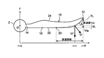
- FIG. 1 is a diagram illustrating a configuration example of a wind turbine generator.
- a wind power generator 1 shown in FIG. 1 includes one or more (three in this example) wind turbine blades 10, a hub 2 to which the wind turbine blades 10 are attached, and a nacelle 4 that supports a rotor including the wind turbine blades 10 and the hub 2. And a tower 6 that rotatably supports the nacelle 4.
- the wind turbine blade 10 is a wind turbine blade having a configuration shown in FIG. 2 described later.
- the rotation of the rotor is input to a generator (not shown), and electric power is generated in the generator.
- the wind turbine blade 10 is attached to the hub 2 by fixing the blade root portion 14 of the wind turbine blade 10 to the hub 2 using an arbitrary fastening member.
- FIG. 2A is a plan view showing a schematic configuration of a typical leading edge straight type wind turbine blade (a wind turbine blade having no receding angle or a very small receding angle).
- 2A includes a blade tip portion 52, a blade root portion 54 configured to be connectable to the hub 2, and an airfoil portion 56 positioned between the blade tip portion 52 and the blade root portion 54. .
- the airfoil 56 has a leading edge. edge 62 and a trailing edge 64.
- the leading edge 62 from the blade root portion 54 to the blade tip portion 52 is a straight line substantially parallel to the blade axis direction BL.
- the blade axis is a straight line passing through the central axis of the cylindrical blade root 54.
- the blade axis direction refers to a direction parallel to the blade axis.
- the distance in the blade axis direction from the rotation center O of the hub 2 to the blade tip 52 is referred to as R, and the distance in the blade axis direction from the rotation center O of the hub 2 to any point on the leading edge 62 is referred to as r.
- the wind turbine blade is configured as follows to suppress erosion at least at the blade tip.
- FIG. 2B is a plan view showing a schematic configuration of the wind turbine blade according to the embodiment of the present invention.
- 2B includes a blade tip portion 12, a blade root portion 14 configured to be connectable to the hub 2, and an airfoil portion 16 positioned between the blade tip portion 12 and the blade root portion 14.
- the airfoil portion 16 has a leading edge 22 and a trailing edge 24.
- the leading edge 22 is retracted with respect to the blade axis direction BL in the retracted region located on the blade tip 12 side of the wind turbine blade 10, and the tangent line TL of the leading edge And the blade axis direction BL (retraction angle) A is set larger than zero.
- the retracted region refers to a region on the blade tip 12 side from the retracting start point 20 of the leading edge 22.
- the influence on the noise is large in the region on the blade tip 12 side (0.9 ⁇ r / R ⁇ 1), and the influence on the noise is maximum in the vicinity of the blade tip 12. become. Therefore, improving the erosion resistance in the range of 0.9 ⁇ r / R ⁇ 1 is beneficial at least from the viewpoint of suppressing noise generation. Further, if the erosion incubation period at the blade tip portion 12 having the greatest damage due to erosion can be improved by about twice as compared with the wind turbine blade 50 of the leading edge linear type, the wind turbine generator 1 near the blade tip of the wind turbine blade 10 is provided. It becomes possible to delay the erosion manifestation until the standard useful life of (for example, 20 to 25 years), and enjoy a sufficient merit.
- the angle A [degree] (hereinafter referred to as the receding angle A) between the tangent TL of the leading edge 22 and the blade axis direction BL is 0.9 ⁇ r.
- Is set to satisfy the relationship.
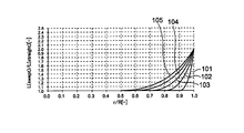
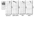
- FIG. 3A is a graph showing the relationship between the radial position r / R and the erosion incubation period
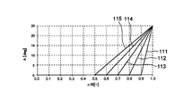
- FIG. 3B is a graph showing the relationship between the radial position r / R and the receding angle of the leading edge.
- the erosion incubation period shown in FIG. 3A is expressed as a ratio of the incubation period Lswept of the wind turbine blade 10 having a receding angle (see FIG. 2B) to the incubation period Lstraight of the leading edge straight type wind turbine blade 50 (see FIG. 2A). ing.
- the receding angle A shown in FIG. 3B is an angle formed by the tangent TL of the leading edge 22 at the radial position r and the blade axis direction BL.
- the above relational expression (2) means that the receding angle A falls within the range above the straight line 111 and the straight line 111 shown in FIG. 3B. Further, the ratio of the erosion latent period Lswept of the leading edge 22 having the receding angle A represented by the straight line 111 to the erosion latent period Lstraight is represented by a curve 101 shown in FIG. 3A. Therefore, when the receding angle A satisfies the above relational expression (2) within the range of the blade axis direction of 0.9 ⁇ r / R ⁇ 1, the ratio of the erosion latency period Lswept to the erosion latency period Lstraight is the curve 101 and the curve It falls within the range above 101.
- the radial position r / R of the receding start point 20 is 0.9, which is beneficial from the viewpoint of suppressing noise generation.
- a sufficient receding angle A is obtained in the blade axial direction range of .9 ⁇ r / R ⁇ 1.
- the erosion incubation period Lswept at the blade tip portion 12 is larger than that of the wind turbine blade 50 of the leading edge linear type as shown by the curve 101 in FIG. Will be doubled.
- the receding angle A of the leading edge 22 so as to satisfy the above relational expression (2), in the region that is likely to cause noise (0.9 ⁇ r / R ⁇ 1), the front of raindrops, dust, etc.
- the collision angle of the edge becomes shallow, the collision speed Vn of the front edge 22 with respect to raindrops, dust and the like is reduced, and erosion resistance is improved.
- the erosion incubation period Lswept at the blade tip portion 12 having the greatest damage due to erosion can be improved by at least about twice as compared with the erosion incubation period Lstraight of the leading edge straight type wind turbine blade 50. Therefore, it becomes possible to delay the erosion manifestation up to the standard useful life (for example, 20 to 25 years) of the wind turbine generator 1 in the vicinity of the blade tip of the wind turbine blade 10, so that sufficient merit can be enjoyed.
- the angle A between the tangent TL of the leading edge 12 and the blade axis direction BL is within the range of the blade axis direction BL of 0.8 ⁇ r / R ⁇ 1. The relationship may be satisfied.
- the above relational expression (3) means that the receding angle A falls within the range above the straight line 112 and the straight line 112 shown in FIG. 3B. Further, the ratio of the erosion latent period Lswept of the leading edge 22 having the receding angle A represented by the straight line 112 to the erosion latent period Lstraight is represented by a curve 102 shown in FIG. 3A. Therefore, when the receding angle A satisfies the above relational expression (3) within the range of 0.8 ⁇ r / R ⁇ 1, the ratio of the erosion latent period Lswept to the erosion latent period Lstraight is the curve 102 and the curve It falls within the range above 102.
- the erosion incubation period Lswept at the blade tip 12 that is most likely to be damaged by erosion and has the greatest influence on noise is improved by at least about twice as compared with the erosion incubation period Lstraight of the leading edge straight type wind turbine blade 50. The erosion can be delayed until the standard service life of the wind turbine generator 1 near the blade tip of the wind turbine blade 10.
- the angle A between the tangent TL of the leading edge 22 and the blade axis direction BL is within the range of the blade axis direction BL of 0.7 ⁇ r / R ⁇ 1. The relationship may be satisfied.
- the above relational expression (4) means that the receding angle A falls within the range above the straight line 113 and the straight line 113 shown in FIG. 3B. Further, the ratio of the erosion latent period Lswept of the leading edge 22 having the receding angle A represented by the straight line 113 to the erosion latent period Lstraight is represented by a curve 103 shown in FIG. 3A. Therefore, when the receding angle A satisfies the relational expression (4) within the range of 0.7 ⁇ r / R ⁇ 1, the ratio of the erosion latent period Lswept to the erosion latent period Lstraight is the curve 103 and the curve It falls within the range above 103.
- the radial position r / R of the receding start point 20 of the windmill blade 10 is 0.8.
- a receding angle A is obtained in a relatively large range of 0.8 ⁇ r / R ⁇ 1 in the blade axis direction.
- the erosion incubation period Lswept at the blade tip 12 is larger than that of the wind turbine blade 50 of the leading edge linear type as shown by the curve 102 in FIG. Will be doubled.
- the erosion suppressing effect can be enjoyed in a wide area on the blade tip side having a relatively large contribution to noise.
- the erosion incubation period Lswept at the blade tip 12 that is most likely to be damaged by erosion and has the greatest effect on noise is improved by at least about twice as compared with the erosion incubation period Lstraight of the leading edge straight type wind turbine blade 50. The erosion can be delayed until the standard service life of the wind turbine generator 1 near the blade tip of the wind turbine blade 10.
- the angle A between the tangent TL of the leading edge 22 and the blade axis direction BL is within the range of the blade axis direction BL of 0.6 ⁇ r / R ⁇ 1. The relationship may be satisfied.
- the above relational expression (5) means that the receding angle A falls within the range on the straight line 114 and the upper side of the straight line 114 shown in FIG. 3B. Further, the ratio of the erosion latent period Lswept of the leading edge 22 having the receding angle A represented by the straight line 114 to the erosion latent period Lstraight is represented by a curve 104 shown in FIG. 3A. Therefore, when the receding angle A satisfies the above relational expression (5) within the range of 0.6 ⁇ r / R ⁇ 1, the ratio of the erosion incubation period Lswept to the erosion incubation period Lstraight is the curve 104 and the curve It falls within the range above 104.
- the receding angle A between the tangent TL of the leading edge 22 and the blade axis direction BL is within the range of the blade axis direction BL of 0.5 ⁇ r / R ⁇ 1. , The relationship may be satisfied.
- the above relational expression (6) means that the receding angle A is included in the range above the straight line 115 and the straight line 115 shown in FIG. 3B. Further, the ratio of the erosion incubation period Lswept of the leading edge 22 having the receding angle A represented by the straight line 115 to the erosion incubation period Lstraight is represented by a curve 105 shown in FIG. 3A. Therefore, when the receding angle A satisfies the relational expression (6) within the range of 0.5 ⁇ r / R ⁇ 1, the ratio of the erosion latent period Lswept to the erosion latent period Lstraight is the curve 105 and the curve It falls within the range above 105.
- the collision angle of the leading edge with respect to raindrops, dust, etc. becomes shallow, so that raindrops, dust,
- the collision speed Vn of the leading edge with respect to etc. is reduced, and the erosion resistance is improved. It is possible to improve the erosion resistance in a region (0.9 ⁇ r / R ⁇ 1) in which the blade axis direction range is likely to cause noise by a simple method of setting the receding angle A, at least suppressing noise generation. Is beneficial from the point of view.
- FIGS. 4 to 6 show the relationship between the configuration of the wind turbine blade according to the embodiment and the erosion incubation period.
- a dotted line shows the value of the leading edge straight type wind turbine blade which is a comparative example.
- the solid line is Example Xa (where X is an integer of 1 to 15), and indicates each value in a wind turbine blade having a receding angle set so that the erosion latent period is uniform from the blade root to the blade tip.
- the alternate long and short dash line is Example Xb (where X is an integer of 1 to 15), and each value in a wind turbine blade having a receding angle set so that the erosion incubation period differs from the blade root to the blade tip is shown. Show.
- the chain double-dashed line is Example Xc (where X is an integer of 1 to 15), and the erosion incubation period differs from the blade root to the blade tip and is set to be smaller than that of Example Xb. Each value in a wind turbine blade having a different receding angle is shown.
Abstract
風車のハブに取り付けられる風車翼であって、 翼先端部と、前記ハブに接続可能に構成された翼根部との間に位置する翼型部を備える風車翼であって、 前記翼型部は、少なくとも前記翼先端部側に設けられた後退領域において翼軸線方向に対して前縁が後退しており、 前記ハブの回転中心から前記翼先端部までの前記翼軸線方向の距離をRとし、前記ハブの回転中心から前記前縁上の任意の点までの前記翼軸線方向の距離をrとしたとき、前記前縁の接線と前記翼軸線方向との間の角度A[度]は、0.9≦r/R≦1の前記翼軸線方向の範囲内において、 の関係を満たすように構成される。
Description
本開示は、風車翼及び風力発電装置に関する。
近年、地球環境の保全の観点から、風力を利用した風力発電装置の普及が進んでいる。風力発電装置は、風の運動エネルギーを翼(正確には翼を含むロータ全体)の回転エネルギーに変換し、さらにこの回転エネルギーを発電機にて電力に変換するようになっている。
風力発電装置は、発電出力の向上の観点から大型化する傾向にあり、これに伴って翼端周速は増加の一途をたどっている。そのため、風車翼の先端において雨滴や砂塵等が衝突し、エロージョンが生じやすくなっている。エロージョンによる風車翼の損傷が顕在化すると、翼表面の平滑性が失われる結果、例えば騒音の増大に代表される望ましくない現象が発生する。
特許文献1には、エロージョンの発生を抑制するための保護コーティングが表面に施された風車翼が開示されている。
また、エロージョン発生の抑制を目的としたものではないが、特許文献2~4には、風車翼として、ロータ回転方向の下流側に後退した後退翼(swept back blade)が開示されている。
しかしながら、風車翼のエロージョン進行速度は、雨滴や砂塵等に対する風車翼の衝突速度に大きく依存するため、僅かな翼長増大に伴う周速増加でエロージョンは大幅に加速されてしまう。そのため、特許文献1に記載のように保護コーティングによって風車翼の耐エロージョン性を高めるという固定概念にとらわれていては、今後のさらなる長翼化の傾向に対応することが難しい。
また、特許文献2~4には、風車翼の耐エロージョン性の向上を目的とした工夫は何ら記載されていない。
また、特許文献2~4には、風車翼の耐エロージョン性の向上を目的とした工夫は何ら記載されていない。
本発明の少なくとも一実施形態の目的は、耐エロージョン性に優れた風車翼及びこれを備えた風力発電装置を提供することである。
本発明の少なくとも一実施形態に係る風車翼は、風車のハブに取り付けられる風車翼であって、
翼先端部と、前記ハブに接続可能に構成された翼根部との間に位置する翼型部を備える風車翼であって、
前記翼型部は、少なくとも前記翼先端部側に設けられた後退領域において翼軸線方向に対して前縁が後退しており、
前記ハブの回転中心から前記翼先端部までの前記翼軸線方向の距離をRとし、前記ハブの回転中心から前記前縁上の任意の点までの前記翼軸線方向の距離をrとしたとき、前記前縁の接線と前記翼軸線方向との間の角度A[度]は、0.9≦r/R≦1の前記翼軸線方向の範囲内において、
 の関係を満たす。
翼先端部と、前記ハブに接続可能に構成された翼根部との間に位置する翼型部を備える風車翼であって、
前記翼型部は、少なくとも前記翼先端部側に設けられた後退領域において翼軸線方向に対して前縁が後退しており、
前記ハブの回転中心から前記翼先端部までの前記翼軸線方向の距離をRとし、前記ハブの回転中心から前記前縁上の任意の点までの前記翼軸線方向の距離をrとしたとき、前記前縁の接線と前記翼軸線方向との間の角度A[度]は、0.9≦r/R≦1の前記翼軸線方向の範囲内において、
上記風車翼によれば、後退領域における前縁は翼軸線方向に対して傾斜しているので、雨滴や砂塵等に対する前縁の衝突角度が浅くなって、雨滴や砂塵等に対する前縁の衝突速度Vnが低減され、耐エロージョン性が向上する。とりわけ、0.9≦r/R≦1の翼軸線方向の範囲内において、前縁の接線と翼軸線方向とのなす角度(後退角)Aが
 の関係を満たすため、この領域において大きなエロージョン抑制効果を享受できる。本発明者の知見によれば0.9≦r/R≦1の翼軸線方向範囲は騒音原因になりやすい領域であるから、前縁の後退角Aの設定という簡素な手法によって上記領域における耐エロージョン性を向上させることができることは、少なくとも騒音発生の抑制の観点から有益である。
幾つかの実施形態では、前記前縁の接線と前記翼軸線方向との間の角度Aは、0.8≦r/R≦1の前記翼軸線方向の範囲内において、
 の関係を満たす。
これにより、騒音への寄与度が比較的大きい0.8≦r/R≦1の翼軸線方向範囲において、エロージョン抑制効果を享受できる。
これにより、騒音への寄与度が比較的大きい0.8≦r/R≦1の翼軸線方向範囲において、エロージョン抑制効果を享受できる。
一実施形態では、前記前縁の接線と前記翼軸線方向との間の角度Aは、0.7≦r/R≦1の前記翼軸線方向の範囲内において、
 の関係を満たす。
本発明者の知見によれば、0.8≦r/R≦0.9の翼軸線方向範囲は発電効率への寄与度が高い。よって、
 の関係を満たすような後退角Aの設定により、0.8≦r/R≦0.9の翼軸線方向範囲における耐エロージョン性を抑制できることは、騒音発生の抑制だけでなく、発電効率維持の観点からも有益である。
本発明者の知見によれば、0.8≦r/R≦0.9の翼軸線方向範囲は発電効率への寄与度が高い。よって、
一実施形態では、前記前縁の接線と前記翼軸線方向との間の角度Aは、0.6≦r/R≦1の前記翼軸線方向の範囲内において、
 の関係を満たす。
これにより、エロージョンに起因した発電効率低下をより効果的に抑制できる。
これにより、エロージョンに起因した発電効率低下をより効果的に抑制できる。
一実施形態では、前記前縁の接線と前記翼軸線方向との間の角度Aは、0.5≦r/R≦1の前記翼軸線方向の範囲内において、
 の関係を満たす。
これにより、エロージョンに起因した発電効率低下をより一層効果的に抑制できる。
これにより、エロージョンに起因した発電効率低下をより一層効果的に抑制できる。
本発明の少なくとも一実施形態に係る風力発電装置は、
少なくとも一枚の風車翼と、
各々の前記風車翼が取り付けられるハブと、
前記ハブ及び前記少なくとも一本の風車翼を含むロータの回転エネルギーを電力に変換するための発電機とを備える風力発電装置であって、
各々の前記風車翼は、翼先端部と、前記ハブに接続可能に構成された翼根部との間に位置する翼型部を含み、
前記翼型部は、少なくとも前記翼先端部側に設けられた後退領域において翼軸線方向に対して前縁が後退しており、
前記ハブの回転中心から前記翼先端部までの前記翼軸線方向の距離をRとし、前記ハブの回転中心から前記前縁上の任意の点までの前記翼軸線方向の距離をrとしたとき、前記前縁の接線と前記翼軸線方向との間の角度A[度]は、0.9≦r/R≦1の前記翼軸線方向の範囲内において、
 の関係を満たす。
少なくとも一枚の風車翼と、
各々の前記風車翼が取り付けられるハブと、
前記ハブ及び前記少なくとも一本の風車翼を含むロータの回転エネルギーを電力に変換するための発電機とを備える風力発電装置であって、
各々の前記風車翼は、翼先端部と、前記ハブに接続可能に構成された翼根部との間に位置する翼型部を含み、
前記翼型部は、少なくとも前記翼先端部側に設けられた後退領域において翼軸線方向に対して前縁が後退しており、
前記ハブの回転中心から前記翼先端部までの前記翼軸線方向の距離をRとし、前記ハブの回転中心から前記前縁上の任意の点までの前記翼軸線方向の距離をrとしたとき、前記前縁の接線と前記翼軸線方向との間の角度A[度]は、0.9≦r/R≦1の前記翼軸線方向の範囲内において、
上記風力発電装置によれば、後退領域における前縁は翼軸線方向に対して傾斜しているので、雨滴や砂塵等に対する前縁の衝突角度が浅くなって、雨滴や砂塵等に対する前縁の衝突速度Vnが低減され、耐エロージョン性が向上する。とりわけ、0.9≦r/R≦1の翼軸線方向の範囲内において、前縁の接線と翼軸線方向とのなす角度(後退角)Aが
 の関係を満たすため、この領域において大きなエロージョン抑制効果を享受できる。このように、後退角Aの設定という簡素な手法によって翼軸線方向範囲は騒音原因になりやすい領域(0.9≦r/R≦1の)における耐エロージョン性を向上させることができることは、少なくとも騒音発生の抑制の観点から有益である。
幾つかの実施形態では、前記前縁の接線と前記翼軸線方向との間の角度Aは、0.8≦r/R≦1の前記翼軸線方向の範囲内において、
 の関係を満たす。
本発明の少なくとも一実施形態によれば、後退領域における前縁は翼軸線方向に対して傾斜しているので、雨滴や砂塵等に対する前縁の衝突角度が浅くなって、雨滴や砂塵等に対する前縁の衝突速度Vnが低減され、耐エロージョン性が向上する。とりわけ、0.9≦r/R≦1の翼軸線方向の範囲内において、前縁の接線と翼軸線方向とのなす角度(後退角)Aが
 の関係を満たすため、この領域において大きなエロージョン抑制効果を享受できる。このように、後退角Aの設定という簡素な手法によって翼軸線方向範囲は騒音原因になりやすい領域(0.9≦r/R≦1の)における耐エロージョン性を向上させることができることは、少なくとも騒音発生の抑制の観点から有益である。
以下、添付図面に従って本発明の実施形態について説明する。ただし、実施形態として以下に記載され、あるいは、実施形態として図面で示された構成部品の寸法、材質、形状、その相対的配置等は、本発明の範囲をこれに限定する趣旨ではなく、単なる説明例にすぎない。
図1は、風力発電装置の構成例を示す図である。
図1に示す風力発電装置1は、1本以上(この例では3本)の風車翼10と、風車翼10が取り付けられるハブ2と、風車翼10及びハブ2を含むロータを支持するナセル4と、ナセル4を旋回自在に支持するタワー6とを備える。ここで、幾つかの実施形態では、風車翼10は、後述する図2に示す構成を備える風車翼である。なお、ロータの回転は不図示の発電機に入力されて、該発電機において電力が生成されるようになっている。風車翼10のハブ2への取付けは、風車翼10の翼根部14をハブ2に任意の締結部材を用いて固定することで行われる。
図1に示す風力発電装置1は、1本以上(この例では3本)の風車翼10と、風車翼10が取り付けられるハブ2と、風車翼10及びハブ2を含むロータを支持するナセル4と、ナセル4を旋回自在に支持するタワー6とを備える。ここで、幾つかの実施形態では、風車翼10は、後述する図2に示す構成を備える風車翼である。なお、ロータの回転は不図示の発電機に入力されて、該発電機において電力が生成されるようになっている。風車翼10のハブ2への取付けは、風車翼10の翼根部14をハブ2に任意の締結部材を用いて固定することで行われる。
図2Aは典型的な前縁直線型の風車翼(後退角を有しない又は後退角が非常に小さい風車翼)の概略構成を示す平面図である。
図2Aに示す風車翼50は、翼先端部52と、ハブ2に接続可能に構成された翼根部54と、翼先端部52と翼根部54との間に位置する翼型部56とを備える。翼型部56は、前縁(leading
edge)62と後縁(trailing edge)64とを有する。この風車翼50では、翼根部54から翼先端部52まで前縁62が翼軸線方向BLにほぼ平行な直線となっている。
なお、本明細書において、翼軸線とは、円筒状の翼根部54の中心軸を通る直線である。よって、翼軸線方向は、翼軸線に平行な方向をいう。また、ハブ2の回転中心Oから翼先端部52までの翼軸線方向の距離をR、ハブ2の回転中心Oから前縁62上の任意の点までの翼軸線方向の距離をrと称する。
ところで、風車翼のエロージョンによって損傷が顕在化するまでの時間(エロージョン潜伏期間)Lは、雨滴や砂塵等に対する風車翼の衝突速度Vnとの間に、L∝Vn-6.7の関係が成立することが経験的に分かっている。ここで、雨滴や砂塵等の移動速度は風車翼の周速Vrに比べてはるかに小さいため、衝突速度Vnは風車翼の周速Vrで近似できる。風車翼の周速Vrは半径位置rに比例する。そのため、前縁62が翼軸線方向BLに平行な直線である風車翼50の場合、基準半径位置r*におけるエロージョン潜伏期間をL*とすれば、基準半径位置r*よりも翼先端52側の任意の半径位置r(>r*)におけるエロージョン潜伏期間Lは下記式(1)によって表される。
L=(r*/r)6.7×L* (1)
したがって、風車翼50においては、翼先端52に近づけば近づくほど、エロージョンの進行速度は大きくなり、エロージョンによる損傷が表れやすい。特に、翼先端52では、周速Vtipが翼全体の中で最も大きくなるので、最もエロージョンによって損傷しやすくなる。
L=(r*/r)6.7×L* (1)
したがって、風車翼50においては、翼先端52に近づけば近づくほど、エロージョンの進行速度は大きくなり、エロージョンによる損傷が表れやすい。特に、翼先端52では、周速Vtipが翼全体の中で最も大きくなるので、最もエロージョンによって損傷しやすくなる。
そこで、幾つかの実施形態では、少なくとも翼先端部におけるエロージョンを抑制するために風車翼を以下のように構成する。
図2Bは本発明の実施形態に係る風車翼の概略構成を示す平面図である。
図2Bに示す風車翼10は、翼先端部12と、ハブ2に接続可能に構成された翼根部14と、翼先端部12と翼根部14との間に位置する翼型部16とを備える。翼型部16は、前縁22と後縁24とを有する。
図2Bに示す風車翼10は、翼先端部12と、ハブ2に接続可能に構成された翼根部14と、翼先端部12と翼根部14との間に位置する翼型部16とを備える。翼型部16は、前縁22と後縁24とを有する。
風車翼10の場合、半径位置rにおける前縁22のエロージョン潜伏期間を決定付ける衝突速度Vnは、半径位置rにおける周速Vrそのものではなく、大きさがVrの周速ベクトルのうち前縁22の法線方向に沿った成分Vr’である。すなわち、半径位置rにおける前縁22の接線TLと翼軸線方向BLがなす角度(後退角)をAとすれば、衝突速度Vn=Vr×cosAで表される。
そのため、翼先端近傍におけるエロージョンの進行を抑制するために、風車翼10の翼先端12側に位置する後退領域において、翼軸線方向BLに対して前縁22を後退させて、前縁の接線TLと翼軸線方向BLとの間の角度(後退角)Aをゼロよりも大きく設定する。なお、後退領域とは、前縁22の後退開始点20より翼先端12側の領域をいう。
そのため、翼先端近傍におけるエロージョンの進行を抑制するために、風車翼10の翼先端12側に位置する後退領域において、翼軸線方向BLに対して前縁22を後退させて、前縁の接線TLと翼軸線方向BLとの間の角度(後退角)Aをゼロよりも大きく設定する。なお、後退領域とは、前縁22の後退開始点20より翼先端12側の領域をいう。
ここで、本発明者の知見によれば、翼先端部12側の領域(0.9≦r/R≦1)において騒音への影響が大きく、翼先端部12近傍において騒音への影響が最大になる。したがって、0.9≦r/R≦1の範囲における耐エロージョン性を向上させることは、少なくとも騒音発生の抑制の観点から有益である。
また、エロージョンによる損傷が最も大きい翼先端部12におけるエロージョン潜伏期間を、前縁直線型の風車翼50に比べて2倍程度向上させることができれば、風車翼10の翼先端近傍において風力発電装置1の標準耐用年数(例えば20年~25年)までエロージョンの顕在化を遅らせることが可能になり、十分なメリットを享受できる。
また、エロージョンによる損傷が最も大きい翼先端部12におけるエロージョン潜伏期間を、前縁直線型の風車翼50に比べて2倍程度向上させることができれば、風車翼10の翼先端近傍において風力発電装置1の標準耐用年数(例えば20年~25年)までエロージョンの顕在化を遅らせることが可能になり、十分なメリットを享受できる。
そこで、幾つかの実施形態では、風車翼10において、前縁22の接線TLと翼軸線方向BLとの間の角度A[度](以下、後退角Aと称する)は、0.9≦r/R≦1の翼軸線方向の範囲内において、
 の関係を満たすように設定される。
上記後退角Aの範囲について、図3A及び図3Bを参照して具体的に説明する。図3Aは半径位置r/Rとエロージョン潜伏期間との関係を示すグラフで、図3Bは半径位置r/Rと前縁の後退角との関係を示すグラフである。なお、図3Aに示すエロージョン潜伏期間は、前縁直線型の風車翼50(図2A参照)の潜伏期間Lstraightに対する、後退角を有する風車翼10(図2B参照)の潜伏期間Lsweptの比として表している。図3Bに示す後退角Aは、半径位置rにおける前縁22の接線TLと翼軸線方向BLがなす角度である。
上記関係式(2)は、後退角Aが、図3Bに示す直線111及び直線111よりも上側の範囲内に収まることを意味する。また、直線111で表される後退角Aを有する前縁22のエロージョン潜伏期間Lsweptのエロージョン潜伏期間Lstraightに対する比は、図3Aに示す曲線101で表される。よって、0.9≦r/R≦1の翼軸線方向の範囲内において後退角Aが上記関係式(2)を満たす場合、エロージョン潜伏期間Lstraightに対するエロージョン潜伏期間Lsweptの比は、曲線101及び曲線101よりも上側の範囲内に収まる。
図3Bに示す直線111に従った後退角Aの分布を有する風車翼10の場合、後退開始点20の半径位置r/Rが0.9であるため、騒音発生の抑制の観点から有益な0.9≦r/R≦1の翼軸線方向範囲において十分な後退角Aが得られる。また、直線111に従った後退角Aの分布を有する風車翼10の場合、翼先端部12におけるエロージョン潜伏期間Lsweptは、図3Aの曲線101に示すように前縁直線型の風車翼50に比べて2倍となる。
こうして、上記関係式(2)を満たすように前縁22の後退角Aを設定することで、騒音原因になりやすい領域(0.9≦r/R≦1)において、雨滴や砂塵等に対する前縁の衝突角度が浅くなって、雨滴や砂塵等に対する前縁22の衝突速度Vnが低減され、耐エロージョン性が向上する。
また、エロージョンによる損傷が最も大きい翼先端部12におけるエロージョン潜伏期間Lsweptを前縁直線型の風車翼50のエロージョン潜伏期間Lstraightに比べて少なくとも2倍程度向上させることができる。したがって、風車翼10の翼先端近傍において風力発電装置1の標準耐用年数(例えば20年~25年)までエロージョンの顕在化を遅らせることが可能になり、十分なメリットを享受できる。
また、エロージョンによる損傷が最も大きい翼先端部12におけるエロージョン潜伏期間Lsweptを前縁直線型の風車翼50のエロージョン潜伏期間Lstraightに比べて少なくとも2倍程度向上させることができる。したがって、風車翼10の翼先端近傍において風力発電装置1の標準耐用年数(例えば20年~25年)までエロージョンの顕在化を遅らせることが可能になり、十分なメリットを享受できる。
一実施形態では、風車翼10において、前縁12の接線TLと翼軸線方向BLとの間の角度Aが、0.8≦r/R≦1の翼軸線方向BLの範囲内において、
 の関係を満たすようにしてもよい。
上記関係式(3)は、後退角Aが、図3Bに示す直線112上及び直線112よりも上側の範囲内に収まることを意味している。また、直線112で表される後退角Aを有する前縁22のエロージョン潜伏期間Lsweptのエロージョン潜伏期間Lstraightに対する比は、図3Aに示す曲線102で表される。よって、0.8≦r/R≦1の翼軸線方向の範囲内において後退角Aが上記関係式(3)を満たす場合、エロージョン潜伏期間Lstraightに対するエロージョン潜伏期間Lsweptの比は、曲線102及び曲線102よりも上側の範囲内に収まる。
図3Bに示す直線112に従った後退角Aの分布を有する風車翼10の場合、後退開始点20の半径位置r/Rが0.8であるため、騒音への寄与度が比較的大きい0.8≦r/R≦1の翼軸線方向範囲において十分な後退角Aが得られる。また、直線112に従った後退角Aの分布を有する風車翼10の場合、翼先端部12におけるエロージョン潜伏期間Lsweptは、図3Aの曲線102に示すように前縁直線型の風車翼50に比べて2倍となる。
こうして、上記関係式(3)を満たすように前縁22の後退角Aを設定することで、騒音への寄与度が比較的大きい0.8≦r/R≦1の翼軸線方向範囲において、エロージョン抑制効果を享受できる。特に、エロージョンによる損傷が最も起こりやすく、騒音への影響も最も大きい翼先端部12におけるエロージョン潜伏期間Lsweptを前縁直線型の風車翼50のエロージョン潜伏期間Lstraightに比べて少なくとも2倍程度向上させることができ、風車翼10の翼先端近傍において風力発電装置1の標準耐用年数までエロージョンの顕在化を遅らせることができる。
こうして、上記関係式(3)を満たすように前縁22の後退角Aを設定することで、騒音への寄与度が比較的大きい0.8≦r/R≦1の翼軸線方向範囲において、エロージョン抑制効果を享受できる。特に、エロージョンによる損傷が最も起こりやすく、騒音への影響も最も大きい翼先端部12におけるエロージョン潜伏期間Lsweptを前縁直線型の風車翼50のエロージョン潜伏期間Lstraightに比べて少なくとも2倍程度向上させることができ、風車翼10の翼先端近傍において風力発電装置1の標準耐用年数までエロージョンの顕在化を遅らせることができる。
また、一実施形態では、風車翼10において、前縁22の接線TLと翼軸線方向BLとの間の角度Aが、0.7≦r/R≦1の翼軸線方向BLの範囲内において、
 の関係を満たすようにしてもよい。
上記関係式(4)は、後退角Aが、図3Bに示す直線113上及び直線113よりも上側の範囲内に収まることを意味している。また、直線113で表される後退角Aを有する前縁22のエロージョン潜伏期間Lsweptのエロージョン潜伏期間Lstraightに対する比は、図3Aに示す曲線103で表される。よって、0.7≦r/R≦1の翼軸線方向の範囲内において後退角Aが上記関係式(4)を満たす場合、エロージョン潜伏期間Lstraightに対するエロージョン潜伏期間Lsweptの比は、曲線103及び曲線103よりも上側の範囲内に収まる。
図3Bに示す直線113に従った後退角Aの分布を有する風車翼10の場合、風車翼10の後退開始点20の半径位置r/Rが0.8であるため、騒音への寄与度が比較的大きい0.8≦r/R≦1の翼軸線方向範囲において後退角Aが得られる。また、直線112に従った後退角Aの分布を有する風車翼10の場合、翼先端部12におけるエロージョン潜伏期間Lsweptは、図3Aの曲線102に示すように前縁直線型の風車翼50に比べて2倍となる。
こうして、上記関係式(4)を満たすように前縁22の後退角Aを設定することで、騒音への寄与度が比較的大きい翼先端側の広範な領域において、エロージョン抑制効果を享受できる。特に、エロージョンによる損傷が最も起こりやすく、騒音への影響も最も大きい翼先端部12におけるエロージョン潜伏期間Lsweptを前縁直線型の風車翼50のエロージョン潜伏期間Lstraightに比べて少なくとも2倍程度向上させることができ、風車翼10の翼先端近傍において風力発電装置1の標準耐用年数までエロージョンの顕在化を遅らせることができる。
こうして、上記関係式(4)を満たすように前縁22の後退角Aを設定することで、騒音への寄与度が比較的大きい翼先端側の広範な領域において、エロージョン抑制効果を享受できる。特に、エロージョンによる損傷が最も起こりやすく、騒音への影響も最も大きい翼先端部12におけるエロージョン潜伏期間Lsweptを前縁直線型の風車翼50のエロージョン潜伏期間Lstraightに比べて少なくとも2倍程度向上させることができ、風車翼10の翼先端近傍において風力発電装置1の標準耐用年数までエロージョンの顕在化を遅らせることができる。
さらに、上記関係式(4)を満たすように前縁22の後退角Aを設定することで、発電効率への寄与度が高い0.8≦r/R≦0.9の翼軸線方向範囲におけるエロージョンの進行を遅らせることができる。このことは、図3Aにおける曲線103から明らかである。
したがって、上記関係式(4)を満たすように前縁22の後退角Aを設定すれば、騒音発生の抑制だけでなく、発電効率維持の観点からも有益である。
したがって、上記関係式(4)を満たすように前縁22の後退角Aを設定すれば、騒音発生の抑制だけでなく、発電効率維持の観点からも有益である。
また、一実施形態では、風車翼10において、前縁22の接線TLと翼軸線方向BLとの間の角度Aが、0.6≦r/R≦1の翼軸線方向BLの範囲内において、
 の関係を満たすようにしてもよい。
上記関係式(5)は、後退角Aが、図3Bに示す直線114上及び直線114よりも上側の範囲内に収まることを意味する。また、直線114で表される後退角Aを有する前縁22のエロージョン潜伏期間Lsweptのエロージョン潜伏期間Lstraightに対する比は、図3Aに示す曲線104で表される。よって、0.6≦r/R≦1の翼軸線方向の範囲内において後退角Aが上記関係式(5)を満たす場合、エロージョン潜伏期間Lstraightに対するエロージョン潜伏期間Lsweptの比は、曲線104及び曲線104よりも上側の範囲内に収まる。
図3Bに示す直線114に従った後退角Aの分布を有する風車翼10の場合、後退開始点20の半径位置r/Rが0.6であるため、発電効率維持への寄与度が比較的大きい0.6≦r/R≦1の翼軸線方向範囲において十分な後退角Aが得られる。これにより、騒音発生の抑制効果に加えて、エロージョンに起因した発電効率低下をより効果的に抑制できる。
さらに、一実施形態では、風車翼10において、前縁22の接線TLと翼軸線方向BLとの間の後退角Aが、0.5≦r/R≦1の翼軸線方向BLの範囲内において、
 の関係を満たすようにしてもよい。
上記関係式(6)は、後退角Aが、図3Bに示す直線115上及び直線115よりも上側の範囲内に含まれることを意味する。また、直線115で表される後退角Aを有する前縁22のエロージョン潜伏期間Lsweptのエロージョン潜伏期間Lstraightに対する比は、図3Aに示す曲線105で表される。よって、0.5≦r/R≦1の翼軸線方向の範囲内において後退角Aが上記関係式(6)を満たす場合、エロージョン潜伏期間Lstraightに対するエロージョン潜伏期間Lsweptの比は、曲線105及び曲線105よりも上側の範囲内に収まる。
図3Bに示す直線115に従った後退角Aの分布を有する風車翼10の場合、後退開始点20の半径位置r/Rが0.5であるため、発電効率維持への寄与度が比較的大きい0.5≦r/R≦1の翼軸線方向範囲において十分な後退角Aが得られる。これにより、騒音発生の抑制効果に加えて、エロージョンに起因した発電効率低下をより一層効果的に抑制できる。
以上説明したように、上述の実施形態によれば、後退領域における前縁は翼軸線方向に対して傾斜しているので、雨滴や砂塵等に対する前縁の衝突角度が浅くなって、雨滴や砂塵等に対する前縁の衝突速度Vnが低減され、耐エロージョン性が向上する。後退角Aの設定という簡素な手法によって翼軸線方向範囲は騒音原因になりやすい領域(0.9≦r/R≦1の)における耐エロージョン性を向上させることができることは、少なくとも騒音発生の抑制の観点から有益である。
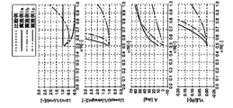
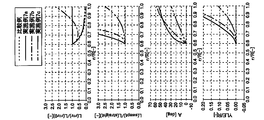
図4~図6に、一実施形態に係る風車翼の構成とエロージョン潜伏期間との関係について示す。
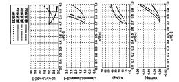
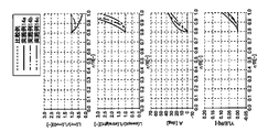
図4A~図4Eは、k=2の場合の各半径位置におけるエロージョン潜伏期間、前縁の後退角及び後退量をそれぞれ示すグラフである。図5A~図5Eは、k=2.5の場合の各半径位置におけるエロージョン潜伏期間、前縁の後退角及び後退量をそれぞれ示すグラフである。図6A~図6Eは、k=3の場合の各半径位置におけるエロージョン潜伏期間、前縁の後退角及び後退量をそれぞれ示すグラフである。
なお、kは、前縁直線型の風車翼(図2A参照)に対する、後退翼を有する風車翼(図2B参照)のエロージョン潜伏期間の比の翼先端における値である。すなわち、k=2の場合、前縁直線型の風車翼のエロージョン潜伏期間Lstraightに比べて後退翼を有する風車翼のエロージョン潜伏期間Lsweptが翼先端において2倍である。同様に、k=2.5の場合、前縁直線型の風車翼のエロージョン潜伏期間Lstraightに比べて後退翼を有する風車翼のエロージョン潜伏期間Lsweptが翼先端において2.5倍である。また、k=3.0の場合、前縁直線型の風車翼のエロージョン潜伏期間Lstraightに比べて後退翼を有する風車翼のエロージョン潜伏期間Lsweptが翼先端において3倍である。
各図には、上から順に、後退開始点r0におけるエロージョン潜伏期間L(r=r0)に対する半径位置rにおけるエロージョン潜伏期間L(r=r)の比(L(r=r)/L(r=r0)を表すグラフと、前縁直線型の風車翼に対する、後退角を有する風車翼のエロージョン潜伏期間の比(L(swept)/L(straight)を表すグラフと、後退角Aを表すグラフと、後退量YLEを回転半径Rで除して無次元化した値を表すグラフとを示している。
各図において、点線は比較例である前縁直線型の風車翼の値を示す。実線は実施例Xa(ただし、Xは1以上15以下の整数)であり、エロージョン潜伏期間が翼根から翼先端まで均一となるように設定された後退角を有する風車翼における各値を示す。一点鎖線は実施例Xb(ただし、Xは1以上15以下の整数)であり、エロージョン潜伏期間が翼根から翼先端までの間で異なるように設定された後退角を有する風車翼における各値を示す。二点鎖線は実施例Xc(ただし、Xは1以上15以下の整数)であり、エロージョン潜伏期間が、翼根から翼先端までの間で異なり、且つ、実施例Xbより小さくなるように設定された後退角を有する風車翼における各値を示す。
各図において、点線は比較例である前縁直線型の風車翼の値を示す。実線は実施例Xa(ただし、Xは1以上15以下の整数)であり、エロージョン潜伏期間が翼根から翼先端まで均一となるように設定された後退角を有する風車翼における各値を示す。一点鎖線は実施例Xb(ただし、Xは1以上15以下の整数)であり、エロージョン潜伏期間が翼根から翼先端までの間で異なるように設定された後退角を有する風車翼における各値を示す。二点鎖線は実施例Xc(ただし、Xは1以上15以下の整数)であり、エロージョン潜伏期間が、翼根から翼先端までの間で異なり、且つ、実施例Xbより小さくなるように設定された後退角を有する風車翼における各値を示す。
図4A~図4Eに示すように、k=2においては、r/Rの位置に関わらず、実施例Xa~Xc(ただし、Xは1以上5以下の整数)ではエロージョン潜伏期間が比較例よりも大きくなる。また、比較例では翼根部と翼先端部との間でエロージョン潜伏期の差が大きかったものの、実施例1~3では翼根部と翼先端部との間でエロージョン潜伏期の差が小さくなる。
図5A~図5E及び図6A~図6Eにおいても、図4A~図4Eと同様のことが言える。したがって、本発明の実施形態によれば、耐エロージョン性の高い風車翼を提供できることは明瞭である。
図5A~図5E及び図6A~図6Eにおいても、図4A~図4Eと同様のことが言える。したがって、本発明の実施形態によれば、耐エロージョン性の高い風車翼を提供できることは明瞭である。
以上、本発明の実施形態について詳細に説明したが、本発明はこれに限定されず、本発明の要旨を逸脱しない範囲において、各種の改良や変形を行ってもよいのはいうまでもない。
1 風力発電装置
2 ハブ
4 ロータ
6 タワー
10,50 風車翼
12,52 翼先端部
14,54 翼根部
16,56 翼型部
22,62 前縁
24,64 後縁
2 ハブ
4 ロータ
6 タワー
10,50 風車翼
12,52 翼先端部
14,54 翼根部
16,56 翼型部
22,62 前縁
24,64 後縁
Claims (10)
- 風車のハブに取り付けられる風車翼であって、
翼先端部と、前記ハブに接続可能に構成された翼根部との間に位置する翼型部を備える風車翼であって、
前記翼型部は、少なくとも前記翼先端部側に設けられた後退領域において翼軸線方向に対して前縁が後退しており、
前記ハブの回転中心から前記翼先端部までの前記翼軸線方向の距離をRとし、前記ハブの回転中心から前記前縁上の任意の点までの前記翼軸線方向の距離をrとしたとき、前記前縁の接線と前記翼軸線方向との間の角度A[度]は、0.9≦r/R≦1の前記翼軸線方向の範囲内において、
の関係を満たすことを特徴とする風車翼。
- 前記前縁の接線と前記翼軸線方向との間の角度Aは、0.8≦r/R≦1の前記翼軸線方向の範囲内において、
の関係を満たすことを特徴とする請求項1に記載の風車翼。
- 前記前縁の接線と前記翼軸線方向との間の角度Aは、0.7≦r/R≦1の前記翼軸線方向の範囲内において、
の関係を満たすことを特徴とする請求項2に記載の風車翼。
- 前記前縁の接線と前記翼軸線方向との間の角度Aは、0.6≦r/R≦1の前記翼軸線方向の範囲内において、
の関係を満たすことを特徴とする請求項3に記載の風車翼。
- 前記前縁の接線と前記翼軸線方向との間の角度Aは、0.5≦r/R≦1の前記翼軸線方向の範囲内において、
の関係を満たすことを特徴とする請求項4に記載の風車翼。
- 少なくとも一枚の風車翼と、
各々の前記風車翼が取り付けられるハブと、
前記ハブ及び前記少なくとも一本の風車翼を含むロータの回転エネルギーを電力に変換するための発電機とを備える風力発電装置であって、
各々の前記風車翼は、翼先端部と、前記ハブに接続可能に構成された翼根部との間に位置する翼型部を含み、
前記翼型部は、少なくとも前記翼先端部側に設けられた後退領域において翼軸線方向に対して前縁が後退しており、
前記ハブの回転中心から前記翼先端部までの前記翼軸線方向の距離をRとし、前記ハブの回転中心から前記前縁上の任意の点までの前記翼軸線方向の距離をrとしたとき、前記前縁の接線と前記翼軸線方向との間の角度A[度]は、0.9≦r/R≦1の前記翼軸線方向の範囲内において、
の関係を満たすことを特徴とする風力発電装置。
- 前記前縁の接線と前記翼軸線方向との間の角度Aは、0.8≦r/R≦1の前記翼軸線方向の範囲内において、
の関係を満たすことを特徴とする請求項6に記載の風力発電装置。
- 前記前縁の接線と前記翼軸線方向との間の角度Aは、0.7≦r/R≦1の前記翼軸線方向の範囲内において、
の関係を満たすことを特徴とする請求項7に記載の風力発電装置。
- 前記前縁の接線と前記翼軸線方向との間の角度Aは、0.6≦r/R≦1の前記翼軸線方向の範囲内において、
の関係を満たすことを特徴とする請求項8に記載の風力発電装置。
- 前記前縁の接線と前記翼軸線方向との間の角度Aは、0.5≦r/R≦1の前記翼軸線方向の範囲内において、
の関係を満たすことを特徴とする請求項9に記載の風力発電装置。

Priority Applications (3)
| Application Number | Priority Date | Filing Date | Title |
|---|---|---|---|
| JP2015502596A JP6009058B2 (ja) | 2013-02-26 | 2013-02-26 | 風車翼及びこれを備えた風力発電装置 |
| EP13876437.8A EP2896826B1 (en) | 2013-02-26 | 2013-02-26 | Windmill vane and wind power generation device provided with same |
| PCT/JP2013/054918 WO2014132328A1 (ja) | 2013-02-26 | 2013-02-26 | 風車翼及びこれを備えた風力発電装置 |
Applications Claiming Priority (1)
| Application Number | Priority Date | Filing Date | Title |
|---|---|---|---|
| PCT/JP2013/054918 WO2014132328A1 (ja) | 2013-02-26 | 2013-02-26 | 風車翼及びこれを備えた風力発電装置 |
Publications (1)
| Publication Number | Publication Date |
|---|---|
| WO2014132328A1 true WO2014132328A1 (ja) | 2014-09-04 |
Family
ID=51427633
Family Applications (1)
| Application Number | Title | Priority Date | Filing Date |
|---|---|---|---|
| PCT/JP2013/054918 WO2014132328A1 (ja) | 2013-02-26 | 2013-02-26 | 風車翼及びこれを備えた風力発電装置 |
Country Status (3)
| Country | Link |
|---|---|
| EP (1) | EP2896826B1 (ja) |
| JP (1) | JP6009058B2 (ja) |
| WO (1) | WO2014132328A1 (ja) |
Cited By (2)
| Publication number | Priority date | Publication date | Assignee | Title |
|---|---|---|---|---|
| JP6245486B1 (ja) * | 2017-03-14 | 2017-12-13 | 中澤 弘幸 | 回転装置、推進装置及び発電装置 |
| CN113719408A (zh) * | 2021-09-23 | 2021-11-30 | 中国华能集团清洁能源技术研究院有限公司 | 一种风电机组后掠叶片和风电机组 |
Families Citing this family (1)
| Publication number | Priority date | Publication date | Assignee | Title |
|---|---|---|---|---|
| CN106593761B (zh) * | 2016-12-19 | 2020-06-23 | 北京金风科创风电设备有限公司 | 叶片及包括叶片的风力发电机、阳模及制造阳模的方法 |
Citations (8)
| Publication number | Priority date | Publication date | Assignee | Title |
|---|---|---|---|---|
| JP2000310179A (ja) * | 1999-04-27 | 2000-11-07 | Fuji Heavy Ind Ltd | 水平軸風車用ロータ |
| DE10332875A1 (de) * | 2003-07-19 | 2005-02-17 | Natenco-Natural Energy Corp. Gmbh | Rotorflügelblatt |
| JP2006152864A (ja) | 2004-11-26 | 2006-06-15 | Ishikawajima Harima Heavy Ind Co Ltd | 風力発電機用ブレード及びそれを備えた風力発電装置 |
| JP2006521483A (ja) * | 2003-01-02 | 2006-09-21 | アロイス・ヴォベン | 風力発電設備用のローターブレード |
| US7344360B2 (en) | 2004-09-29 | 2008-03-18 | General Electric Company | Wind turbine rotor blade with in-plane sweep and devices using same, and methods for making same |
| US20090324416A1 (en) | 2008-06-30 | 2009-12-31 | Ge Wind Energy Gmbh | Wind turbine blades with multiple curvatures |
| US20110142678A1 (en) | 2010-11-23 | 2011-06-16 | General Electric Company | Erosion protection coating for rotor blade of wind turbine |
| JP2012251448A (ja) * | 2011-06-01 | 2012-12-20 | Toru Fukushima | 直径10m以上のプロペラ型風力発電機のブレード減音の形状形態 |
Family Cites Families (5)
| Publication number | Priority date | Publication date | Assignee | Title |
|---|---|---|---|---|
| US7690895B2 (en) * | 2005-07-29 | 2010-04-06 | General Electric Company | Multi-piece passive load reducing blades and wind turbines using same |
| DE102006019204A1 (de) * | 2006-04-21 | 2007-10-25 | Günther Hacker | Windkraftanlage |
| CN101641519B (zh) * | 2007-02-28 | 2012-09-05 | 歌美飒创新技术公司 | 风力涡轮机叶片 |
| NL2004555C2 (en) * | 2010-04-15 | 2011-10-18 | Green X B V | Wing for generating lift from an incident flow. |
| DE102012103704A1 (de) * | 2011-04-30 | 2012-10-31 | General Electric Co. | Winglet für einen Rotorflügel einer Windkraftanlage |
-
2013
- 2013-02-26 WO PCT/JP2013/054918 patent/WO2014132328A1/ja active Application Filing
- 2013-02-26 EP EP13876437.8A patent/EP2896826B1/en active Active
- 2013-02-26 JP JP2015502596A patent/JP6009058B2/ja active Active
Patent Citations (8)
| Publication number | Priority date | Publication date | Assignee | Title |
|---|---|---|---|---|
| JP2000310179A (ja) * | 1999-04-27 | 2000-11-07 | Fuji Heavy Ind Ltd | 水平軸風車用ロータ |
| JP2006521483A (ja) * | 2003-01-02 | 2006-09-21 | アロイス・ヴォベン | 風力発電設備用のローターブレード |
| DE10332875A1 (de) * | 2003-07-19 | 2005-02-17 | Natenco-Natural Energy Corp. Gmbh | Rotorflügelblatt |
| US7344360B2 (en) | 2004-09-29 | 2008-03-18 | General Electric Company | Wind turbine rotor blade with in-plane sweep and devices using same, and methods for making same |
| JP2006152864A (ja) | 2004-11-26 | 2006-06-15 | Ishikawajima Harima Heavy Ind Co Ltd | 風力発電機用ブレード及びそれを備えた風力発電装置 |
| US20090324416A1 (en) | 2008-06-30 | 2009-12-31 | Ge Wind Energy Gmbh | Wind turbine blades with multiple curvatures |
| US20110142678A1 (en) | 2010-11-23 | 2011-06-16 | General Electric Company | Erosion protection coating for rotor blade of wind turbine |
| JP2012251448A (ja) * | 2011-06-01 | 2012-12-20 | Toru Fukushima | 直径10m以上のプロペラ型風力発電機のブレード減音の形状形態 |
Cited By (3)
| Publication number | Priority date | Publication date | Assignee | Title |
|---|---|---|---|---|
| JP6245486B1 (ja) * | 2017-03-14 | 2017-12-13 | 中澤 弘幸 | 回転装置、推進装置及び発電装置 |
| WO2018168689A1 (ja) * | 2017-03-14 | 2018-09-20 | 中澤 弘幸 | 回転装置、推進装置及び発電装置 |
| CN113719408A (zh) * | 2021-09-23 | 2021-11-30 | 中国华能集团清洁能源技术研究院有限公司 | 一种风电机组后掠叶片和风电机组 |
Also Published As
| Publication number | Publication date |
|---|---|
| EP2896826A4 (en) | 2015-10-21 |
| JPWO2014132328A1 (ja) | 2017-02-02 |
| EP2896826A1 (en) | 2015-07-22 |
| JP6009058B2 (ja) | 2016-10-19 |
| EP2896826B1 (en) | 2018-04-11 |
Similar Documents
| Publication | Publication Date | Title |
|---|---|---|
| JP5479388B2 (ja) | 風車翼およびこれを備えた風力発電装置 | |
| US10288036B2 (en) | Rotor | |
| KR101787294B1 (ko) | 풍력 발전 설비의 로터 블레이드 그리고 풍력 발전 설비 | |
| US10443563B2 (en) | Vortex generator, wind turbine blade, and wind turbine power generating apparatus | |
| CA2934764C (en) | A rotor with a leading edge protrusion | |
| US20120217754A1 (en) | Wind turbine blade, wind turbine generator with the same, and design method of wind turbine blade | |
| JP6167051B2 (ja) | 風車翼、風車ロータ及び風力発電装置 | |
| JP6009058B2 (ja) | 風車翼及びこれを備えた風力発電装置 | |
| JP6101240B2 (ja) | 後縁側パネル | |
| JP5433554B2 (ja) | 風車翼およびこれを備えた風力発電装置ならびに風車翼の設計方法 | |
| WO2012053424A1 (ja) | 風車翼およびこれを備えた風力発電装置ならびに風車翼の設計方法 | |
| JP2009191744A (ja) | 垂直軸型風車 | |
| JP2017166324A (ja) | タービン用t形先端翼 | |
| JP5602060B2 (ja) | 風車翼およびこれを備えた風力発電装置ならびに風車翼の設計方法 | |
| KR101566501B1 (ko) | 휘어진 블레이드 팁을 갖는 다운윈드 풍력 발전 장치 | |
| JP5574915B2 (ja) | 風車翼およびこれを備えた風力発電装置ならびに風車翼の設計方法 | |
| JP5433553B2 (ja) | 風車翼およびこれを備えた風力発電装置ならびに風車翼の設計方法 | |
| WO2018135093A1 (ja) | ロータ | |
| JP5574914B2 (ja) | 風車翼およびこれを備えた風力発電装置ならびに風車翼の設計方法 | |
| JP2012092661A (ja) | 風車翼およびこれを備えた風力発電装置ならびに風車翼の設計方法 | |
| JP2004068771A (ja) | 軸流圧縮機の静翼 | |
| JP2017015067A (ja) | 流れを活かす風車及び水車 | |
| JP2019019706A (ja) | 風車 | |
| JP2011179417A (ja) | 始動性能を持つダリュウス型垂直軸風車 | |
| JP2012211588A (ja) | 風車翼およびこれを用いる風力発電装置 |
Legal Events
| Date | Code | Title | Description |
|---|---|---|---|
| 121 | Ep: the epo has been informed by wipo that ep was designated in this application |
Ref document number: 13876437 Country of ref document: EP Kind code of ref document: A1 |
|
| ENP | Entry into the national phase |
Ref document number: 2015502596 Country of ref document: JP Kind code of ref document: A |
|
| WWE | Wipo information: entry into national phase |
Ref document number: 2013876437 Country of ref document: EP |
|
| NENP | Non-entry into the national phase |
Ref country code: DE |