WO2014129399A1 - 多段逆浸透膜装置及びその運転方法 - Google Patents
多段逆浸透膜装置及びその運転方法 Download PDFInfo
- Publication number
- WO2014129399A1 WO2014129399A1 PCT/JP2014/053472 JP2014053472W WO2014129399A1 WO 2014129399 A1 WO2014129399 A1 WO 2014129399A1 JP 2014053472 W JP2014053472 W JP 2014053472W WO 2014129399 A1 WO2014129399 A1 WO 2014129399A1
- Authority
- WO
- WIPO (PCT)
- Prior art keywords
- reverse osmosis
- osmosis membrane
- water
- stage
- membrane device
- Prior art date
- Legal status (The legal status is an assumption and is not a legal conclusion. Google has not performed a legal analysis and makes no representation as to the accuracy of the status listed.)
- Ceased
Links
Images


Classifications
-
- C—CHEMISTRY; METALLURGY
- C02—TREATMENT OF WATER, WASTE WATER, SEWAGE, OR SLUDGE
- C02F—TREATMENT OF WATER, WASTE WATER, SEWAGE, OR SLUDGE
- C02F1/00—Treatment of water, waste water, or sewage
- C02F1/44—Treatment of water, waste water, or sewage by dialysis, osmosis or reverse osmosis
- C02F1/441—Treatment of water, waste water, or sewage by dialysis, osmosis or reverse osmosis by reverse osmosis
-
- B—PERFORMING OPERATIONS; TRANSPORTING
- B01—PHYSICAL OR CHEMICAL PROCESSES OR APPARATUS IN GENERAL
- B01D—SEPARATION
- B01D61/00—Processes of separation using semi-permeable membranes, e.g. dialysis, osmosis or ultrafiltration; Apparatus, accessories or auxiliary operations specially adapted therefor
- B01D61/02—Reverse osmosis; Hyperfiltration ; Nanofiltration
- B01D61/025—Reverse osmosis; Hyperfiltration
- B01D61/026—Reverse osmosis; Hyperfiltration comprising multiple reverse osmosis steps
-
- B—PERFORMING OPERATIONS; TRANSPORTING
- B01—PHYSICAL OR CHEMICAL PROCESSES OR APPARATUS IN GENERAL
- B01D—SEPARATION
- B01D63/00—Apparatus in general for separation processes using semi-permeable membranes
- B01D63/10—Spiral-wound membrane modules
- B01D63/101—Spiral winding
-
- B—PERFORMING OPERATIONS; TRANSPORTING
- B01—PHYSICAL OR CHEMICAL PROCESSES OR APPARATUS IN GENERAL
- B01D—SEPARATION
- B01D63/00—Apparatus in general for separation processes using semi-permeable membranes
- B01D63/10—Spiral-wound membrane modules
- B01D63/103—Details relating to membrane envelopes
-
- B—PERFORMING OPERATIONS; TRANSPORTING
- B01—PHYSICAL OR CHEMICAL PROCESSES OR APPARATUS IN GENERAL
- B01D—SEPARATION
- B01D2313/00—Details relating to membrane modules or apparatus
- B01D2313/14—Specific spacers
- B01D2313/143—Specific spacers on the feed side
-
- B—PERFORMING OPERATIONS; TRANSPORTING
- B01—PHYSICAL OR CHEMICAL PROCESSES OR APPARATUS IN GENERAL
- B01D—SEPARATION
- B01D2317/00—Membrane module arrangements within a plant or an apparatus
- B01D2317/02—Elements in series
-
- B—PERFORMING OPERATIONS; TRANSPORTING
- B01—PHYSICAL OR CHEMICAL PROCESSES OR APPARATUS IN GENERAL
- B01D—SEPARATION
- B01D2317/00—Membrane module arrangements within a plant or an apparatus
- B01D2317/02—Elements in series
- B01D2317/025—Permeate series
-
- C—CHEMISTRY; METALLURGY
- C02—TREATMENT OF WATER, WASTE WATER, SEWAGE, OR SLUDGE
- C02F—TREATMENT OF WATER, WASTE WATER, SEWAGE, OR SLUDGE
- C02F2103/00—Nature of the water, waste water, sewage or sludge to be treated
- C02F2103/02—Non-contaminated water, e.g. for industrial water supply
- C02F2103/04—Non-contaminated water, e.g. for industrial water supply for obtaining ultra-pure water
-
- C—CHEMISTRY; METALLURGY
- C02—TREATMENT OF WATER, WASTE WATER, SEWAGE, OR SLUDGE
- C02F—TREATMENT OF WATER, WASTE WATER, SEWAGE, OR SLUDGE
- C02F2103/00—Nature of the water, waste water, sewage or sludge to be treated
- C02F2103/08—Seawater, e.g. for desalination
-
- C—CHEMISTRY; METALLURGY
- C02—TREATMENT OF WATER, WASTE WATER, SEWAGE, OR SLUDGE
- C02F—TREATMENT OF WATER, WASTE WATER, SEWAGE, OR SLUDGE
- C02F2301/00—General aspects of water treatment
- C02F2301/08—Multistage treatments, e.g. repetition of the same process step under different conditions
-
- Y—GENERAL TAGGING OF NEW TECHNOLOGICAL DEVELOPMENTS; GENERAL TAGGING OF CROSS-SECTIONAL TECHNOLOGIES SPANNING OVER SEVERAL SECTIONS OF THE IPC; TECHNICAL SUBJECTS COVERED BY FORMER USPC CROSS-REFERENCE ART COLLECTIONS [XRACs] AND DIGESTS
- Y02—TECHNOLOGIES OR APPLICATIONS FOR MITIGATION OR ADAPTATION AGAINST CLIMATE CHANGE
- Y02A—TECHNOLOGIES FOR ADAPTATION TO CLIMATE CHANGE
- Y02A20/00—Water conservation; Efficient water supply; Efficient water use
- Y02A20/124—Water desalination
- Y02A20/131—Reverse-osmosis
Definitions
- the present invention relates to a multistage reverse osmosis membrane device in which reverse osmosis membrane devices are installed in multiple stages in series, and an operation method thereof.
- Reverse osmosis membrane devices are widely used to remove ions and organic substances in raw water in seawater desalination, ultrapure water production, industrial water treatment, and the like.
- a reverse osmosis membrane device in order to improve the quality of treated water, a plurality of reverse osmosis membrane devices are installed in multiple stages, and the treated water from the reverse osmosis membrane device in the previous stage is used as the reverse osmosis membrane treatment apparatus in the subsequent stage.
- Patent Documents 1 and 4 In the case of seawater desalination, two or more reverse osmosis membrane treatments are performed to remove boron. Even in an ultrapure water production plant, multistage treatment with a reverse osmosis membrane is generally performed (for example, Patent Document 2).
- a spiral type membrane element is known as a reverse osmosis membrane element.
- a bag-like membrane is formed by superimposing a reverse osmosis membrane on both sides of the permeate spacer and adhering three sides, and an opening of the bag-like membrane is attached to the permeate water collecting pipe.
- a spiral type membrane element configured by winding a spiral shape around the outer surface of a water collecting pipe (Patent Documents 3 and 4).
- a raw water path is formed by the raw water spacers disposed between the wound bag-like membranes. The raw water is supplied from one end surface side of the spiral membrane element, flows along the raw water spacer, and is discharged as concentrated water from the other end surface side of the spiral membrane element.
- the raw water In the process of flowing along the raw water spacer, the raw water permeates the reverse osmosis membrane and becomes permeated water.
- the permeated water flows along the permeated water spacer into the permeated water collecting pipe and is taken out from the end of the permeated water collecting pipe.
- the thickness of the raw water spacer is described as being preferably about 0.4 to 2 mm in paragraph 0018 of Patent Document 3, and it is described that 0.4 to 3 mm is preferable in Section 0017 of Patent Document 4.
- the thickness of the raw water spacer is reduced, the flow rate increases, and overconcentration on the reverse osmosis membrane surface is less likely to occur, and the quality of the treated water is improved.
- turbidity contained in the water to be treated tends to block the raw water flow path (paragraph 0017 of Patent Document 4), and there is a problem in terms of stability. Therefore, the thickness of the spacer of the reverse osmosis membrane currently marketed is about 0.7-0.9 mm.
- the object of the present invention is to improve the quality of treated water without impairing stability in a multistage reverse osmosis membrane treatment used for seawater desalination treatment, ultrapure water production, or the like.
- the multi-stage reverse osmosis membrane apparatus of the present invention comprises a multi-stage reverse osmosis membrane apparatus having a spiral membrane element formed by winding a bag-like reverse osmosis membrane together with a raw water spacer.
- a multi-stage reverse osmosis membrane apparatus that treats treated water with a subsequent reverse osmosis membrane apparatus
- the thickness of the raw water spacer of the membrane element of the first stage reverse osmosis membrane apparatus is larger than 0.6 mm
- the reverse osmosis membranes after the second stage The thickness of the raw water spacer of the membrane element of the apparatus is 0.6 mm or less.
- the operation method of the multistage reverse osmosis membrane device of the present invention is a method of operating the multistage reverse osmosis membrane device of the present invention, and the permeation flux of the first stage reverse osmosis membrane device is 1.0 m / d or less.
- the permeation flux of the second and subsequent reverse osmosis membrane devices is 1.1 m / d or more.
- the first-stage reverse osmosis membrane device uses a thick raw water spacer, which makes it difficult for turbidity to block the raw water flow path, resulting in water flow difference due to turbidity accumulation.
- a stable operation can be performed over a long period of time by avoiding an increase in pressure and a decrease in the amount of permeated water and permeated water.
- a raw water spacer having a small thickness is used, the flow velocity in the raw water flow path is increased, the overconcentration on the reverse osmosis membrane surface is less likely to occur, and the treated water quality is improved.
- the treated water that is passed through the second and subsequent reverse osmosis membrane devices is one from which the turbidity has been removed by the first-stage reverse osmosis membrane device. There is no fear of blockage.
- the membrane area per element can be increased by reducing the thickness of the raw water spacer of the reverse osmosis membrane device in the second and subsequent stages. Along with increasing the permeation flux, the number of the second and subsequent membrane elements can be reduced, and the cost can be reduced.
- the present inventor has found that the true rejection rate of the reverse osmosis membrane depends on the permeation flux.
- the removal rate of the membrane can be improved by making the operating permeation flux of the reverse osmosis membrane device in the second and subsequent stages larger than that in the first stage.
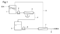
- the raw water in the raw water tank 1 is pressurized by the first pump 2 and supplied to the first first reverse osmosis membrane device 3, the concentrated water is discharged, and the permeated water is discharged by the pipe 4. Introduce into the intermediate tank 5.
- the water in the intermediate tank 5 is pressurized by the second pump 6 and supplied to the second-stage second reverse osmosis membrane device 7, the permeated water is taken out by the pipe 8, and the concentrated water is returned to the raw water tank 1 by the pipe 9. .
- the first-stage and second-stage reverse osmosis membrane devices 3 and 6 each have a spiral membrane element.
- the spiral type membrane element is a spiral type membrane element in which a bag-like separation membrane containing a permeated water spacer is wound on a water collecting pipe in a spiral shape by overlapping raw water spacers.
- FIG. 2 of Patent Document 3 using a spiral membrane element in which a shaft is used instead of a water collecting pipe, and a bag-like membrane having a permeate outlet is wound on a part of the side is wound around the shaft.
- not only a spiral type membrane element but also a flat membrane type element may be used.
- the thickness of the raw water spacer of the reverse osmosis membrane device is larger than 0.6 mm at the first stage and 0.6 mm or less at the second stage.
- the reverse osmosis membrane device is provided in two stages, but it may be provided in three or more stages.
- the thickness of the raw water spacers of the reverse osmosis membrane devices in the third and subsequent stages is 0.6 mm or less.
- the reverse osmosis membrane may be any of seawater desalination, low pressure, ultra low pressure, ultra ultra low pressure and the like.
- a material of a reverse osmosis membrane Any of cellulose acetate, polyamide, etc. may be sufficient, and what is necessary is just to select suitably according to the required removal rate and flux.
- a reverse osmosis membrane of an aromatic polyamide synthesized with phenylenediamine and acid chloride it is preferable to employ a reverse osmosis membrane of an aromatic polyamide synthesized with phenylenediamine and acid chloride.
- the raw water spacer As the raw water spacer, a plurality of wires made of a synthetic resin such as polyethylene or polypropylene and having the same or different diameters (wire diameters) are arranged at equal intervals and overlapped so as to intersect at an angle of 45 to 90 degrees.
- the mesh spacer formed by this can be used.
- the porosity of the raw water spacer is preferably 60% or more and 95% or less. Thereby, concentration polarization can be sufficiently suppressed by a sufficient stirring effect.
- the mesh size of the raw water spacer is preferably 1 mm or more and 4 mm or less. Thereby, concentration polarization can be suppressed by a sufficient stirring effect, and an increase in the channel resistance of the stock solution can be suppressed, and high separation membrane performance can be obtained.
- the raw water spacer is not limited to a mesh spacer. For example, it may be made of a zigzag wire as shown in FIG.
- the thickness of the raw water spacer of the first-stage reverse osmosis membrane device is larger than 0.6 mm, preferably 0.7 mm or more, in order to prevent turbid blockage. However, if the thickness of the raw water spacer is too large, concentration polarization increases and the removal rate decreases, so that the thickness is preferably 2.0 mm or less.
- the thickness of the raw water spacer of the reverse osmosis membrane device in the second and subsequent stages is 0.6 mm or less.
- FIG. 2 shows the degree of concentration polarization of NaCl in a spiral reverse osmosis membrane module having a diameter of 8 inches when raw water spacers of various thicknesses are used. As shown in FIG. 2, a spacer having a thickness of 0.6 mm or more has a large influence of concentration polarization, and the ratio of the membrane surface concentration to the average bulk concentration exceeds 1.2 times when the amount of concentrated water is 2 m 3 / h or more. It is not preferable. When the thickness of the raw water spacer is 0.6 mm or less, concentration polarization can be prevented and good treated water quality can be obtained.
- the thickness of the raw water spacer is less than 0.2 mm, the water flow resistance becomes too large, and therefore it is preferably 0.2 mm or more. Therefore, it is preferable that the thickness of the raw water spacer of the reverse osmosis membrane apparatus in the second and subsequent stages is 0.2 to 0.6 mm, particularly 0.2 to 0.5 mm, and particularly 0.3 to 0.5 mm.
- the thickness of the permeated water spacer installed in the bag-like membrane is not particularly limited, but is preferably 0.1 to 0.25 mm.
- the membrane area per element is reduced as in the raw water spacer, and when it is too thin, the differential pressure increases and the permeated water amount decreases.
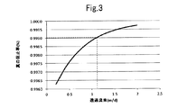
- the true rejection rate of NaCl depends on the permeation flux, and the true rejection rate increases as the permeation flux increases.
- the permeation flux of the second-stage reverse osmosis membrane device is preferably 1.1 to 2.0 m / d.
- the true removal rate exceeds 99.9% when it is 1.1 m / d or more, which is preferable in terms of improving water quality.
- An excessively small permeation flux is not preferable because the true rejection rate is lowered and the water quality is lowered. If it is 2.0 m / d or more, it is not preferable because of the problem of the pressure resistance of the membrane and the permeation resistance of permeated water becomes high.
- the true rejection rate varies depending on the substance to be removed, the true rejection rate of any substance depends on the permeation flux. Therefore, by increasing the true rejection rate in NaCl, High blocking rates can be obtained for other substances.
- the permeation flux of the first-stage reverse osmosis membrane device is preferably 0.2 to 1.0 m / d, and more preferably 0.6 to 0.8 m / d.
- the permeation flux is 1.0 m / d or more, the fouling and clogging speed of the membrane increases, and the cleaning frequency increases.
- the device must be stopped each time, which is not economical. If it is less than 0.2 m / d, the number of films increases, which is not economical.
- the raw water spacer 11 and the permeate spacer 12 are reversed in a space formed by combining acrylic flow path forming members 21, 22, 23 and SUS pressure-resistant reinforcing members 24, 25.
- the laminated membrane unit is held via the osmotic membrane 10.
- the raw water flows into the primary side of the reverse osmosis membrane 10 from the raw water inlet 13 and flows along the raw water spacer 11, and the permeated water that has permeated the reverse osmosis membrane 10 in the meantime passes through the permeated water spacer 12 and passes through the permeated water outlet 15. Taken from.
- the concentrated water is taken out from the concentrated water outlet 14.
- Example 1 Water obtained by flocculation and filtration of industrial water (TOC concentration 500 ppb (0.5 mg / L)) was used as raw water and passed through a multistage reverse osmosis membrane apparatus having the flow shown in FIG.
- a flat membrane is cut out from Nitto Denko's reverse osmosis membrane ES20 to a width of 50 mm and a length of 800 mm to obtain a thickness.
- a SUS water flow cell was filled as shown in FIG. 4 together with a 0.71 mm polypropylene raw water spacer (wire diameter 0.25 to 0.36 mm, mesh opening 2.6 mm).
- the second-stage reverse osmosis membrane device 7 also assumes the same reverse osmosis membrane element, and cuts a flat membrane from a reverse osmosis membrane ES20 manufactured by Nitto Denko into a width 50 mm ⁇ length 800 mm, and a polypropylene raw water spacer having a thickness of 0.60 mm (A wire diameter of 0.2 to 0.3 mm, an opening of 2.2 mm) was filled into a SUS water flow cell as shown in FIG.
- each membrane area 41.8M 2, a 46.0M 2.
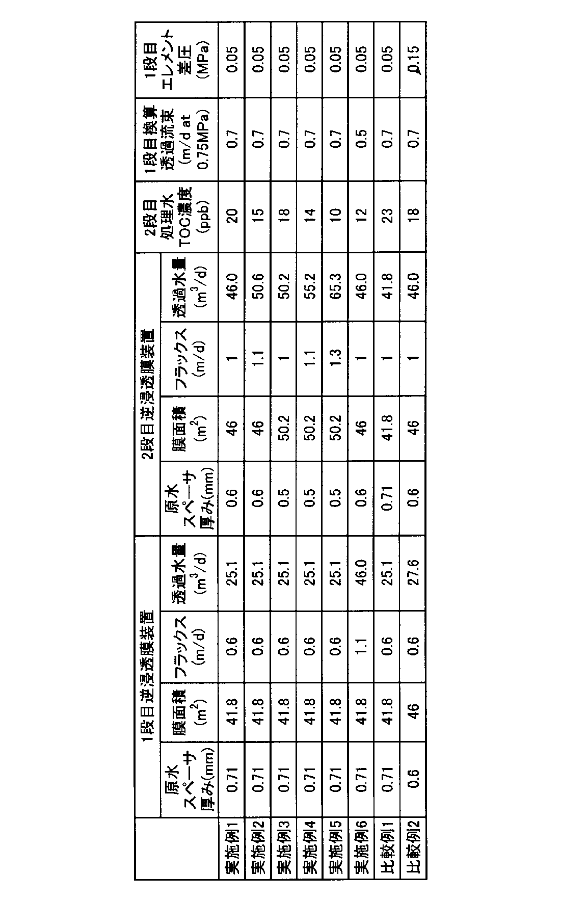
- Example 2 The test was performed under the same conditions as in Example 1 except that the permeation flux of the second-stage reverse osmosis membrane was 1.1 m / d. Table 1 shows the TOC concentration of treated water after 500 hours of water flow, the converted permeated water amount (permeated flow rate when converted to 0.75 MPa), and the differential pressure of the first stage element.
- Example 3 The test was performed under the same conditions as in Example 1 except that the raw water spacer of the second-stage reverse osmosis membrane was a wire having a diameter of 0.15 to 0.25 mm, an aperture of 2.0 mm, and a thickness of 0.5 mm. went. When this membrane element is filled in an 8-inch reverse osmosis membrane device, the membrane area is 50.2 m 2 .
- Table 1 shows the TOC concentration of treated water after 500 hours of water flow, the converted permeated water amount (permeated flow rate when converted to 0.75 MPa), and the differential pressure of the first stage element.
- Example 4 The test was performed under the same conditions as in Example 3 except that the permeation flux of the second-stage reverse osmosis membrane device was 1.1 m / d.
- Table 1 shows the TOC concentration of treated water after 500 hours of water flow, the converted permeated water amount (permeated flow rate when converted to 0.75 MPa), and the differential pressure of the first stage element.
- Example 5 The test was performed under the same conditions as in Example 3 except that the permeation flux of the second-stage reverse osmosis membrane was 1.3 m / d.
- Table 1 shows the TOC concentration of treated water after 500 hours of water flow, the converted permeated water amount (permeated flow rate when converted to 0.75 MPa), and the differential pressure of the first stage element.
- Example 6 The test was performed under the same conditions as in Example 1 except that the permeation flux of the first-stage reverse osmosis membrane was 1.1 m / d. Table 1 shows the TOC concentration of treated water after 500 hours of water flow, the converted permeated water amount (permeated flow rate when converted to 0.75 MPa), and the differential pressure of the first stage element.
- Example 1 The test was performed under the same conditions as in Example 1 except that the raw water spacer of the second-stage reverse osmosis membrane was a wire having a diameter of 0.25 to 0.36 mm, an aperture of 2.6 mm, and a thickness of 0.71 mm. Carried out. When this membrane element is filled in an 8-inch reverse osmosis membrane device, the membrane area is 41.8 m 2 .
- the treated water TOC concentration after 500 hours of water flow, the converted permeated water amount (permeated flow rate when converted to 0.75 MPa), and the differential pressure of the first stage element were measured. The results are shown in Table 1.
- Example 2 The test was performed under the same conditions as in Example 1, except that the raw water spacer of the first-stage reverse osmosis membrane was a wire diameter of 0.2 to 0.3 mm, an aperture of 2.2 mm, and a thickness of 0.6 mm. Carried out. When this membrane element is filled in an 8-inch reverse osmosis membrane device, the membrane area is 41.8 m 2 .
- the treated water TOC concentration after 500 hours of water flow, the converted permeated water amount (permeated flow rate when converted to 0.75 MPa), and the differential pressure of the first stage element were measured. The results are shown in Table 1.
- Example 6 As shown in Table 1, according to Examples 1 to 6, the treated water TOC concentration is low and high-purity water quality can be obtained. In Example 6, since the first stage permeation flux is higher than the other examples, a decrease is seen in the permeation flux after 500 hours. Comparative Example 1 is a conventional processing method. In Comparative Example 2, the quality of the treated water is better than before, but since the raw water spacer of the first-stage reverse osmosis membrane is thinned, the element differential pressure of the first-stage reverse osmosis membrane rises early and the stability is low.
- Example 7 Assuming a commercially available 8-inch reverse osmosis membrane element as a reverse osmosis membrane of the first-stage reverse osmosis membrane device 3, a flat membrane is cut out from Nitto Denko's reverse osmosis membrane ES20 to a width of 50 mm ⁇ length of 800 mm and a thickness of 0. A SUS water flow cell as shown in FIG. 4 was filled together with an 86 mm polypropylene raw water spacer (wire diameter: 0.3 to 0.43 mm, mesh opening: 3.0 mm).
- a flat membrane is cut out from Nitto Denko's reverse osmosis membrane ES20 to a width of 50 mm ⁇ length of 800 mm, and a polypropylene raw water spacer having a thickness of 0.60 mm (wire diameter 0.2) SUS water flow cell as shown in FIG.
- the membrane areas are 37.1 m 2 and 46.0 m 2 , respectively.
- the raw treated water was coagulated and filtered from biologically treated water (TOC concentration 1100 ppb (1.1 mg / L)). Water was passed to 3.6 m 3 / h, and water was passed through the second-stage reverse osmosis membrane device to a permeation flux of 1.0 m / d and 3.6 m 3 / h in terms of 8-inch elements.
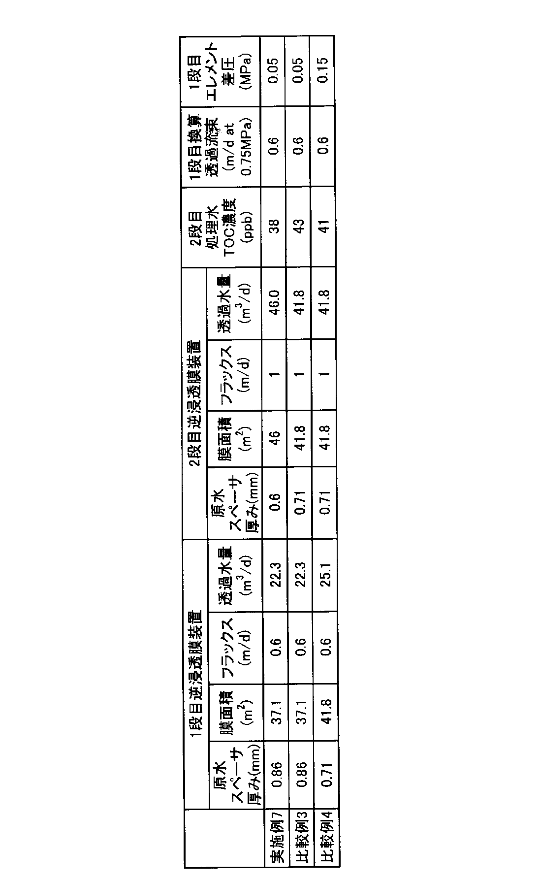
- Table 2 shows the TOC concentration of treated water after 500 hours of water flow, the converted permeated water amount (permeated flow rate when converted to 0.75 MPa), and the differential pressure of the first stage element.
- Example 3 The test was performed under the same conditions as in Example 7, except that the raw water spacer of the second-stage reverse osmosis membrane was a wire having a diameter of 0.25 to 0.36 mm, an aperture of 2.6 mm, and a thickness of 0.71 mm. went. When this membrane element is filled in an 8-inch reverse osmosis membrane device, the membrane area is 41.8 m 2 . Table 2 shows the TOC concentration of treated water after 500 hours of water flow, the converted permeated water amount (permeated flow rate when converted to 0.75 MPa), and the differential pressure of the first stage element.
- Comparative Example 4 The test was performed under the same conditions as in Comparative Example 3 except that the raw water spacer of the first-stage reverse osmosis membrane was a wire having a diameter of 0.25 to 0.36 mm, an aperture of 2.6 mm, and a thickness of 0.71 mm. went. When this membrane element is filled in an 8-inch reverse osmosis membrane device, the membrane area is 41.8 m 2 . Table 2 shows the TOC concentration of treated water after 500 hours of water flow, the converted permeated water amount (permeated flow rate when converted to 0.75 MPa), and the differential pressure of the first stage element.
- the multistage reverse osmosis membrane device of the present invention using the raw water spacer of the same thickness for the first and second stage reverse osmosis membrane devices.
- High-purity treated water can be obtained, and water quality can be improved without impairing stability.
Landscapes
- Chemical & Material Sciences (AREA)
- Engineering & Computer Science (AREA)
- Water Supply & Treatment (AREA)
- Chemical Kinetics & Catalysis (AREA)
- Life Sciences & Earth Sciences (AREA)
- Hydrology & Water Resources (AREA)
- Environmental & Geological Engineering (AREA)
- Organic Chemistry (AREA)
- Nanotechnology (AREA)
- Separation Using Semi-Permeable Membranes (AREA)
Abstract
Description
工業用水を凝集及び濾過した水(TOC濃度500ppb(0.5mg/L))を原水として用い、図1に示すフローの多段逆浸透膜装置に通水した。
2段目の逆浸透膜の透過流束を1.1m/dとしたこと以外は実施例1と同一の条件で試験を行った。通水500時間後の処理水TOC濃度と、換算透過水量(0.75MPa換算時の透過流量)及び1段目エレメントの差圧を表1に示す。
2段目の逆浸透膜の原水スペーサとして、線径0.15~0.25mm、目開き2.0mm、厚み0.5mmのものを用いたこと以外は実施例1と同一の条件で試験を行った。この膜エレメントを8インチ逆浸透膜装置に充填した場合、膜面積は50.2m2となる。通水500時間後の処理水TOC濃度、換算透過水量(0.75MPa換算時の透過流量)及び1段目エレメントの差圧を表1に示す。
2段目の逆浸透膜装置の透過流束を1.1m/dとしたこと以外は実施例3と同一の条件で試験を行った。通水500時間後の処理水TOC濃度、換算透過水量(0.75MPa換算時の透過流量)及び1段目エレメントの差圧を表1に示す。
2段目の逆浸透膜の透過流束を1.3m/dとしたこと以外は実施例3と同一の条件で試験を行った。通水500時間後の処理水TOC濃度、換算透過水量(0.75MPa換算時の透過流量)及び1段目エレメントの差圧を表1に示す。
1段目の逆浸透膜の透過流束を1.1m/dとしたこと以外は実施例1と同一の条件で試験を実施した。通水500時間後の処理水TOC濃度、換算透過水量(0.75MPa換算時の透過流量)及び1段目エレメントの差圧を表1に示す。
2段目の逆浸透膜の原水スペーサとして、線径0.25~0.36mm、目開き2.6mm、厚み0.71mmのものを用いたこと以外は実施例1と同一の条件で試験を実施した。この膜エレメントを8インチ逆浸透膜装置に充填した場合、膜面積は41.8m2となる。通水500時間後の処理水TOC濃度と、換算透過水量(0.75MPa換算時の透過流量)、及び1段目エレメントの差圧を測定した。結果を表1に示す。
1段目の逆浸透膜の原水スペーサとして、線径0.2~0.3mm、目開き2.2mm、厚み0.6mmのものを用いたこと以外は実施例1と同一の条件で試験を実施した。この膜エレメントを8インチ逆浸透膜装置に充填した場合、膜面積は41.8m2となる。通水500時間後の処理水TOC濃度と、換算透過水量(0.75MPa換算時の透過流量)、及び1段目エレメントの差圧を測定した。結果を表1に示す。
1段目の逆浸透膜装置3の逆浸透膜として、市販の8インチ逆浸透膜エレメントを想定し、日東電工製逆浸透膜ES20から平膜を幅50mm×長さ800mmに切り抜き、厚み0.86mmのポリプロピレン製原水スペーサ(線径0.3~0.43mm、目開き3.0mm)とともに図4の通りSUS製通水セルに充填した。
2段目の逆浸透膜の原水スペーサとして、線径0.25~0.36mm、目開き2.6mm、厚み0.71mmのものを用いたこと以外は実施例7と同一の条件で試験を行った。この膜エレメントを8インチ逆浸透膜装置に充填した場合、膜面積は41.8m2となる。通水500時間後の処理水TOC濃度、換算透過水量(0.75MPa換算時の透過流量)及び1段目エレメントの差圧を表2に示す。
1段目の逆浸透膜の原水スペーサとして、線径0.25~0.36mm、目開き2.6mm、厚み0.71mmのものを用いたこと以外は比較例3と同一の条件で試験を行った。この膜エレメントを8インチ逆浸透膜装置に充填した場合、膜面積は41.8m2となる。通水500時間後の処理水TOC濃度、換算透過水量(0.75MPa換算時の透過流量)及び1段目エレメントの差圧を表2に示す。
本出願は、2013年2月20日付で出願された日本特許出願2013-031033に基づいており、その全体が引用により援用される。
Claims (3)
- 袋状の逆浸透膜を原水スペーサと共に巻回してなるスパイラル型膜エレメントを備えた逆浸透膜装置を多段に設置してなり、前段の逆浸透膜装置の処理水を後段の逆浸透膜装置で処理する多段逆浸透膜装置において、
1段目の逆浸透膜装置の膜エレメントの原水スペーサの厚みが0.6mmより大きく、2段目以降の逆浸透膜装置の膜エレメントの原水スペーサの厚みが0.6mm以下であることを特徴とする多段逆浸透膜装置。 - 請求項1に記載の多段逆浸透膜装置において、1段目の逆浸透膜装置の原水スペーサの厚みが0.7~2mmであり、2段目以降の逆浸透膜装置の膜エレメントの原水スペーサの厚みが0.2~0.6mmであることを特徴とする多段逆浸透膜装置。
- 請求項1又は2に記載の多段逆浸透膜装置を運転する方法において、1段目の逆浸透膜装置の透過流束を1.0m/d以下とし、2段目以降の逆浸透膜装置の透過流束を1.1m/d以上とすることを特徴とする多段逆浸透膜装置の運転方法。
Priority Applications (4)
| Application Number | Priority Date | Filing Date | Title |
|---|---|---|---|
| KR1020157021770A KR102009550B1 (ko) | 2013-02-20 | 2014-02-14 | 다단 역침투막 장치 및 그 운전 방법 |
| CN201480009128.2A CN105073650B (zh) | 2013-02-20 | 2014-02-14 | 多段逆渗透膜装置及其运转方法 |
| SG11201506175QA SG11201506175QA (en) | 2013-02-20 | 2014-02-14 | Multi-stage reverse osmosis membrane system and operation method therefor |
| US14/766,334 US20150376034A1 (en) | 2013-02-20 | 2014-02-14 | Multi-stage reverse osmosis membrane system and operation method thereof |
Applications Claiming Priority (2)
| Application Number | Priority Date | Filing Date | Title |
|---|---|---|---|
| JP2013-031033 | 2013-02-20 | ||
| JP2013031033A JP5838981B2 (ja) | 2013-02-20 | 2013-02-20 | 多段逆浸透膜装置及びその運転方法 |
Publications (1)
| Publication Number | Publication Date |
|---|---|
| WO2014129399A1 true WO2014129399A1 (ja) | 2014-08-28 |
Family
ID=51391192
Family Applications (1)
| Application Number | Title | Priority Date | Filing Date |
|---|---|---|---|
| PCT/JP2014/053472 Ceased WO2014129399A1 (ja) | 2013-02-20 | 2014-02-14 | 多段逆浸透膜装置及びその運転方法 |
Country Status (7)
| Country | Link |
|---|---|
| US (1) | US20150376034A1 (ja) |
| JP (1) | JP5838981B2 (ja) |
| KR (1) | KR102009550B1 (ja) |
| CN (1) | CN105073650B (ja) |
| SG (1) | SG11201506175QA (ja) |
| TW (1) | TWI579245B (ja) |
| WO (1) | WO2014129399A1 (ja) |
Cited By (4)
| Publication number | Priority date | Publication date | Assignee | Title |
|---|---|---|---|---|
| CN107406994A (zh) * | 2015-03-10 | 2017-11-28 | 通用电气公司 | 具有多层支撑基材的离子交换膜 |
| WO2020066762A1 (ja) * | 2018-09-28 | 2020-04-02 | 三菱日立パワーシステムズ株式会社 | 水処理システム及び水処理方法 |
| CN115520934A (zh) * | 2021-06-25 | 2022-12-27 | 中国石油化工股份有限公司 | 膜分离回收系统和方法 |
| US11766638B2 (en) | 2017-03-20 | 2023-09-26 | Bl Technologies, Inc. | Ion-exchange membrane having an imprinted non-woven substrate |
Families Citing this family (8)
| Publication number | Priority date | Publication date | Assignee | Title |
|---|---|---|---|---|
| JP2016112518A (ja) * | 2014-12-16 | 2016-06-23 | 株式会社日立製作所 | 脱酸素装置及び脱酸素水製造方法 |
| JP7089352B2 (ja) * | 2016-09-16 | 2022-06-22 | 日東電工株式会社 | スパイラル型膜エレメント |
| JP6807219B2 (ja) * | 2016-11-18 | 2021-01-06 | オルガノ株式会社 | 逆浸透膜処理システムおよび逆浸透膜処理方法 |
| CN109867329A (zh) * | 2017-12-01 | 2019-06-11 | 北京京润环保科技股份有限公司 | 一种反渗透系统 |
| RU2701342C1 (ru) * | 2018-05-30 | 2019-09-27 | Общество с ограниченной ответственностью "7 Тех" | Способ обессоливания воды методом обратного осмоса и устройство для его осуществления |
| KR102770593B1 (ko) * | 2019-03-22 | 2025-02-19 | 주식회사 엘지화학 | 고회수율 역삼투 스페이서 및 엘리먼트 |
| GB201912458D0 (en) * | 2019-08-30 | 2019-10-16 | Fujifilm Mfg Europe Bv | Gas seperations elements and modules |
| CN110723784B (zh) * | 2019-10-16 | 2022-04-15 | 东莞市鸾江水处理设备工程有限公司 | 一种废水处理回收方法 |
Citations (6)
| Publication number | Priority date | Publication date | Assignee | Title |
|---|---|---|---|---|
| JPH10230143A (ja) * | 1997-02-19 | 1998-09-02 | Nitto Denko Corp | スパイラル型膜エレメントを用いた処理システムおよび処理方法 |
| JP2000237554A (ja) * | 1999-02-18 | 2000-09-05 | Nitto Denko Corp | スパイラル型膜エレメント |
| JP2000262867A (ja) * | 1999-03-17 | 2000-09-26 | Toray Ind Inc | 逆浸透膜分離装置および水の分離方法 |
| JP2006507919A (ja) * | 2002-05-02 | 2006-03-09 | フィルムテック コーポレーション | 改良された供給スペーサーをもつ螺旋状に巻かれた部材 |
| JP2007152265A (ja) * | 2005-12-07 | 2007-06-21 | Toray Ind Inc | 淡水製造装置の運転方法および淡水製造装置 |
| JP2007523744A (ja) * | 2004-02-25 | 2007-08-23 | ダウ グローバル テクノロジーズ インコーポレーテッド | 高い浸透力の溶液を処理する装置 |
Family Cites Families (9)
| Publication number | Priority date | Publication date | Assignee | Title |
|---|---|---|---|---|
| WO1993022038A1 (en) * | 1992-05-01 | 1993-11-11 | Filmtec Corporation | Spiral wound membrane element |
| JPH1157429A (ja) | 1997-08-18 | 1999-03-02 | Kurita Water Ind Ltd | スパイラル型膜モジュール |
| JP2000261867A (ja) * | 1999-03-11 | 2000-09-22 | Takaoka Electric Mfg Co Ltd | 遠方監視システムの通信方式 |
| JP2002001069A (ja) | 2000-06-21 | 2002-01-08 | Kurita Water Ind Ltd | 純水製造方法 |
| JP2004089761A (ja) | 2002-08-29 | 2004-03-25 | Japan Organo Co Ltd | スパイラル型膜エレメント、逆浸透膜モジュール及び逆浸透膜装置 |
| US8216473B2 (en) * | 2008-06-13 | 2012-07-10 | Solution Dynamics, Llc | Apparatus and methods for solution processing using reverse osmosis |
| JP5383163B2 (ja) | 2008-11-27 | 2014-01-08 | 三菱重工業株式会社 | 多段海水淡水化装置及び多段海水淡水化装置の運転制御方法 |
| KR20110076872A (ko) * | 2008-11-28 | 2011-07-06 | 가부시키가이샤 신꼬오 간쿄우 솔루션 | 담수 생성 방법, 담수 생성 장치, 해수 담수화 방법 및 해수 담수화 장치 |
| US20120061300A1 (en) * | 2010-09-15 | 2012-03-15 | Takeshi Matsushiro | Membrane filtration system |
-
2013
- 2013-02-20 JP JP2013031033A patent/JP5838981B2/ja active Active
-
2014
- 2014-02-14 SG SG11201506175QA patent/SG11201506175QA/en unknown
- 2014-02-14 US US14/766,334 patent/US20150376034A1/en not_active Abandoned
- 2014-02-14 CN CN201480009128.2A patent/CN105073650B/zh active Active
- 2014-02-14 WO PCT/JP2014/053472 patent/WO2014129399A1/ja not_active Ceased
- 2014-02-14 KR KR1020157021770A patent/KR102009550B1/ko active Active
- 2014-02-19 TW TW103105410A patent/TWI579245B/zh active
Patent Citations (6)
| Publication number | Priority date | Publication date | Assignee | Title |
|---|---|---|---|---|
| JPH10230143A (ja) * | 1997-02-19 | 1998-09-02 | Nitto Denko Corp | スパイラル型膜エレメントを用いた処理システムおよび処理方法 |
| JP2000237554A (ja) * | 1999-02-18 | 2000-09-05 | Nitto Denko Corp | スパイラル型膜エレメント |
| JP2000262867A (ja) * | 1999-03-17 | 2000-09-26 | Toray Ind Inc | 逆浸透膜分離装置および水の分離方法 |
| JP2006507919A (ja) * | 2002-05-02 | 2006-03-09 | フィルムテック コーポレーション | 改良された供給スペーサーをもつ螺旋状に巻かれた部材 |
| JP2007523744A (ja) * | 2004-02-25 | 2007-08-23 | ダウ グローバル テクノロジーズ インコーポレーテッド | 高い浸透力の溶液を処理する装置 |
| JP2007152265A (ja) * | 2005-12-07 | 2007-06-21 | Toray Ind Inc | 淡水製造装置の運転方法および淡水製造装置 |
Cited By (5)
| Publication number | Priority date | Publication date | Assignee | Title |
|---|---|---|---|---|
| CN107406994A (zh) * | 2015-03-10 | 2017-11-28 | 通用电气公司 | 具有多层支撑基材的离子交换膜 |
| US11766638B2 (en) | 2017-03-20 | 2023-09-26 | Bl Technologies, Inc. | Ion-exchange membrane having an imprinted non-woven substrate |
| WO2020066762A1 (ja) * | 2018-09-28 | 2020-04-02 | 三菱日立パワーシステムズ株式会社 | 水処理システム及び水処理方法 |
| CN115520934A (zh) * | 2021-06-25 | 2022-12-27 | 中国石油化工股份有限公司 | 膜分离回收系统和方法 |
| CN115520934B (zh) * | 2021-06-25 | 2024-05-03 | 中国石油化工股份有限公司 | 膜分离回收系统和方法 |
Also Published As
| Publication number | Publication date |
|---|---|
| JP2014159016A (ja) | 2014-09-04 |
| JP5838981B2 (ja) | 2016-01-06 |
| CN105073650B (zh) | 2017-04-19 |
| TWI579245B (zh) | 2017-04-21 |
| KR20150118951A (ko) | 2015-10-23 |
| TW201500295A (zh) | 2015-01-01 |
| CN105073650A (zh) | 2015-11-18 |
| SG11201506175QA (en) | 2015-09-29 |
| KR102009550B1 (ko) | 2019-08-09 |
| US20150376034A1 (en) | 2015-12-31 |
Similar Documents
| Publication | Publication Date | Title |
|---|---|---|
| JP5838981B2 (ja) | 多段逆浸透膜装置及びその運転方法 | |
| EP3357559B1 (en) | Reverse osmosis filter module | |
| JP5828328B2 (ja) | 逆浸透膜装置の運転方法、及び逆浸透膜装置 | |
| JP2000271460A (ja) | スパイラル型膜モジュールを用いた処理システムおよび処理方法 | |
| US10583401B2 (en) | Integrated ultrafiltration and reverse osmosis desalination systems | |
| JP4251879B2 (ja) | 分離膜モジュールの運転方法 | |
| JP6183213B2 (ja) | 造水方法および造水装置 | |
| JP2004050005A (ja) | スパイラル型膜エレメント、逆浸透膜モジュール及び逆浸透膜装置 | |
| JP3230490B2 (ja) | スパイラル型逆浸透膜エレメントおよびそれを用いた分離装置 | |
| JP2538409B2 (ja) | 低圧用逆浸透膜による高濃度溶液の濃縮方法及び装置 | |
| JP2004261724A (ja) | 多段式分離膜モジュールの運転方法及び多段式分離膜装置 | |
| JP7133429B2 (ja) | 水処理システム及び水処理方法 | |
| WO2016027302A1 (ja) | 逆浸透膜装置及びその運転方法 | |
| Yaranal et al. | An analysis of the effects of pressure-assisted osmotic backwashing on the high recovery reverse osmosis system | |
| WO2015002015A1 (ja) | 膜分離装置の運転方法及び膜分離システム | |
| JP2015226864A (ja) | 正浸透用中空糸膜モジュール | |
| KR20170023626A (ko) | 수처리용 트리코트 여과수로 및 이를 포함하는 수처리용 역삼투압 필터 모듈 | |
| JP2005046762A (ja) | 水処理方法および装置 | |
| JP2006218341A (ja) | 水処理方法および装置 | |
| Sarfraz | Recent trends in membrane processes for water purification of brackish water | |
| JP2001252662A (ja) | 造水方法 | |
| JP2019514665A (ja) | 逆浸透フィルタモジュール | |
| JP2023096360A (ja) | 水処理方法および水処理装置 | |
| CN113518657A (zh) | 高回收率反渗透间隔件和元件 | |
| JP2001252661A (ja) | 造水方法 |
Legal Events
| Date | Code | Title | Description |
|---|---|---|---|
| WWE | Wipo information: entry into national phase |
Ref document number: 201480009128.2 Country of ref document: CN |
|
| 121 | Ep: the epo has been informed by wipo that ep was designated in this application |
Ref document number: 14754665 Country of ref document: EP Kind code of ref document: A1 |
|
| WWE | Wipo information: entry into national phase |
Ref document number: 14766334 Country of ref document: US |
|
| ENP | Entry into the national phase |
Ref document number: 20157021770 Country of ref document: KR Kind code of ref document: A |
|
| NENP | Non-entry into the national phase |
Ref country code: DE |
|
| 122 | Ep: pct application non-entry in european phase |
Ref document number: 14754665 Country of ref document: EP Kind code of ref document: A1 |