WO2014129284A1 - 脱穀装置 - Google Patents
脱穀装置 Download PDFInfo
- Publication number
- WO2014129284A1 WO2014129284A1 PCT/JP2014/052121 JP2014052121W WO2014129284A1 WO 2014129284 A1 WO2014129284 A1 WO 2014129284A1 JP 2014052121 W JP2014052121 W JP 2014052121W WO 2014129284 A1 WO2014129284 A1 WO 2014129284A1
- Authority
- WO
- WIPO (PCT)
- Prior art keywords
- insertion direction
- net
- fixed
- handling
- frame
- Prior art date
- Legal status (The legal status is an assumption and is not a legal conclusion. Google has not performed a legal analysis and makes no representation as to the accuracy of the status listed.)
- Ceased
Links
Images








Classifications
-
- A—HUMAN NECESSITIES
- A01—AGRICULTURE; FORESTRY; ANIMAL HUSBANDRY; HUNTING; TRAPPING; FISHING
- A01F—PROCESSING OF HARVESTED PRODUCE; HAY OR STRAW PRESSES; DEVICES FOR STORING AGRICULTURAL OR HORTICULTURAL PRODUCE
- A01F7/00—Threshing apparatus
- A01F7/02—Threshing apparatus with rotating tools
- A01F7/06—Threshing apparatus with rotating tools with axles in line with the feeding direction ; Axial threshing machines
-
- A—HUMAN NECESSITIES
- A01—AGRICULTURE; FORESTRY; ANIMAL HUSBANDRY; HUNTING; TRAPPING; FISHING
- A01F—PROCESSING OF HARVESTED PRODUCE; HAY OR STRAW PRESSES; DEVICES FOR STORING AGRICULTURAL OR HORTICULTURAL PRODUCE
- A01F12/00—Parts or details of threshing apparatus
- A01F12/18—Threshing devices
- A01F12/185—Mounting means
-
- A—HUMAN NECESSITIES
- A01—AGRICULTURE; FORESTRY; ANIMAL HUSBANDRY; HUNTING; TRAPPING; FISHING
- A01F—PROCESSING OF HARVESTED PRODUCE; HAY OR STRAW PRESSES; DEVICES FOR STORING AGRICULTURAL OR HORTICULTURAL PRODUCE
- A01F12/00—Parts or details of threshing apparatus
- A01F12/18—Threshing devices
- A01F12/22—Threshing cylinders with teeth
-
- A—HUMAN NECESSITIES
- A01—AGRICULTURE; FORESTRY; ANIMAL HUSBANDRY; HUNTING; TRAPPING; FISHING
- A01F—PROCESSING OF HARVESTED PRODUCE; HAY OR STRAW PRESSES; DEVICES FOR STORING AGRICULTURAL OR HORTICULTURAL PRODUCE
- A01F12/00—Parts or details of threshing apparatus
- A01F12/18—Threshing devices
- A01F12/26—Multi-part threshing concaves
Definitions
- the present invention relates to a threshing apparatus.
- the threshing apparatus described in Patent Document 1 is already known.
- the receiving net is divided into three along the circumferential direction of the barrel, and three nets (in the literature, “first divided receiving network”, “second divided receiving network”, “ The third divided receiving network ”).
- the threshing apparatus described in Patent Document 1 from the third divided receiving network on the innermost side in the insertion direction among the three mesh bodies, in the order of the second divided receiving network and the first divided receiving network, from the left side of the handling chamber It is inserted sequentially.
- the end on the front side in the insertion direction in the second divided receiving network and the end on the back side in the insertion direction in the first divided receiving network are connected by bolts, and the front in the insertion direction in the first divided receiving network.
- the end on the side is fixed to the chamber frame with bolts.
- the handling cylinder described in Patent Document 2 is already known.
- a first support plate in the literature, a flange member
- a second support plate in the literature, a flange member
- a plurality of rod-like members are arranged on a circumference centered on the handling cylinder axis. The front end portion of the rod-shaped member is supported by the first support plate, and the rear end portion of the rod-shaped member is supported by the second support plate.
- a substantially circular partition plate (in the literature, a flange member) is provided between the first support plate and the second support plate in the handling cylinder shaft.
- the partition plate supports between the front end portions and the rear end portions of the plurality of rod-shaped members.
- the present invention has been made in view of the above situation, and an object of the present invention is to provide a threshing apparatus capable of easily fixing a plurality of nets constituting a receiving net to a handling room frame.
- the present invention has been made in view of the above circumstances, and an object thereof is to provide a handling cylinder capable of reducing the weight and cost of the handling cylinder by reducing the size of the partition plate.
- a feature of the present invention includes a handling chamber in which a handling cylinder is provided, a handling chamber frame that forms the handling chamber, and a receiving net provided below the handling cylinder, and the receiving net is provided on the handling cylinder. It has a plurality of nets divided along the circumferential direction and sequentially inserted from one side of the handling chamber, and each of the plurality of nets is fixed to the handling chamber frame individually. .
- an end portion on the front side in the insertion direction is fixed to the handling chamber frame.
- the end on the near side in the insertion direction in the mesh body on the back side in the insertion direction is the first fixture.
- inner side in the net body of the said insertion direction near side is fixed to the said handling chamber flame
- inner side In a state where the net body and the net body on the front side in the insertion direction are fixed to the handling chamber frame, the second fixing tool at the end on the back side in the insertion direction in the net body on the front side in the insertion direction.
- the plurality of fixing points are arranged so as to sandwich the fixing points by the first fixing tool at the end portion on the front side in the insertion direction in the net body on the back side in the insertion direction in the axial direction of the handling cylinder. It is preferable that
- the net body on the back side in the insertion direction and the net body on the front side in the insertion direction are connected to the handle cylinder. It can be stably fixed to the chamber frame over the axial direction.
- the plurality of nets are configured to be used together.
- the cost can be reduced by sharing the parts.
- the plurality of mesh bodies are configured by the same member, and in each of the plurality of mesh bodies, the fixing portion of the end portion on the near side in the insertion direction and the end portion on the back side in the insertion direction are arranged. It is preferable that the fixed portion is arranged at a different position in the axial direction of the handling cylinder.
- the end of the end on the near side in the insertion direction is inserted. Since the fixed portion and the fixed portion at the end on the far side in the insertion direction are arranged at different positions in the axial direction of the handling cylinder, the net body cannot be fixed to the handling chamber frame. Therefore, the net body is not fixed to the handling chamber frame in a state where the end on the near side in the insertion direction is mistaken with the end on the far side in the insertion direction.
- the chamber frame has a side frame that extends in the front-rear direction at one side of the chamber, and is inserted into the network body on the foremost side in the insertion direction among the plurality of mesh bodies.
- a flange portion is formed at an end portion on the front side in the direction, and a fixing portion as a portion fixed to the side frame is formed on the flange portion, and the thickness of the fixing portion portion of the flange portion is It is preferable that the flange portion is thicker than the thickness of the portion other than the fixed portion.
- the thickness of the fixed portion of the flange portion is thicker than the thickness of the portion other than the fixed portion, the strength of the fixed portion is improved. Even if it is pulled in the rotational direction, the fixed portion is not easily deformed.
- the fixing portion is formed by overlapping a plate on the flange portion.
- the fixing portion can be easily formed simply by overlapping the plate on the flange portion.
- the plurality of nets are configured to be used in combination with each other, the flange portions are formed at both ends in the insertion direction in each of the plurality of nets, and among the plurality of nets In the two mesh bodies adjacent to each other in the insertion direction, the end on the back side in the insertion direction of the net on the front side in the insertion direction is overlapped with the end on the near side in the insertion direction in the net body on the back side in the insertion direction.
- the second fixing tool is fixed to the handling frame with the end portion on the front side in the insertion direction in the net body on the back side in the insertion direction, and the fixing section is fixed to the side with the third fixing tool.
- the fixing portion is formed only in the lunge portion, and the plate is inserted into the second insertion hole through which the second fixing tool is not inserted in any one of the flange portions of each of the plurality of mesh bodies. It is preferable to block.
- the posture in which the net on the foremost side in the insertion direction is the end on the front side in the insertion direction is correctly the flange on which the plates of the two flanges are overlapped.
- the plug is mistakenly inserted in a posture that is the end on the back side in the insertion direction.
- the second insertion hole of the flange portion on which the plates are overlapped out of both flange portions Since it is blocked by the plate, the second fixture cannot be inserted into the second insertion hole.
- the chamber frame has a side frame that extends in the front-rear direction at one side of the chamber, and is inserted into the network body on the foremost side in the insertion direction among the plurality of mesh bodies.
- a flange portion is formed at an end portion on the front side in the direction, and a fixing portion is formed on the flange portion as a portion fixed to the side frame, and an end portion on the free end side of the flange portion is fixed. It is preferable to be formed so as to be bent with respect to the part.
- the end of the free end side of the flange portion is bent with respect to the fixed portion, so that the strength of the portion of the fixed portion is improved. Therefore, the receiving net is pulled in the rotation direction of the barrel. However, the fixed part is not easily deformed.
- a feature of the present invention is that a handling shaft, a first support plate provided on one end side of the handling shaft, a second support plate provided on the other end side of the handling shaft, and one end portion of the first support plate
- a plurality of teeth handling teeth each provided in plurality, and provided between the first support plate and the second support plate on the handle barrel shaft, and between one end and the other end of the plurality of rod-shaped members
- the partition plate can be reduced in size. Therefore, the size of the partition plate can reduce the weight of the handling cylinder. If it does so, in the combine provided with such a handling cylinder, since a threshing load reduces, a fuel consumption improves. Moreover, since the material which comprises a partition plate reduces by size reduction of a partition plate, a cost reduction is attained.
- the rod-shaped member is supported by the partition plate in a state of being radially spaced from the outer periphery of the partition plate.
- the partition plate has a perfect circle shape.
- the partition plate can be easily manufactured by simplifying the shape of the partition plate.
- the interval between the plurality of teeth handling teeth is different between adjacent rod-shaped members among the plurality of rod-shaped members.
- the first support plate has a substantially circular shape, and the diameter of the partition plate is smaller than the diameter of the first support plate.
- one end of the rod-shaped member can be reliably supported by the first support plate while the partition plate is downsized.
- the second support plate is substantially circular and the diameter of the partition plate is smaller than the diameter of the second support plate.
- the other end of the rod-shaped member can be reliably supported by the second support plate while the partition plate is downsized.
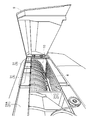
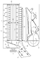
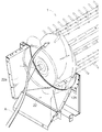
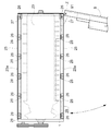
- FIG. 1 It is side surface sectional drawing which shows the threshing apparatus which concerns on 1st embodiment of this invention. It is a perspective view which shows the left side part of a threshing apparatus. It is a top view which shows the state by which the net body was fixed to the chamber frame. It is a top view which shows two right and left net bodies.
- A It is Va-Va sectional drawing in FIG.
- B It is Vb-Vb sectional drawing in FIG.
- C It is Vc-Vc sectional drawing in FIG.
- B It is an expansion perspective sectional view which shows an upper flange part.
- (B) It is a perspective sectional view showing the state where the lower flange part in the right net is fixed to the center frame.
- (A) It is a rear view which shows the state by which the net body of the left side is fixed to the chamber frame.
- (B) It is a perspective sectional view showing the state where the lower flange part in the left net is fixed to the central frame.
- (B) It is a perspective sectional view showing the state where the upper flange part in the left net is fixed to the left side frame.
- Sectional drawing which shows the net
- the threshing apparatus shown in FIG. 1 is mounted on a combine that harvests crops such as rice and wheat.
- the threshing device threshs the harvested cereal.
- the threshing device mounted on the ordinary combine is provided with the handling cylinder 1.
- a handling chamber 2 is formed in the upper part of the threshing apparatus.
- a handling cylinder 1 for threshing treatment is provided in the handling chamber 2 so as to be rotatable around a longitudinal axis Y.
- a receiving net 3 is provided below the handling cylinder 1, for leaking a processed product (threshing processed product) obtained by the threshing process.
- An opening 10 covered with an openable / closable threshing opening / closing cover 9 is formed on the left side of the handling chamber 2 (see FIG. 2).
- a swing sorting device 4 for swing sorting and a tang 5 for wind sorting.
- a first recovery unit 6 for recovering the first grain
- a second recovery unit 7 for recovering the second grain in order from the front.
- the most recovery unit 6 is provided with the most transverse screw 6A that conveys the grain in the left-right direction.
- the second recovery unit 7 is provided with a second horizontal screw 7A that conveys the grains in the left-right direction.
- the harvested cereal meal is threshed by the barrel 1 and the processed product (threshing processed product) obtained by the threshing process leaks from the receiving net 3. Then, the threshing processed material leaked from the receiving net 3 is subjected to swing sorting by the swing sorting device 4 and wind sorting by the Kara 5. Thereby, the single grain with a large specific gravity is collected as the first thing in the first collection unit 6 at the front, and the grain with a branch branch with a small specific gravity is collected as the second product in the second collection unit 7 at the rear. Collected.
- the receiving net 3 is divided into two along the circumferential direction of the handling cylinder 1 and into two along the axis Y direction of the handling cylinder 1. That is, the receiving network 3 has four net bodies 31.
- the four net members 31 are composed of the same member that can be used together. Each of the four nets 31 is sequentially inserted from the opening 10 formed on the left side of the handling chamber 2. That is, in this embodiment, the “insertion direction” of the net body 31 is the left-right direction. Therefore, in the present embodiment, the “back side in the insertion direction” means the right side, and the “front side in the insertion direction” means the left side. In addition, although mentioned later in detail, each of the four net bodies 31 is being fixed to the chamber frame 21 separately.
- the handling chamber frame 21 forms the handling chamber 2.
- the handling frame 21 includes a left side frame 21A (corresponding to a “side frame” according to the present invention), a right side frame 21B, and a center frame 21C.
- the left side frame 21 ⁇ / b> A extends in the front-rear direction on the left side of the handling chamber 2.
- the right side frame 21 ⁇ / b> B extends in the front-rear direction on the right side of the handling chamber 2.
- the central frame 21 ⁇ / b> C extends in the front-rear direction at a substantially central portion on the left and right sides of the handling chamber 2.
- the two left and right mesh bodies 31 on the rear side and the two left and right mesh bodies 31 on the front side have the same configuration. And the two left and right nets 31 on the front side will be described as necessary.
- the left end of the right net 31 is fixed to the central frame 21C with a first bolt 32 (corresponding to the “first fixture” according to the present invention). ing.
- the right end of the right net 31 is not fixed to the right frame 21B with bolts or the like. That is, the right end of the right net 31 is only addressed to the lower surface of the right frame 21B.
- the right end of the left net 31 is superimposed on the left end of the right net 31 and It is fixed to the central frame 21 ⁇ / b> C by a second bolt 33 (corresponding to a “second fixing tool” according to the present invention) together with the end.
- the left end of the left net 31 is fixed to the left frame 21A with a third bolt 34 (corresponding to a “third fixture” according to the present invention).
- the net body 31 alone will be described in detail.
- the net body 31 includes five struts 31 ⁇ / b> Aa, 31 ⁇ / b> Ab, 31 ⁇ / b> Ac, 31 ⁇ / b> Ad, and 31 ⁇ / b> Ae that are arranged at predetermined intervals in the axis Y direction of the handling cylinder 1.
- the upper ends of the five columns 31Aa, 31Ab, 31Ac, 31Ad, and 31Ae are connected by an upper flange portion 31B.
- the lower ends of the five columns 31Aa, 31Ab, 31Ac, 31Ad, 31Ae are connected by a lower flange portion 31C.
- a plurality of round bars 31D are arranged at predetermined intervals in the direction of the axis Y of the handling cylinder 1 between two adjacent columns among the five columns 31Aa, 31Ab, 31Ac, 31Ad, and 31Ae. Since the upper flange portion 31B and the lower flange portion 31C have the same configuration except for the fixing portion 31I in the upper flange portion 31B, the upper flange portion 31B will be mainly described below, and the lower flange portion 31C will be described. Will be described as necessary.
- the upper flange portion 31B has one first bolt hole 31E, two second bolt holes 31F (corresponding to a “second insertion hole” according to the present invention), and a third bolt hole 31G (according to the present invention. 2) and one notch 31 ⁇ / b> H (corresponding to “recess” according to the present invention) are formed.
- the first bolt hole 31E can be inserted through the first bolt 32.
- the first bolt hole 31 ⁇ / b> E is disposed between the two second bolt holes 31 ⁇ / b> F in the axis Y direction of the handling cylinder 1.
- the second bolt hole 31F can be inserted through the second bolt 33.
- the two second bolt holes 31F are arranged so as to sandwich the first bolt hole 31E from both sides in the axial center Y direction of the handling cylinder 1.
- the third bolt hole 31G allows the third bolt 34 to be inserted therethrough.
- the two third bolt holes 31 ⁇ / b> G are arranged so as to sandwich the two second bolt holes 31 ⁇ / b> F from both sides in the axis Y direction of the handling cylinder 1.
- the notch 31H is formed at the end on the free end side of the upper flange portion 31B.
- the notch 31H is disposed between the two second bolt holes 31F in the direction of the axis Y of the handling cylinder 1.
- the notch 31H is larger than the first bolt 32 (the head of the first bolt 32).
- the upper flange portion 31B is formed with a fixing portion 31I as a portion fixed to the left side frame 21A.
- the fixing portion 31I is fixed to the left side frame 21A with the third bolt 34.
- the lower flange portion 31C is not formed with a portion corresponding to the fixing portion 31I in the upper flange portion 31B. That is, the fixed portion 31I is formed only in the upper flange portion 31B among the upper flange portion 31B and the lower flange portion 31C.
- the thickness of the portion of the fixed portion 31I in the upper flange portion 31B is thicker than the thickness of the portion of the upper flange portion 31B other than the fixed portion 31I.
- the fixed portion 31I is formed by overlapping the plate 31J on the upper flange portion 31B.
- the plate 31J closes the second bolt hole 31F through which the second bolt 33 is not inserted in the upper flange portion 31B.
- the plate 31J is not overlaid on the lower flange portion 31C.
- the right net 31 of the two left and right nets 31 on the rear side is inserted from the left side (opening 10) of the handling chamber 2.
- the lower flange portion 31 ⁇ / b> C in the right mesh body 31 is fixed to the center frame 21 ⁇ / b> C with the first bolt 32.
- the lower flange portion 31C in the right net 31 is fixed to the central frame 21C with the first bolt 32 in a state where the lower flange portion 31C is addressed to the left side surface of the central frame 21C.
- the first bolt 32 is inserted into the first bolt hole 31E of the lower flange portion 31C in the right mesh body 31.
- the upper flange portion 31B of the right mesh body 31 is only addressed to the lower surface of the right side frame 21B and is not fixed to the right side frame 21B with bolts or the like.
- the left net 31 of the two left and right nets 31 on the rear side is inserted from the left side (opening 10) of the handling chamber 2.
- the lower flange portion 31C in the left mesh body 31 is overlapped with the lower flange portion 31C in the right mesh body 31, and the second bolt 33 and the center portion are connected together with the lower flange portion 31C in the right mesh body 31. It is fixed to the frame 21C.
- the second bolt 33 is inserted into the second bolt hole 31F of the lower flange portion 31C in the left mesh body 31 and the second bolt hole 31F of the lower flange portion 31C in the right mesh body 31.
- the lower flange 31C in the left mesh 31 is connected to the right mesh 31. Even if they are overlapped with the lower flange portion 31 ⁇ / b> C, the lower flange portion 31 ⁇ / b> C in the left net 31 does not interfere with the first bolt 32.
- the upper flange portion 31 ⁇ / b> B in the left net 31 is fixed to the left frame 21 ⁇ / b> A with the third bolt 34.
- the upper flange portion 31B of the left net 31 is fixed to the left frame 21A with the third bolt 34 in a state where the upper flange portion 31B is addressed to the lower surface of the left frame 21A.
- the third bolt 34 is inserted into the third bolt hole 31G of the upper flange portion 31B in the left net 31.
- the two fixing locations (second bolt holes 31 ⁇ / b> F) of the lower flange portion 31 ⁇ / b> C and the two fixing locations (two third bolt holes 31 ⁇ / b> G) of the upper flange portion 31 ⁇ / b> B are 1 are arranged at different positions in the axis Y direction (see FIG. 3).
- the two bolt holes 31F) sandwich one fixing point (one first bolt hole 31E) by the first bolt 32 of the lower flange portion 31C in the right net 31 in the axial center Y direction of the handling cylinder 1 from both sides.
- the upper flange portion 31B on which the plate 31J of the upper flange portion 31B and the lower flange portion 31C is overlapped is correctly the end portion on the far side in the insertion direction (right end). It is conceivable that it is inserted in a posture that becomes the end (left end) on the front side in the insertion direction by mistake. In this regard, even when the right mesh body 31 is inserted in an incorrect posture, the first bolt 32 is inserted into the first bolt hole 31E of the upper flange portion 31B of the right mesh body 31, thereby the right mesh body 31 being inserted.
- the upper flange portion 31 ⁇ / b> B in the body 31 is fixed to the central frame 21 ⁇ / b> C with the first bolt 32.
- the right mesh body 31 when the right mesh body 31 is inserted in a wrong posture, the lower flange portion 31C of the left mesh body 31 is overlapped with the upper flange portion 31B of the right mesh body 31, and the right mesh body 31 is placed. Even if the second bolt 33 and the upper flange portion 31B are fixed to the center frame 21C, the second bolt hole 31F of the upper flange portion 31B in the right mesh body 31 is closed by the plate 31J. The two bolts 33 cannot be inserted into the second bolt hole 31F. Therefore, at this time, it is noticed that the right net 31 is inserted in an incorrect posture. That is, it is possible to reliably prevent the right net body 31 from being fixed to the handling chamber frame 21 in an incorrect posture.
- the upper flange portion 31B on which the plate 31J of the upper flange portion 31B and the lower flange portion 31C is overlapped is correctly the end portion (left end portion) on the front side in the insertion direction. ) May be inserted in a posture that becomes an end (right end) on the far side in the insertion direction by mistake.
- the mesh body 31 when the mesh body 31 is inserted in the wrong posture on the left side, the upper mesh portion 31B of the left mesh body 31 is overlapped with the lower flange portion 31C of the right mesh body 31, and the right mesh body 31 is placed. Even if the second bolt 33 and the lower flange portion 31C are fixed to the center frame 21C, the second bolt hole 31F of the upper flange portion 31B in the left net 31 is closed by the plate 31J. The two bolts 33 cannot be inserted into the second bolt hole 31F. Therefore, at this time, it is noticed that the left net 31 is inserted in an incorrect posture. That is, it is possible to reliably prevent the left net 31 from being fixed to the handling chamber frame 21 in an incorrect posture.
- the fixing method of the mesh body 31 has been described by taking the left and right two mesh bodies 31 on the rear side of the four mesh bodies 31 as an example, but the fixing method of the two left and right mesh bodies 31 on the front side is also the rear. This is the same procedure as the fixing method of the two left and right nets 31 on the side.
- the plate 31J is a substantially rectangular plate-like member.
- the plate 31J is superimposed on the lower surface of the upper flange portion 31B in a posture in which the longitudinal direction is the front-rear direction and the short direction is the left-right direction.
- the plate 31J is formed with a bolt hole 31Ja, a first notch groove 31Jb, and a second notch groove 31Jc.
- the bolt hole 31Ja can be inserted through the third bolt 34.
- the first notch groove 31Jb and the second notch groove 31Jc are notched from one long side (the long side inside the machine body of the pair of long sides) to the short side direction (the machine body outer direction) of the plate 31J.
- the distance D1 between the center of the bolt hole 31Ja and the front and rear center of the first notch groove 31Jb and the distance D2 between the center of the bolt hole 31Ja and the front and rear center of the second notch groove 31Jc are set to different distances. . Specifically, the distance D1 is set larger than the distance D2.
- the two third bolt holes 31G and the columns 31Ab and 31Ad in the upper flange portion 31B will be described.
- the left net body 31 of the two left and right net bodies 31 will be described, but the same applies to the other net bodies 31.
- the center line in the front-rear direction (center line between the front end P1 and the rear end P2 of the net 31) is a center line C
- the front-side third bolt hole 31G and the rear-side third bolt hole 31G are arranged at positions symmetrical with respect to the center line C. That is, the distance between the center of the front third bolt hole 31G and the center line C and the distance between the center of the rear third bolt hole 31G and the center line C are set to the same distance D3.
- the column 31Ab and the column 31Ad are disposed at positions that are asymmetrical with respect to the center line C. That is, the distance D4 between the front and rear center of the support 31Ab and the center line C and the distance D5 between the front and rear center of the support 31Ad and the center line C are set to different distances. Specifically, the distance D4 is set larger than the distance D5.
- the distance between the center of the third bolt hole 31G on the front side and the front-rear center of the support 31Ab is set to a distance D2. That is, the distance D2 between the center of the bolt hole 31Ja in the plate 31J and the front-rear center of the second notch groove 31Jc is set to be the same as the distance D2 between the center of the front third bolt hole 31G and the front-rear center of the column 31Ab. Yes.
- the distance between the center of the rear third bolt hole 31G and the front-rear center of the column 31Ad is set to the distance D1. That is, the distance D1 between the center of the bolt hole 31Ja in the plate 31J and the longitudinal center of the first notch 31Jb is set to be the same as the distance D1 between the center of the rear third bolt hole 31G and the longitudinal center of the column 31Ad. Has been.
- the front-side third bolt hole 31G and the rear-side third bolt hole 31G are arranged at positions symmetrical with respect to the center line C. Therefore, the net body 31 can be fixed in a well-balanced manner by the third bolt 34 inserted through the two front and rear third bolt holes 31G.
- the front plate and the rear plate of the upper flange portion 31B are dedicated plates, respectively. There is no need to prepare. That is, when the plate 31J is used for the front portion of the upper flange portion 31B, the plate 31J and the column 31Ab do not interfere with each other by inserting the column 31Ab into the second notch groove 31Jc. On the other hand, when the plate 31J is used for the rear portion of the upper flange portion 31B, the plate 31J and the column 31Ad do not interfere with each other by allowing the column 31Ad to enter the first groove 31Jb. This eliminates the need to prepare dedicated plates for the front portion and the rear portion of the upper flange portion 31B, so that the cost can be reduced by sharing the plate 31J.
- the “insertion direction” of the mesh body 31 is the left-right direction, but the “insertion direction” of the mesh body 31 may be the front-rear direction.
- the receiving net 3 is divided into two parts along the circumferential direction of the handling cylinder 1, but the receiving net 3 may be divided into three or more parts along the circumferential direction of the handling cylinder 1. Good.
- the above-described configuration (fixed by the first bolt 32 and the second bolt 33) can be adopted between the two mesh bodies 31 adjacent in the insertion direction.
- the receiving net 3 is divided into two along the axis Y direction of the handling cylinder 1, but the receiving net 3 is arranged in the axis Y direction of the handling cylinder 1. Even if it is divided into three or more along, it does not need to be divided along the axis Y direction of the barrel 1.
- the receiving network 3 includes four network bodies 31, but the receiving network 3 may include two, three, or five or more network bodies 31.
- the plate 31J is superimposed on the upper flange portion 31B of the mesh body 31, but as shown in FIG. 10, the end on the free end side of the upper flange portion 31B is fixed. It may be formed so as to be bent with respect to the portion 31I. That is, the free end side end portion of the upper flange portion 31B may be formed in a substantially L shape.
- the second bolt 33 fastens and fixes the lower flange portion 31C of the left mesh 31 and the lower flange portion 31C of the right mesh 31 to the center frame 21C.
- the second bolt 33 does not fasten and fix the lower flange portion 31C of the left mesh 31 and the lower flange portion 31C of the right mesh 31 to the central frame 21C (each separately attached to the central frame 21C). (Fixed).
- the “concave portion” is configured by the notch portion 31 ⁇ / b> H, but the “concave portion” may be configured by a recess or hole larger than the first bolt 32.
- the plurality of nets 31 are configured to be used in combination with each other, but the plurality of nets 31 may not be configured to be used in combination with each other.
- the number of fixing points by the first bolts 32 in the mesh body 31, that is, the first bolt holes 31E is one, but the number of the first bolt holes 31E may be two or more.
- the number of fixing points by the second bolts 33 in the mesh body 31, that is, the second bolt holes 31F is two, but the number of the second bolt holes 31F may be one or three or more. .
- the number of fixing points by the third bolts 34 in the mesh body 31, that is, the third bolt holes 31G are two, but the number of the third bolt holes 31G may be one or three or more. .
- the fixing portion 31I is formed on the upper flange portion 31B of the mesh body 31, but the fixing portion 31I is not formed on the upper flange portion 31B of the mesh body 31. Good.
- the upper flange portion 31B and the lower flange portion 31C are the same, the upper flange portion 31B can also be used as the lower flange portion, and the lower flange portion 31C can be used as the upper flange portion. You can also.
- the fixed portion 31I is formed by overlapping the plate 31J on the upper flange portion 31B of the mesh body 31, but the fixed portion 31I is formed integrally with the upper flange portion 31B. May be.
- a threshing inlet 121 into which a harvested cereal meal is carried is formed at the front lower end of the handling chamber 2.
- the harvested cereal meal is carried into the threshing inlet 121 by the feeder 8 (see FIG. 11).
- a threshing inlet plate 22 is attached to the threshing inlet 121.
- the right side wall 22 a of the threshing inlet plate 22 is formed in a shape that gradually (smoothly) extends from the outlet of the feeder 8 to the diameter of the handling cylinder 1.
- an opening 10 covered with a threshing opening / closing cover 9 that can be opened and closed is formed on the left side of the handling chamber 2.
- the rear end portion of the threshing open / close cover 9 is supported via a swing shaft 91 so as to be swingable about a vertical axis Z.
- the front part inside the threshing opening / closing cover 9 is provided with an inclined part 92 that inclines outward.
- the height of the outer end portion of the inclined portion 92 is set to coincide with or substantially coincide with the height of the lower edge portion 10a of the opening portion 10 in a state where the threshing opening / closing cover 9 is closed.
- the threshing opening / closing cover 9 when the threshing opening / closing cover 9 is tilted forward and under its own weight, the threshing opening / closing cover 9 is displaced with respect to the opening 10, so that it may be difficult to close the threshing opening / closing cover 9.
- the inclined portion 92 gradually moves to the lower edge portion 10a of the opening 10 in conjunction with closing the threshing opening / closing cover 9.
- the threshing opening / closing cover 9 is moved forward by climbing on. Thereby, since the threshing opening / closing cover 9 is positioned in the opening 10, the threshing opening / closing cover 9 does not become difficult to close.
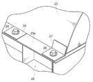
- the upper portion of the handling cylinder 1 is detachably covered with a threshing top plate 23.
- Attachment portions 23 a are formed on the left and right ends of the threshing top plate 23.
- the attaching part 23a is being fixed to the side plate 25 which forms the side part of a threshing apparatus with the six bolts 26 (refer FIG. 15).
- a reinforcing L plate 27 is welded to a portion of the six bolts 26 fixed by the rearmost bolt 26 in the mounting portion 23a.
- the portion is fixed to the side plate 25 with a bolt 26 in a state where the L plate 27 is welded.
- a reinforcing flat plate 28 is welded to a portion of the six bolts 26 that is fixed by the five bolts 26 excluding the rearmost bolt 26 in the mounting portion 23a.
- the portion is fixed to the side plate 25 with a bolt 26 in a state where the flat plate 28 is welded.
- an upward force acts on the threshing top plate 23
- the attachment portion 23 a is fixed to the side plate 25 with the bolts 26 in a state where the L plate 27 and the flat plate 28 are reinforced.
- the durability of the mounting portion 23a can be improved.
- the handling cylinder 1 corresponds to the handling cylinder shaft 11, a front support plate 12 (corresponding to a “first support plate”), and a rear support plate 13 (corresponding to a “second support plate”). ), A plurality of round pipes 14 (corresponding to “bar-shaped members”), a plurality of teeth 15 and a partition plate 16.
- the handling cylinder shaft 11 is constructed over the front wall of the handling chamber 2 and the rear wall of the handling chamber 2.
- the front end portion of the handling cylinder shaft 11 is rotatably supported by the front wall of the handling chamber 2, and the rear end portion of the handling cylinder shaft 11 is rotatably supported by the rear wall of the handling chamber 2.
- a screw 17 is provided on the front side of the front support plate 12 to feed the harvested cereal meal into the threshing inlet 121.
- the front support plate 12 is provided on the front end side of the barrel 11.
- the front support plate 12 is formed in a perfect circle shape or a substantially circular shape.
- the diameter of the front support plate 12 is larger than the rotation locus L of the portion closest to the barrel shaft 11 in the cross section of the round pipe 14.
- the cross section of the round pipe 14 means a cross section in a direction orthogonal to the axial center direction of the round pipe 14 (the same applies hereinafter).
- the front support plate 12 supports the front end portion of the round pipe 14. Specifically, the front support plate 12 supports the front end portion of the round pipe 14 via a front support stay 14a.
- the front support stay 14a is fixed to the front end portion of the round pipe 14 by welding or other fixing methods.
- the front support stay 14 a is fixed to the front support plate 12 with two bolts 18.
- the rear support plate 13 is provided on the rear end side of the handling cylinder shaft 11.
- the rear support plate 13 is formed in a perfect circle shape or a substantially circular shape.
- the diameter of the rear support plate 13 is larger than the rotation locus L of the portion closest to the barrel 11 in the cross section of the round pipe 14.
- the rear support plate 13 supports a rear end portion of the round pipe 14. Specifically, the rear end portion of the round pipe 14 is supported on the rear support plate 13 via the rear support stay 14b.
- the rear support stay 14b is fixed to the rear end portion of the round pipe 14 by welding or other fixing methods.
- the rear support stay 14 b is fixed to the rear support plate 13 with two bolts 18.
- the plurality of round pipes 14 are arranged on a circumference around the barrel shaft 11.
- the plurality of round pipes 14 is six. Specifically, the six round pipes 14 are arranged at equiangular intervals on a circumference centered on the handle shaft 11.
- the round pipe 14 is supported by the partition plate 16 in a state of being spaced radially outward from the outer periphery of the partition plate 16. That is, the round pipe 14 is supported by the partition plate 16 via the intermediate support stay 14 c in a state where a gap G is formed between the outer periphery of the partition plate 16 and the round pipe 14.
- the intermediate support stay 14c is a flat plate-like member in which a fitting recess is formed.
- the fitting recess is formed in a substantially semicircular shape that fits with the outer half of the round pipe 14.
- the intermediate support stay 14c is fixed to the round pipe 14 by welding or another fixing method in a state where the round pipe 14 is fitted in the fitting recess.
- the intermediate support stay 14 c is fixed to the partition plate 16 with a single bolt 18. Specifically, the intermediate support stay 14 c is fixed with bolts 18 from the rear of the partition plate 16 in a state of being applied to the front surface of the partition plate 16.
- a plurality of teeth 15 are provided on each of the six round pipes 14.
- the intervals between the plurality of teeth 15 are different among the adjacent round pipes 14 among the six round pipes 14.
- three round pipes 14 are provided with tooth handling teeth 15 at equal intervals D6, and the remaining three round pipes 14 are provided with tooth handling teeth 15 from the distance D6.
- the partition plate 16 is provided between the front support plate 12 and the rear support plate 13 on the handling shaft 11. Specifically, the partition plate 16 is provided in the middle or substantially the middle of the front support plate 12 and the rear support plate 13 on the handling cylinder shaft 11. Further, the partition plate 16 supports between the front end portion and the rear end portion of the round pipe 14. Specifically, the partition plate 16 supports a central portion or a substantially central portion of the round pipe 14 in the axial center direction.
- the partition plate 16 is formed in a substantially circular shape. Specifically, the partition plate 16 is formed in a perfect circle shape. The diameter of the partition plate 16 is smaller than the rotation locus L of the portion closest to the handle shaft 11 in the cross section of the round pipe 14. The diameter of the partition plate 16 is smaller than the diameter of the front support plate 12 and smaller than the diameter of the rear support plate 13.
- the partition plate 16 is disposed between adjacent teeth 15 among the teeth 15 in the direction of the axis Y of the barrel 11. That is, the partition plate 16 is disposed between the teeth 15 disposed at the interval D1 and between the teeth 15 disposed at the interval D2 in the axial center Y direction of the barrel 11. ing.
- the partition plate 16 can be downsized. Therefore, the handling cylinder 1 can be reduced in weight by reducing the size of the partition plate 16. If it does so, in the combine provided with such a handling cylinder 1, since a threshing load reduces, a fuel consumption improves. Moreover, since the material which comprises the partition plate 16 reduces by size reduction of the partition plate 16, cost reduction is attained.
- the number of the round pipes 14 is six, but the number of the round pipes 14 may be five or less, or seven or more.
- the partition plate 16 has a perfect circle shape, but the partition plate 16 may have a substantially circular shape in which some unevenness is formed in the radial direction.
- the round pipe 14 has a perfect circular cross section, but the round pipe 14 may have a substantially circular cross section.
- the “bar-shaped member” is the round pipe 14, but the “bar-shaped member” may be a square pipe.
- the intervals between the plurality of teeth 15 are different among the adjacent round pipes 14 among the six circle pipes 14, but the intervals between the plurality of teeth 15 are six circles. It may be the same in the pipe 14.
- the present invention can be used for a threshing apparatus.
- Handling cylinder 2 treatment room 3
- Receiving network 11
- Handling shaft 12
- Front support plate (first support plate) 13
- Rear support plate (second support plate) 14
- Round pipe (bar-shaped member) 15
- Teeth handling 16
- Partition plate 21
- Handling frame 21A Left side frame (side frame) 31 mesh
- Upper flange (flange) 31C
- Lower flange (flange) 31F
- Second bolt hole (second insertion hole) 31G Third bolt hole (third insertion hole) 31H Notch (recess) 31I fixed part
- 31J plate 32
- First bolt (first fixture) 33
- Second bolt (second fixture) 34
- Third bolt (third fixture) L rotation trajectory Y axis
Landscapes
- Life Sciences & Earth Sciences (AREA)
- Environmental Sciences (AREA)
- Threshing Machine Elements (AREA)
Abstract
Description
特許文献1に記載の脱穀装置において、第2分割受網及び第3分割受網は、第1分割受網を介して、扱室フレームに固定されている。したがって、第2分割受網及び第3分割受網を差し込んだ後、第1分割受網をボルトで扱室フレームに固定するまでは、第2分割受網及び第3分割受網が扱室フレームに固定されていないため、第2分割受網及び第3分割受網を手で支えておく必要がある。このように第2分割受網及び第3分割受網を手で支えながら、第1分割受網をボルトで扱室フレームに固定する作業は、容易でない。
本発明は以上の如き状況に鑑みてなされたものであり、受網を構成する複数の網体を扱室フレームに容易に固定することができる脱穀装置を提供することを目的とする。
特許文献2に記載の扱胴では、仕切板外周の嵌合凹部に棒状部材を嵌合させることにより、仕切板に棒状部材を支持させている。このため、仕切板の径が棒状部材の断面における最も扱胴軸に近い部分の回転軌跡よりも大きくなる。したがって、仕切板の大型化により、扱胴の重量化を招くことになる。そうすると、このような扱胴を備えたコンバインにおいては、脱穀負荷が増加するため、燃費の悪化が懸念される。また、仕切板の大型化により、仕切板を構成する材料が増加するため、コストアップとなる。
本発明は以上の如き状況に鑑みてなされたものであり、仕切板の小型化による扱胴の軽量化及びコストダウンが可能な扱胴を提供することを目的とする。
[1]課題[1]に対応する解決手段は以下の通りである。
本発明の特徴は、扱胴が設けられる扱室と、前記扱室を形成する扱室フレームと、前記扱胴の下方に設けられる受網と、を備え、前記受網は、前記扱胴の周方向に沿って分割され、前記扱室の一側部から順次差し込まれる複数の網体を有し、複数の前記網体の夫々は、各別に前記扱室フレームに固定されていることにある。
本特徴構成によれば、複数の網体の夫々を各別に扱室フレームに固定することにより、複数の網体を扱室フレームに容易に固定することができる。つまり、複数の網体のうち一の網体を手で支えながら、他の網体を扱室フレームに固定する作業を必要としない。
さらに、本発明において、複数の前記網体のうち差込方向最奥側の網体において、その差込方向手前側の端部が前記扱室フレームに固定されていると好適である。
本特徴構成によれば、差込方向最奥側の網体であっても、差込方向手前側の端部であれば、扱室の一側部から手が届き易いため、差込方向最奥側の網体を扱室フレームに容易に固定することができる。
差込方向に隣り合う二つの網体において、先ず、差込方向奥側の網体における差込方向手前側の端部が、第一固定具で扱室フレームに固定される。次に、差込方向手前側の網体における差込方向奥側の端部が、差込方向奥側の網体における差込方向手前側の端部に重ね合わされた状態で、差込方向奥側の網体における差込方向手前側の端部と共に第二固定具で扱室フレームに固定される。このとき、本特徴構成によれば、差込方向手前側の網体における差込方向奥側の端部に、第一固定具よりも大きい凹部が形成されていることにより、差込方向手前側の網体における差込方向奥側の端部を、差込方向奥側の網体における差込方向手前側の端部に重ね合わせても、差込方向手前側の網体における差込方向奥側の端部が、第一固定具と干渉することがない。
さらに、本発明において、前記差込方向手前側の網体における差込方向奥側の端部は、前記第二固定具によって複数箇所で前記扱室フレームに固定され、前記差込方向奥側の網体と前記差込方向手前側の網体とが前記扱室フレームに固定された状態において、前記差込方向手前側の網体における差込方向奥側の端部の前記第二固定具による複数の固定箇所は、前記扱胴の軸心方向において、前記差込方向奥側の網体における差込方向手前側の端部の前記第一固定具による固定箇所を両側から挟むように配置されていると好適である。
本特徴構成によれば、第二固定具による複数の固定箇所の間隔を大きくとることができるため、差込方向奥側の網体と、差込方向手前側の網体とを、扱胴の軸心方向に亘って扱室フレームに安定的に固定することができる。
さらに、本発明において、複数の前記網体は、互いに兼用可能に構成されていると好適である。
本特徴構成によれば、部品の共通化により、コストダウンが可能になる。
さらに、本発明において、複数の前記網体は、同一部材で構成され、複数の前記網体の夫々において、差込方向手前側の端部の固定箇所と、差込方向奥側の端部の固定箇所とは、前記扱胴の軸心方向における異なる位置に配置されていると好適である。
本特徴構成によれば、仮に、差込方向手前側の端部と差込方向奥側の端部とを取り違えた状態で、網体を差し込んだ場合でも、差込方向手前側の端部の固定箇所と、差込方向奥側の端部の固定箇所とが、扱胴の軸心方向における異なる位置に配置されていることから、網体を扱室フレームに固定することができない。したがって、差込方向手前側の端部と差込方向奥側の端部とを取り違えた状態で、網体が扱室フレームに固定されることがない。
さらに、本発明において、前記扱室フレームは、前記扱室の一側部で前後方向に延びる側部フレームを有し、複数の前記網体のうち差込方向最手前側の網体における差込方向手前側の端部に、フランジ部が形成され、前記フランジ部に、前記側部フレームに固定される部分としての固定部が形成され、前記フランジ部のうち前記固定部の部分の厚さは、前記フランジ部のうち前記固定部以外の部分の厚さよりも厚いと好適である。
本特徴構成によれば、フランジ部のうち固定部の部分の厚さが、固定部以外の部分の厚さよりも厚いことにより、固定部の部分の強度が向上するため、受網が扱胴の回転方向に引っ張られても、固定部が変形し難い。
さらに、本発明において、前記フランジ部にプレートが重ね合わせられることにより、前記固定部が形成されていると好適である。
本特徴構成によれば、フランジ部にプレートを重ね合わせるだけで、簡単に固定部を形成することができる。
さらに、本発明において、複数の前記網体は、互いに兼用可能に構成され、複数の前記網体の夫々における差込方向の両端部に、前記フランジ部が形成され、複数の前記網体のうち差込方向に隣り合う二つの網体において、差込方向手前側の網体における差込方向奥側の端部は、差込方向奥側の網体における差込方向手前側の端部に重ね合わせされた状態で、前記差込方向奥側の網体における差込方向手前側の端部と共に第二固定具で前記扱室フレームに固定され、前記固定部は、第三固定具で前記側部フレームに固定され、複数の前記網体の夫々における両フランジ部に、前記第二固定具を挿通可能な第二挿通孔と、前記第三固定具を挿通可能な第三挿通孔と、が形成され、複数の前記網体の夫々における両フランジ部のうち何れか一方のフランジ部のみに、前記固定部が形成され、前記プレートは、複数の前記網体の夫々における両フランジ部のうち何れか一方のフランジ部において、前記第二固定具を挿通しない前記第二挿通孔を塞いでいると好適である。
本特徴構成によれば、差込方向最手前側の網体を、両フランジ部のうちプレートが重ね合わせられている方のフランジ部が、正しくは、差込方向手前側の端部となる姿勢で差し込むべきところ、誤って、差込方向奥側の端部となる姿勢で差し込んでしまうことが考えられる。しかし、本特徴構成によれば、差込方向最手前側の網体を誤った姿勢で差し込んだ場合、両フランジ部のうちプレートが重ね合わせられている方のフランジ部の第二挿通孔は、プレートで塞がれているため、第二固定具を第二挿通孔に挿通することができない。したがって、この時点で、差込方向最手前側の網体を誤った姿勢で差し込んだことに気付くことになる。すなわち、差込方向最手前側の網体が誤った姿勢で扱室フレームに固定されるのを確実に防止することができる。
さらに、本発明において、前記扱室フレームは、前記扱室の一側部で前後方向に延びる側部フレームを有し、複数の前記網体のうち差込方向最手前側の網体における差込方向手前側の端部に、フランジ部が形成され、前記フランジ部に、前記側部フレームに固定される部分としての固定部が形成され、前記フランジ部における遊端側の端部は、前記固定部に対して屈曲するように形成されていると好適である。
本特徴構成によれば、フランジ部における遊端側の端部が固定部に対して屈曲することにより、固定部の部分の強度が向上するため、受網が扱胴の回転方向に引っ張られても、固定部が変形し難い。
本発明の特徴は、扱胴軸と、前記扱胴軸の一端部側に設けられる第一支持板と、前記扱胴軸の他端部側に設けられる第二支持板と、一端部が前記第一支持板に支持され、かつ、他端部が前記第二支持板に支持され、前記扱胴軸を中心とする円周上に配置される複数の棒状部材と、複数の前記棒状部材の夫々に複数ずつ設けられる複数の扱歯と、前記扱胴軸において前記第一支持板と前記第二支持板との間に設けられ、複数の前記棒状部材の一端部と他端部との間を支持する略円形状の仕切板と、を備え、前記仕切板の径は、前記棒状部材の断面における最も前記扱胴軸に近い部分の回転軌跡よりも小さいことにある。
本特徴構成によれば、仕切板の小型化が可能となる。したがって、仕切板の小型化により、扱胴の軽量化が可能となる。そうすると、このような扱胴を備えたコンバインにおいては、脱穀負荷が減少するため、燃費が向上する。また、仕切板の小型化により、仕切板を構成する材料が減少するため、コストダウンが可能となる。
本特徴構成によれば、仕切板の外周と棒状部材との間の隙間に手を入れ易いため、棒状部材を仕切板に支持させる際に作業がし易い。
さらに、本発明において、前記仕切板は、真円形状であると好適である。
本特徴構成によれば、仕切板の形状の簡素化により、仕切板の製造が容易になる。
さらに、本発明において、前記扱胴軸の軸心方向において、前記仕切板は、複数の前記扱歯のうち隣り合う前記扱歯同士の間に配置されていると好適である。
本特徴構成によれば、棒状部材を仕切板に支持させる際に、扱歯が邪魔になり難い。
さらに、本発明において、複数の前記扱歯の間隔は、複数の前記棒状部材のうち隣り合う前記棒状部材同士で異なると好適である。
本特徴構成によれば、脱穀負荷の増加を抑制しつつ扱胴の脱穀性能を向上させるべく、扱歯同士の間隔が大きい棒状部材と、扱歯同士の間隔が小さい棒状部材とを交互に配置させた扱胴においても、棒状部材を仕切板に支持させる際に、扱歯が邪魔になり難い。
さらに、本発明において、前記第一支持板は、略円形状であり、前記仕切板の径は、前記第一支持板の径よりも小さいと好適である。
本特徴構成によれば、仕切板を小型化しつつも、棒状部材の一端部を第一支持板で確実に支持することができる。
さらに、本発明において、前記第二支持板は、略円形状であり、前記仕切板の径は、前記第二支持板の径よりも小さいと好適である。
本特徴構成によれば、仕切板を小型化しつつも、棒状部材の他端部を第二支持板で確実に支持することができる。
以下、本発明の第一実施形態について図面に基づき説明する。
先ず、脱穀装置の全体構成について、図1及び図2により説明する。
図1に示す脱穀装置は、稲や麦等の作物を収穫するコンバインに搭載される。脱穀装置は、刈取穀稈を脱穀するものである。本実施形態では、普通型コンバインに搭載された脱穀装置に、扱胴1が備えられた形態を想定している。
脱穀装置の上部には、扱室2が形成されている。扱室2には、脱穀処理用の扱胴1が前後向きの軸心Y周りに回転可能に設けられている。扱胴1の下方には、脱穀処理で得られた処理物(脱穀処理物)を漏下させる受網3が設けられている。扱室2の左側部には、開閉可能な脱穀開閉カバー9で覆われた開口部10が形成されている(図2参照)。
脱穀装置の下部には、揺動選別用の揺動選別装置4、及び風選別用の唐箕5が設けられている。唐箕5の後方には、前方から順に、一番物の穀粒を回収する一番回収部6、及び二番物の穀粒を回収する二番回収部7が設けられている。一番回収部6には、穀粒を左右方向に搬送する一番横スクリュー6Aが設けられている。二番回収部7には、穀粒を左右方向に搬送する二番横スクリュー7Aが設けられている。
脱穀装置では、刈取穀稈が扱胴1で脱穀処理され、脱穀処理で得られた処理物(脱穀処理物)が受網3から漏下する。そして、受網3から漏下した脱穀処理物に対して、揺動選別装置4による揺動選別及び唐箕5による風選別が施される。これにより、比重が大きい単粒化穀粒は、前方の一番回収部6に一番物として回収され、比重が小さい枝梗付き穀粒は、後方の二番回収部7に二番物として回収される。
次に、受網3について、図3から図6により説明する。
図3から図6に示すように、受網3は、扱胴1の周方向に沿って二分割され、かつ、扱胴1の軸心Y方向に沿って二分割されている。つまり、受網3は、四つの網体31を有している。
四つの網体31は、互いに兼用可能な同一部材で構成されている。四つの網体31の夫々は、扱室2の左側部に形成された開口部10から順次差し込まれる。つまり、本実施形態において、網体31の「差込方向」は、左右方向である。したがって、本実施形態において、「差込方向奥側」とは、右側を意味し、「差込方向手前側」とは、左側を意味する。なお、詳しくは後述するが、四つの網体31の夫々は、各別に扱室フレーム21に固定されている。
扱室フレーム21は、扱室2を形成するものである。扱室フレーム21は、左側部フレーム21A(本発明に係る「側部フレーム」に相当)と、右側部フレーム21Bと、中央部フレーム21Cと、を備えている。左側部フレーム21Aは、扱室2の左側部で前後方向に延びている。右側部フレーム21Bは、扱室2の右側部で前後方向に延びている。中央部フレーム21Cは、扱室2の左右略中央部で前後方向に延びている。
なお、四つの網体31のうち、後側における左右二つの網体31と前側における左右二つの網体31とは、同一の構成であるため、以下では、後側における左右二つの網体31について主に説明し、前側における左右二つの網体31については、必要に応じて説明する。
後側における左右二つの網体31のうち、右側の網体31における左側の端部は、第一ボルト32(本発明に係る「第一固定具」に相当)で中央部フレーム21Cに固定されている。なお、右側の網体31における右側の端部は、右側部フレーム21Bにボルト等で固定されていない。つまり、右側の網体31における右側の端部は、右側部フレーム21Bの下面に宛がわれているだけである。
後側における左右二つの網体31のうち、左側の網体31における右側の端部は、右側の網体31における左側の端部に重ね合わせされた状態で、右側の網体31における左側の端部と共に第二ボルト33(本発明に係る「第二固定具」に相当)で中央部フレーム21Cに固定されている。また、左側の網体31における左側の端部は、第三ボルト34(本発明に係る「第三固定具」に相当)で左側部フレーム21Aに固定されている。
ここで、網体31単体について、詳しく説明する。図6に示すように、網体31は、扱胴1の軸心Y方向に所定の間隔をあけて配置される五つの支柱31Aa・31Ab・31Ac・31Ad・31Aeを備えている。五つの支柱31Aa・31Ab・31Ac・31Ad・31Aeの上端部は、上フランジ部31Bで連結されている。五つの支柱31Aa・31Ab・31Ac・31Ad・31Aeの下端部は、下フランジ部31Cで連結されている。五つの支柱31Aa・31Ab・31Ac・31Ad・31Aeのうち隣り合う二つの支柱の間には、複数の丸棒31Dが扱胴1の軸心Y方向に所定の間隔をあけて配置されている。なお、上フランジ部31Bと下フランジ部31Cとは、上フランジ部31Bにおける固定部31Iを除いては同一の構成であるため、以下では、上フランジ部31Bについて主に説明し、下フランジ部31Cについては、必要に応じて説明する。
上フランジ部31Bには、第一ボルト孔31Eが一つ、第二ボルト孔31F(本発明に係る「第二挿通孔」に相当)が二つ、第三ボルト孔31G(本発明に係る「第三挿通孔」に相当)が二つ、及び切欠部31H(本発明に係る「凹部」に相当)が一つ形成されている。
第一ボルト孔31Eは、第一ボルト32を挿通可能なものである。第一ボルト孔31Eは、扱胴1の軸心Y方向において二つの第二ボルト孔31Fの間に配置されている。
第二ボルト孔31Fは、第二ボルト33を挿通可能なものである。二つの第二ボルト孔31Fは、扱胴1の軸心Y方向において第一ボルト孔31Eを両側から挟むように配置されている。
第三ボルト孔31Gは、第三ボルト34を挿通可能なものである。二つの第三ボルト孔31Gは、扱胴1の軸心Y方向において二つの第二ボルト孔31Fを両側から挟むように配置されている。
切欠部31Hは、上フランジ部31Bにおける遊端側の端部に形成されている。切欠部31Hは、扱胴1の軸心Y方向において二つの第二ボルト孔31Fの間に配置されている。切欠部31Hは、第一ボルト32(第一ボルト32の頭部)よりも大きい。
上フランジ部31Bには、左側部フレーム21Aに固定される部分としての固定部31Iが形成されている。固定部31Iは、第三ボルト34で左側部フレーム21Aに固定される。なお、下フランジ部31Cには、上フランジ部31Bにおける固定部31Iに相当する部分が形成されていない。つまり、上フランジ部31B及び下フランジ部31Cのうち上フランジ部31Bのみに、固定部31Iが形成されている。
上フランジ部31Bのうち固定部31Iの部分の厚さは、上フランジ部31Bのうち固定部31I以外の部分の厚さよりも厚い。本実施形態では、上フランジ部31Bにプレート31Jが重ね合わせられることにより、固定部31Iが形成されている。プレート31Jは、上フランジ部31Bにおいて、第二ボルト33を挿通しない第二ボルト孔31Fを塞いでいる。なお、上述のように、下フランジ部31Cには、上フランジ部31Bにおける固定部31Iに相当する部分が形成されていないため、下フランジ部31Cには、プレート31Jが重ね合わせられていない。
次に、網体31の固定方法について、図7から図9により説明する。なお、以下では、四つの網体31のうち後側における左右二つの網体31を例として、網体31の固定方法について説明する。
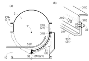
先ず、図7に示すように、後側における左右二つの網体31のうち右側の網体31が、扱室2の左側部(開口部10)から差し込まれる。そして、右側の網体31における下フランジ部31Cが、第一ボルト32で中央部フレーム21Cに固定される。具体的には、右側の網体31における下フランジ部31Cが、中央部フレーム21Cの左側面に宛がわれた状態で、第一ボルト32で中央部フレーム21Cに固定される。第一ボルト32は、右側の網体31における下フランジ部31Cの第一ボルト孔31Eに挿通される。なお、上述のように、右側の網体31における上フランジ部31Bは、右側部フレーム21Bの下面に宛がわれるだけであり、右側部フレーム21Bにボルト等で固定されない。
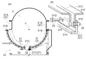
続いて、図8に示すように、後側における左右二つの網体31のうち左側の網体31が、扱室2の左側部(開口部10)から差し込まれる。そして、左側の網体31における下フランジ部31Cが、右側の網体31における下フランジ部31Cに重ね合わせされた状態で、右側の網体31における下フランジ部31Cと共に第二ボルト33で中央部フレーム21Cに固定される。第二ボルト33は、左側の網体31における下フランジ部31Cの第二ボルト孔31Fと、右側の網体31における下フランジ部31Cの第二ボルト孔31Fと、に挿通される
このとき、左側の網体31における下フランジ部31Cに、第一ボルト32よりも大きい切欠部31Hが形成されているため、左側の網体31における下フランジ部31Cを、右側の網体31における下フランジ部31Cに重ね合わせても、左側の網体31における下フランジ部31Cが、第一ボルト32と干渉することがない。
最後に、図9に示すように、左側の網体31における上フランジ部31Bが、第三ボルト34で左側部フレーム21Aに固定される。具体的には、左側の網体31における上フランジ部31Bが、左側部フレーム21Aの下面に宛がわれた状態で、第三ボルト34で左側部フレーム21Aに固定される。第三ボルト34は、左側の網体31における上フランジ部31Bの第三ボルト孔31Gに挿通される。
つまり、左側の網体31において、下フランジ部31Cの二つの固定箇所(第二ボルト孔31F)と、上フランジ部31Bの二つの固定箇所(二つの第三ボルト孔31G)とは、扱胴1の軸心Y方向における異なる位置に配置されている(図3参照)。また、右側の網体31と左側の網体31とが扱室フレーム21に固定された状態において、左側の網体31における下フランジ部31Cの第二ボルト33による二つの固定箇所(二つの第二ボルト孔31F)は、扱胴1の軸心Y方向において、右側の網体31における下フランジ部31Cの第一ボルト32による一つの固定箇所(一つの第一ボルト孔31E)を両側から挟むように配置されている。
ここで、右側の網体31を、上フランジ部31B及び下フランジ部31Cのうちプレート31Jが重ね合わせられている方の上フランジ部31Bが、正しくは、差込方向奥側の端部(右端部)となる姿勢で差し込むべきところ、誤って、差込方向手前側の端部(左端部)となる姿勢で差し込んでしまうことが考えられる。この点、右側の網体31を誤った姿勢で差し込んだ場合でも、右側の網体31における上フランジ部31Bの第一ボルト孔31Eに、第一ボルト32が挿通されることにより、右側の網体31における上フランジ部31Bが、第一ボルト32で中央部フレーム21Cに固定されてしまう。
しかし、右側の網体31を誤った姿勢で差し込んだ場合、左側の網体31における下フランジ部31Cを、右側の網体31における上フランジ部31Bに重ね合わせた状態で、右側の網体31における上フランジ部31Bと共に第二ボルト33で中央部フレーム21Cに固定しようとしても、右側の網体31における上フランジ部31Bの第二ボルト孔31Fは、プレート31Jで塞がれているため、第二ボルト33を第二ボルト孔31Fに挿通することができない。したがって、この時点で、右側の網体31を誤った姿勢で差し込んだことに気付くことになる。すなわち、右側の網体31が誤った姿勢で扱室フレーム21に固定されるのを確実に防止することができる。
また、左側の網体31を、上フランジ部31B及び下フランジ部31Cのうちプレート31Jが重ね合わせられている方の上フランジ部31Bが、正しくは、差込方向手前側の端部(左端部)となる姿勢で差し込むべきところ、誤って、差込方向奥側の端部(右端部)となる姿勢で差し込んでしまうことが考えられる。
しかし、左側に網体31を誤った姿勢で差し込んだ場合、左側の網体31における上フランジ部31Bを、右側の網体31における下フランジ部31Cに重ね合わせた状態で、右側の網体31における下フランジ部31Cと共に第二ボルト33で中央部フレーム21Cに固定しようとしても、左側の網体31における上フランジ部31Bの第二ボルト孔31Fは、プレート31Jで塞がれているため、第二ボルト33を第二ボルト孔31Fに挿通することができない。したがって、この時点で、左側の網体31を誤った姿勢で差し込んだことに気付くことになる。すなわち、左側の網体31が誤った姿勢で扱室フレーム21に固定されるのを確実に防止することができる。
なお、ここでは、四つの網体31のうち後側における左右二つの網体31を例として、網体31の固定方法について説明したが、前側における左右二つの網体31の固定方法も、後側における左右二つの網体31の固定方法と同様の手順である。
次に、プレート31Jについて、図4及び図6により説明する。
図4及び図6に示すように、プレート31Jは、略矩形状の板状部材である。プレート31Jは、長手方向が前後方向となり、短手方向が左右方向となる姿勢で、上フランジ部31Bの下面に重ね合わせられている。プレート31Jには、ボルト孔31Ja、第一切欠溝31Jb及び第二切欠溝31Jcが形成されている。
ボルト孔31Jaは、第三ボルト34を挿通可能なものである。第一切欠溝31Jb及び第二切欠溝31Jcは、プレート31Jにおける一の長辺(一対の長辺のうちの機体内側の長辺)から短手方向(機体外側方向)に沿って切欠き形成されている。ボルト孔31Jaの中心と第一切欠溝31Jbの前後中心との距離D1と、ボルト孔31Jaの中心と第二切欠溝31Jcの前後中心との距離D2と、は互いに異なる距離に設定されている。具体的には、距離D1の方が距離D2よりも大きく設定されている。
ここで、網体31において、上フランジ部31Bにおける二つの第三ボルト孔31G、及び支柱31Ab・31Adについて説明する。なお、ここでは、例として、左右二つの網体31のうち左側の網体31について説明するが、他の網体31についてもこれと同様である。
図4に示すように、網体31において、前後方向の中心線(網体31の前端部P1と後端部P2との中心線)を中心線Cとすると、上フランジ部31Bにおける二つの第三ボルト孔31Gのうち、前側の第三ボルト孔31Gと後側の第三ボルト孔31Gとは、中心線Cに対して前後対称な位置に配置されている。つまり、前側の第三ボルト孔31Gの中心と中心線Cとの距離と、後側の第三ボルト孔31Gの中心と中心線Cとの距離とは、互いに等しい距離D3に設定されている。
また、支柱31Abと支柱31Adとは、中心線Cに対して前後非対称な位置に配置されている。つまり、支柱31Abの前後中心と中心線Cとの距離D4と、支柱31Adの前後中心と中心線Cとの距離D5とは、互いに異なる距離に設定されている。具体的には、距離D4の方が距離D5よりも大きく設定されている。
また、前側の第三ボルト孔31Gの中心と支柱31Abの前後中心との距離は、距離D2に設定されている。つまり、プレート31Jにおけるボルト孔31Jaの中心と第二切欠溝31Jcの前後中心との距離D2は、前側の第三ボルト孔31Gの中心と支柱31Abの前後中心との距離D2と同一に設定されている。
また、後側の第三ボルト孔31Gの中心と支柱31Adの前後中心との距離は、距離D1に設定されている。つまり、プレート31Jにおけるボルト孔31Jaの中心と第一切欠溝31Jbの前後中心との距離D1は、後側の第三ボルト孔31Gの中心と支柱31Adの前後中心との距離D1と同一に設定されている。
このように、網体31において、前側の第三ボルト孔31Gと後側の第三ボルト孔31Gとが、中心線Cに対して前後対称な位置に配置されている。したがって、前後二つの第三ボルト孔31Gに挿通される第三ボルト34によって、網体31を前後バランス良く固定することができる。
また、網体31において、支柱31Abと支柱31Adとが中心線Cに対して前後非対称な位置に配置されている場合でも、上フランジ部31Bのうち前側部分と後側部分とで夫々専用のプレートを用意する必要がない。つまり、プレート31Jを上フランジ部31Bのうち前側部分に用いるときは、第二切欠溝31Jcに支柱31Abを入り込ませることにより、プレート31Jと支柱31Abとが干渉しない。一方、プレート31Jを上フランジ部31Bのうち後側部分に用いるときは、第一切欠溝31Jbに支柱31Adを入り込ませることにより、プレート31Jと支柱31Adとが干渉しない。これにより、上フランジ部31Bのうち前側部分と後側部分とで夫々専用のプレートを用意する必要がないので、プレート31Jの兼用化によるコストダウンが可能になる。
(1)上記実施形態では、脱穀装置が普通型コンバインに搭載された形態を想定しているが、脱穀装置が自脱型コンバインに搭載された形態でもよい。
(2)上記実施形態において、網体31の「差込方向」は、左右方向であるが、網体31の「差込方向」は、前後方向でもよい。
(3)上記実施形態において、受網3は、扱胴1の周方向に沿って二分割されているが、受網3は、扱胴1の周方向に沿って三分割以上されていてもよい。この場合、差込方向に隣り合う二つの網体31の間において、上述の構成(第一ボルト32及び第二ボルト33による固定)を採用することができる。
(4)上記実施形態において、受網3は、扱胴1の軸心Y方向に沿って二分割されているが、受網3は、受網3は、扱胴1の軸心Y方向に沿って三分割以上されていても、扱胴1の軸心Y方向に沿って分割されていなくてもよい。
(5)上記実施形態において、受網3は、四つの網体31を有しているが、受網3は、二つ若しくは三つ又は五つ以上の網体31を有していてもよい。
(6)上記実施形態において、網体31における上フランジ部31Bには、プレート31Jが重ね合わせられているが、図10に示すように、上フランジ部31Bにおける遊端側の端部が、固定部31Iに対して屈曲するように形成されていてもよい。つまり、上フランジ部31Bにおける遊端側の端部が、略L字形状に形成されていてもよい。
(7)上記実施形態において、第二ボルト33は、左側の網体31における下フランジ部31Cと、右側の網体31における下フランジ部31Cとを、中央部フレーム21Cに共締め固定しているが、第二ボルト33は、左側の網体31における下フランジ部31Cと、右側の網体31における下フランジ部31Cとを、中央部フレーム21Cに共締め固定しない(各別に中央部フレーム21Cに固定する)ものでもよい。
(8)上記実施形態において、「凹部」は、切欠部31Hで構成されているが、「凹部」は、第一ボルト32よりも大きい窪み若しくは孔で構成されていてもよい。
(9)上記実施形態において、複数の網体31は、互いに兼用可能に構成されているが、複数の網体31は、互いに兼用可能に構成されていなくてもよい。
(10)上記実施形態において、網体31における第一ボルト32による固定箇所、つまり、第一ボルト孔31Eは、一つであるが、第一ボルト孔31Eは、二つ以上でもよい。
(11)上記実施形態において、網体31における第二ボルト33による固定箇所、つまり、第二ボルト孔31Fは、二つであるが、第二ボルト孔31Fは、一つでも三つ以上でもよい。
(12)上記実施形態において、網体31における第三ボルト34による固定箇所、つまり、第三ボルト孔31Gは、二つであるが、第三ボルト孔31Gは、一つでも三つ以上でもよい。
(14)上記実施形態において、網体31における上フランジ部31Bにプレート31Jが重ね合わせられることにより、固定部31Iが形成されているが、固定部31Iを上フランジ部31Bと一体的に形成してもよい。
本発明の第二実施形態について、以下に説明する。
図12に示すように、扱室2の前下端部には、刈取穀稈が搬入される脱穀入口121が形成されている。刈取穀稈は、フィーダ8(図11参照)で脱穀入口121に搬入される。脱穀入口121には、脱穀入口プレート22が取り付けられている。脱穀入口プレート22における右側壁22aは、フィーダ8の出口から扱胴1の径に徐々に(平滑に)広がる形状に形成されている。これにより、作物が円滑に流れる(図12に示す作物の流れA参照)ため、脱穀入口プレート22(右側壁22a)の摩耗防止及び扱胴ロック(刈取穀稈の詰まり)の低減を図ることができる。
図13及び図14に示すように、扱室2の左側部には、開閉可能な脱穀開閉カバー9で覆われた開口部10が形成されている。脱穀開閉カバー9の後端部は、揺動軸91を介して、上下向きの軸心Z周りに揺動可能に支持されている。脱穀開閉カバー9の内側における前部には、外側下がりに傾斜する傾斜部92が設けられている。傾斜部92の外側端部の高さは、脱穀開閉カバー9が閉じられた状態において、開口部10の下縁部10aの高さと一致又は略一致するように設定されている。
ここで、脱穀開閉カバー9が自重で前下がりに傾くと、脱穀開閉カバー9が開口部10に対して位置ずれするため、脱穀開閉カバー9を閉じ難いことがあった。しかし、本実施形態によれば、脱穀開閉カバー9が自重で前下がりに傾いたとしても、脱穀開閉カバー9を閉じるのに連動して、傾斜部92が開口部10の下縁部10aに徐々に乗り上げることにより、脱穀開閉カバー9が前上がりに移動する。これにより、脱穀開閉カバー9が開口部10に位置決めされるため、脱穀開閉カバー9を閉じ難くなることがない。
図13に示すように、扱胴1の上部は、脱穀天板23で着脱可能に覆われている。脱穀天板23の左右両端部には、取付部23aが形成されている。取付部23aは、脱穀装置の側部を形成する側板25に、六本のボルト26で固定されている(図15参照)。具体的には、取付部23aにおいて、六本のボルト26のうち最後端のボルト26で固定される部分には、補強用のL板27が溶接されている。当該部分は、L板27が溶接された状態で、ボルト26で側板25に固定されている。また、取付部23aにおいて、六本のボルト26のうち最後端のボルト26を除く五本のボルト26で固定される部分には、補強用の平板28が溶接されている。当該部分は、平板28が溶接された状態で、ボルト26で側板25に固定されている。これにより、脱穀負荷が高い状態においては、脱穀天板23に対して上向きの力が作用するところ、L板27及び平板28で補強された状態で、取付部23aがボルト26で側板25に固定されることにより、取付部23aの耐久性を向上させることができる。
次に、扱胴1について、図16及び図17により説明する。
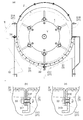
図16及び図17に示すように、扱胴1は、扱胴軸11と、前支持板12(「第一支持板」に相当)と、後支持板13(「第二支持板」に相当)と、複数の丸パイプ14(「棒状部材」に相当)と、複数の扱歯15と、仕切板16と、を備えている。
扱胴軸11は、扱室2の前壁と扱室2の後壁とに亘って架設されている。扱胴軸11の前端部は、扱室2の前壁に回転可能に支持され、扱胴軸11の後端部は、扱室2の後壁に回転可能に支持されている。扱胴軸11において、前支持板12の前面側には、刈取穀稈を脱穀入口121に送り込むためのスクリュー17が設けられている。
前支持板12は、扱胴軸11の前端部側に設けられている。前支持板12は、真円形状又は略円形状に形成されている。前支持板12の径は、丸パイプ14の断面における最も扱胴軸11に近い部分の回転軌跡Lよりも大きい。なお、丸パイプ14の断面とは、丸パイプ14の軸心方向に直交する方向の断面を意味している(以下同様)。また、前支持板12には、丸パイプ14の前端部が支持されている。具体的には、前支持板12には、丸パイプ14の前端部が前支ステー14aを介して支持されている。
前支ステー14aは、丸パイプ14の前端部に溶接その他の固定方法により固定されている。前支ステー14aは、前支持板12に二本のボルト18で固定されている。
後支持板13は、扱胴軸11の後端部側に設けられている。後支持板13は、真円形状又は略円形状に形成されている。後支持板13の径は、丸パイプ14の断面における最も扱胴軸11に近い部分の回転軌跡Lよりも大きい。後支持板13には、丸パイプ14の後端部が支持されている。具体的には、後支持板13には、丸パイプ14の後端部が後支持ステー14bを介して支持されている。
後支持ステー14bは、丸パイプ14の後端部に溶接その他の固定方法により固定されている。後支持ステー14bは、後支持板13に二本のボルト18で固定されている。
複数の丸パイプ14は、扱胴軸11を中心とする円周上に配置されている。本実施形態では、複数の丸パイプ14は、六本とされている。具体的には、六本の丸パイプ14は、扱胴軸11を中心とする円周上に等角度間隔で配置されている。丸パイプ14は、仕切板16の外周から径外方向に離間した状態で、仕切板16に支持されている。つまり、丸パイプ14は、仕切板16の外周と丸パイプ14との間に隙間Gが形成された状態で、中間支持ステー14cを介して仕切板16に支持されている。
中間支持ステー14cは、嵌合凹部が形成された平板状の部材である。嵌合凹部は、丸パイプ14の外周半部と嵌合する略半円形状に形成されている。中間支持ステー14cは、嵌合凹部に丸パイプ14が嵌合された状態で、丸パイプ14に溶接その他の固定方法により固定されている。中間支持ステー14cは、仕切板16に一本のボルト18で固定されている。具体的には、中間支持ステー14cは、仕切板16の前面に当て付けられた状態で、仕切板16の後方からボルト18で固定されている。
六本の丸パイプ14の夫々には、複数の扱歯15が設けられている。本実施形態では、複数の扱歯15の間隔は、六本の丸パイプ14のうち隣り合う丸パイプ14同士で異なっている。具体的には、六本の丸パイプ14のうち三本の丸パイプ14には、扱歯15が等間隔D6で設けられ、残る三本の丸パイプ14には、扱歯15が間隔D6よりも小さい等間隔D7で設けられている。扱胴軸11の方向において、間隔D6で配置された扱歯15同士の間に、間隔D7で配置された扱歯15が二本存在している。
仕切板16は、扱胴軸11において前支持板12と後支持板13との間に設けられている。具体的には、仕切板16は、扱胴軸11において前支持板12と後支持板13との真ん中又は略真ん中に設けられている。また、仕切板16は、丸パイプ14の前端部と後端部との間を支持している。具体的には、仕切板16は、丸パイプ14における軸心方向の中央部又は略中央部を支持している。
仕切板16は、略円形状に形成されている。具体的には、仕切板16は、真円形状に形成されている。仕切板16の径は、丸パイプ14の断面における最も扱胴軸11に近い部分の回転軌跡Lよりも小さい。仕切板16の径は、前支持板12の径よりも小さく、かつ、後支持板13の径よりも小さい。
扱胴軸11の軸心Y方向において、仕切板16は、複数の扱歯15のうち隣り合う扱歯15同士の間に配置されている。つまり、扱胴軸11の軸心Y方向において、仕切板16は、間隔D1で配置された扱歯15同士の間であり、かつ、間隔D2で配置された扱歯15同士の間に配置されている。
以上のような構成により、仕切板16の小型化が可能となる。したがって、仕切板16の小型化により、扱胴1の軽量化が可能となる。そうすると、このような扱胴1を備えたコンバインにおいては、脱穀負荷が減少するため、燃費が向上する。また、仕切板16の小型化により、仕切板16を構成する材料が減少するため、コストダウンが可能となる。
〔第二実施形態の別実施形態〕
(1)上記実施形態では、普通型コンバインに搭載された脱穀装置に、扱胴1が備えられた形態を想定しているが、自脱型コンバインに搭載された脱穀装置に、扱胴1が備えられた形態でもよい。
(2)上記実施形態において、丸パイプ14は、六本であるが、丸パイプ14は、五本以下でも、七本以上でもよい。
(3)上記実施形態において、仕切板16は、真円形状であるが、仕切板16は、径方向に多少の凹凸が形成された略円形状でもよい。
(4)上記実施形態において、丸パイプ14の断面は、真円形状であるが、丸パイプ14の断面は、略円形状でもよい。また、「棒状部材」は、丸パイプ14であるが、「棒状部材」は、角パイプでもよい。
(5)上記実施形態において、複数の扱歯15の間隔は、六本の丸パイプ14のうち隣り合う丸パイプ14同士で異なっているが、複数の扱歯15の間隔は、六本の丸パイプ14において同一でもよい。
2 扱室
3 受網
11 扱胴軸
12 前支持板(第一支持板)
13 後支持板(第二支持板)
14 丸パイプ(棒状部材)
15 扱歯
16 仕切板
21 扱室フレーム
21A 左側部フレーム(側部フレーム)
31 網体
31B 上フランジ部(フランジ部)
31C 下フランジ部(フランジ部)
31F 第二ボルト孔(第二挿通孔)
31G 第三ボルト孔(第三挿通孔)
31H 切欠部(凹部)
31I 固定部
31J プレート
32 第一ボルト(第一固定具)
33 第二ボルト(第二固定具)
34 第三ボルト(第三固定具)
L 回転軌跡
Y 軸心
Claims (17)
- [規則91に基づく訂正 12.03.2014]
扱胴が設けられる扱室と、
前記扱室を形成する扱室フレームと、
前記扱胴の下方に設けられる受網と、を備え、
前記受網は、前記扱胴の周方向に沿って分割され、前記扱室の一側部から順次差し込まれる複数の網体を有し、
複数の前記網体の夫々は、各別に前記扱室フレームに固定されている脱穀装置。 - 複数の前記網体のうち差込方向最奥側の網体において、その差込方向手前側の端部が前記扱室フレームに固定されている請求項1に記載の脱穀装置。
- 複数の前記網体のうち差込方向に隣り合う二つの網体において、差込方向奥側の網体における差込方向手前側の端部は、第一固定具で前記扱室フレームに固定され、差込方向手前側の網体における差込方向奥側の端部は、前記差込方向奥側の網体における差込方向手前側の端部に重ね合わせされた状態で、前記差込方向奥側の網体における差込方向手前側の端部と共に第二固定具で前記扱室フレームに固定され、
前記差込方向手前側の網体における差込方向奥側の端部に、前記第一固定具よりも大きい凹部が形成されている請求項1又は2に記載の脱穀装置。 - 前記差込方向手前側の網体における差込方向奥側の端部は、前記第二固定具によって複数箇所で前記扱室フレームに固定され、
前記差込方向奥側の網体と前記差込方向手前側の網体とが前記扱室フレームに固定された状態において、前記差込方向手前側の網体における差込方向奥側の端部の前記第二固定具による複数の固定箇所は、前記扱胴の軸心方向において、前記差込方向奥側の網体における差込方向手前側の端部の前記第一固定具による固定箇所を両側から挟むように配置されている請求項3に記載の脱穀装置。 - 複数の前記網体は、互いに兼用可能に構成されている請求項1から4までの何れか一項に記載の脱穀装置。
- 複数の前記網体は、同一部材で構成され、
複数の前記網体の夫々において、差込方向手前側の端部の固定箇所と、差込方向奥側の端部の固定箇所とは、前記扱胴の軸心方向における異なる位置に配置されている請求項5に記載の脱穀装置。 - 前記扱室フレームは、前記扱室の一側部で前後方向に延びる側部フレームを有し、
複数の前記網体のうち差込方向最手前側の網体における差込方向手前側の端部に、フランジ部が形成され、
前記フランジ部に、前記側部フレームに固定される部分としての固定部が形成され、
前記フランジ部のうち前記固定部の部分の厚さは、前記フランジ部のうち前記固定部以外の部分の厚さよりも厚い請求項1から6までの何れか一項に記載の脱穀装置。 - 前記フランジ部にプレートが重ね合わせられることにより、前記固定部が形成されている請求項7に記載の脱穀装置。
- 複数の前記網体は、互いに兼用可能に構成され、
複数の前記網体の夫々における差込方向の両端部に、前記フランジ部が形成され、
複数の前記網体のうち差込方向に隣り合う二つの網体において、差込方向手前側の網体における差込方向奥側の端部は、差込方向奥側の網体における差込方向手前側の端部に重ね合わせされた状態で、前記差込方向奥側の網体における差込方向手前側の端部と共に第二固定具で前記扱室フレームに固定され、
前記固定部は、第三固定具で前記側部フレームに固定され、
複数の前記網体の夫々における両フランジ部に、前記第二固定具を挿通可能な第二挿通孔と、前記第三固定具を挿通可能な第三挿通孔と、が形成され、
複数の前記網体の夫々における両フランジ部のうち何れか一方のフランジ部のみに、前記固定部が形成され、
前記プレートは、複数の前記網体の夫々における両フランジ部のうち何れか一方のフランジ部において、前記第二固定具を挿通しない前記第二挿通孔を塞いでいる請求項8に記載の脱穀装置。 - 前記扱室フレームは、前記扱室の一側部で前後方向に延びる側部フレームを有し、
複数の前記網体のうち差込方向最手前側の網体における差込方向手前側の端部に、フランジ部が形成され、
前記フランジ部に、前記側部フレームに固定される部分としての固定部が形成され、
前記フランジ部における遊端側の端部は、前記固定部に対して屈曲するように形成されている請求項1から4までの何れか一項に記載の脱穀装置。 - 扱胴を備えた脱穀装置であって、
前記扱胴は、
扱胴軸と、
前記扱胴軸の一端部側に設けられる第一支持板と、
前記扱胴軸の他端部側に設けられる第二支持板と、
一端部が前記第一支持板に支持され、かつ、他端部が前記第二支持板に支持され、前記扱胴軸を中心とする円周上に配置される複数の棒状部材と、
複数の前記棒状部材の夫々に複数ずつ設けられる複数の扱歯と、
前記扱胴軸において前記第一支持板と前記第二支持板との間に設けられ、複数の前記棒状部材の一端部と他端部との間を支持する略円形状の仕切板と、を備え、
前記仕切板の径は、前記棒状部材の断面における最も前記扱胴軸に近い部分の回転軌跡よりも小さい脱穀装置。 -
前記棒状部材は、前記仕切板の外周から径外方向に離間した状態で、前記仕切板に支持されている請求項11に記載の脱穀装置。 -
前記仕切板は、真円形状である請求項11又は12に記載の脱穀装置。 -
前記扱胴軸の軸心方向において、前記仕切板は、複数の前記扱歯のうち隣り合う前記扱歯同士の間に配置されている請求項11から13までの何れか一項に記載の脱穀装置。 -
複数の前記扱歯の間隔は、複数の前記棒状部材のうち隣り合う前記棒状部材同士で異なる請求項14に記載の脱穀装置。 -
前記第一支持板は、略円形状であり、
前記仕切板の径は、前記第一支持板の径よりも小さい請求項11から15までの何れか一項に記載の脱穀装置。 -
前記第二支持板は、略円形状であり、
前記仕切板の径は、前記第二支持板の径よりも小さい請求項11から16までの何れか一項に記載の脱穀装置。
Priority Applications (3)
| Application Number | Priority Date | Filing Date | Title |
|---|---|---|---|
| CN201480008565.2A CN104981146B (zh) | 2013-02-22 | 2014-01-30 | 脱粒装置 |
| PH12015501841A PH12015501841B1 (en) | 2013-02-22 | 2015-08-20 | Threshing apparatus |
| PH12017501715A PH12017501715B1 (en) | 2013-02-22 | 2017-09-19 | Threshing apparatus |
Applications Claiming Priority (6)
| Application Number | Priority Date | Filing Date | Title |
|---|---|---|---|
| JP2013-033727 | 2013-02-22 | ||
| JP2013-033725 | 2013-02-22 | ||
| JP2013033727 | 2013-02-22 | ||
| JP2013033725A JP6327788B2 (ja) | 2013-02-22 | 2013-02-22 | 扱胴 |
| JP2013148676A JP6129002B2 (ja) | 2013-02-22 | 2013-07-17 | 脱穀装置 |
| JP2013-148676 | 2013-07-17 |
Publications (1)
| Publication Number | Publication Date |
|---|---|
| WO2014129284A1 true WO2014129284A1 (ja) | 2014-08-28 |
Family
ID=51391080
Family Applications (1)
| Application Number | Title | Priority Date | Filing Date |
|---|---|---|---|
| PCT/JP2014/052121 Ceased WO2014129284A1 (ja) | 2013-02-22 | 2014-01-30 | 脱穀装置 |
Country Status (1)
| Country | Link |
|---|---|
| WO (1) | WO2014129284A1 (ja) |
Citations (7)
| Publication number | Priority date | Publication date | Assignee | Title |
|---|---|---|---|---|
| JPS62102333U (ja) * | 1985-12-17 | 1987-06-30 | ||
| JP2001061335A (ja) * | 1999-08-25 | 2001-03-13 | Kubota Corp | 自脱型コンバインの脱穀装置 |
| JP2006311820A (ja) * | 2005-05-09 | 2006-11-16 | Kubota Corp | 脱穀装置の受網脱着構造 |
| JP2009207360A (ja) * | 2008-02-29 | 2009-09-17 | Kubota Corp | 扱胴 |
| JP2010233475A (ja) * | 2009-03-30 | 2010-10-21 | Kubota Corp | コンバインの脱穀装置 |
| JP2012205565A (ja) * | 2011-03-30 | 2012-10-25 | Kubota Corp | 脱穀装置 |
| JP2013132271A (ja) * | 2011-12-27 | 2013-07-08 | Kubota Corp | 普通型コンバインの脱穀部 |
-
2014
- 2014-01-30 WO PCT/JP2014/052121 patent/WO2014129284A1/ja not_active Ceased
Patent Citations (7)
| Publication number | Priority date | Publication date | Assignee | Title |
|---|---|---|---|---|
| JPS62102333U (ja) * | 1985-12-17 | 1987-06-30 | ||
| JP2001061335A (ja) * | 1999-08-25 | 2001-03-13 | Kubota Corp | 自脱型コンバインの脱穀装置 |
| JP2006311820A (ja) * | 2005-05-09 | 2006-11-16 | Kubota Corp | 脱穀装置の受網脱着構造 |
| JP2009207360A (ja) * | 2008-02-29 | 2009-09-17 | Kubota Corp | 扱胴 |
| JP2010233475A (ja) * | 2009-03-30 | 2010-10-21 | Kubota Corp | コンバインの脱穀装置 |
| JP2012205565A (ja) * | 2011-03-30 | 2012-10-25 | Kubota Corp | 脱穀装置 |
| JP2013132271A (ja) * | 2011-12-27 | 2013-07-08 | Kubota Corp | 普通型コンバインの脱穀部 |
Similar Documents
| Publication | Publication Date | Title |
|---|---|---|
| JP7209236B1 (ja) | 脱穀装置の扱胴 | |
| JP5437117B2 (ja) | 脱穀装置 | |
| JP2023026613A (ja) | コンバイン | |
| JP2019080508A (ja) | 脱穀用扱胴 | |
| JP2023026613A5 (ja) | ||
| JP2019208393A (ja) | 扱胴 | |
| JP6995132B2 (ja) | 扱胴 | |
| CN104981146B (zh) | 脱粒装置 | |
| JP5739709B2 (ja) | 脱穀装置 | |
| JP2012231703A (ja) | コンバインの扱胴 | |
| EP3804498A1 (en) | Threshing cylinder | |
| CN105993413B (zh) | 脱粒装置的处理筒 | |
| JP6327788B2 (ja) | 扱胴 | |
| JP6129002B2 (ja) | 脱穀装置 | |
| JP6444724B2 (ja) | 脱穀装置の格子網 | |
| JP7292021B2 (ja) | 脱穀装置 | |
| JP5584644B2 (ja) | 脱穀装置用の扱胴 | |
| JP6335514B2 (ja) | 脱穀装置 | |
| JP2009240163A (ja) | 脱穀装置 | |
| JP2021100387A (ja) | 脱穀装置の扱胴 | |
| JP7288621B1 (ja) | 脱穀装置の扱胴 | |
| JP2016116496A (ja) | 脱穀装置の格子網 | |
| JP2019208392A (ja) | 扱胴 | |
| JP2006174710A (ja) | コンバイン | |
| JP2019004851A (ja) | 脱穀装置及び扱胴の製造方法 |
Legal Events
| Date | Code | Title | Description |
|---|---|---|---|
| 121 | Ep: the epo has been informed by wipo that ep was designated in this application |
Ref document number: 14753788 Country of ref document: EP Kind code of ref document: A1 |
|
| NENP | Non-entry into the national phase |
Ref country code: DE |
|
| WWE | Wipo information: entry into national phase |
Ref document number: IDP00201505330 Country of ref document: ID |
|
| 122 | Ep: pct application non-entry in european phase |
Ref document number: 14753788 Country of ref document: EP Kind code of ref document: A1 |
|
| WWE | Wipo information: entry into national phase |
Ref document number: 12017501715 Country of ref document: PH |