WO2014129244A1 - ボイラ運転方法およびボイラ - Google Patents
ボイラ運転方法およびボイラ Download PDFInfo
- Publication number
- WO2014129244A1 WO2014129244A1 PCT/JP2014/050970 JP2014050970W WO2014129244A1 WO 2014129244 A1 WO2014129244 A1 WO 2014129244A1 JP 2014050970 W JP2014050970 W JP 2014050970W WO 2014129244 A1 WO2014129244 A1 WO 2014129244A1
- Authority
- WO
- WIPO (PCT)
- Prior art keywords
- water
- storage
- boiler
- range
- supply system
- Prior art date
- Legal status (The legal status is an assumption and is not a legal conclusion. Google has not performed a legal analysis and makes no representation as to the accuracy of the status listed.)
- Ceased
Links
Images


Classifications
-
- F—MECHANICAL ENGINEERING; LIGHTING; HEATING; WEAPONS; BLASTING
- F01—MACHINES OR ENGINES IN GENERAL; ENGINE PLANTS IN GENERAL; STEAM ENGINES
- F01K—STEAM ENGINE PLANTS; STEAM ACCUMULATORS; ENGINE PLANTS NOT OTHERWISE PROVIDED FOR; ENGINES USING SPECIAL WORKING FLUIDS OR CYCLES
- F01K25/00—Plants or engines characterised by use of special working fluids, not otherwise provided for; Plants operating in closed cycles and not otherwise provided for
- F01K25/06—Plants or engines characterised by use of special working fluids, not otherwise provided for; Plants operating in closed cycles and not otherwise provided for using mixtures of different fluids
-
- F—MECHANICAL ENGINEERING; LIGHTING; HEATING; WEAPONS; BLASTING
- F22—STEAM GENERATION
- F22B—METHODS OF STEAM GENERATION; STEAM BOILERS
- F22B1/00—Methods of steam generation characterised by form of heating method
- F22B1/02—Methods of steam generation characterised by form of heating method by exploitation of the heat content of hot heat carriers
- F22B1/18—Methods of steam generation characterised by form of heating method by exploitation of the heat content of hot heat carriers the heat carrier being a hot gas, e.g. waste gas such as exhaust gas of internal-combustion engines
- F22B1/1807—Methods of steam generation characterised by form of heating method by exploitation of the heat content of hot heat carriers the heat carrier being a hot gas, e.g. waste gas such as exhaust gas of internal-combustion engines using the exhaust gases of combustion engines
- F22B1/1815—Methods of steam generation characterised by form of heating method by exploitation of the heat content of hot heat carriers the heat carrier being a hot gas, e.g. waste gas such as exhaust gas of internal-combustion engines using the exhaust gases of combustion engines using the exhaust gases of gas-turbines
-
- F—MECHANICAL ENGINEERING; LIGHTING; HEATING; WEAPONS; BLASTING
- F01—MACHINES OR ENGINES IN GENERAL; ENGINE PLANTS IN GENERAL; STEAM ENGINES
- F01K—STEAM ENGINE PLANTS; STEAM ACCUMULATORS; ENGINE PLANTS NOT OTHERWISE PROVIDED FOR; ENGINES USING SPECIAL WORKING FLUIDS OR CYCLES
- F01K23/00—Plants characterised by more than one engine delivering power external to the plant, the engines being driven by different fluids
- F01K23/02—Plants characterised by more than one engine delivering power external to the plant, the engines being driven by different fluids the engine cycles being thermally coupled
- F01K23/06—Plants characterised by more than one engine delivering power external to the plant, the engines being driven by different fluids the engine cycles being thermally coupled combustion heat from one cycle heating the fluid in another cycle
- F01K23/10—Plants characterised by more than one engine delivering power external to the plant, the engines being driven by different fluids the engine cycles being thermally coupled combustion heat from one cycle heating the fluid in another cycle with exhaust fluid of one cycle heating the fluid in another cycle
-
- F—MECHANICAL ENGINEERING; LIGHTING; HEATING; WEAPONS; BLASTING
- F22—STEAM GENERATION
- F22B—METHODS OF STEAM GENERATION; STEAM BOILERS
- F22B35/00—Control systems for steam boilers
- F22B35/007—Control systems for waste heat boilers
-
- F—MECHANICAL ENGINEERING; LIGHTING; HEATING; WEAPONS; BLASTING
- F22—STEAM GENERATION
- F22D—PREHEATING, OR ACCUMULATING PREHEATED, FEED-WATER FOR STEAM GENERATION; FEED-WATER SUPPLY FOR STEAM GENERATION; CONTROLLING WATER LEVEL FOR STEAM GENERATION; AUXILIARY DEVICES FOR PROMOTING WATER CIRCULATION WITHIN STEAM BOILERS
- F22D1/00—Feed-water heaters, i.e. economisers or like preheaters
- F22D1/16—Feed-water heaters, i.e. economisers or like preheaters with water tubes arranged otherwise than in the boiler furnace, fire tubes, or flue ways
- F22D1/18—Feed-water heaters, i.e. economisers or like preheaters with water tubes arranged otherwise than in the boiler furnace, fire tubes, or flue ways and heated indirectly
-
- Y—GENERAL TAGGING OF NEW TECHNOLOGICAL DEVELOPMENTS; GENERAL TAGGING OF CROSS-SECTIONAL TECHNOLOGIES SPANNING OVER SEVERAL SECTIONS OF THE IPC; TECHNICAL SUBJECTS COVERED BY FORMER USPC CROSS-REFERENCE ART COLLECTIONS [XRACs] AND DIGESTS
- Y02—TECHNOLOGIES OR APPLICATIONS FOR MITIGATION OR ADAPTATION AGAINST CLIMATE CHANGE
- Y02E—REDUCTION OF GREENHOUSE GAS [GHG] EMISSIONS, RELATED TO ENERGY GENERATION, TRANSMISSION OR DISTRIBUTION
- Y02E20/00—Combustion technologies with mitigation potential
- Y02E20/16—Combined cycle power plant [CCPP], or combined cycle gas turbine [CCGT]
-
- Y—GENERAL TAGGING OF NEW TECHNOLOGICAL DEVELOPMENTS; GENERAL TAGGING OF CROSS-SECTIONAL TECHNOLOGIES SPANNING OVER SEVERAL SECTIONS OF THE IPC; TECHNICAL SUBJECTS COVERED BY FORMER USPC CROSS-REFERENCE ART COLLECTIONS [XRACs] AND DIGESTS
- Y02—TECHNOLOGIES OR APPLICATIONS FOR MITIGATION OR ADAPTATION AGAINST CLIMATE CHANGE
- Y02E—REDUCTION OF GREENHOUSE GAS [GHG] EMISSIONS, RELATED TO ENERGY GENERATION, TRANSMISSION OR DISTRIBUTION
- Y02E20/00—Combustion technologies with mitigation potential
- Y02E20/16—Combined cycle power plant [CCPP], or combined cycle gas turbine [CCGT]
- Y02E20/18—Integrated gasification combined cycle [IGCC], e.g. combined with carbon capture and storage [CCS]
Definitions
- the present invention relates to a boiler operation method and a boiler, and more particularly, to a boiler operation method and a boiler used when storing a water supply system in which can water circulates.
- Steam (steam) generated in the water supply system in which can water circulates includes boilers and steam turbine power generation facilities, gas turbines (exhaust heat recovery boiler) steam turbine combined power generation facilities, etc., but coal gasification combined power generation facilities (IGCC: Integrated coal Gasification Combined Cycle) is a facility that has many water supply systems that generate steam.
- the coal gasification combined power generation facility includes a coal gasification furnace, a gas cooler, a gas turbine facility, an exhaust heat recovery boiler, a steam turbine facility, and a generator.
- the coal gasification furnace generates combustible product gas by gasifying pulverized coal.
- the gas cooler cools the product gas.
- the gas turbine equipment generates high-temperature and high-pressure combustion gas by burning the cooled product gas, and generates rotational power.
- the exhaust heat recovery boiler recovers thermal energy from the exhaust gas of the gas turbine equipment and generates high-pressure steam.
- the steam turbine facility generates rotational power using steam.
- the generator converts rotational power generated by the gas turbine
- the gas cooler and the exhaust heat recovery boiler are provided with a water supply system through which can water circulates.
- the gas cooler cools the generated gas generated by the coal gasification furnace
- the exhaust heat recovery boiler cools the exhaust gas exhausted from the gas turbine equipment.
- the gas cooler and the exhaust heat recovery boiler circulate through the water supply system, thereby heating the can water and generating steam supplied to the steam turbine equipment.
- the operation of the coal gasification combined power generation facility is stopped due to periodic inspections, etc. and the equipment is being stored for a long period of time, if it is necessary to replace the piping of the water supply system, etc., drain the can water and respond .
- it is desired to prevent corrosion of metal components such as the inside of the piping of the water supply system when storing without draining the can water in order to restart quickly.
- An object of the present invention is to provide a boiler operation method and a boiler that can easily reduce corrosion of a water supply system through which can water flows.
- the boiler operation method according to the first aspect of the present invention is executed using a water supply system portion of the boiler.
- the boiler includes a water supply system through which heated can water flows and ammonia addition equipment for adding ammonia for adjusting pH to the can water.
- the boiler operation method according to the present invention includes measuring the pH of the can water and operating the boiler so that the can water is heated when the pH is included in the operating pH range. Controlling the ammonia addition equipment so that ammonia is added to the can water until the pH falls within the storage pH range when flowing the water through the water supply system, and when the pH is within the storage pH range. Stopping the flow of the can water to the water supply system when it is included in the storage pH range. At this time, the arbitrary pH included in the storage pH range is equal to or higher than the arbitrary pH included in the operating pH range.
- the canned water whose pH is included in the storage pH range is filled in the feed water system, so that the can water whose pH is included in the operating pH range is filled in the feed water system.
- ammonia can generally be handled more easily than hydrazine.
- such a boiler operation method can more easily prevent the water supply system from corroding as compared with filling the water supply system with canned water for storage containing hydrazine.
- the storage pH is included in the operation pH range in the restart operation of the boiler after the can water stops flowing to the water supply system.
- the can water further flows through the water supply system so that the can water is heated.
- the boiler can be easily and quickly used by using the storage can water as it is as the operation can water. Can be restarted.
- the boiler operation method refers to a table associating a plurality of storage periods with a plurality of storage pH ranges, and the storage corresponding to a power generation facility stop period in which the canned water does not flow into the water supply system And further deriving a working pH range from the plurality of storage pH ranges.
- the lower limit of the first storage pH range corresponding to the first period of the plurality of storage pH ranges corresponds to a second period longer than the first period of the plurality of storage pH ranges. Greater than the lower limit of the second storage pH range.
- an appropriate amount of ammonia can be added to the can water, and corrosion of the water supply system can be more appropriately reduced during equipment storage.
- the boiler according to the second aspect of the present invention includes a water supply system through which heated can water flows, ammonia addition equipment for adding ammonia to the can water, a pH measuring device for measuring the pH of the can water, and ammonia. And a control device for controlling the addition equipment.
- the control device controls the ammonia addition facility so that the pH is included in the operating pH range when the can water flows through the water supply system so that the can water is heated.
- the ammonia addition equipment is controlled so that the pH is included in the storage pH range before the can water stops flowing through the water supply system.
- a storage control circuit At this time, the arbitrary pH included in the storage pH range is equal to or higher than the arbitrary pH included in the operating pH range.
- the water supply system is filled with canned water whose pH is included in the storage pH range, and the water supply system is filled with canned water whose pH is included in the operating pH range.
- the corrosion of the water supply system it is possible to reduce the corrosion of the water supply system.
- ammonia can generally be handled more easily than hydrazine. For this reason, such a boiler can suppress more easily that a water supply system corrodes during apparatus storage compared with filling the water supply system with canned water for storage containing hydrazine.
- a gas cooler includes a flow path through which a product gas generated by gasifying a solid carbonaceous fuel with an oxidant and a flow path through which feed water flows (can water circulation system). Yes. At this time, the water supply system heats the can water using the heat of the generated gas.
- Such a gas cooler can more easily suppress corrosion of the water supply system during storage of equipment when the power generation equipment is stopped.
- An exhaust heat recovery boiler includes a flow path through which exhaust gas exhausted from a gas turbine and a flow path (canned water circulation system) through which feed water flows, and the water supply system uses the heat of the exhaust gas. Use to heat the can water.
- Such a waste heat recovery boiler can more easily prevent the water supply system from being corroded during storage of the equipment when the power generation facility is stopped.
- a coal gasification combined cycle power generation facility includes an exhaust heat recovery boiler according to the present invention, a gasification furnace that generates a generated gas by gasifying solid carbonaceous fuel, and the generated gas.
- a gas turbine that exhausts exhaust gas by generating power using the steam and a steam turbine that generates power using steam are provided. At this time, the steam is generated when the water supply system heats the can water using the heat of the generated gas and the heat of the exhaust gas.
- Such a coal gasification combined cycle power generation facility can more easily suppress corrosion of the water supply system during storage of equipment when the power generation facility is stopped.
- the boiler operation method and the boiler according to the present invention can easily reduce the corrosion of the water supply system during storage of equipment by filling the water supply system with can water having a pH greater than that of the can water circulating during operation. it can.
- the water supply system portion of the boiler is used for the coal gasification combined power generation facility 10 as shown in FIG.
- the coal gasification combined power generation facility 10 includes a gasification furnace 1, a gas cooler 2, a gas turbine 3, an exhaust heat recovery boiler 5, a steam turbine 6, a generator 7, and a condenser 8.
- the gasification furnace 1 generates flammable high-temperature product gas from pulverized coal obtained by crushing coal as solid carbonaceous fuel supplied from an external facility and air (or oxygen) as an oxidant.
- the gas cooler 2 generates a product gas after cooling from a high-temperature product gas generated by the gasification furnace 1.
- the gas cooler 2 generates high-temperature and high-pressure steam from the can water generated by the condenser 8 by heat exchange for cooling the high-temperature generated gas.
- the gas turbine 3 generates rotational power using the cooled product gas generated by the gas cooler 2 and exhausts high-temperature exhaust gas.
- the exhaust heat recovery boiler 5 generates high-temperature and high-pressure steam from the can water generated by the condenser 8 by heat exchange for cooling the high-temperature exhaust gas exhausted from the gas turbine 3.
- the steam turbine 6 generates rotational power using the steam generated by the gas cooler 2 and the steam generated by the exhaust heat recovery boiler 5, and exhausts the exhaust steam.
- the generator 7 generates power using the rotational power generated by the gas turbine 3 and the rotational power generated by the steam turbine 6.
- the condenser 8 generates water from the exhaust steam exhausted by the steam turbine 6 and uses it as can water.
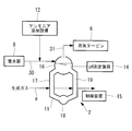
- FIG. 2 shows a water supply (circulation) system portion of the gas cooler 2.
- the gas cooler 2 includes a water supply (circulation) system 11, an ammonia addition facility 12, a pH measurement device 14, and a control device 15, and a generated gas flow path a.
- a product gas generated by the gasification furnace 1 flows through the product gas flow path a.
- the water supply system 11 includes a steam drum 16, a plurality of downcomer pipes 17, a header 18, and a plurality of heat transfer pipes 19.
- the steam drum 16 is formed of a steel-based material (hereinafter referred to as steel) and is formed in a container.
- the steam drum 16 is connected from the condenser 8 via the pipe line 30 so that the can water generated by the condenser 8 is supplied into the steam drum 16.
- the steam drum 16 is connected to the steam turbine 6 via a pipe line 31 so that steam generated inside the steam drum 16 is supplied to the steam turbine 6.
- the steam drum 16 is further connected to the plurality of downcomer pipes 17 so that the canned water stored inside the steam drum 16 is supplied to the plurality of downcomer pipes 17.
- Each of the plurality of downcomer pipes 17 is made of steel and forms a flow path through which canned water supplied from the steam drum 16 flows.
- the plurality of downcomers 17 are each connected to the header 18 so that can water is supplied to the header 18.
- the header 18 is made of steel, and is formed into a header to which canned water supplied from a plurality of downcomer pipes 17 are joined.
- the header 18 is further connected to the plurality of heat transfer tubes 19 so that the can water is supplied to the plurality of heat transfer tubes 19.
- the plurality of heat transfer tubes 19 are formed of steel, and form a flow path through which can water supplied from the header 18 flows.
- the plurality of heat transfer tubes 19 are arranged in the generated gas flow path a so as to be heated by the heat of the generated gas generated by the gasification furnace 1.
- the plurality of heat transfer tubes 19 are further connected to the steam drum 16 so that canned water supplied from the header 18 is supplied to the steam drum 16.
- the ammonia addition facility 12 is electrically connected to the control device 15 so as to transmit information, and stores an ammonia solution.
- the ammonia addition facility 12 supplies the ammonia solution to the conduit 30 so that the ammonia solution is added to the can water supplied from the condenser 8 to the steam drum 16 by being controlled by the control device 15.
- the pH measuring device 14 is electrically connected to the control device 15 so that information can be transmitted.
- the pH measuring device 14 is controlled by the control device 15 to measure the pH of the canned water stored in the steam drum 16 at predetermined time intervals or continuously.
- the control device 15 is a computer, and includes a CPU, a storage device, a memory drive, a communication device, and an interface (not shown).
- the interface outputs information generated by an external device connected to the control device 15 to the CPU, and outputs information generated by the CPU to the external device.
- the external device includes an ammonia addition facility 12 and a pH measurement device 14.
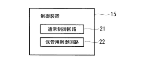
- the computer program installed in the control device 15 is formed of a plurality of computer programs for causing the control device 15 to realize a plurality of functions, as shown in FIG.
- the plurality of functions includes a normal control circuit 21 and a storage control circuit 22.
- the pH measuring device 14 measures the pH of the can water stored in the steam drum 16 at least once while the gasifier 1 and the gas cooler 2 are in operation.
- the normal control circuit 21 records the operating pH range in the storage device in advance. The set value of the operating pH range is, for example, 9.7.
- the normal control circuit 21 further controls the ammonia addition facility 12 so that the pH of the can water stored in the steam drum 16 is included in the operating pH range. That is, the normal control circuit 21 controls the ammonia addition facility 12 so that the ammonia solution is supplied to the pipe line 30 when the pH of the can water is smaller than the set value of the operating pH range.
- the normal control circuit 21 controls the ammonia addition facility 12 so that the ammonia solution is not supplied to the pipe line 30 when the pH of the can water is equal to or larger than the set value of the operating pH range.
- the storage control circuit 22 records the storage pH range in the storage device in advance.
- the lower limit of the storage pH range is equal to or larger than the set value of the operation pH range, for example, 9.7.
- the storage control circuit 22 further controls the ammonia addition facility 12 so that the pH of the can water stored in the steam drum 16 is included in the storage pH range. That is, the storage control circuit 22 sets the ammonia addition facility 12 so that the ammonia solution is supplied to the pipe line 30 when the pH of the can water stored in the steam drum 16 is smaller than the lower limit of the storage pH range. Control.
- the storage control circuit 22 controls the ammonia addition facility 12 so that the ammonia solution is not supplied to the pipe line 30 when the pH of the can water stored in the steam drum 16 is larger than the lower limit of the storage pH range.
- the exhaust heat recovery boiler 5 has a water supply system (not shown).
- the water supply system is formed in a similar manner to the water supply system 11, that is, includes a steam drum, a plurality of downcomers, a header, and a plurality of heat transfer tubes.
- the steam drum is formed from steel and is formed in a container.
- the steam drum is connected to the pipe line 30 and connected to the pipe line 31.
- the steam drum is further connected to a plurality of downcomers so that canned water stored inside the steam drum is supplied to the plurality of downcomers.
- the plurality of downcomers are each made of steel and form a flow path through which canned water supplied from the steam drum flows.
- Each of the plurality of downcomers is connected to the header so that can water is supplied to the header.
- the header is made of steel and is formed in a container that stores canned water supplied from a plurality of downcomers.
- the header is further connected to the plurality of heat transfer tubes so that the can water is supplied to the plurality of heat transfer tubes.
- the plurality of heat transfer tubes are made of steel and form a flow path through which canned water supplied from the header flows.
- the plurality of heat transfer tubes are arranged in the flow path through which the exhaust gas flows so as to be heated by the heat of the exhaust gas exhausted from the gas turbine 3.
- the plurality of heat transfer tubes are further connected to the steam drum so that can water supplied from the header is supplied to the steam drum.
- the embodiment of the boiler operation method according to the present invention is executed using the coal gasification combined power generation facility 10 and includes a normal operation, a storage operation, and a restart operation.
- the gasifier 1 is combustible by crushing and burning coal as a solid carbonaceous fuel supplied from an external facility using air (or oxygen) supplied from the external facility.
- the gas cooler 2 uses the can water generated by the condenser 8 to perform heat exchange so as to cool the high-temperature generated gas generated by the gasification furnace 1, thereby generating a product gas after cooling.
- the gas cooler 2 uses the heat of the high-temperature generated gas generated by the gasification furnace 1 to perform heat exchange so as to heat the can water, thereby generating high-temperature and high-pressure steam.
- the gas turbine 3 generates high-temperature and high-pressure exhaust gas by burning the cooled product gas generated by the gas cooler 2.
- the gas turbine 3 further generates rotational power using the kinetic energy of the exhaust gas, and exhausts the exhaust gas.
- the exhaust heat recovery boiler 5 uses the can water generated by the condenser 8 to exchange heat so as to cool the high temperature exhaust gas exhausted from the gas turbine 3, thereby generating exhaust gas after cooling.
- the exhaust heat recovery boiler 5 uses the heat of the high-temperature exhaust gas exhausted from the gas turbine 3 to perform heat exchange so as to heat the can water generated by the condenser 8, thereby generating high-temperature and high-pressure steam. Is generated.
- the steam turbine 6 generates rotational power using the kinetic energy of the high-temperature and high-pressure steam generated by the gas cooler 2 and the kinetic energy of the high-temperature and high-pressure steam generated by the exhaust heat recovery boiler 5, and generates the exhaust steam.
- the generator 7 generates power using the rotational power generated by the gas turbine 3 and the rotational power generated by the steam turbine 6.
- the condenser 8 generates water by exchanging heat so as to cool the exhaust steam exhausted by the steam turbine 6 to form canned water, and the can water is recovered from the gas cooler 2 and the exhaust heat through the pipe line 30. Supply to boiler 5.
- the pH measuring device 14 measures the pH of the can water stored in the steam drum 16 of the gas cooler 2.
- the pH measurement device 14 transmits the measured pH to the control device 15.
- the control device 15 controls the ammonia addition facility 12 to control the steam from the condenser 8. Addition of the ammonia solution to the can water supplied to the drum 16 is stopped.
- the control device 15 controls the ammonia addition equipment 12 when the pH measured from the preset value of the operating pH range is small, so that the canned water supplied from the condenser 8 to the steam drum 16 is controlled. Add ammonia solution.
- the gas cooler 2 circulates the can water supplied from the condenser 8 through the pipe line 30 to the water supply system 11 and generates steam from the can water. That is, the plurality of downcomer pipes 17 supply canned water stored in the steam drum 16 to the header 18.
- the header 18 joins the canned water supplied from the plurality of downcomers 17.
- the plurality of heat transfer tubes 19 use the heat of the high-temperature generated gas generated by the gasification furnace 1 to exchange heat so that the canned water joined in the heating header 18 is heated, and the heated canned water is Supply to the steam drum 16.
- the steam drum 16 stores the canned water supplied from the condenser 8 via the conduit 30 and the canned water heated by the plurality of heat transfer tubes 19.
- the steam drum 16 further gas-liquid separates the stored and heated can water, and supplies the vapor-liquid separated steam to the steam turbine 6.
- the storage operation is executed immediately before the coal gasification combined power generation facility 10 is stopped due to regular maintenance inspection or the like.
- the control device 15 first measures the pH of the canned water stored in the steam drum 16 by the pH measurement device 14 immediately before the coal gasification combined power generation facility 10 stops.
- the control device 15 supplies the ammonia solution to the conduit 30 by controlling the ammonia addition facility 12 when the measured pH is smaller than the lower limit of the storage pH range.
- the control device 15 stops the supply of the ammonia solution to the conduit 30 by controlling the ammonia addition facility 12 when the measured pH is equal to or greater than the lower limit of the storage pH range. .
- the coal gasification combined cycle power generation facility 10 is stopped after confirming that the measured pH is equal to or greater than the lower limit of the storage pH range.
- the circulation of the can water is stopped when the operation of the coal gasification combined power generation facility 10 is stopped.
- the water supply system 11 further exhausts oxygen from the space filled with gas in the water supply system 11 by pressurizing and injecting nitrogen after the circulation of the can water is stopped, and pressurizing nitrogen. Is filled into the space.
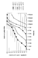
- FIG. 5 is a graph showing the relationship between pH and corrosion. From the test results of immersing the test piece in an ammonia solution of different pH in the oxygen saturated (25 ° C, 8mg / l), room temperature test condition in a sealed container, the presence or absence of corrosion is judged from the surface properties, and the entire corrosion area is determined. It is shown as a percentage of the area.
- the water supply system 11 is filled with can water having a pH included in the storage pH range during storage of the coal gasification combined power generation facility 10 stopped.
- the water supply system 11 can be stored so as not to corrode during storage of the coal gasification combined power generation facility 10 stopped.
- the restart operation is executed after the coal gasification combined power generation facility 10 is stopped for a predetermined period after the storage operation is executed.
- the coal gasification combined cycle power plant 10 is different from the start of the restart operation after filling the storage water containing hydrazine during storage of the conventional equipment, withdrawing the can water from the water supply system 11, and again, The operation is resumed and the normal operation is performed without supplying canned water that satisfies the water quality during the normal operation.
- the coal gasification combined cycle power plant 10 restarts by not replacing the can water whose pH is included in the storage pH range with the can water whose pH is included in the operation pH range. Can be shortened in a shorter time than a conventional restart operation.
- the comparative example of the boiler operation method is executed as an embodiment of the conventional equipment storage method using the coal gasification combined power generation facility 10 in the same manner as the boiler operation method in the above-described embodiment.
- the storage operation in the embodiment is replaced with another storage operation, and the restart operation in the above-described embodiment is replaced with another restart operation.
- step S1 canned water is extracted from the water supply system 11 (step S2).
- the water supply system 11 is filled with storage water after the can water is extracted.
- the storage water contains 50 mg / L of hydrazine.
- the water supply system 11 exhausts air containing oxygen from the space filled with gas in the water supply system 11 by pressurizing and injecting nitrogen. Is filled in the space (step S2).
- the water supply system 11 is filled with storage water containing 50 mg / L of hydrazine while the coal gasification combined power generation facility 10 is stopped. Corrosion of the steel constituting the water supply system 11 can be suppressed.
- step S3 storage water containing hydrazine having a higher concentration than hydrazine suitable for normal operation is extracted from the water supply system 11 (step S3).
- the water supply system 11 is filled with canned water after the storage water is extracted (step S4).
- Canned water is formed from water that does not contain hydrazine.
- the coal gasification combined cycle power generation facility 10 is resumed in operation after the water supply system 11 is filled with can water, and a normal operation is performed.
- the combined coal gasification combined power generation facility 10 is properly operated in a normal operation by circulating canned water not containing hydrazine through the water supply system 11. Can.
- ammonia is generally easier to obtain than hydrazine and can be handled more easily.
- the restarting operation after storage of the device in the above-described embodiment does not extract canned water from the water supply system 11 before storing the water supply system 11, that is, it is included in the storage pH range by injecting an ammonia solution. Compared with the restart operation after storing the equipment in the comparative example, it is possible to reduce the cost in a shorter time and without discarding the can water Can be executed.
- the restart operation in the above-described embodiment is for stopping the coal gasification combined power generation facility 10 and starting storage of equipment by not extracting the canned water filled in the water supply system 11 during storage of the equipment.
- the process of filling the water supply system 11 with storage water containing hydrazine can be omitted, and the hydrazine is contained from the water supply system 11 for further restart.
- the step of filling can water can be omitted.
- the coal gasification combined power generation facility 10 can be stopped in a shorter time, and can be shortened in a shorter time. Can be restarted.
- the operation executed by the control device 15 can be executed by the user. That is, the user measures the pH of the canned water stored in the steam drum 16 of the gas cooler 2 by controlling the pH measuring device 14.
- the ammonia addition facility 12 By operating the ammonia addition facility 12, the ammonia solution is added to the pipe line 30 or the addition of the ammonia solution is stopped.
- the coal gasification combined cycle power generation facility 10 can be more easily prevented from corroding and can be stopped in a shorter time in the same manner as the boiler operation method in the above-described embodiment. Can be restarted in a shorter time. That is, since the gas cooler 2 and the exhaust heat recovery boiler include the boiler, the above-described effects can be achieved.
- the boiler includes a water supply system through which heated can water flows, an ammonia addition facility for adding ammonia to the can water, and a pH measuring device for measuring the pH of the can water.
- the storage control circuit 22 in the above-described embodiment is replaced with another storage control circuit.
- the storage control circuit records a plurality of storage pH ranges corresponding to a plurality of storage periods in the storage device in advance.
- Each of the plurality of storage pH ranges has a lower limit equal to or greater than the set value of the operating pH range.
- the lower limit of the storage pH range corresponding to a period of 24 hours or less shows 9.5.
- the lower limit of the storage pH range corresponding to a period of 72 hours or less indicates 9.7.
- the lower limit of the storage pH range corresponding to the period included from 4 days to 7 days is 9.8.
- the lower limit of the storage pH range corresponding to the period included from 7 days to 14 days is 9.9.
- the lower limit of the pH range for storage corresponding to a period included in 15 days to 30 days indicates 10.
- the upper limit of storage pH is preferably less than pH 11.
- the present invention is not limited to this.
- the storage operation unit calculates a storage pH range corresponding to the storage period from a plurality of storage pH ranges when the storage period is input from the user to the control device 15.
- the storage operation unit controls the pH measurement device 14 so that the pH of the can water stored in the steam drum 16 is measured.
- the storage control circuit further controls the ammonia addition facility 12 so that the pH of the can water stored in the steam drum 16 is included in the storage pH range. Further, the storage pH range corresponding to the storage period is calculated, and the ammonia addition facility 12 may be operated not only by controlling the ammonia addition facility 12 but also by manual operation.
- the coal gasification combined cycle facility provided with such a storage control circuit can more easily suppress corrosion of the water supply system 11 in the same manner as the coal gasification combined cycle facility 10 in the embodiment described above. Can be stopped in a shorter time, and can be restarted in a shorter time.
- FIG. 5 shows the relationship between the pH of stored water and corrosion.
- the relationship indicates the pH of the storage water in which the specimen formed from steel is immersed, and the corrosion area with respect to the number of days that the specimen is immersed in the storage water.
- the corrosion area indicates the ratio of the surface area of the area where the specimen is corroded in the number of elapsed days to the area of the surface in contact with the storage water.
- the relationship shows that corrosion progresses with time.
- the relationship further indicates that the higher the pH of the storage water, the later the test material begins to corrode. For this reason, the relationship has shown that corrosion can be prevented for a longer period, so that the pH of the can water with which the water supply system 11 in storage is filled is large.
- the coal gasification combined cycle power generation facility equipped with such a storage control circuit increases the lower limit of the storage pH range as the storage period to be stopped is longer, so that the ammonia used for storage of the water supply system 11 is increased.
- the amount of addition can be reduced, and corrosion of the water supply system 11 can be prevented appropriately.
- the storage pH range can be replaced with another storage pH range having a lower limit of 9.5.
- the lower limit of the storage pH range is equal to the set value of the operating pH range or larger than the set value of the operating pH range.
Landscapes
- Engineering & Computer Science (AREA)
- Chemical & Material Sciences (AREA)
- Combustion & Propulsion (AREA)
- Mechanical Engineering (AREA)
- General Engineering & Computer Science (AREA)
- Physics & Mathematics (AREA)
- Thermal Sciences (AREA)
- Life Sciences & Earth Sciences (AREA)
- Sustainable Development (AREA)
- Sustainable Energy (AREA)
- Preventing Corrosion Or Incrustation Of Metals (AREA)
Abstract
Description
一方、定期点検などで石炭ガス化複合発電設備の運転が停止して、機器保管中となる期間が長い場合、給水系統の配管等を交換する必要があるときは缶水を排出して対応する。しかし、速やかに再起動するため缶水を排出しないで保管する場合において、給水系統の配管内部など金属製構成材が腐食することを防止することが望まれている。
また、例えば、高温、強アルカリ性(pH11以上)環境では、通常アルカリに強い鋼鉄でもアルカリ腐食となる可能性があるため、保管用pHの上限はpH11未満が好ましい。しかし、これに限定するものではない。
2 :ガス冷却器
3 :ガスタービン
5 :排熱回収ボイラ
6 :蒸気タービン
10:石炭ガス化複合発電設備
11:給水系統
12:アンモニア添加設備
14:pH測定装置
15:制御装置
21:通常制御回路
22:保管用制御回路
Claims (8)
- 缶水が流れる給水系統と、
前記缶水にアンモニア溶液を添加するアンモニア添加設備と、を備えるボイラを用いて実行されるボイラ運転方法であり、
前記缶水のpHを測定すること、
前記ボイラの運転に当たり、前記pHが運転用pH範囲に含まれているときに、前記缶水が加熱されるように前記缶水を前記給水系統に流すこと、
前記ボイラの停止に当たり、前記pHが保管用pH範囲に含まれるまで前記缶水にアンモニア溶液が添加されるように、前記アンモニア添加設備を制御すること、
前記pHが前記保管用pH範囲に含まれているときに前記給水系統に前記缶水が流れるのを停止させることを備え、
前記保管用pH範囲に含まれる任意のpHは、前記運転用pH範囲に含まれる任意のpHと等しい/または前記任意のpHより大きいボイラ運転方法。 - 前記給水系統に前記缶水が流れるのを停止させた後で、前記ボイラの再起動運転に当たり、前記pHが前記運転用pH範囲に含まれているときに、前記缶水が加熱されるように前記給水系統に前記缶水を流すことをさらに備える請求項1に記載されるボイラ運転方法。
- 複数の保管期間を複数の保管用pH範囲に対応付けるテーブルを参照して、前記給水系統に前記缶水を流さない発電設備停止期間に対応する前記保管用pH範囲を前記複数の保管用pH範囲から導くことをさらに備え、
前記複数の保管用pH範囲のうちの第1期間に対応する第1保管用pH範囲の下限は、前記複数の保管用pH範囲のうちの前記第1期間より長い第2期間に対応する第2保管用pH範囲の下限より大きい請求項1または請求項2に記載されるボイラ運転方法。 - 前記第1保管用pH範囲の下限、および第2保管用pH範囲の下限は、9.5から10の範囲の数値である請求項3に記載されるボイラ運転方法。
- 缶水が流れる給水系統と、
前記缶水にアンモニア溶液を添加するアンモニア添加設備と、
前記缶水のpHを測定するpH測定装置と、
制御装置と、を備えるボイラであって、
前記ボイラの運転に当たり、前記制御装置は、
前記缶水が加熱されるように前記缶水が前記給水系統を流れるときに、前記pHが保管用pH範囲に含まれるように、前記アンモニア添加装置を制御する通常制御回路と、
前記ボイラの停止に当たり、前記缶水が前記給水系統を流れることが停止される前に、前記pHが保管用pH範囲に含まれるように、前記アンモニア添加設備を制御する保管用制御回路と、を備え、
前記保管用pH範囲に含まれる任意のpHは、前記運転用pH範囲に含まれる任意のpHと等しい/または前記任意のpHより大きいボイラ。 - 請求項5に記載されるボイラと、
炭素含有固体燃料をガス化することにより生成される生成ガスが流れる流路と、を備え、
前記給水系統は、前記生成ガスの熱を用いて前記缶水を加熱するガス冷却器。 - 請求項5に記載されるボイラと、
ガスタービンから排気された排ガスが流れる流路と、を備え、
前記給水系統は、前記排ガスの熱を用いて前記缶水を加熱する排熱回収ボイラ。 - 請求項5に記載されるボイラと、
炭素含有固体燃料をガス化することにより生成ガスを生成するガス化炉と、
前記生成ガスを用いて動力を生成することにより排ガスを排気するガスタービンと、
蒸気を用いて動力を生成する蒸気タービンと、を備え、
前記蒸気は、前記給水系統が前記生成ガスの熱と前記排ガスの熱とを用いて前記缶水を加熱することにより生成される石炭ガス化複合発電設備。
Priority Applications (3)
| Application Number | Priority Date | Filing Date | Title |
|---|---|---|---|
| CN201480007517.1A CN105008800B (zh) | 2013-02-20 | 2014-01-20 | 锅炉运转方法及锅炉 |
| KR1020157021388A KR101728263B1 (ko) | 2013-02-20 | 2014-01-20 | 보일러 운전 방법 및 보일러 |
| US14/767,724 US20150377078A1 (en) | 2013-02-20 | 2014-01-20 | Boiler operation method and boiler |
Applications Claiming Priority (2)
| Application Number | Priority Date | Filing Date | Title |
|---|---|---|---|
| JP2013-031404 | 2013-02-20 | ||
| JP2013031404A JP5960077B2 (ja) | 2013-02-20 | 2013-02-20 | ボイラ運転方法およびボイラ |
Publications (1)
| Publication Number | Publication Date |
|---|---|
| WO2014129244A1 true WO2014129244A1 (ja) | 2014-08-28 |
Family
ID=51391041
Family Applications (1)
| Application Number | Title | Priority Date | Filing Date |
|---|---|---|---|
| PCT/JP2014/050970 Ceased WO2014129244A1 (ja) | 2013-02-20 | 2014-01-20 | ボイラ運転方法およびボイラ |
Country Status (5)
| Country | Link |
|---|---|
| US (1) | US20150377078A1 (ja) |
| JP (1) | JP5960077B2 (ja) |
| KR (1) | KR101728263B1 (ja) |
| CN (1) | CN105008800B (ja) |
| WO (1) | WO2014129244A1 (ja) |
Cited By (4)
| Publication number | Priority date | Publication date | Assignee | Title |
|---|---|---|---|---|
| CN107073365A (zh) * | 2015-05-28 | 2017-08-18 | 三浦工业株式会社 | 压载水处理装置以及压载水处理方法 |
| WO2019077832A1 (ja) * | 2017-10-17 | 2019-04-25 | 三菱日立パワーシステムズ株式会社 | 給水系統における海水の漏洩検出装置及び方法並びに蒸気タービンプラント |
| WO2020137496A1 (ja) * | 2018-12-27 | 2020-07-02 | 三菱日立パワーシステムズ株式会社 | ボイラプラントの洗浄保管方法および洗浄保管装置 |
| CN114074982A (zh) * | 2020-08-14 | 2022-02-22 | 云南聚杰环保科技有限公司 | 一种工业汽包炉汽包水加碱性强电解质防腐防垢技术 |
Families Citing this family (5)
| Publication number | Priority date | Publication date | Assignee | Title |
|---|---|---|---|---|
| JP6420729B2 (ja) * | 2015-07-02 | 2018-11-07 | 三菱日立パワーシステムズ株式会社 | 排ガスから湿分を回収する火力発電設備及びその火力発電設備の回収水の処理方法 |
| JP6830072B2 (ja) * | 2018-01-22 | 2021-02-17 | 水ing株式会社 | ボイラの防食方法及びボイラ設備 |
| CN111412965A (zh) * | 2020-04-01 | 2020-07-14 | 江苏核电有限公司 | 一种二回路化学工况调节系统试剂箱液位报警设置方法 |
| JP7581079B2 (ja) | 2021-02-24 | 2024-11-12 | 三菱重工業株式会社 | ボイラの保管装置およびこれを備えたボイラならびにボイラの保管方法 |
| CN115773492B (zh) * | 2022-12-02 | 2026-05-15 | 浙江浙能技术研究院有限公司 | 一种用于燃机余热锅炉快速启动的湿法充氮保养方法 |
Citations (5)
| Publication number | Priority date | Publication date | Assignee | Title |
|---|---|---|---|---|
| JPS63105302A (ja) * | 1986-10-22 | 1988-05-10 | バブコツク日立株式会社 | 発電プラントにおける給水処理方法 |
| JPH076606B2 (ja) * | 1985-05-08 | 1995-01-30 | 株式会社日立製作所 | 複合発電プラントの水処理方法 |
| JPH08219405A (ja) * | 1995-02-16 | 1996-08-30 | Kyushu Electric Power Co Inc | ボイラ設備の防食方法 |
| JP2004169992A (ja) * | 2002-11-20 | 2004-06-17 | Chubu Electric Power Co Inc | ボイラの管理方法 |
| JP2008075983A (ja) * | 2006-09-22 | 2008-04-03 | Chugoku Electric Power Co Inc:The | 発電プラントの停止・起動時の水処理方法及びその装置 |
Family Cites Families (15)
| Publication number | Priority date | Publication date | Assignee | Title |
|---|---|---|---|---|
| US4905721A (en) * | 1989-05-11 | 1990-03-06 | Betz Laboratories, Inc. | Monitoring and controlling AVT (all volatile treatment) and other treatment programs for high pressure boilers via the conductivity control method |
| US5327330A (en) * | 1993-04-07 | 1994-07-05 | Ford Motor Company | Inner sealed lamp-within-a lamp headlamp for a motor vehicle |
| DE69402138T2 (de) * | 1993-08-20 | 1997-10-16 | Nalco Chemical Co | System zur Regelung eines Kessels nach einem PH/phosphat-Programm |
| US7328170B2 (en) * | 2001-02-02 | 2008-02-05 | Optimal Robotics Corporation | Multi-device supervisor support for self-checkout systems |
| KR100569761B1 (ko) * | 2004-09-23 | 2006-04-11 | 주식회사 포스코 | 보일러의 수질상태 진단 및 자동제어장치와 방법 |
| WO2006073619A2 (en) * | 2004-11-30 | 2006-07-13 | Ashland Licensing And Intellectual Property Llc | Automated process for inhibiting corrosion in an inactive boiler containing an aqueous system |
| US7243618B2 (en) * | 2005-10-13 | 2007-07-17 | Gurevich Arkadiy M | Steam generator with hybrid circulation |
| US8075646B2 (en) * | 2006-02-09 | 2011-12-13 | Siemens Energy, Inc. | Advanced ASU and HRSG integration for improved integrated gasification combined cycle efficiency |
| JP4983069B2 (ja) * | 2006-03-31 | 2012-07-25 | 栗田工業株式会社 | 純水給水ボイラ水系処理方法および処理装置 |
| JP2008057888A (ja) | 2006-08-31 | 2008-03-13 | Mitsubishi Heavy Ind Ltd | 蒸気プラントの水処理方法 |
| US20110070123A1 (en) | 2008-03-27 | 2011-03-24 | Jan Stodola | Corrosion reduction system for power generation plants during shutdown |
| JP5439942B2 (ja) * | 2009-05-14 | 2014-03-12 | 栗田工業株式会社 | 簡易ボイラにおける水処理剤添加方法 |
| JP2010185655A (ja) * | 2010-04-01 | 2010-08-26 | Miura Co Ltd | ボイラ装置の腐食抑制方法 |
| CN102519030A (zh) * | 2012-01-10 | 2012-06-27 | 广东电网公司电力科学研究院 | 一种热力设备停运保养方法 |
| CN102838227A (zh) * | 2012-08-16 | 2012-12-26 | 浙江东发环保工程有限公司 | 将工业园区中水处理为电厂锅炉补给水的处理系统及方法 |
-
2013
- 2013-02-20 JP JP2013031404A patent/JP5960077B2/ja active Active
-
2014
- 2014-01-20 US US14/767,724 patent/US20150377078A1/en not_active Abandoned
- 2014-01-20 KR KR1020157021388A patent/KR101728263B1/ko not_active Expired - Fee Related
- 2014-01-20 CN CN201480007517.1A patent/CN105008800B/zh active Active
- 2014-01-20 WO PCT/JP2014/050970 patent/WO2014129244A1/ja not_active Ceased
Patent Citations (5)
| Publication number | Priority date | Publication date | Assignee | Title |
|---|---|---|---|---|
| JPH076606B2 (ja) * | 1985-05-08 | 1995-01-30 | 株式会社日立製作所 | 複合発電プラントの水処理方法 |
| JPS63105302A (ja) * | 1986-10-22 | 1988-05-10 | バブコツク日立株式会社 | 発電プラントにおける給水処理方法 |
| JPH08219405A (ja) * | 1995-02-16 | 1996-08-30 | Kyushu Electric Power Co Inc | ボイラ設備の防食方法 |
| JP2004169992A (ja) * | 2002-11-20 | 2004-06-17 | Chubu Electric Power Co Inc | ボイラの管理方法 |
| JP2008075983A (ja) * | 2006-09-22 | 2008-04-03 | Chugoku Electric Power Co Inc:The | 発電プラントの停止・起動時の水処理方法及びその装置 |
Cited By (10)
| Publication number | Priority date | Publication date | Assignee | Title |
|---|---|---|---|---|
| CN107073365A (zh) * | 2015-05-28 | 2017-08-18 | 三浦工业株式会社 | 压载水处理装置以及压载水处理方法 |
| WO2019077832A1 (ja) * | 2017-10-17 | 2019-04-25 | 三菱日立パワーシステムズ株式会社 | 給水系統における海水の漏洩検出装置及び方法並びに蒸気タービンプラント |
| JP2019074274A (ja) * | 2017-10-17 | 2019-05-16 | 三菱日立パワーシステムズ株式会社 | 給水系統における海水の漏洩検出装置及び方法並びに蒸気タービンプラント |
| KR20200053546A (ko) * | 2017-10-17 | 2020-05-18 | 미츠비시 히타치 파워 시스템즈 가부시키가이샤 | 급수 계통에 있어서의 해수의 누설 검출 장치 및 방법 및 증기 터빈 플랜트 |
| KR102385496B1 (ko) * | 2017-10-17 | 2022-04-11 | 미츠비시 파워 가부시키가이샤 | 급수 계통에 있어서의 해수의 누설 검출 장치 및 방법 및 증기 터빈 플랜트 |
| US11802688B2 (en) | 2017-10-17 | 2023-10-31 | Mitsubishi Heavy Industries, Ltd. | Seawater leakage detection device in feedwater system, method for detecting seawater leakage in feedwater system, and steam turbine plant |
| WO2020137496A1 (ja) * | 2018-12-27 | 2020-07-02 | 三菱日立パワーシステムズ株式会社 | ボイラプラントの洗浄保管方法および洗浄保管装置 |
| JP2020106199A (ja) * | 2018-12-27 | 2020-07-09 | 三菱日立パワーシステムズ株式会社 | ボイラプラントの洗浄保管方法および洗浄保管装置 |
| JP7150594B2 (ja) | 2018-12-27 | 2022-10-11 | 三菱重工業株式会社 | ボイラプラントの洗浄保管方法および洗浄保管装置 |
| CN114074982A (zh) * | 2020-08-14 | 2022-02-22 | 云南聚杰环保科技有限公司 | 一种工业汽包炉汽包水加碱性强电解质防腐防垢技术 |
Also Published As
| Publication number | Publication date |
|---|---|
| CN105008800B (zh) | 2017-03-08 |
| JP2014159925A (ja) | 2014-09-04 |
| KR20150104610A (ko) | 2015-09-15 |
| KR101728263B1 (ko) | 2017-04-18 |
| US20150377078A1 (en) | 2015-12-31 |
| JP5960077B2 (ja) | 2016-08-02 |
| CN105008800A (zh) | 2015-10-28 |
Similar Documents
| Publication | Publication Date | Title |
|---|---|---|
| JP5960077B2 (ja) | ボイラ運転方法およびボイラ | |
| JP5420750B2 (ja) | 高効率蒸気発生装置および方法 | |
| JP2014159925A5 (ja) | ||
| JP2007205187A (ja) | ボイラ−蒸気タービンシステムに付属させる熱回収システム | |
| JP5636955B2 (ja) | 熱回収利用システム | |
| JP2018123689A (ja) | バイオマス発電システム | |
| CN105066720B (zh) | 一种烧结冷却机余热利用系统 | |
| JP5984506B2 (ja) | 硫酸製造設備における廃熱の利用方法及びそのシステム | |
| US9163827B2 (en) | System and method for using boiler feedwater | |
| JP6242951B2 (ja) | ボイラ運転方法およびボイラ | |
| CN204987905U (zh) | 一种烧结冷却机余热利用系统 | |
| CN120466637A (zh) | 一种新型转炉烟气余热锅炉热力除氧器的加热控制方式 | |
| JP2012117680A (ja) | 発電システム | |
| JPH11325406A (ja) | 火力発電設備における給水加熱装置 | |
| JP2016017716A (ja) | 排熱回収システム及び排熱回収システムのメンテナンス方法 | |
| US11946005B2 (en) | Gasification gas treatment facility and gasification gas treatment method | |
| JP4823998B2 (ja) | 廃棄物発電方法 | |
| JP2009168269A (ja) | 発電停止時の発電装置の制御方法 | |
| JP2009281168A (ja) | 汽力発電設備における復水系統及びその運転方法 | |
| JP7380309B2 (ja) | ボイラの化学洗浄方法 | |
| JP6651826B2 (ja) | 水素利用システム及び方法 | |
| Larin et al. | Import Substituting Water-Chemistry Technologies on the Basis of Amine-Containing Reagents for Combined-Cycle Power Plant Steam Generators | |
| JP2008101856A (ja) | 廃棄物処理設備のボイラ過熱器の運転方法及び廃棄物処理設備のボイラ過熱器 | |
| JP2024054719A (ja) | ボイラ給水装置およびボイラ給水方法 | |
| KR20260017392A (ko) | 열원을 이용하여 프로세스 증기를 제공하기 위한 설비 및 방법 |
Legal Events
| Date | Code | Title | Description |
|---|---|---|---|
| 121 | Ep: the epo has been informed by wipo that ep was designated in this application |
Ref document number: 14754149 Country of ref document: EP Kind code of ref document: A1 |
|
| ENP | Entry into the national phase |
Ref document number: 20157021388 Country of ref document: KR Kind code of ref document: A |
|
| WWE | Wipo information: entry into national phase |
Ref document number: 14767724 Country of ref document: US Ref document number: IDP00201504966 Country of ref document: ID |
|
| NENP | Non-entry into the national phase |
Ref country code: DE |
|
| 122 | Ep: pct application non-entry in european phase |
Ref document number: 14754149 Country of ref document: EP Kind code of ref document: A1 |