WO2014129193A1 - 機器状況表示方法及び機器状況表示装置 - Google Patents
機器状況表示方法及び機器状況表示装置 Download PDFInfo
- Publication number
- WO2014129193A1 WO2014129193A1 PCT/JP2014/000884 JP2014000884W WO2014129193A1 WO 2014129193 A1 WO2014129193 A1 WO 2014129193A1 JP 2014000884 W JP2014000884 W JP 2014000884W WO 2014129193 A1 WO2014129193 A1 WO 2014129193A1
- Authority
- WO
- WIPO (PCT)
- Prior art keywords
- time
- image
- reservation
- start time
- status display
- Prior art date
Links
Images


Classifications
-
- G—PHYSICS
- G06—COMPUTING; CALCULATING OR COUNTING
- G06F—ELECTRIC DIGITAL DATA PROCESSING
- G06F3/00—Input arrangements for transferring data to be processed into a form capable of being handled by the computer; Output arrangements for transferring data from processing unit to output unit, e.g. interface arrangements
- G06F3/01—Input arrangements or combined input and output arrangements for interaction between user and computer
- G06F3/048—Interaction techniques based on graphical user interfaces [GUI]
- G06F3/0487—Interaction techniques based on graphical user interfaces [GUI] using specific features provided by the input device, e.g. functions controlled by the rotation of a mouse with dual sensing arrangements, or of the nature of the input device, e.g. tap gestures based on pressure sensed by a digitiser
- G06F3/0488—Interaction techniques based on graphical user interfaces [GUI] using specific features provided by the input device, e.g. functions controlled by the rotation of a mouse with dual sensing arrangements, or of the nature of the input device, e.g. tap gestures based on pressure sensed by a digitiser using a touch-screen or digitiser, e.g. input of commands through traced gestures
-
- H—ELECTRICITY
- H04—ELECTRIC COMMUNICATION TECHNIQUE
- H04N—PICTORIAL COMMUNICATION, e.g. TELEVISION
- H04N21/00—Selective content distribution, e.g. interactive television or video on demand [VOD]
- H04N21/40—Client devices specifically adapted for the reception of or interaction with content, e.g. set-top-box [STB]; Operations thereof
- H04N21/41—Structure of client; Structure of client peripherals
- H04N21/422—Input-only peripherals, i.e. input devices connected to specially adapted client devices, e.g. global positioning system [GPS]
- H04N21/42204—User interfaces specially adapted for controlling a client device through a remote control device; Remote control devices therefor
-
- H—ELECTRICITY
- H04—ELECTRIC COMMUNICATION TECHNIQUE
- H04N—PICTORIAL COMMUNICATION, e.g. TELEVISION
- H04N21/00—Selective content distribution, e.g. interactive television or video on demand [VOD]
- H04N21/40—Client devices specifically adapted for the reception of or interaction with content, e.g. set-top-box [STB]; Operations thereof
- H04N21/47—End-user applications
- H04N21/472—End-user interface for requesting content, additional data or services; End-user interface for interacting with content, e.g. for content reservation or setting reminders, for requesting event notification, for manipulating displayed content
-
- H—ELECTRICITY
- H04—ELECTRIC COMMUNICATION TECHNIQUE
- H04N—PICTORIAL COMMUNICATION, e.g. TELEVISION
- H04N21/00—Selective content distribution, e.g. interactive television or video on demand [VOD]
- H04N21/40—Client devices specifically adapted for the reception of or interaction with content, e.g. set-top-box [STB]; Operations thereof
- H04N21/47—End-user applications
- H04N21/485—End-user interface for client configuration
Definitions
- the present invention relates to a device status display method for displaying the operation status of a device on a terminal and a device status display device for displaying the operation status of the device.
- AV Audio Visual
- household appliances such as washing machines, air conditioners, air purifiers, scales, rice cookers, microwave ovens, and refrigerators can be connected to the Internet.
- the operation information or reservation information of the home appliance is transmitted to the server through the Internet, and the received operation information or reservation information is accumulated and analyzed in the server.
- Patent Document 1 describes a reserved driving system that can reserve a plurality of devices in accordance with the lifestyle habits of a plurality of families.
- a small terminal is lightweight and small, and can be carried when going out or at home, and can be used at a place away from home appliances installed in the home.
- a small terminal has a small display screen, there is a problem in that a confirmation screen for confirming the operation status of conventional household appliances and AV household appliances cannot be displayed.
- the present invention has been made to solve the above problem, and provides a device status display method and a device status display device capable of easily confirming at least one of an operation start time and an operation end time of a device. It is intended.
- An apparatus status display method is an apparatus status display method for displaying an operation status of a device on a terminal, and acquiring at least one of an operation start time and an operation end time of the device; And displaying an operation time image representing at least one of the operation start time and the operation end time in a time series superimposed on a clock image representing the current time.
- At least one of the operation start time and the operation end time of the device can be easily confirmed.
- (A) is a figure which shows the whole image of the service which the control system in this Embodiment provides
- (B) is a figure which shows the example in which an apparatus maker corresponds to a data center operating company
- (C) These are figures which show the example in which both or one of an apparatus manufacturer and a management company corresponds to a data center operating company.
- the temperature at the time of returning to home is lower than expected, so there is a demand to increase the set temperature of the air conditioner that was reserved for the return time or to advance the operation start time of the air conditioner. Further, according to the forecast, there is a large amount of pollen diffusion, so there is a demand for operating the air purifier in time for returning home or for accelerating the operation start time of the reserved air purifier. Not only this but the request
- the weather information browsing screen and the home appliance reservation and reservation change screen are separated, and the confirmation of the weather information and the confirmation of the operation status of the home appliance are simplified as a series of operations. There is also a problem that it cannot be done.
- the conventional system has a problem that it is impossible to make reservations or change reservations for household appliances such as household appliances and AV household appliances while simultaneously referring to weather information and a clock.
- An apparatus status display method is an apparatus status display method for displaying an operation status of a device on a terminal, and acquiring at least one of an operation start time and an operation end time of the device; And displaying an operation time image representing at least one of the operation start time and the operation end time in a time series superimposed on a clock image representing the current time.
- At least one of the operation start time and the operation end time of the device is acquired, and the acquired operation time image representing at least one of the operation start time and the operation end time in time series is a clock image indicating the current time. Is displayed superimposed on.
- the operation content of the device may be further acquired, and an image representing the acquired operation content may be further superimposed on the clock image.
- the clock image includes an image in which a long hand image and a short hand image continuously change, and the operation time image is formed along a circumference around which the long hand image and the short hand image circulate. And may be represented by a band-like region starting from the operation start time and ending at the operation end time.
- the clock image includes an image in which the long hand image and the short hand image continuously change.
- the operation time image is formed along the circumference around which the long hand image and the short hand image circulate, and is represented by a band-like region having the operation start time as the start and the operation end time as the end.
- the operation start time and the operation end time can be displayed more easily on one screen.
- the operation start time includes a history operation start time representing a time when the device has started to operate in the past, and the operation end time represents a history representing a time when the device has finished the operation in the past.
- An operation end time may be included, and the operation time image may include an image continuously connecting the image indicating the history operation start time and the image indicating the history operation end time.
- the operation start time includes a reserved operation start time indicating a time at which the reserved device starts an operation
- the operation end time indicates a time at which the reserved device ends an operation.
- the reservation operation end time may be included, and the operation time image may include an image that continuously connects the image indicating the reservation operation start time and the image indicating the reservation operation end time.
- the method may further include a step of accepting a change in at least one of the reservation operation start time and the reservation operation end time.
- the change of the reservation operation start time is accepted by moving a predetermined object in contact with the position on the display screen corresponding to the displayed reservation operation start time, and the reservation operation displayed
- the change of the reservation operation end time may be accepted by moving a predetermined object in contact with the position on the display screen corresponding to the end time.
- the change of the reservation operation start time is accepted by moving a predetermined object in contact with the position on the display screen corresponding to the displayed reservation operation start time. Further, a change in the reservation operation end time is accepted by moving a predetermined object in contact with the position on the display screen corresponding to the displayed reservation operation end time.
- the reservation operation start time or the reservation operation end time can be easily changed by a simple operation of moving the predetermined object in contact with the position on the display screen corresponding to the reservation operation start time or the reservation operation end time. it can.
- the change of the reservation operation start time and the reservation operation end time is accepted by moving a predetermined object to a position on the display screen corresponding to the displayed operation time image.
- the reservation operation start time and the reservation operation end time can be easily changed by a simple operation of moving a predetermined object in contact with the position on the display screen corresponding to the displayed operation time image.
- the terminal when the change of at least one of the reservation operation start time and the reservation operation end time is accepted, the terminal indicates that at least one of the reservation operation start time and the reservation operation end time has been changed.
- the method may further include a step of notifying.
- the terminal when the change of at least one of the reservation operation start time and the reservation operation end time is accepted, the terminal is notified that at least one of the reservation operation start time and the reservation operation end time has been changed.
- the terminal confirms that at least one of the reservation operation start time and the reservation operation end time has been changed, and the user confirms that at least one of the reservation operation start time and the reservation operation end time has been changed. can do.
- the device may include a plurality of devices, and further include a step of switching the operation time image for each of the plurality of devices.
- the operation time image is switched and displayed for each of the plurality of devices, the operation time image corresponding to the plurality of devices is not displayed in a complicated manner, but the operation time image can be displayed for each device. The operation time image can be confirmed more easily.
- the operation time image may be switched by touching the display screen of the terminal.
- the operation time image since the operation time image is switched and displayed by touching the display screen of the terminal, the operation time image can be switched according to the display target device by a simple operation.
- the operation time image may be switched by pressing a button provided on the terminal.
- the operation time image is switched and displayed when a button provided on the terminal is pressed, the operation time image can be switched according to the display target device by a simple operation.
- the operation time image may be switched by detecting vibration of the terminal.
- the operation time image since the operation time image is switched and displayed when the vibration of the terminal is detected, the operation time image can be switched according to the display target device by a simple operation.
- the operation time image may be switched based on audio information input to the terminal.
- the operation time image since the operation time image is switched and displayed based on the audio information input to the terminal, the operation time image can be switched according to the display target device by a simple operation.
- the method may further include a step of acquiring weather information, and a weather image representing the acquired weather information may be further superimposed on the clock image.
- the weather information is acquired and the weather image representing the acquired weather information is further superimposed on the clock image, the weather information and at least one of the operation start time and the operation end time of the device are displayed. It can be confirmed at the same time.
- the meteorological information may include at least one of weather, temperature, humidity, wind direction, wind speed, precipitation probability, and pollen scattering amount in a predesignated area.
- the weather information includes at least one of the weather, temperature, humidity, wind direction, wind speed, precipitation probability, and pollen scattering amount of the area designated in advance, the weather, temperature, humidity, wind direction, wind speed, At least one of the probability of precipitation and the amount of pollen scattering and at least one of the operation start time and the operation end time of the device can be confirmed simultaneously.
- the weather information may be input by a terminal that exists in a predesignated area.
- weather information is input by a terminal existing in a predesignated area, so that more accurate weather information can be displayed.
- the weather information when it is changed, it may further include a step of notifying the terminal that the weather information has been changed.
- the operation time image can be changed according to the change of the weather information.
- An apparatus status display apparatus is an apparatus status display apparatus that displays an operation status of an apparatus, an acquisition unit that acquires at least one of an operation start time and an operation end time of the apparatus, and an acquisition And a display unit that displays an operation time image representing at least one of the operation start time and the operation end time in a time series in a superimposed manner on a clock image representing the current time.
- At least one of the operation start time and the operation end time of the device is acquired, and the acquired operation time image representing at least one of the operation start time and the operation end time in time series is a clock image indicating the current time. Is displayed superimposed on.
- FIG. 1A is a diagram showing an overall image of services provided by the device status display system in the present embodiment.
- the device status display system includes a group 100, a data center operating company 110, and a service provider 120.
- the group 100 is, for example, a company, an organization, or a home, and may be of any size.
- the group 100 includes a plurality of devices 101 including a device A and a device B, a home gateway 102, and a terminal 103.
- the plurality of devices 101 include devices that can be connected to the Internet (for example, smartphones, personal computers (PCs) or TVs), and devices that cannot be connected to the Internet by themselves (for example, washing machines, air conditioners, or air purifiers) )including.
- the plurality of devices 101 may include devices that are connectable to the Internet via the home gateway 102, even if they are not connectable to the Internet by themselves. Further, the user 10 uses a plurality of devices 101 in the group 100.
- the terminal 103 is, for example, a wristwatch type wearable terminal.
- the terminal 103 may be a wearable terminal worn on the head, a glasses-type wearable terminal, a smartphone, a mobile phone, or a tablet PC.
- the data center operating company 110 has a cloud server 111.
- the cloud server 111 is a virtualization server that cooperates with various devices via the Internet.
- the cloud server 111 mainly manages huge data (big data) that is difficult to handle with a normal database management tool or the like.
- the data center operating company 110 performs data management, management of the cloud server 111, operation of the data center that performs them, and the like. Details of services performed by the data center operating company 110 will be described later.
- the data center operating company 110 is not limited to a company that only manages data or operates the cloud server 111.
- FIG. 1B when a device manufacturer that develops and manufactures one of a plurality of devices 101 is managing data or managing the cloud server 111, The device manufacturer corresponds to the data center operating company 110.
- the data center operating company 110 is not limited to one company.
- FIG. 1C when a device manufacturer and another management company jointly or share data management or operation of the cloud server 111, both or one of them operates the data center. It corresponds to company 110.
- the service provider 120 has a server 121.
- the server 121 here is not limited in scale, and includes, for example, a memory in a personal PC. In some cases, the server 121 does not exist in the service provider 120.
- the home gateway 102 is not essential. For example, when the cloud server 111 manages all data, the home gateway 102 becomes unnecessary. In addition, there may be no device that cannot be connected to the Internet by itself, as in the case where every device in the home is connected to the Internet.
- the terminal 103 may be one of the plurality of devices 101.
- the device A or device B of the group 100 transmits each log information to the cloud server 111 of the data center operating company 110.
- the cloud server 111 accumulates log information of the device A or the device B (arrow 131 in FIG. 1A).
- the log information is information indicating, for example, driving conditions or operation dates / times of the plurality of devices 101.
- the log information includes TV viewing history, recording recording information of the recorder, operation date and time of the washing machine, amount of laundry, opening and closing date and time of the refrigerator or the number of opening and closing of the refrigerator, etc.
- the log information may be provided directly to the cloud server 111 from the plurality of devices 101 themselves via the Internet.
- the log information may be temporarily accumulated in the home gateway 102 from a plurality of devices 101 and provided to the cloud server 111 from the home gateway 102.
- the cloud server 111 of the data center operating company 110 provides the collected log information to the service provider 120 in a certain unit.
- the fixed unit may be a unit that can organize and provide the information collected by the data center operating company 110 to the service provider 120, or may be a unit that the service provider 120 requests.
- the log information is provided in a fixed unit, but it may not be a fixed unit, and the amount of information to be provided may change depending on the situation.
- the log information is stored in the server 121 held by the service provider 120 as necessary (arrow 132 in FIG. 1A).
- the service provider 120 organizes the log information into information suitable for the service provided to the user and provides it to the user.
- the user who provides the service may be the user 10 who uses the plurality of devices 101 or the external user 20.
- the service may be provided directly from the service provider 120 to the users 10 and 20 (arrows 133 and 134 in FIG. 1A).
- the service may be provided to the user 10 through the cloud server 111 of the data center operating company 110 again (arrows 135 and 136 in FIG. 1A).
- the cloud server 111 of the data center operating company 110 may organize the log information into information suitable for the service provided to the user and provide the information to the service provider 120.
- an instruction may be received from the user 20 for the service provided to the user 20 (arrow 137 in FIG. 1A).
- the user 10 may be the same as or different from the user 20.
- FIG. 2 is a block diagram showing the configuration of the device status display system 600 according to the embodiment of the present invention.
- the device status display system 600 displays the status of the device 601 and the device 601 that are one of the plurality of devices 101 belonging to the group 100, and controls the operation of the device 601.
- the device 601 includes a device ID management unit 610, a log information acquisition unit 611, a log information storage unit 612, an input / output unit 613, and a communication unit 614.
- a device ID management unit 610 a log information acquisition unit 611
- a log information storage unit 612 a log information storage unit 612
- an input / output unit 613 a communication unit 614.
- the device ID management unit 610 stores a unique identifier (device ID) for individually identifying the device 601.
- the device ID management unit 610 includes, for example, a non-volatile memory such as a flash memory or an HDD (Hard Disk Drive).
- the log information acquisition unit 611 acquires log information that is information related to an operation performed by the user on the device 601 or information related to the operation of the device 601.
- the log information is, for example, a code number of a washing course set by the user for the washing machine or an operation reservation time set by the user for the washing machine.
- the log information accumulation unit 612 accumulates the log information acquired by the log information acquisition unit 611.
- the log information storage unit 612 is configured by a nonvolatile memory, for example.
- the input / output unit 613 is an input / output device that displays operation information of the device 601 and performs reservation setting of the device 601.
- the input / output unit 613 may be a simple input device such as a button, or may be a complex input device or circuit such as a keyboard or a voice input device.
- the input / output unit 613 may be a simple output device such as an LED (Light Emitting Diode) that indicates a button to be operated next, or a complex output device or circuit such as a display or an audio output device. There may be.
- the input / output unit 613 may be a touch panel.
- the communication unit 614 is input by the unique identifier stored in the device ID management unit 610, the log information acquired by the log information acquisition unit 611, the log information stored in the log information storage unit 612, and the input / output unit 613.
- the transmitted information is transmitted to the data center operating company 110 (cloud server 111) and the service provider 120 (server 121) via the Internet.
- the communication unit 614 receives information output to the input / output unit 613 from the service provider 120 (server 121) or the data center operating company 110 (cloud server 111).
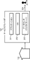
- the terminal 103 includes a touch detection unit 620, a communication unit 621, a weather information acquisition unit 622, a screen display unit 623, a device information acquisition unit 624, and a display information superimposition unit 625.
- a touch detection unit 620 includes a touch detection unit 620, a communication unit 621, a weather information acquisition unit 622, a screen display unit 623, a device information acquisition unit 624, and a display information superimposition unit 625.
- a touch detection unit 620 includes a touch detection unit 620, a communication unit 621, a weather information acquisition unit 622, a screen display unit 623, a device information acquisition unit 624, and a display information superimposition unit 625.
- the touch detection unit 620 detects what input operation the user has performed on the display screen of the terminal 103.
- the user performs input operations such as touch and swipe on the display screen (touch panel).
- the communication unit 621 transmits and receives information to and from the service provider 120 (server 121). Communication between the terminal 103 and the service provider 120 is performed directly via the Internet or a telephone line.
- the terminal 103 may be connected to the service provider 120 via an Internet connection terminal in the proximity of the terminal 103.
- the terminal 103 is a watch-type terminal having only a short-range wireless communication function such as Bluetooth (registered trademark)
- the terminal 103 communicates with a mobile phone held by the user using the short-range wireless communication.
- the service provider 120 is connected via a mobile phone.
- the meteorological information acquisition unit 622 acquires weather information corresponding to a region or a position on a map designated in advance by the user from the service provider 120 via the communication unit 621.
- the weather information includes at least one of a weather forecast, a temperature forecast, a humidity forecast, a wind speed forecast, a wind direction forecast, a precipitation probability forecast, and a pollen scattering quantity forecast.
- the screen display unit 623 presents information to the user.
- the screen display unit 623 is configured with, for example, a touch panel display.
- the device information acquisition unit 624 receives log information indicating the operation status of the device 601 from the service provider 120 via the communication unit 621.
- the operation status includes operation history information and operation reservation information.
- the operation history information includes a history operation start time that represents a time when the device has started to operate in the past, a history operation end time that represents a time when the device has finished operating in the past, and an operation content when the device has operated.
- the operation reservation information includes a reservation operation start time that represents a time at which the reserved device starts operation, a reservation operation end time that represents a time at which the reserved device finishes operation, and a reservation device operation time. Operation content is included.
- the device information acquisition unit 624 transmits the reservation setting information and reservation change information of the device 601 to the service provider 120 via the communication unit 621.
- the reservation setting information includes a reservation operation start time, a reservation operation end time, and an operation content set by the user.
- the reservation change information includes a reservation operation start time, a reservation operation end time, and an operation content changed by the user.
- the display information superimposing unit 625 superimposes the clock image representing the current time, the weather image representing the weather information acquired by the weather information acquiring unit 622, and the screen information obtained by superimposing the device information acquired by the device information acquiring unit 624. And the generated screen information is displayed on the screen display unit 623.
- the device status display system 600 includes one device 601 and one terminal 103, but the device status display system 600 includes two or more devices and two or more terminals. It may be.
- the data center operating company 110 manages the cloud server 111 and the OS 112. Hereinafter, each component constituting the data center operating company 110 will be described.
- the cloud server 111 is a virtualization server that cooperates with various devices via the Internet.
- the cloud server 111 mainly manages huge data (big data) that is difficult to handle with a normal database management tool or the like.
- the OS 112 is system software that provides an interface that abstracts hardware to application software.
- the service provider 120 manages the server 121.
- the server 121 includes a user authentication unit 630, a device search unit 631, a user DB (database) 632, and a device DB 633.
- a user authentication unit 630 includes a user authentication unit 630, a device search unit 631, a user DB (database) 632, and a device DB 633.
- the user authentication unit 630 uses the user ID and password transmitted from the terminal 103 to the service provider 120 (server 121) by the user and information stored in the user DB 632, and the user of the terminal 103 uses the device status display system 600. Check if you are a legitimate service user. That is, the user authentication unit 630 determines whether the user ID and password received from the terminal 103 are the same as the user ID and password stored in the user DB 632. The user authentication unit 630 determines that the user is an authorized service user if the user ID and the password match, and determines that the user is not an authorized service user if the user ID and the password do not match.
- the device search unit 631 specifies the device held by the authorized user authenticated by the user authentication unit 630 by searching from the information stored in the device DB 633.
- the user DB 632 is configured by a secondary storage device, for example, and stores the user ID and password of the service user.
- the user ID and password are transmitted in advance to the server 121 by the terminal 103 and stored in the user DB 632.
- the device DB 633 is configured by a secondary storage device, for example, and stores device information of devices held by the service user.
- the device DB 633 stores a user ID for identifying a user and a device ID for identifying the device in association with each other.
- the device ID is transmitted to the server 121 together with the user ID by the device 601 and stored in the device DB 633.
- the device ID may be transmitted together with the user ID from the terminal 103 to the server 121 and stored in the device DB 633.
- FIG. 3 is a diagram illustrating an example of data stored in the log information storage unit 612.
- the log information storage unit 612 stores the date / time information 700, the operation / state identifier 701, the operation / state data 702, and the transmitted flag 703 in association with each other.
- the date / time information 700 is the date / time when the operation was performed on the device 601 or the date / time when the state of the device 601 was changed.
- the date / time information 700 is data (201212120901091107) obtained by concatenating the year, month, day, and time.
- the operation / state identifier 701 indicates whether the operation / state data 702 is data indicating an operation performed on the device 601 or data indicating the state of the device 601, and the type of the operation / state data 702 is It is an identifier that indicates what it is. For example, a button operation (00000001) on the device and an operation reservation operation (00000002) on the device are operation / status identifiers 701 indicating operations on the device 601, and the power status (10000001) of the device and the reservation setting status of the device are The operation / state identifier 701 indicates the state of the device 601.
- the operation / state data 702 is a specific value indicating an operation performed on the device 601 or a specific value indicating the state of the device 601.
- the operation / state data 702 includes a push button identifier (0001), the number of times of opening / closing the door of the device (0001), a set temperature of the device (18), and a reservation start time of the device.
- the operation / state data 702 includes operation history information and operation reservation information.
- the transmitted flag 703 is an identifier for identifying whether or not the log information stored in the log information storage unit 612 has been transmitted to the cloud server 111 of the data center operating company 110. When transmitted, “1” is accumulated, and when not transmitted, “0” is accumulated.
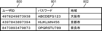
- FIG. 4 is a diagram illustrating an example of data stored in the user DB 632.
- the user DB 632 stores a user ID 800, a password 801, and area information 802 in association with each other.
- the user ID 800 is an identifier uniquely assigned to the service user.
- the password 801 is an arbitrary character string designated by the user.
- the area information 802 is an area designated by the user, and is used when acquiring weather information described later.
- the area information 802 represents, for example, the area where the user lives and the place where the device 601 is installed.
- FIG. 5 is a diagram illustrating an example of data stored in the device DB 633.
- the device DB 633 stores a user ID 900, a device ID 901, model name information 902, and registration date information 903 in association with each other.
- the user ID 900 is an identifier uniquely assigned to the service user, and corresponds to the user ID 800 stored in the user DB 632.
- the device ID 901 is an identifier assigned to a device held by the user corresponding to the user ID 900.
- the device ID 901 is an identifier uniquely assigned to the device.
- the model name information 902 is the name of the device 601.
- the registration date information 903 is the date when the user registered the device 601 with the service, that is, the date when data was stored in the device DB 633.
- FIG. 6 is a flowchart showing an outline of the processing flow of the device status display system 600 according to the present embodiment.
- step S1 the device 601 transmits log information to the cloud server 111 of the data center operating company 110.
- the device 601 transmits the log information stored in the log information storage unit 612 to the cloud server 111 at a predetermined timing.
- the cloud server 111 receives the log information transmitted by the device 601 and stores it in the internal memory.
- step S ⁇ b> 2 the terminal 103 receives the user ID and password input by the user, and transmits the received user ID and password to the server 121 of the service provider 120.
- the server 121 of the service provider 120 receives the user ID and password transmitted by the terminal 103.
- step S3 the server 121 of the service provider 120 acquires log information related to the device corresponding to the user ID of the user received in step S2, from the cloud server 111 of the data center operating company 110.
- step S4 the server 121 of the service provider 120 acquires weather information from the server of the weather information service provider.
- a weather information service provider is a provider that provides a service that provides weather information.
- step S5 the server 121 of the service provider 120 transmits the log information acquired in step S3 and the weather information acquired in step S4 to the terminal 103.
- the terminal 103 receives log information and weather information transmitted by the server 121.
- step S6 the terminal 103 displays the log information and weather information received from the server 121 of the service provider 120 in step S5 superimposed on the clock image representing the current time.
- step S7 the terminal 103 accepts a screen operation by the user, and accepts a change in reservation contents or an addition of reservation contents.
- the terminal 103 transmits reservation change information to the server 121 of the service provider 120.
- the server 121 receives reservation change information transmitted by the terminal 103.
- step S8 the server 121 of the service provider 120 transmits the reservation change information received in step S7 to the cloud server 111.
- the cloud server 111 receives the reservation change information transmitted by the server 121.
- step S9 the cloud server 111 transmits the reservation change information received in step S8 to the device 601.
- the device 601 receives the reservation change information transmitted by the cloud server 111. Accordingly, the device 601 changes the reservation content currently set based on the received reservation change information.
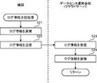
- FIG. 7 is a flowchart showing details of the log information transmission process in step S1 shown in FIG.
- the log information acquisition unit 611 of the device 601 stores the acquired log information in the log information storage unit 612.
- the log information acquisition unit 611 acquires log information related to the operation of the device 601 every time the user performs an operation on the device 601, and stores the acquired log information in the log information storage unit 612. Further, the log information acquisition unit 611 may acquire log information related to the state of the device 601 at a predetermined time interval or may be acquired when a specific operation is performed.
- the log information acquisition unit 611 stores the acquired log information related to the state of the device 601 in the log information storage unit 612 in the same manner as the log information related to the operation of the device 601.
- the transmitted flag 703 of the log information newly accumulated in the log information accumulation unit 612 is “0” indicating that it has not been transmitted yet.
- the communication unit 614 transmits the log information stored in the log information storage unit 612 to the cloud server 111 of the data center operating company 110.
- the device 601 and the cloud server 111 authenticate each other.
- the authentication is performed to prevent the log information of the device 601 from leaking to an unintended server on the Internet, and unintended log information is stored in the cloud server 111 by connecting an unintended device to the cloud server 111. This is to prevent the server 111 from accumulating.
- PKI Public Key Infrastructure
- any authentication method may be used as long as it is an authentication method having a function equivalent to PKI.
- the communication unit 614 of the device 601 transmits the device ID of the device 601 stored in the device ID management unit 610 and the log information stored in the log information storage unit 612 to the cloud server 111.
- the device 601 and the cloud server 111 may perform user authentication in addition to mutual authentication.
- the log information acquisition unit 611 rewrites the transmitted flag 703 of the log information stored in the log information storage unit 612 to “1” indicating that the transmission has been completed.
- the log information whose transmission flag 703 is “1” indicating that transmission has been completed may be deleted in order to improve the efficiency of the storage area.
- the log information to be transmitted to the cloud server 111 is not necessarily stored in the log information storage unit 612. That is, the communication unit 614 may directly transmit the log information acquired by the log information acquisition unit 611 without storing the log information in the log information storage unit 612.
- step S23 the communication unit of the cloud server 111 receives the device ID and log information transmitted by the device 601.
- step S24 the communication unit of the cloud server 111 stores the log information for each device ID in the internal memory using the received device ID.
- step S2 details of the user ID and password transmission process in step S2 shown in FIG. 6 will be described.
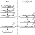
- FIG. 8 is a flowchart showing details of the user ID and password transmission processing in step S2 shown in FIG.
- the touch detection unit 620 of the terminal 103 receives an input of a user ID and a password by the user.
- the user inputs the user ID and password from the input reception screen displayed on the screen display unit 623 of the terminal 103.
- the screen display unit 623 of the terminal 103 displays a software keyboard on the input reception screen.
- the touch detection unit 620 recognizes the user ID and password by detecting the input character.
- step S32 the communication unit 621 of the terminal 103 transmits the user ID and password input by the user in step S31 to the service provider 120.
- the terminal 103 performs server authentication of the service provider 120.
- Server authentication is performed in order to prevent the user ID and password from leaking to an unintended server on the Internet.
- PKI is generally used, but any authentication method may be used as long as it is an authentication method having a function equivalent to PKI.
- the communication unit 621 of the terminal 103 transmits the user ID and password to the server 121 of the service provider 120.
- the communication unit 621 may encrypt and transmit the user ID and password.
- the terminal 103 may accept only the user ID and transmit only the user ID.
- step S33 the communication unit of the server 121 receives the user ID and password transmitted by the terminal 103.
- step S34 the user authentication unit 630 of the server 121 performs user authentication using the user ID and password received from the terminal 103 in step S33.
- the user authentication unit 630 performs user authentication using user information stored in the user DB 632. Specifically, the user authentication unit 630 searches the user DB 632 with the received user ID, and determines whether the user DB 632 has user information corresponding to the user ID. When there is user information corresponding to the user ID, the user authentication unit 630 collates the received password with the password included in the user information. If both passwords match, the user authentication unit 630 determines that the user authentication is successful. On the other hand, when the user information corresponding to the user ID is not in the user DB 632 or the passwords of the two do not match, the user authentication unit 630 determines that the user authentication has failed.
- step S35 the communication unit of the server 121 transmits the result of the user authentication performed in step S34 to the terminal 103.
- the user authentication result may be encrypted.
- step S ⁇ b> 34 the communication unit of the server 121 transmits a user authentication result indicating that user authentication is successful to the terminal 103.
- step S ⁇ b> 34 the communication unit of the server 121 transmits a user authentication result indicating that user authentication has failed to the terminal 103.
- step S36 the communication unit 621 of the terminal 103 receives the user authentication result transmitted by the server 121 of the service provider 120.
- the screen display unit 623 of the terminal 103 displays the user authentication result. Thereby, the user authentication result is notified to the user.
- FIG. 9 is a flowchart showing details of the log information acquisition processing in step S3 shown in FIG.
- step S41 when the device search unit 631 of the server 121 of the service provider 120 determines that user authentication is successful by the user authentication unit 630 in step S34, the user ID that has succeeded in user authentication is used.
- the device ID of the device held by the user is acquired.
- the device search unit 631 searches the device DB 633 using the user ID, and acquires all device IDs corresponding to the user ID.
- step S42 the communication unit of the server 121 of the service provider 120 transmits all the device IDs acquired in step S41 to the cloud server 111 as a device ID list.
- step S43 the communication unit of the cloud server 111 receives the device ID list transmitted by the server 121.
- step S44 the control unit of the cloud server 111 searches the internal memory using the device ID included in the device ID list received in step S43, and acquires device log information corresponding to the device ID. To do.
- control unit of the cloud server 111 does not need to acquire log information corresponding to all device IDs, and may acquire only log information corresponding to device IDs of predetermined devices.
- the predetermined device is, for example, a device that can be reserved for operation, such as a television, a recorder, a washing machine, an air purifier, or an air conditioner.
- the control unit of the cloud server 111 may acquire only log information including at least one of the history operation start time, the history operation end time, the reservation operation start time, and the reservation operation end time.
- step S45 the communication unit of the cloud server 111 transmits the log information acquired in step S44 to the server 121 of the service provider 120.
- step S46 the communication unit of the server 121 of the service provider 120 receives the log information transmitted by the cloud server 111. Thereby, the server 121 can acquire log information related to the device owned by the user.
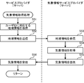
- FIG. 10 is a flowchart showing details of the weather information acquisition process in step S4 shown in FIG.
- step S51 the device search unit 631 of the server 121 of the service provider 120 acquires area information designated in advance by the user using a user ID that has been successfully authenticated.
- the device search unit 631 acquires area information corresponding to the user ID from the user DB 632.
- step S52 the communication unit of the server 121 of the service provider 120 transmits the area information acquired in step S51 to the server of the weather information service provider.
- step S53 the communication unit of the server of the weather information service provider receives the regional information transmitted by the server 121.
- step S54 the control unit of the server of the weather information service provider uses the area information received in step S53 to search and acquire hourly weather information of the area specified by the area information.
- the hourly weather information is information relating to the weather such as hourly weather, temperature, humidity, wind direction, wind speed, precipitation probability, and pollen scattering amount.
- the weather information is not limited to these, and any information may be used as long as it is information related to the weather.
- the weather information may be information provided by a weather forecasting agency or a weather forecasting company, or may be weather information reported by a person in each area.
- the weather information may be input by a terminal existing in a predesignated area. In this case, the terminal transmits the weather information input by the user to the server 121.
- step S55 the communication unit of the server of the weather information service provider transmits the hourly weather information acquired in step S54 to the server 121 of the service provider 120.
- step S56 the communication unit of the server 121 of the service provider 120 receives the hourly weather information transmitted by the server of the weather service provider. Thereby, the server 121 can acquire the weather information of the area previously designated by the user in units of time.
- FIG. 11 is a flowchart showing details of the log information and weather information acquisition process in step S5 shown in FIG.
- step S61 the communication unit of the server 121 of the service provider 120 transmits the log information acquired in step S46 of FIG.
- step S62 the device information acquisition unit 624 of the terminal 103 receives the log information transmitted by the server 121 of the service provider 120 through the communication unit 621. Thereby, the terminal 103 can acquire the log information of the device held by the user.
- step S63 the communication unit of the server 121 of the service provider 120 transmits the hourly weather information acquired in step S56 of FIG.
- step S64 the weather information acquisition unit 622 of the terminal 103 receives the hourly weather information transmitted by the server 121 of the service provider 120 through the communication unit 621. Thereby, the terminal 103 can acquire the weather information of the area designated in advance by the user in units of time.
- the server 121 of the service provider 120 obtains weather information in units of time from the server of the weather information service provider, but this is not necessarily the case.
- the server of the weather information service provider may transmit the changed hourly weather information to the server 121 of the service provider 120.
- the server 121 may notify the terminal 103 that the weather information has been changed.
- the server 121 of the service provider 120 notifies the terminal 103 of change of weather information in units of time.
- the change notification of weather information performs the same process as step S63 shown in FIG.
- the screen display unit 623 of the terminal 103 displays a screen for notifying that the weather information has been changed.
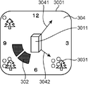
- FIG. 12 is a diagram showing a first example of a display screen displayed in the display process of step S6 shown in FIG.
- the display information superimposing unit 625 creates a display screen 300 in which an operation time image representing at least one of the operation start time and the operation end time on a time series is superimposed on a clock image representing the current time, and the screen display unit 623. Displays the display screen 300 created by the display information superimposing unit 625.
- the display screen 300 includes a device icon 301, an operation time image 302, a weather icon 303, and a clock image 304.
- the clock image 304 is an analog clock and displays the current time.
- the clock image 304 includes an image in which the long hand image 3041 and the short hand image 3042 change continuously.
- the current time is represented by the positions of the long hand image 3041 and the short hand image 3042.
- numerals are arranged in directions indicating 12:00, 3 o'clock, 6 o'clock, and 9 o'clock, respectively.
- the clock image 304 represents 12 hours of morning or afternoon on one screen. That is, the clock image 304 shown in FIG. 12 represents either morning or afternoon time.
- the clock image 304 may represent 24 hours on one screen.
- the device icon 301 is an icon representing the type of device for which the operation time image is to be displayed.
- the display information superimposing unit 625 extracts the device model name from the device log information held by the user received in step S62 in FIG. 11 and superimposes the icon image corresponding to the extracted model name on the clock image 304. To do.
- the device icon 301 is superimposed on the central portion of the clock image 304, that is, the shaft portion of the long hand image 3041 and the short hand image 3042.
- a device icon 301 represents a washing machine icon.
- the operation time image 302 represents the operation start time, the operation end time, and the operation content of the device in time series.
- the operation time image 302 is formed along a circumference around which the long needle image 3041 and the short hand image 3042 circulate, and is represented by a band-like region having the operation start time as the start and the operation end time as the end.
- the operation start time and the operation end time are extracted from the log information of the device held by the user received in step S62 in FIG.
- the operation time image 302 displayed before the current time represents the history operation start time and the history operation end time at which the operation has already ended, and the operation time image 302 displayed after the current time is a reserved operation. It represents the start time and the reservation operation end time.
- FIG. 12 shows that the reservation operation start time of the washing machine is 7:00 pm and the reservation operation end time is 9:00 pm.
- the operation time image 302 includes an image that continuously connects an image indicating the history operation start time and an image indicating the history operation end time.
- the operation time image 302 includes an image that continuously connects an image indicating the reservation operation start time and an image indicating the reservation operation end time.
- the first half of the operation time image 302 indicates the washing time
- the second half of the operation time image 302 indicates the drying time. That is, the area indicating the operation time image 302 is divided into two, the time required for washing is represented by the first half area, and the time required for drying is represented by the second half area. Is done.
- the weather icon 303 is an icon (weather image) indicating weather information for each predetermined time.
- images about the weather and temperature every three hours are displayed.
- the weather and temperature are extracted from the hourly weather information received in step S64 of FIG.
- the first half of the operation time image 302 indicates the washing time
- the second half of the operation time image 302 indicates the drying time.
- the present invention is not particularly limited thereto, and “washing” or The operation content may be indicated by displaying a character image such as “dry”.
- the color of the area indicating the operation time image 302 may be changed according to the operation content. For example, when the operation content of the air conditioner is the cooling operation, the color of the region indicating the operation time image 302 is displayed in blue, and when the operation content of the air conditioner is the heating operation, the color of the region indicating the operation time image 302 May be displayed in red.
- the screen display unit 623 displays the operation time images 302 of the plurality of devices. May be displayed in a switchable manner.
- the user touches the device icon 301 displayed at the center of the screen.
- the screen display unit 623 switches to an icon image corresponding to a different type of device and also switches to the operation time image 302 of the target device.
- the operation time images are switched and displayed in the order of a washing machine, an air conditioner, and an air cleaner, and the operation time images of a plurality of devices can be confirmed together with weather information.
- the screen display unit 623 may switch the operation time image for each of a plurality of devices. Further, the screen display unit 623 may switch the operation time image by touching the display screen of the terminal 103.
- the screen display unit 623 may switch the operation time image by pressing a button provided on the terminal 103 instead of the touch operation. Further, the screen display unit 623 may switch the operation time image when the vibration of the terminal 103 is detected. Further, the screen display unit 623 may switch the operation time image based on audio information input to the terminal 103.
- FIG. 13 is a diagram showing a second example of the display screen displayed in the display process of step S6 shown in FIG.
- the display screen 3001 includes a device icon 3011, an operation time image 302, a weather icon 3031, and a clock image 304.
- the same components as those in the display screen 300 shown in FIG. 13 the same components as those in the display screen 300 shown in FIG.
- FIG. 13 shows an example in which the display target device is an air cleaner.
- the device icon 3011 represents an air cleaner icon.
- the weather icon 3031 represents an image related to the amount of pollen scattered at a predetermined time. In FIG. 13, information on the amount of pollen scattered every 3 hours is displayed. The pollen scattering amount is extracted from the hourly weather information received in step S64 of FIG.
- the weather icon 3031 is displayed in a different manner depending on the amount of pollen scattered. For example, as shown in FIG. 13, a weather icon 3031 with a large number of round marks is used when the amount of pollen scattered is large, and a weather icon 3031 with a small number of round marks is used when the amount of pollen scattered is small. .
- FIG. 14 is a diagram showing a third example of the display screen displayed in the display process of step S6 shown in FIG.
- the display screen 3002 includes a device icon 3012, a first operation time image 3021, a second operation time image 3022, a weather icon 303, and a clock image 304.
- the same components as those of the display screen 300 shown in FIG. 13 the same components as those of the display screen 300 shown in FIG.
- the screen display unit 623 displays a plurality of screen information. All the operation time images of the device are displayed.
- the screen display unit 623 displays a first operation time image 3021 and a second operation time image 3022 corresponding to different devices.
- the first operation time image 3021 represents, for example, the history operation start time and history operation end time of the washing machine
- the second operation time image 3022 represents, for example, the history operation start time and history operation end time of the television. .
- the user touches the displayed operation time image, for example. Thereby, a device icon 3012 indicating a device corresponding to the touched operation time image is displayed in the center.
- a device icon 3012 representing a television is displayed in the center of the screen.
- the display screen 3002 shown in FIG. 14 can also be used for the purpose of watching a child at home roughly from outside the parent. That is, since it is possible to list not only the operation status of each home appliance but the operation status of all home appliances, it is possible to know when the child in the home is using the home appliance.
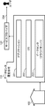
- FIG. 15 is a diagram showing a fourth example of the display screen displayed in the display process of step S6 shown in FIG.
- the display screen 3003 includes a device icon 401, a time axis display area 402, an operation time image 403, a weather icon 404, and a clock image 405.
- the clock image 405 is a digital clock and displays the current time.
- the device icon 401 is an icon representing the type of device for which the operation time image is to be displayed.
- the display information superimposing unit 625 extracts the device model name from the device log information held by the user received in step S62 in FIG. 11 and superimposes the icon image corresponding to the extracted model name on the clock image 405. To do.
- the time axis display area 402 is an area for displaying the operation time image 403 and represents a time axis for one day (24 hours).
- the time axis display area 402 may represent a time axis of 12 hours in the morning or afternoon.
- the operation time image 403 represents the operation start time, operation end time, and operation content of the device.
- the operation time image 403 is formed on the time axis display area 402 representing the time axis, and is represented by a band-like area starting from the operation start time and ending at the operation end time.
- the operation start time and the operation end time are extracted from the log information of the device held by the user received in step S62 in FIG.
- the operation time image 403 displayed before the current time represents the history operation start time and the history operation end time at which the operation has already ended, and the operation time image 403 displayed after the current time is a reserved operation It represents the start time and the reservation operation end time.
- FIG. 15 shows that the reservation operation start time of the washing machine is 7:00 pm and the reservation operation end time is 9:00 pm.
- the first half of the operation time image 4032 indicates the washing time
- the second half of the operation time image 403 indicates the drying time. That is, the area indicating the operation time image 403 is divided into two, the time required for washing is represented by the first half area, and the time required for drying is represented by the second half area. Is done.
- the weather icon 404 is an icon (weather image) indicating weather information for each predetermined time. In FIG. 15, information on the weather and temperature every 6 hours is displayed. The weather and temperature are extracted from the hourly weather information received in step S64 of FIG.
- the color of the area indicating the operation time image 403 may be changed according to the operation content. For example, when the operation content of the air conditioner is the cooling operation, the color of the region indicating the operation time image 403 is displayed in blue, and when the operation content of the air conditioner is the heating operation, the color of the region indicating the operation time image 403 May be displayed in red.
- the screen display unit 623 displays the operation time images 403 of the plurality of devices. May be displayed in a switchable manner.
- the method for switching the operation time image 403 is the same as the switching method on the display screen 300 shown in FIG.
- FIG. 16 is a flowchart showing details of the reservation change acceptance process in step S7 shown in FIG.
- step S71 the touch detection unit 620 of the terminal 103 receives a reservation change. That is, touch detection unit 620 accepts a change in at least one of the reservation operation start time and the reservation operation end time on the display screen displayed in step S6 of FIG.
- the touch detection unit 620 may accept a change in the reserved operation content in addition to the reservation operation start time and the reservation operation end time.
- the touch detection unit 620 may accept a change in both the reservation operation start time and the reservation operation end time, or may accept a change in only one of the reservation operation start time and the reservation operation end time.
- step S72 the communication unit 621 of the terminal 103 sends the reservation change information including the changed reservation operation start time and reservation operation end time to the service provider 120. To the server 121.
- the reservation change information includes information (for example, device ID) for specifying a device whose reservation operation start time and reservation operation end time are to be changed.
- the touch detection unit 620 may accept not only the change of the reservation operation start time and the reservation operation end time displayed on the display screen but also the addition of a new reservation operation start time and a reservation operation end time.
- the communication unit 621 transmits reservation change information including the newly added reservation operation start time and reservation operation end time to the server 121 of the service provider 120.
- step S73 the communication unit of the server 121 of the service provider 120 receives the reservation change information transmitted by the terminal 103. Thereby, the service provider 120 can acquire reservation change information from the user.
- FIG. 17 is a flowchart showing details of the reservation change information transmission process in step S8 shown in FIG.
- step S81 the communication unit of the server 121 of the service provider 120 transmits the reservation change information received in step S73 of FIG. 16 to the cloud server 111.
- step S82 the communication unit of the cloud server 111 receives the reservation change information transmitted by the server 121 of the service provider 120. Thereby, the cloud server 111 can acquire reservation change information from the user.
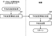
- FIG. 18 is a flowchart showing details of the reservation content changing process in step S9 shown in FIG.
- step S91 the communication unit of the cloud server 111 transmits the reservation change information received in step S82 of FIG. 17 to the reservation change target device 601.
- step S92 the communication unit 614 of the device 601 receives the reservation change information transmitted by the cloud server 111. As a result, the device 601 can acquire reservation change information from the user.
- step S93 the device 601 changes the reservation content using the reservation change information received by the communication unit 614.
- the device 601 changes the currently set reservation operation start time and reservation operation end time to the newly received reservation operation start time and reservation operation end time.
- the device 601 may change the log information stored in the log information storage unit 612 according to the newly received reservation operation start time and reservation operation end time.
- FIG. 19 is a diagram showing an example of a display screen displayed in the reservation change acceptance process in step S7 shown in FIG.
- the reservation change acceptance process performed on the display screen 300 shown in FIG. 12 displayed by the display process in step S6 of FIG. 6 will be described.
- the operation of the washing machine is reserved from 7 pm to 9 pm.
- the user since the night weather forecast has changed to rain, the user is assumed to advance the operation start time of the washing machine by two hours.
- the user touches the operation time image 302 with his / her finger and slides his / her finger along the clock frame while maintaining the state in contact with the screen.
- the touch detection unit 620 receives changes in the reservation operation start time and the reservation operation end time by moving a predetermined object in contact with the position on the display screen corresponding to the displayed operation time image 302. That is, the touch detection unit 620 detects that the finger has touched the position corresponding to the operation time image 302, and detects that the finger has been moved along the clock frame without leaving.
- the screen display unit 623 changes the display position of the operation time image 302 according to the movement of the finger.
- the display position of the operation time image 302 is changed, and the change of the reservation operation start time and the reservation operation end time is accepted.
- the reservation operation start time that was 7:00 pm is changed to 5:00 pm
- the reservation operation end time that was 9:00 pm is changed to 7:00 pm.
- the reservation time can be easily changed by changing the display position of the operation time image 302.
- the touch detection unit 620 accepts a change in the reservation operation start time by moving a predetermined object in contact with the position on the display screen corresponding to the displayed reservation operation start time, and ends the displayed reservation operation.
- a change in the reservation operation end time may be received by moving a predetermined object in contact with a position on the display screen corresponding to the time.
- FIG. 20 and 21 are diagrams showing a second example of the display screen displayed in the reservation change receiving process in step S7 of FIG.
- FIG. 20 is a diagram illustrating an example of a display screen for selecting a device to which reservation contents are added
- FIG. 21 is a diagram illustrating an example of a display screen for adding a reservation operation start time and a reservation operation end time. It is.
- the user touches the device icon 301 at the center of the screen until the air conditioner icon is displayed.
- a display screen 3004 shown in FIG. 20 shows a screen example when the air conditioner icon is displayed.
- the user touches the position corresponding to 7:00 pm as the reservation operation start time, maintains the state of touching the screen, and puts it on the clock frame to the position corresponding to 9:00 pm as the reservation operation end time. Slide your finger along and release your finger at the position corresponding to the scheduled end time.
- the touch detection unit 620 detects that the finger has touched the position corresponding to the reservation operation start time, detects that the finger has moved along the clock frame without leaving, and corresponds to the reservation operation end time.
- the screen display unit 623 displays the operation time image 340 according to the movement of the finger.
- a display screen 3005 shown in FIG. 21 shows a screen example when the operation time image 340 is input. As a result, the user can easily add an air conditioner operation reservation.
- a confirmation message may be displayed on the user's terminal and a confirmation instruction from the user may be accepted.
- FIGS. 12 to 15 and 19 to 21 are merely examples, and any method may be used as long as the display screens and operation methods exhibit the same effects.
- the server 121 of the service provider 120 may perform a reservation change notification indicating a reservation change when another user designated in advance by the user changes the reservation.
- the reservation change content is notified as log information from the server 121 of the service provider 120 to the terminal 103 as in the process of step S5 shown in FIG.
- the communication unit of the server 121 of the service provider 120 indicates that at least one of the reservation operation start time and the reservation operation end time has been changed.
- 103 may be notified.
- the notified terminal 103 is a terminal that has received a change of at least one of the reservation operation start time and the reservation operation end time. Thereby, the user can confirm that at least one of the reservation operation start time and the reservation operation end time has been changed.
- the notified terminal 103 may be a terminal different from the terminal that has received a change in at least one of the reservation operation start time and the reservation operation end time.
- the server 121 Another terminal may be notified that at least one of the reservation operation start time and the reservation operation end time has been changed.
- the server 121 sets the reservation operation start time and reservation in a terminal owned by a father in the same family. It may be notified that at least one of the operation end times has been changed.
- the technology described in the above embodiment can be realized, for example, in the following types of cloud services.
- the type of cloud service in which the technology described in the above aspect is realized is not limited to this.
- FIG. 22 is a diagram showing an overview of services provided by the information device status display system in service type 1 (in-house data center type cloud service).
- the service provider 120 acquires information from the group 100 and provides a service to the user.
- the service provider 120 has a function of a data center operating company. That is, the service provider 120 has a cloud server 203 that manages big data. Therefore, there is no data center operating company.
- the service provider 120 operates and manages the data center (cloud server) 203.
- the service provider 120 manages an operating system (OS) 202 and an application 201.
- the service provider 120 provides a service using the OS 202 and the application 201 managed by the service provider 120 (arrow 204).
- FIG. 23 is a diagram illustrating an overview of services provided by the device status display system in service type 2 (IaaS-based cloud service).
- IaaS is an abbreviation for infrastructure as a service, and is a cloud service provision model that provides a base for constructing and operating a computer system as a service via the Internet.
- the data center operating company 110 operates and manages the data center (cloud server) 203.
- the service provider 120 manages the OS 202 and the application 201.
- the service provider 120 provides a service using the OS 202 and the application 201 managed by the service provider 120 (arrow 204).
- FIG. 24 is a diagram illustrating an overall image of services provided by the device status display system in service type 3 (PaaS use type cloud service).
- PaaS is an abbreviation for Platform as a Service
- PaaS provision model that provides a platform serving as a foundation for constructing and operating software as a service via the Internet.
- the data center operating company 110 manages the OS 202 and operates and manages the data center (cloud server) 203. Further, the service provider 120 manages the application 201. The service provider 120 provides a service using the OS 202 managed by the data center operating company 110 and the application 201 managed by the service provider 120 (arrow 204).
- FIG. 25 is a diagram illustrating an overview of services provided by the device status display system in service type 4 (SaaS-based cloud service).
- SaaS is an abbreviation for software as a service.
- the SaaS-based cloud service is an application provided by a platform provider who owns a data center (cloud server), or a user such as a company or an individual who does not have a data center (cloud server) This is a cloud service provision model with functions that can be used via a network.
- the data center operating company 110 manages the application 201, manages the OS 202, and operates and manages the data center (cloud server) 203.
- the service provider 120 provides a service using the OS 202 and the application 201 managed by the data center operating company 110 (arrow 204).
- the service provider 120 provides a service.
- the service provider or the data center operating company may develop an OS, an application, a big data database, or the like, or may be outsourced to a third party.
- An apparatus status display method and an apparatus status display apparatus can easily check at least one of an operation start time and an operation end time of an apparatus, and display an apparatus status display method on a terminal. It is useful as a device status display device.
Abstract
機器(601)の動作状況を端末(103)に表示する機器状況表示システム(600)における機器状況表示方法は、機器(601)の動作開始時刻及び動作終了時刻の少なくとも一方を取得するステップ(S3)と、取得した動作開始時刻及び動作終了時刻の少なくとも一方を時系列上に表す動作時刻画像を、現在の時刻を表す時計画像に重畳して表示するステップ(S6)とを含む。
Description
本発明は、機器の動作状況を端末に表示する機器状況表示方法及び機器の動作状況を表示する機器状況表示装置に関するものである。
近年、インターネットに接続可能なテレビ又はレコーダなどのAV(Audio Visual)家電が増加し、インターネットを介して映画又はスポーツなどの動画コンテンツを配信する動画配信サービスが提供されている。また、洗濯機、エアコン、空気清浄機、体重計、炊飯器、オーブンレンジ及び冷蔵庫などの生活家電と呼ばれる家電機器もインターネットへの接続が可能となっている。これにより、家電機器の操作情報又は予約情報がインターネットを通じてサーバに送信され、サーバにおいて、受信された操作情報又は予約情報が蓄積されるとともに分析される。
また、サーバに蓄積される情報を利用して、ユーザに様々なサービスが提供されている。例えば、特許文献1には、複数の家族の生活習慣に応じて複数の機器の予約を行うことができる予約運転システムが記載されている。
さらに、端末装置の高機能化及び小型化に伴い、ポータブル型又はリストバンド型の小型端末が普及している。小型端末は軽量及び小型という特徴から外出時又は宅内でも携帯することができ、家庭内に配置された家電から離れた場所でも利用できる。しかしながら、小型端末は表示画面が小さいため、従来の生活家電及びAV家電の動作状況を確認するための確認画面を表示できないという課題がある。
本発明は、上記の問題を解決するためになされたもので、機器の動作開始時刻及び動作終了時刻の少なくとも一方を容易に確認することができる機器状況表示方法及び機器状況表示装置を提供することを目的とするものである。
本発明の一態様に係る機器状況表示方法は、機器の動作状況を端末に表示する機器状況表示方法であって、前記機器の動作開始時刻及び動作終了時刻の少なくとも一方を取得するステップと、取得した前記動作開始時刻及び前記動作終了時刻の少なくとも一方を時系列上に表す動作時刻画像を、現在の時刻を表す時計画像に重畳して表示するステップとを含む。
本発明によれば、機器の動作開始時刻及び動作終了時刻の少なくとも一方を容易に確認することができる。
(本発明の基礎となった知見)
上記のように、小型端末は表示画面が小さいため、従来の生活家電及びAV家電の動作状況を確認するための確認画面を表示できないという課題がある。
上記のように、小型端末は表示画面が小さいため、従来の生活家電及びAV家電の動作状況を確認するための確認画面を表示できないという課題がある。
また、気象情報の変化に伴い、生活家電及びAV家電の予約を行いたい、あるいは、予約を変更したいという要望がある。例えば、家を出る前には降水確率が低かったため洗濯機の乾燥機能をオフにして洗濯予約を行ったが、家を出た後に降水確率が上がったため乾燥機能をオンに変更したいという要望がある。あるいは、降水確率が上がった場合、降雨が交通手段に影響を及ぼすことが予想されるため、帰宅する前にテレビ番組を予約したいという要望もある。
さらには、予報によると帰宅時の気温が予想よりも下がるため、帰宅時刻に合わせて予約設定していた空調機器の設定温度を上げたい又は空調機器の動作開始時刻を早めたいという要望がある。また、予報によると花粉の拡散量が多いため、帰宅時刻に合わせて空気清浄機を動作させたい又は予約していた空気清浄機の動作開始時刻を早めたいという要望がある。これに限らず、気象情報に伴った家電機器の動作状況の確認及び制御に関する要望は非常に多い。
しかしながら、従来のシステムでは、気象情報の閲覧画面と、家電機器の予約及び予約変更の画面とが分離されており、気象情報の確認と家電機器の動作状況の確認とを一連の動作として簡潔に行うことができないという課題もある。
さらには、従来のシステムでは、気象情報及び時計を同時に参照しながら、生活家電及びAV家電などの家電機器の予約又は予約の変更を行うことができないという課題がある。
このような課題を解決するために、本発明者は、以下の態様に係る発明を想到するに至った。
本発明の一態様に係る機器状況表示方法は、機器の動作状況を端末に表示する機器状況表示方法であって、前記機器の動作開始時刻及び動作終了時刻の少なくとも一方を取得するステップと、取得した前記動作開始時刻及び前記動作終了時刻の少なくとも一方を時系列上に表す動作時刻画像を、現在の時刻を表す時計画像に重畳して表示するステップとを含む。
この場合、機器の動作開始時刻及び動作終了時刻の少なくとも一方が取得され、取得された動作開始時刻及び動作終了時刻の少なくとも一方を時系列上に表す動作時刻画像が、現在の時刻を表す時計画像に重畳して表示される。
したがって、機器の動作開始時刻及び動作終了時刻の少なくとも一方を容易に確認することができる。
また、上記態様において、前記機器の動作内容をさらに取得し、取得した前記動作内容を表す画像を、前記時計画像にさらに重畳して表示してもよい。
この場合、機器の動作開始時刻及び動作終了時刻の少なくとも一方だけでなく、機器の動作内容も容易に確認することができる。
また、上記態様において、前記時計画像は、長針画像と短針画像とが連続的に変化する画像を含み、前記動作時刻画像は、前記長針画像と前記短針画像とが周回する円周に沿って形成され、前記動作開始時刻を始端とし前記動作終了時刻を終端とする帯状の領域で表されてもよい。
この場合、時計画像は、長針画像と短針画像とが連続的に変化する画像を含む。そして、動作時刻画像は、長針画像と短針画像とが周回する円周に沿って形成され、動作開始時刻を始端とし動作終了時刻を終端とする帯状の領域で表されるので、現在の時刻、動作開始時刻及び動作終了時刻を1つの画面でより分かり易く表示することができる。
また、上記態様において、前記動作開始時刻は、過去に前記機器が動作を開始した時刻を表す履歴動作開始時刻を含み、前記動作終了時刻は、過去に前記機器が動作を終了した時刻を表す履歴動作終了時刻を含み、前記動作時刻画像は、前記履歴動作開始時刻を示す画像と前記履歴動作終了時刻を示す画像とを連続的に繋ぐ画像を含んでもよい。
この場合、過去に機器が動作を開始した時刻を表す履歴動作開始時刻と、過去に機器が動作を終了した時刻を表す履歴動作終了時刻とを確認することができる。
また、上記態様において、前記動作開始時刻は、予約された前記機器が動作を開始する時刻を表す予約動作開始時刻を含み、前記動作終了時刻は、予約された前記機器が動作を終了する時刻を表す予約動作終了時刻を含み、前記動作時刻画像は、前記予約動作開始時刻を示す画像と前記予約動作終了時刻を示す画像とを連続的に繋ぐ画像を含んでもよい。
この場合、予約された機器が動作を開始する時刻を表す予約動作開始時刻と、予約された機器が動作を終了する時刻を表す予約動作終了時刻とを確認することができる。
また、上記態様において、前記予約動作開始時刻及び前記予約動作終了時刻の少なくとも一方の変更を受け付けるステップをさらに含んでもよい。
この場合、予約動作開始時刻及び予約動作終了時刻の少なくとも一方の変更が受け付けられるので、既に設定されている予約動作開始時刻及び予約動作終了時刻の少なくとも一方を容易に変更することができる。
また、上記態様において、表示された前記予約動作開始時刻に対応する表示画面上の位置に所定物を接触させて移動させることにより、前記予約動作開始時刻の変更を受け付け、表示された前記予約動作終了時刻に対応する表示画面上の位置に所定物を接触させて移動させることにより、前記予約動作終了時刻の変更を受け付けてもよい。
この場合、表示された予約動作開始時刻に対応する表示画面上の位置に所定物を接触させて移動させることにより、予約動作開始時刻の変更が受け付けられる。また、表示された予約動作終了時刻に対応する表示画面上の位置に所定物を接触させて移動させることにより、予約動作終了時刻の変更が受け付けられる。
したがって、予約動作開始時刻又は予約動作終了時刻に対応する表示画面上の位置に所定物を接触させて移動させるという簡易な操作により、予約動作開始時刻又は予約動作終了時刻を容易に変更することができる。
また、上記態様において、表示された前記動作時刻画像に対応する表示画面上の位置に所定物を接触させて移動させることにより、前記予約動作開始時刻及び前記予約動作終了時刻の変更を受け付けてもよい。
この場合、表示された動作時刻画像に対応する表示画面上の位置に所定物を接触させて移動させることにより、予約動作開始時刻及び予約動作終了時刻の変更が受け付けられる。
したがって、表示された動作時刻画像に対応する表示画面上の位置に所定物を接触させて移動させるという簡易な操作により、予約動作開始時刻及び予約動作終了時刻を容易に変更することができる。
また、上記態様において、前記予約動作開始時刻及び前記予約動作終了時刻の少なくとも一方の変更が受け付けられた場合、前記予約動作開始時刻及び前記予約動作終了時刻の少なくとも一方が変更されたことを前記端末に通知するステップをさらに含んでもよい。
この場合、予約動作開始時刻及び予約動作終了時刻の少なくとも一方の変更が受け付けられた場合、予約動作開始時刻及び予約動作終了時刻の少なくとも一方が変更されたことが端末に通知される。
したがって、予約動作開始時刻及び予約動作終了時刻の少なくとも一方が変更されたことが端末で表示されることにより、ユーザは、予約動作開始時刻及び予約動作終了時刻の少なくとも一方が変更されたことを確認することができる。
また、上記態様において、前記機器は、複数の機器を含み、前記動作時刻画像を前記複数の機器ごとに切り替えるステップをさらに含んでもよい。
この場合、動作時刻画像が複数の機器ごとに切り替えて表示されるので、複数の機器に対応する動作時刻画像が煩雑に表示されるのではなく、機器毎に動作時刻画像を表示することができ、動作時刻画像をより容易に確認することができる。
また、上記態様において、前記端末の表示画面がタッチされることによって前記動作時刻画像を切り替えてもよい。
この場合、端末の表示画面がタッチされることによって動作時刻画像が切り替えて表示されるので、簡単な操作により、動作時刻画像を表示対象の機器に応じて切り替えることができる。
また、上記態様において、前記端末に設けられたボタンが押下されることによって前記動作時刻画像を切り替えてもよい。
この場合、端末に設けられたボタンが押下されることによって動作時刻画像が切り替えて表示されるので、簡単な操作により、動作時刻画像を表示対象の機器に応じて切り替えることができる。
また、上記態様において、前記端末の振動が検知されることによって前記動作時刻画像を切り替えてもよい。
この場合、端末の振動が検知されることによって動作時刻画像が切り替えて表示されるので、簡単な操作により、動作時刻画像を表示対象の機器に応じて切り替えることができる。
また、上記態様において、前記端末に入力された音声情報に基づいて前記動作時刻画像を切り替えてもよい。
この場合、端末に入力された音声情報に基づいて動作時刻画像が切り替えて表示されるので、簡単な操作により、動作時刻画像を表示対象の機器に応じて切り替えることができる。
また、上記態様において、気象情報を取得するステップをさらに含み、取得した前記気象情報を表す気象画像を、前記時計画像にさらに重畳して表示してもよい。
この場合、気象情報が取得され、取得された気象情報を表す気象画像が、時計画像にさらに重畳されて表示されるので、気象情報と、機器の動作開始時刻及び動作終了時刻の少なくとも一方とを同時に確認することができる。
また、上記態様において、前記気象情報は、予め指定された地域の天気、気温、湿度、風向、風速、降水確率及び花粉の飛散量のうちの少なくとも1つを含んでもよい。
この場合、気象情報は、予め指定された地域の天気、気温、湿度、風向、風速、降水確率及び花粉の飛散量のうちの少なくとも1つを含むので、天気、気温、湿度、風向、風速、降水確率及び花粉の飛散量のうちの少なくとも1つと、機器の動作開始時刻及び動作終了時刻の少なくとも一方とを同時に確認することができる。
また、上記態様において、前記気象情報は、予め指定された地域に存在する端末によって入力されてもよい。
この場合、予め指定された地域に存在する端末によって気象情報が入力されるので、より正確な気象情報を表示することができる。
また、上記態様において、前記気象情報が変更された場合、前記気象情報が変更されたことを前記端末に通知するステップをさらに含んでもよい。
この場合、気象情報が変更された場合、気象情報が変更されたことが端末に通知されるので、気象情報の変更に応じて、動作時刻画像を変更することができる。
本発明の他の態様に係る機器状況表示装置は、機器の動作状況を表示する機器状況表示装置であって、前記機器の動作開始時刻及び動作終了時刻の少なくとも一方を取得する取得部と、取得した前記動作開始時刻及び前記動作終了時刻の少なくとも一方を時系列上に表す動作時刻画像を、現在の時刻を表す時計画像に重畳して表示する表示部とを備える。
この場合、機器の動作開始時刻及び動作終了時刻の少なくとも一方が取得され、取得された動作開始時刻及び動作終了時刻の少なくとも一方を時系列上に表す動作時刻画像が、現在の時刻を表す時計画像に重畳して表示される。
したがって、機器の動作開始時刻及び動作終了時刻の少なくとも一方を容易に確認することができる。
なお、以下で説明する実施の形態は、いずれも本発明の一具体例を示すものである。以下の実施の形態で示される数値、形状、構成要素、ステップ及びステップの順序などは、一例であり、本発明を限定する主旨ではない。また、以下の実施の形態における構成要素のうち、最上位概念を示す独立請求項に記載されていない構成要素については、任意の構成要素として説明される。また、全ての実施の形態において、各々の内容を組み合わせることもできる。
(提供するサービスの全体像)
まず、本実施の形態における機器状況表示システムが提供するサービスの全体像について説明する。
まず、本実施の形態における機器状況表示システムが提供するサービスの全体像について説明する。
図1(A)は、本実施の形態における機器状況表示システムが提供するサービスの全体像を示す図である。機器状況表示システムは、グループ100、データセンタ運営会社110及びサービスプロバイダ120を備える。
グループ100は、例えば企業、団体又は家庭等であり、その規模を問わない。グループ100には、機器A及び機器Bを含む複数の機器101と、ホームゲートウェイ102と、端末103とが存在する。複数の機器101は、インターネットと接続可能な機器(例えば、スマートフォン、パーソナルコンピュータ(PC)又はTV等)、及びそれ自身ではインターネットと接続不可能な機器(例えば、洗濯機、エアコン又は空気清浄機等)を含む。複数の機器101は、それ自身ではインターネットと接続不可能な機器であっても、ホームゲートウェイ102を介してインターネットと接続可能となる機器を含んでもよい。また、ユーザ10は、グループ100内の複数の機器101を使用する。
端末103は、例えば、腕時計型のウエアラブル端末である。なお、端末103としては、頭部に装着するウエアラブル端末、眼鏡型のウエアラブル端末、スマートフォン、携帯電話機又はタブレット型PCであってもよい。
データセンタ運営会社110には、クラウドサーバ111が存在する。クラウドサーバ111は、インターネットを介して様々な機器と連携する仮想化サーバである。クラウドサーバ111は、主に通常のデータベース管理ツール等で扱うことが困難な巨大なデータ(ビッグデータ)等を管理する。データセンタ運営会社110は、データ管理、クラウドサーバ111の管理、及びそれらを行うデータセンタの運営等を行っている。データセンタ運営会社110が行っている役務の詳細については後述する。
ここで、データセンタ運営会社110は、データの管理又はクラウドサーバ111の運営等のみを行っている会社に限らない。例えば、図1(B)に示すように、複数の機器101のうちの一つの機器を開発及び製造している機器メーカが、データの管理又はクラウドサーバ111の管理等を行っている場合は、機器メーカがデータセンタ運営会社110に該当する。また、データセンタ運営会社110は一つの会社に限らない。例えば、図1(C)に示すように、機器メーカ及び他の管理会社が共同又は分担してデータの管理又はクラウドサーバ111の運営を行っている場合は、両者又はいずれか一方がデータセンタ運営会社110に該当する。
サービスプロバイダ120には、サーバ121が存在する。ここで言うサーバ121とは、その規模は問わず、例えば、個人用PC内のメモリ等も含む。また、サービスプロバイダ120にサーバ121が存在していない場合もある。
なお、上記サービスにおいて、ホームゲートウェイ102は必須ではない。例えば、クラウドサーバ111が全てのデータ管理を行っている場合等は、ホームゲートウェイ102は不要となる。また、家庭内のあらゆる機器がインターネットに接続されている場合のように、それ自身ではインターネットと接続不可能な機器は存在しない場合もある。
なお、端末103は、複数の機器101のうちの一つの機器であってもよい。
次に、上記サービスにおける機器のログ情報(操作履歴情報、動作履歴情報、及び予約情報)の流れを説明する。
まず、グループ100の機器A又は機器Bは、各ログ情報をデータセンタ運営会社110のクラウドサーバ111に送信する。クラウドサーバ111は、機器A又は機器Bのログ情報を集積する(図1(A)の矢印131)。ここで、ログ情報とは、複数の機器101の例えば運転状況又は動作日時等を示す情報である。例えば、ログ情報は、テレビの視聴履歴、レコーダの録画予約情報、洗濯機の運転日時、洗濯物の量、冷蔵庫の開閉日時又は冷蔵庫の開閉回数などを含むが、これらの情報に限らず、種々の機器から取得が可能な種々の情報を含んでもよい。なお、ログ情報は、インターネットを介して複数の機器101自体から直接クラウドサーバ111に提供されてもよい。また、ログ情報は、複数の機器101から一旦ホームゲートウェイ102に集積され、ホームゲートウェイ102からクラウドサーバ111に提供されてもよい。
次に、データセンタ運営会社110のクラウドサーバ111は、集積したログ情報を一定の単位でサービスプロバイダ120に提供する。ここで、一定の単位とは、データセンタ運営会社110が集積した情報を整理してサービスプロバイダ120に提供することのできる単位でもよいし、サービスプロバイダ120が要求する単位でもよい。また、一定の単位でログ情報を提供するとしているが、一定の単位でなくてもよく、状況に応じて提供する情報量が変化してもよい。ログ情報は、必要に応じてサービスプロバイダ120が保有するサーバ121に保存される(図1(A)の矢印132)。
そして、サービスプロバイダ120は、ログ情報をユーザに提供するサービスに適合する情報に整理し、ユーザに提供する。サービスが提供されるユーザは、複数の機器101を使用するユーザ10でもよいし、外部のユーザ20でもよい。ユーザ10,20へのサービス提供方法としては、例えば、サービスプロバイダ120から直接ユーザ10,20へサービスが提供されてもよい(図1(A)の矢印133,134)。また、ユーザ10へのサービス提供方法としては、例えば、データセンタ運営会社110のクラウドサーバ111を再度経由して、ユーザ10にサービスが提供されてもよい(図1(A)の矢印135,136)。また、データセンタ運営会社110のクラウドサーバ111は、ログ情報をユーザに提供するサービスに適合する情報に整理し、サービスプロバイダ120に提供してもよい。
また、ユーザ20に提供したサービスに対して、ユーザ20から指示を受けてもよい(図1(A)の矢印137)。
なお、ユーザ10は、ユーザ20と異なっていても同一であってもよい。
以上、サービスの全体像に関しては以下で説明する各実施の形態において共通であるので、以下同じ符号を用いて各実施の形態の説明をする。
(実施の形態)
図2は、本発明の実施の形態における機器状況表示システム600の構成を示すブロック図である。
図2は、本発明の実施の形態における機器状況表示システム600の構成を示すブロック図である。
図2に示すように、機器状況表示システム600は、グループ100に所属する複数の機器101の中の1つである機器601、機器601の状況を表示し、機器601の動作を制御する端末103、データセンタ運営会社110に存在するクラウドサーバ111、データセンタ運営会社110に存在するOS112、サービスプロバイダ120に存在するサーバ121を備える。
機器601は、機器ID管理部610、ログ情報取得部611、ログ情報蓄積部612、入出力部613及び通信部614を備える。以下、機器601を構成する各構成について説明する。
機器ID管理部610は、機器601を個別に識別するための固有識別子(機器ID)を記憶する。機器ID管理部610は、例えば、フラッシュメモリ又はHDD(Hard Disk Drive)などの不揮発性メモリで構成される。
ログ情報取得部611は、ユーザが機器601に対して行った操作に関する情報又は機器601の動作に関する情報であるログ情報を取得する。ログ情報は、例えば、ユーザが洗濯機に対して設定した洗濯コースのコード番号又はユーザが洗濯機に対して設定した動作予約時刻などである。
ログ情報蓄積部612は、ログ情報取得部611によって取得されたログ情報を蓄積する。ログ情報蓄積部612は、例えば、不揮発性メモリで構成される。
入出力部613は、機器601の動作情報を表示したり、機器601の予約設定を行ったりする入出力デバイスである。入出力部613は、例えば、ボタンのような簡単な入力デバイスであってもよいし、キーボード又は音声入力装置などの複雑な入力デバイス又は回路であってもよい。また、入出力部613は、次に操作するボタンを指示するLED(Light Emitting Diode)のような簡単な出力デバイスであってもよいし、ディスプレイ又は音声出力装置などの複雑な出力デバイス又は回路であってもよい。また、入出力部613は、タッチパネルであってもよい。
通信部614は、機器ID管理部610に記憶されている固有識別子、ログ情報取得部611によって取得されたログ情報、ログ情報蓄積部612に蓄積されているログ情報、及び入出力部613によって入力された情報を、インターネットを介してデータセンタ運営会社110(クラウドサーバ111)及びサービスプロバイダ120(サーバ121)に送信する。また、通信部614は、入出力部613に出力する情報をサービスプロバイダ120(サーバ121)又はデータセンタ運営会社110(クラウドサーバ111)から受信する。
端末103は、タッチ検出部620、通信部621、気象情報取得部622、画面表示部623、機器情報取得部624及び表示情報重畳部625を備える。以下、端末103を構成する各構成について説明する。
タッチ検出部620は、端末103の表示画面にユーザがどのような入力操作を行ったかを検出する。ユーザは、表示画面(タッチパネル)に対してタッチ及びスワイプなどの入力操作を行う。
通信部621は、サービスプロバイダ120(サーバ121)と情報を送受信する。端末103とサービスプロバイダ120との間の通信は、インターネット又は電話回線を介して直接行われる。なお、端末103がインターネット接続機能を持たない場合は、端末103の近接位置にあるインターネット接続端末を介してサービスプロバイダ120と接続してもよい。例えば、端末103がBluetooth(登録商標)などの近距離無線通信機能しか有していない時計型端末である場合は、端末103は、ユーザが保持する携帯電話と近距離無線通信を用いて通信し、携帯電話を介してサービスプロバイダ120と接続する。
気象情報取得部622は、通信部621を介してサービスプロバイダ120から、ユーザが予め指定した地域又は地図上の位置に対応する気象情報を取得する。例えば、気象情報は、天気予報、気温予報、湿度予報、風速予報、風向予報、降水確率予報、及び花粉の飛散量予報のうちの少なくとも1つを含む。
画面表示部623は、ユーザに対して情報を提示する。画面表示部623は、例えば、タッチパネル型のディスプレイで構成される。
機器情報取得部624は、通信部621を介してサービスプロバイダ120から、機器601の動作状況を表すログ情報を受信する。なお、動作状況は、動作履歴情報及び動作予約情報を含む。動作履歴情報は、過去に機器が動作を開始した時刻を表す履歴動作開始時刻と、過去に機器が動作を終了した時刻を表す履歴動作終了時刻と、機器が動作した際の動作内容とを含む。動作予約情報は、予約された機器が動作を開始する時刻を表す予約動作開始時刻と、予約された機器が動作を終了する時刻を表す予約動作終了時刻と、予約された機器が動作する際の動作内容とを含む。
また、機器情報取得部624は、機器601の予約設定情報及び予約変更情報を、通信部621を介してサービスプロバイダ120に送信する。予約設定情報は、ユーザによって設定された予約動作開始時刻、予約動作終了時刻及び動作内容を含む。予約変更情報は、ユーザによって変更された予約動作開始時刻、予約動作終了時刻及び動作内容を含む。
表示情報重畳部625は、現在の時刻を表す時計画像と、気象情報取得部622によって取得された気象情報を表す気象画像と、機器情報取得部624によって取得された機器情報とを重畳した画面情報を生成し、生成した画面情報を画面表示部623に表示する。
なお、本実施の形態では、機器状況表示システム600は、機器601及び端末103をそれぞれ1台ずつ備えているが、機器状況表示システム600は、2台以上の機器及び2台以上の端末を備えていてもよい。
データセンタ運営会社110は、クラウドサーバ111及びOS112を管理する。以下、データセンタ運営会社110を構成する各構成について説明する。
クラウドサーバ111は、インターネットを介して様々な機器と連携する仮想化サーバである。クラウドサーバ111は、主に通常のデータベース管理ツール等で扱うことが困難な巨大なデータ(ビッグデータ)等を管理する。OS112は、ハードウェアを抽象化したインターフェースをアプリケーションソフトウェアに提供するシステムソフトウェアである。
サービスプロバイダ120は、サーバ121を管理する。サーバ121は、ユーザ認証部630、機器検索部631、ユーザDB(データベース)632及び機器DB633を備える。以下、サービスプロバイダ120を構成する各構成について説明する。
ユーザ認証部630は、ユーザが端末103からサービスプロバイダ120(サーバ121)に送信したユーザID及びパスワードとユーザDB632に蓄積された情報とを用いて、端末103のユーザが機器状況表示システム600を利用することができる正規のサービスユーザであるか否かを確認する。すなわち、ユーザ認証部630は、端末103から受信したユーザID及びパスワードと、ユーザDB632に記憶されているユーザID及びパスワードとが同じであるか否かを判断する。ユーザ認証部630は、ユーザID及びパスワードが一致した場合、ユーザが正規のサービス利用者であると判断し、ユーザID及びパスワードが一致しない場合、ユーザが正規のサービス利用者ではないと判断する。
機器検索部631は、ユーザ認証部630によって認証された正規ユーザの保持する機器を、機器DB633に蓄積する情報から検索することにより特定する。
ユーザDB632は、例えば二次記憶装置で構成され、サービス利用者のユーザID及びパスワードを記憶する。なお、ユーザID及びパスワードは、予め端末103によってサーバ121へ送信され、ユーザDB632に記憶される。
機器DB633は、例えば二次記憶装置で構成され、サービス利用者の保持する機器の機器情報を記憶する。機器DB633は、ユーザを識別するためのユーザIDと、機器を識別するための機器IDとを対応付けて記憶する。機器IDは、予め機器601によってユーザIDとともにサーバ121へ送信され、機器DB633に記憶される。なお、機器IDは、予め端末103によってユーザIDとともにサーバ121へ送信され、機器DB633に記憶されてもよい。
図3は、ログ情報蓄積部612が記憶するデータの一例を示す図である。ログ情報蓄積部612は、日時情報700、操作/状態識別子701、操作/状態データ702及び送信済みフラグ703をそれぞれ対応付けて記憶する。
日時情報700は、機器601に対して操作が行われた日時、又は、機器601の状態が変化した日時である。例えば、日時情報700は、西暦、月日及び時刻を連結したデータ(201212120901091107)である。
操作/状態識別子701は、操作/状態データ702が、機器601に対して行われた操作を示すデータ及び機器601の状態を示すデータのいずれであるか、及び、操作/状態データ702の種別が何であるかを示す識別子である。例えば、機器に対するボタン操作(00000001)及び機器に対する動作予約操作(00000002)などは、機器601に対する操作を示す操作/状態識別子701であり、機器の電源状態(10000001)及び機器の予約設定状況などは、機器601の状態を示す操作/状態識別子701である。
操作/状態データ702は、機器601に対して行われた操作を示す具体値、又は、機器601の状態を示す具体値である。例えば、操作/状態データ702は、押下ボタン識別子(0001)、機器の扉の開閉回数(0001)、機器の設定温度(18)及び機器の予約開始時刻である。なお、操作/状態データ702は、動作履歴情報及び動作予約情報を含む。
送信済みフラグ703は、ログ情報蓄積部612に蓄積されているログ情報がデータセンタ運営会社110のクラウドサーバ111に送信されたか否かを識別するための識別子である。送信された場合は「1」が蓄積され、未送信の場合は「0」が蓄積される。
図4は、ユーザDB632が記憶するデータの一例を示す図である。ユーザDB632は、ユーザID800、パスワード801及び地域情報802をそれぞれ対応付けて記憶する。ユーザID800は、サービス利用者に対して一意に割り当てられた識別子である。パスワード801は、ユーザが指定した任意の文字列である。地域情報802は、ユーザが指定した地域であり、後述する気象情報を取得する際に用いる。地域情報802は、例えば、ユーザが住んでいる地域を表し、機器601が設置されている場所を表す。
図5は、機器DB633が記憶するデータの一例を示す図である。機器DB633は、ユーザID900、機器ID901、機種名情報902及び登録日時情報903をそれぞれ対応付けて記憶する。ユーザID900は、サービス利用者に対して一意に割り当てられた識別子であり、ユーザDB632に蓄積されているユーザID800に対応するものである。機器ID901は、ユーザID900に対応するユーザの保持する機器に付与された識別子である。機器ID901は、機器に対して一意に割り当てられた識別子である。機種名情報902は、機器601の名称である。登録日時情報903は、ユーザが機器601をサービスに登録した日時、すなわち機器DB633にデータが蓄積された日時である。
次に、以上のように構成された機器状況表示システム600の処理の流れについて説明する。図6は、本実施の形態における機器状況表示システム600の処理の流れの概略を示すフローチャートである。
まず、ステップS1において、機器601は、データセンタ運営会社110のクラウドサーバ111にログ情報を送信する。機器601は、所定のタイミングでログ情報蓄積部612に蓄積されているログ情報をクラウドサーバ111に送信する。クラウドサーバ111は、機器601によって送信されたログ情報を受信し、内部のメモリに蓄積する。
次に、ステップS2において、端末103は、ユーザによるユーザID及びパスワードの入力を受け付け、受け付けたユーザID及びパスワードをサービスプロバイダ120のサーバ121に送信する。サービスプロバイダ120のサーバ121は、端末103によって送信されたユーザID及びパスワードを受信する。
次に、ステップS3において、サービスプロバイダ120のサーバ121は、データセンタ運営会社110のクラウドサーバ111から、ステップS2において受信したユーザのユーザIDに対応する機器に関するログ情報を取得する。
次に、ステップS4において、サービスプロバイダ120のサーバ121は、気象情報サービスプロバイダのサーバから気象情報を取得する。気象情報サービスプロバイダとは、気象情報を提供するサービスを行うプロバイダである。
次に、ステップS5において、サービスプロバイダ120のサーバ121は、ステップS3で取得したログ情報と、ステップS4で取得した気象情報とを端末103に送信する。端末103は、サーバ121によって送信されたログ情報及び気象情報を受信する。
次に、ステップS6において、端末103は、ステップS5でサービスプロバイダ120のサーバ121から受信したログ情報及び気象情報を表す画像を、現在の時刻を表す時計画像上に重畳して表示する。
次に、ステップS7において、端末103は、ユーザによる画面の操作を受け付け、予約内容の変更又は予約内容の追加を受け付ける。予約内容の変更又は追加に伴い、端末103は、予約変更情報をサービスプロバイダ120のサーバ121に送信する。サーバ121は、端末103によって送信された予約変更情報を受信する。
次に、ステップS8において、サービスプロバイダ120のサーバ121は、ステップS7で受信した予約変更情報をクラウドサーバ111に送信する。クラウドサーバ111は、サーバ121によって送信された予約変更情報を受信する。
次に、ステップS9において、クラウドサーバ111は、ステップS8で受信した予約変更情報を機器601に送信する。機器601は、クラウドサーバ111によって送信された予約変更情報を受信する。これに伴い、機器601は、受信した予約変更情報に基づいて、現在設定されている予約内容を変更する。
以下、図6に示す各ステップの処理の詳細について説明する。
まず、図6に示すステップS1のログ情報送信処理の詳細について説明する。
図7は、図6に示すステップS1のログ情報送信処理の詳細を示すフローチャートである。
まず、ステップS21において、機器601のログ情報取得部611は、取得したログ情報をログ情報蓄積部612に蓄積する。ログ情報取得部611は、機器601に対してユーザが操作を行う度に、機器601の操作に関するログ情報を取得し、取得したログ情報をログ情報蓄積部612に蓄積する。また、ログ情報取得部611は、機器601の状態に関するログ情報を、予め決められた時間間隔で取得してもよいし、特定の操作が行われたときに取得してもよい。ログ情報取得部611は、取得した機器601の状態に関するログ情報を、機器601の操作に関するログ情報と同様に、ログ情報蓄積部612に蓄積する。ログ情報蓄積部612に新たに蓄積されたログ情報の送信済みフラグ703は、未送信であることを示す「0」である。
次に、ステップS22において、通信部614は、ログ情報蓄積部612に蓄積されているログ情報をデータセンタ運営会社110のクラウドサーバ111に送信する。ログ情報の送信にあたり、機器601とクラウドサーバ111とは、相互に認証を行う。認証を行うのは、機器601のログ情報が意図しないインターネット上のサーバに流出することを防ぐためであり、また、クラウドサーバ111に意図しない機器が接続されることにより、意図しないログ情報がクラウドサーバ111に蓄積されることを防ぐためである。相互認証方法としては、PKI(Public Key Infrastructure)を用いるのが一般的であるが、PKIと同等の機能を有する認証方法であれば、いかなる認証方法を利用してもよい。
相互認証が成功した場合、機器601の通信部614は、機器ID管理部610に記憶されている機器601の機器ID及びログ情報蓄積部612に蓄積されているログ情報をクラウドサーバ111に送信する。なお、機器601とクラウドサーバ111とは、相互認証に加え、ユーザ認証を行ってもよい。
クラウドサーバ111への送信が成功した場合、ログ情報取得部611は、ログ情報蓄積部612に蓄積されているログ情報の送信済みフラグ703を、送信済みであることを示す「1」に書き換える。なお、送信済みフラグ703が送信済みであることを示す「1」であるログ情報は、記憶領域効率化のため削除してもよい。また、クラウドサーバ111へ送信するログ情報は、必ずしもログ情報蓄積部612に蓄積されている必要はない。すなわち、通信部614は、ログ情報取得部611によって取得されたログ情報を、ログ情報蓄積部612に蓄積することなく、直接送信してもよい。
次に、ステップS23において、クラウドサーバ111の通信部は、機器601によって送信された機器ID及びログ情報を受信する。
次に、ステップS24において、クラウドサーバ111の通信部は、受信した機器IDを利用して機器IDごとにログ情報を内部のメモリに蓄積する。
続いて、図6に示すステップS2のユーザID及びパスワード送信処理の詳細について説明する。
図8は、図6に示すステップS2のユーザID及びパスワード送信処理の詳細を示すフローチャートである。
まず、ステップS31において、端末103のタッチ検出部620は、ユーザによるユーザID及びパスワードの入力を受け付ける。ユーザは、端末103の画面表示部623に表示される入力受付画面からユーザID及びパスワードの入力を行う。端末103の画面表示部623は、入力受付画面上にソフトウェアキーボードを表示する。タッチ検出部620は、入力文字を検知することでユーザID及びパスワードを認識する。
次に、ステップS32において、端末103の通信部621は、ステップS31でユーザによって入力されたユーザID及びパスワードをサービスプロバイダ120に送信する。ユーザID及びパスワードの送信にあたり、端末103は、サービスプロバイダ120のサーバ認証を行う。サーバ認証を行うのは、ユーザID及びパスワードが意図しないインターネット上のサーバに流出することを防ぐためである。サーバ認証方法としては、PKIを用いるのが一般的であるが、PKIと同等の機能を有する認証方法であれば、いかなる認証方法を利用してもよい。
サーバ認証が成功した場合、端末103の通信部621は、ユーザID及びパスワードをサービスプロバイダ120のサーバ121に送信する。なお、通信部621は、ユーザID及びパスワードを暗号化して送信してもよい。また、端末103は、ユーザIDのみの入力を受け付け、ユーザIDのみを送信してもよい。
次に、ステップS33において、サーバ121の通信部は、端末103によって送信されたユーザID及びパスワードを受信する。
次に、ステップS34において、サーバ121のユーザ認証部630は、ステップS33で端末103から受信したユーザID及びパスワードを利用して、ユーザ認証を行う。ユーザ認証部630は、ユーザDB632に蓄積されているユーザ情報を利用してユーザ認証を行う。具体的には、ユーザ認証部630は、受信したユーザIDでユーザDB632を検索し、ユーザDB632にユーザIDに対応するユーザ情報があるか否かを判断する。ユーザIDに対応するユーザ情報がある場合、ユーザ認証部630は、受信したパスワードと、ユーザ情報に含まれるパスワードとを照合する。両者のパスワードが一致した場合、ユーザ認証部630は、ユーザ認証は成功したと判断する。一方、ユーザIDに対応するユーザ情報がユーザDB632にない場合又は両者のパスワードが一致しない場合、ユーザ認証部630は、ユーザ認証は失敗したと判断する。
次に、ステップS35において、サーバ121の通信部は、ステップS34で行ったユーザ認証の結果を端末103に送信する。ユーザ認証結果は暗号化されてもよい。なお、ステップS34においてユーザ認証が成功した場合、サーバ121の通信部は、ユーザ認証が成功したことを示すユーザ認証結果を端末103に送信する。一方、ステップS34においてユーザ認証が失敗した場合、サーバ121の通信部は、ユーザ認証が失敗したことを示すユーザ認証結果を端末103に送信する。
次に、ステップS36において、端末103の通信部621は、サービスプロバイダ120のサーバ121によって送信されたユーザ認証結果を受信する。端末103の画面表示部623は、ユーザ認証結果を表示する。これにより、ユーザに対しユーザ認証結果が通知される。
続いて、図6に示すステップS3のログ情報取得処理の詳細について説明する。
図9は、図6に示すステップS3のログ情報取得処理の詳細を示すフローチャートである。
まず、ステップS41において、サービスプロバイダ120のサーバ121の機器検索部631は、ステップS34でユーザ認証部630によってユーザ認証が成功したと判断された場合、ユーザ認証に成功したユーザIDを利用して、ユーザの保持する機器の機器IDを取得する。機器検索部631は、ユーザIDを用いて機器DB633を検索し、ユーザIDに対応する全ての機器IDを取得する。
次に、ステップS42において、サービスプロバイダ120のサーバ121の通信部は、ステップS41で取得した全ての機器IDを機器IDリストとしてクラウドサーバ111に送信する。
次に、ステップS43において、クラウドサーバ111の通信部は、サーバ121によって送信された機器IDリストを受信する。
次に、ステップS44において、クラウドサーバ111の制御部は、ステップS43で受信した機器IDリストに含まれる機器IDを利用して内部のメモリを検索し、機器IDに対応する機器のログ情報を取得する。
なお、クラウドサーバ111の制御部は、全ての機器IDに対応するログ情報を取得する必要はなく、予め決められている機器の機器IDに対応するログ情報のみを取得してもよい。予め決められている機器とは、例えば動作予約が可能な機器であり、テレビ、レコーダ、洗濯機、空気清浄機又はエアコンなどである。また、クラウドサーバ111の制御部は、履歴動作開始時刻、履歴動作終了時刻、予約動作開始時刻及び予約動作終了時刻のうちの少なくとも1つを含むログ情報のみを取得してもよい。
次に、ステップS45において、クラウドサーバ111の通信部は、ステップS44で取得したログ情報をサービスプロバイダ120のサーバ121に送信する。
次に、ステップS46において、サービスプロバイダ120のサーバ121の通信部は、クラウドサーバ111によって送信されたログ情報を受信する。これにより、サーバ121は、ユーザが所有する機器に関するログ情報を取得することができる。
続いて、図6に示すステップS4の気象情報取得処理の詳細について説明する。
図10は、図6に示すステップS4の気象情報取得処理の詳細を示すフローチャートである。
まず、ステップS51において、サービスプロバイダ120のサーバ121の機器検索部631は、ユーザ認証に成功したユーザIDを利用して、予めユーザによって指定された地域情報を取得する。機器検索部631は、ユーザIDに対応する地域情報をユーザDB632から取得する。
次に、ステップS52において、サービスプロバイダ120のサーバ121の通信部は、ステップS51で取得した地域情報を気象情報サービスプロバイダのサーバに送信する。
次に、ステップS53において、気象情報サービスプロバイダのサーバの通信部は、サーバ121によって送信された地域情報を受信する。
次に、ステップS54において、気象情報サービスプロバイダのサーバの制御部は、ステップS53で受信した地域情報を利用し、地域情報によって特定される地域の時間単位の気象情報を検索して取得する。時間単位の気象情報は、1時間ごとの天候、気温、湿度、風向、風速、降水確率及び花粉の飛散量などの気象に関する情報である。なお、気象情報は、これらに限らず、気象に関する情報であれば、どのような情報であってもよい。
また、気象情報は、気象予報機関又は気象予報会社が提供する情報であってもよいし、各地域に居る人が報告した気象情報であってもよい。気象情報は、予め指定された地域に存在する端末によって入力されてもよい。この場合、端末は、ユーザによって入力された気象情報をサーバ121へ送信する。
次に、ステップS55において、気象情報サービスプロバイダのサーバの通信部は、ステップS54で取得した時間単位の気象情報をサービスプロバイダ120のサーバ121に送信する。
次に、ステップS56において、サービスプロバイダ120のサーバ121の通信部は、気象サービスプロバイダのサーバによって送信された時間単位の気象情報を受信する。これにより、サーバ121は、予めユーザによって指定された地域の気象情報を時間単位で取得することができる。
続いて、図6に示すステップS5のログ情報及び気象情報取得処理の詳細について説明する。
図11は、図6に示すステップS5のログ情報及び気象情報取得処理の詳細を示すフローチャートである。
まず、ステップS61において、サービスプロバイダ120のサーバ121の通信部は、図9のステップS46で取得したログ情報を端末103に送信する。
次に、ステップS62において、端末103の機器情報取得部624は、通信部621を通じて、サービスプロバイダ120のサーバ121によって送信されたログ情報を受信する。これにより、端末103は、ユーザが保有している機器のログ情報を取得することができる。
次に、ステップS63において、サービスプロバイダ120のサーバ121の通信部は、図10のステップS56で取得した時間単位の気象情報を端末103に送信する。
次に、ステップS64において、端末103の気象情報取得部622は、通信部621を通じて、サービスプロバイダ120のサーバ121によって送信された時間単位の気象情報を受信する。これにより、端末103は、ユーザが予め指定した地域の気象情報を時間単位で取得することができる。
なお、本実施の形態では、サービスプロバイダ120のサーバ121が、気象情報サービスプロバイダのサーバから時間単位の気象情報を取得しているが、必ずしもこの限りではない。時間単位の気象情報が変化した場合、気象情報サービスプロバイダのサーバは、サービスプロバイダ120のサーバ121に変化後の時間単位の気象情報を送信してもよい。気象情報が変更された場合、サーバ121は、気象情報が変更されたことを端末103へ通知してもよい。この場合、サービスプロバイダ120のサーバ121は、時間単位の気象情報の変更通知を端末103に行う。気象情報の変更通知は、図11に示したステップS63と同じ処理を行う。端末103の画面表示部623は、気象情報が変更されたことを報知するための画面を表示する。
続いて、本実施の形態において表示される表示画面について説明する。
図12は、図6に示すステップS6の表示処理において表示される表示画面の第1の例を示す図である。
表示情報重畳部625は、動作開始時刻及び前記動作終了時刻の少なくとも一方を時系列上に表す動作時刻画像を、現在の時刻を表す時計画像に重畳した表示画面300を作成し、画面表示部623は、表示情報重畳部625によって作成された表示画面300を表示する。
図12に示すように、表示画面300は、機器アイコン301、動作時刻画像302、気象アイコン303及び時計画像304を含む。
時計画像304は、アナログ式の時計であり、現在の時刻を表示している。時計画像304は、長針画像3041及び短針画像3042が連続的に変化する画像を含む。現在の時刻は、長針画像3041及び短針画像3042の位置により表される。また、時計画像304において、12時、3時、6時及び9時をそれぞれ示す方向に数字が配置されている。時計画像304は、午前又は午後の12時間分の時間を1つの画面で表す。すなわち、図12に示す時計画像304は、午前又は午後のいずれかの時刻を表している。画面上に所定物(例えば、指)を接触させた状態で、左方向、右方向、上方向又は下方向のいずれかの方向に所定物を移動させることにより、午前の時刻と午後の時刻とが切り替えて表示される。なお、時計画像304は、24時間分の時間を1つの画面で表してもよい。
機器アイコン301は、動作時刻画像の表示対象となる機器の種別を表すアイコンである。表示情報重畳部625は、図11のステップS62で受信したユーザが保有している機器のログ情報から、機器の機種名を抽出し、抽出した機種名に対応するアイコン画像を時計画像304に重畳する。機器アイコン301は、時計画像304の中心部分、すなわち長針画像3041及び短針画像3042の軸部分に重畳される。図12では、機器アイコン301は、洗濯機のアイコンを表している。
動作時刻画像302は、機器の動作開始時刻、動作終了時刻及び動作内容を時系列上に表している。動作時刻画像302は、長針画像3041と短針画像3042とが周回する円周に沿って形成され、動作開始時刻を始端とし動作終了時刻を終端とする帯状の領域で表される。動作開始時刻及び動作終了時刻は、機種名と同様に、図11のステップS62で受信したユーザが保有している機器のログ情報から抽出される。現在時刻よりも前に表示している動作時刻画像302は、既に動作が終了した履歴動作開始時刻及び履歴動作終了時刻を表し、現在時刻よりも後に表示している動作時刻画像302は、予約動作開始時刻及び予約動作終了時刻を表す。図12では、洗濯機の予約動作開始時刻が午後7時であり、予約動作終了時刻が午後9時であることを示している。
動作時刻画像302は、履歴動作開始時刻を示す画像と履歴動作終了時刻を示す画像とを連続的に繋ぐ画像を含む。また、動作時刻画像302は、予約動作開始時刻を示す画像と予約動作終了時刻を示す画像とを連続的に繋ぐ画像を含む。
また、機器が洗濯機である場合、動作時刻画像302の前半が洗濯時間を示し、動作時刻画像302の後半が乾燥時間を示す。すなわち、動作時刻画像302を示す領域を2つに分割し、洗濯に要する時間が前半の領域で表され、乾燥に要する時間が後半の領域で表されることにより、洗濯機の動作内容が表される。
気象アイコン303は、所定の時刻ごとの気象情報を示すアイコン(気象画像)である。図12では、3時間ごとの天気及び気温に関する画像が表示されている。天気及び気温は、図11のステップS64で受信された時間単位の気象情報から抽出される。
なお、機器が洗濯機である場合、動作時刻画像302の前半が洗濯時間を、動作時刻画像302の後半が乾燥時間を示しているが、本発明は特にこれに限定されず、「洗濯」又は「乾燥」などの文字画像を表示することにより動作内容を示してもよい。
また、動作時刻画像302を示す領域の色を動作内容に応じて変化させてもよい。例えば、空調機器の動作内容が冷房運転である場合、動作時刻画像302を示す領域の色を青色で表示し、空調機器の動作内容が暖房運転である場合、動作時刻画像302を示す領域の色を赤色で表示してもよい。
また、図11のステップS62で受信したユーザが保有している機器のログ情報が、複数の機器に対応する複数のログ情報を含む場合、画面表示部623は、複数の機器の動作時刻画像302を切り替え可能に表示してもよい。他の機器に対応する動作時刻画像302に切り替える場合は、ユーザは、画面の中央に表示された機器アイコン301をタッチする。機器アイコン301がタッチされることにより、画面表示部623は、異なる種別の機器に対応するアイコン画像に切り替えるとともに、対象機器の動作時刻画像302に切り替える。これにより、例えば、洗濯機、エアコン及び空気清浄機の順に動作時刻画像が切り替えられて表示され、複数の機器の動作時刻画像を気象情報と共に確認することが可能となる。
このように、画面表示部623は、動作時刻画像を複数の機器ごとに切り替えてもよい。また、画面表示部623は、端末103の表示画面がタッチされることによって動作時刻画像を切り替えてもよい。
なお、画面表示部623は、タッチ操作の替わりに、端末103に設けられたボタンが押下されることによって動作時刻画像を切り替えてもよい。また、画面表示部623は、端末103の振動が検知されることによって動作時刻画像を切り替えてもよい。さらに、画面表示部623は、端末103に入力された音声情報に基づいて動作時刻画像を切り替えてもよい。
図13は、図6に示すステップS6の表示処理において表示される表示画面の第2の例を示す図である。
図13に示すように、表示画面3001は、機器アイコン3011、動作時刻画像302、気象アイコン3031及び時計画像304を含む。なお、図13に示す表示画面3001において、図12に示す表示画面300と同じ構成については、同じ符号を付し、説明を省略する。
図13は、表示対象機器が空気清浄機である例を示している。機器アイコン3011は、空気清浄機のアイコンを表している。気象アイコン3031は、所定の時刻ごとの花粉の飛散量に関する画像を表している。図13では、3時間ごとの花粉の飛散量に関する情報を表示している。花粉の飛散量は、図11のステップS64で受信された時間単位の気象情報から抽出する。
また、気象アイコン3031は、花粉の飛散量に応じて異なる態様で表示される。例えば、図13に示すように、花粉の飛散量が多い場合は丸マークの数が多い気象アイコン3031が用いられ、花粉の飛散量が少ない場合は丸マークの数が少ない気象アイコン3031が用いられる。
図14は、図6に示すステップS6の表示処理において表示される表示画面の第3の例を示す図である。
図14に示すように、表示画面3002は、機器アイコン3012、第1の動作時刻画像3021、第2の動作時刻画像3022、気象アイコン303及び時計画像304を含む。なお、図13に示す表示画面3002において、図12に示す表示画面300と同じ構成については、同じ符号を付し、説明を省略する。
図14に示す表示画面3002において、図11のステップS62で受信したユーザが保有している機器のログ情報が、複数の機器に対応する複数のログ情報を含む場合、画面表示部623は、複数の機器の動作時刻画像をすべて表示する。画面表示部623は、それぞれ異なる機器に対応する第1の動作時刻画像3021及び第2の動作時刻画像3022を表示する。第1の動作時刻画像3021は、例えば洗濯機の履歴動作開始時刻及び履歴動作終了時刻を表し、第2の動作時刻画像3022は、例えばテレビの履歴動作開始時刻及び履歴動作終了時刻を表している。
表示された動作時刻画像がどの機器に対応する動作時刻画像であるかを確認する場合、ユーザは、例えば、表示されている動作時刻画像をタッチする。これにより、タッチされた動作時刻画像に対応する機器を示す機器アイコン3012が中央に表示される。図14において、第2の動作時刻画像3022を表示している画面上の領域がユーザによってタッチされた場合、テレビを表す機器アイコン3012が画面の中央に表示される。これにより、ユーザは、午後2時から午後3時に動作していた機器がテレビであったことを認識することができる。
図14に示した表示画面3002は、宅内の子供を親が宅外から大まかに見守る用途にも利用することができる。つまり、家電ごとの動作状況ではなく、すべての家電の動作状況を一覧できるため、宅内の子供が何時ごろに家電を利用しているかがわかる。
図15は、図6に示すステップS6の表示処理において表示される表示画面の第4の例を示す図である。
図15に示すように、表示画面3003は、機器アイコン401、時間軸表示領域402、動作時刻画像403、気象アイコン404及び時計画像405を含む。
時計画像405は、デジタル式の時計であり、現在の時刻を表示している。
機器アイコン401は、動作時刻画像の表示対象となる機器の種別を表すアイコンである。表示情報重畳部625は、図11のステップS62で受信したユーザが保有している機器のログ情報から、機器の機種名を抽出し、抽出した機種名に対応するアイコン画像を時計画像405に重畳する。
時間軸表示領域402は、動作時刻画像403を表示するための領域であり、1日(24時間)の時間軸を表している。なお、時間軸表示領域402は、午前又は午後の12時間の時間軸を表してもよい。
動作時刻画像403は、機器の動作開始時刻、動作終了時刻及び動作内容を表している。動作時刻画像403は、時間軸を表す時間軸表示領域402上に形成され、動作開始時刻を始端とし動作終了時刻を終端とする帯状の領域で表される。動作開始時刻及び動作終了時刻は、機種名と同様に、図11のステップS62で受信したユーザが保有している機器のログ情報から抽出される。現在時刻よりも前に表示している動作時刻画像403は、既に動作が終了した履歴動作開始時刻及び履歴動作終了時刻を表し、現在時刻よりも後に表示している動作時刻画像403は、予約動作開始時刻及び予約動作終了時刻を表す。図15では、洗濯機の予約動作開始時刻が午後7時であり、予約動作終了時刻が午後9時であることを示している。
また、機器が洗濯機である場合、動作時刻画像4032の前半が洗濯時間を示し、動作時刻画像403の後半が乾燥時間を示す。すなわち、動作時刻画像403を示す領域を2つに分割し、洗濯に要する時間が前半の領域で表され、乾燥に要する時間が後半の領域で表されることにより、洗濯機の動作内容が表される。
気象アイコン404は、所定の時刻ごとの気象情報を示すアイコン(気象画像)である。図15では、6時間ごとの天気及び気温に関する情報が表示されている。天気及び気温は、図11のステップS64で受信された時間単位の気象情報から抽出される。
なお、動作時刻画像403を示す領域の色を動作内容に応じて変化させてもよい。例えば、空調機器の動作内容が冷房運転である場合、動作時刻画像403を示す領域の色を青色で表示し、空調機器の動作内容が暖房運転である場合、動作時刻画像403を示す領域の色を赤色で表示してもよい。
また、図11のステップS62で受信したユーザが保有している機器のログ情報が、複数の機器に対応する複数のログ情報を含む場合、画面表示部623は、複数の機器の動作時刻画像403を切り替え可能に表示してもよい。動作時刻画像403を切り替える方法については、図13に示す表示画面300における切り替え方法と同じである。
続いて、図6に示すステップS7の予約変更受付処理の詳細について説明する。
図16は、図6に示すステップS7の予約変更受付処理の詳細を示すフローチャートである。
まず、ステップS71において、端末103のタッチ検出部620は、予約の変更を受け付ける。すなわち、タッチ検出部620は、図6のステップS6で表示された表示画面上の予約動作開始時刻及び予約動作終了時刻の少なくとも一方の変更を受け付ける。
なお、タッチ検出部620は、予約動作開始時刻及び予約動作終了時刻に加えて、予約されている動作内容の変更を受け付けてもよい。また、タッチ検出部620は、予約動作開始時刻及び予約動作終了時刻の両方の変更を受け付けてもよいし、予約動作開始時刻及び予約動作終了時刻のいずれか一方のみの変更を受け付けてもよい。
予約動作開始時刻及び予約動作終了時刻の変更が受け付けられた場合、ステップS72において、端末103の通信部621は、変更された予約動作開始時刻及び予約動作終了時刻を含む予約変更情報をサービスプロバイダ120のサーバ121に送信する。
なお、予約変更情報は、予約動作開始時刻及び予約動作終了時刻を変更する機器を特定するための情報(例えば、機器ID)を含む。
また、タッチ検出部620は、表示画面上に表示されている予約動作開始時刻及び予約動作終了時刻の変更だけでなく、新たな予約動作開始時刻及び予約動作終了時刻の追加を受け付けてもよい。この場合、通信部621は、新たに追加された予約動作開始時刻及び予約動作終了時刻を含む予約変更情報をサービスプロバイダ120のサーバ121に送信する。
次に、ステップS73において、サービスプロバイダ120のサーバ121の通信部は、端末103によって送信された予約変更情報を受信する。これにより、サービスプロバイダ120は、ユーザからの予約変更情報を取得することができる。
続いて、図6に示すステップS8の予約変更情報送信処理の詳細について説明する。
図17は、図6に示すステップS8の予約変更情報送信処理の詳細を示すフローチャートである。
まず、ステップS81において、サービスプロバイダ120のサーバ121の通信部は、図16のステップS73で受信した予約変更情報をクラウドサーバ111に送信する。
次に、ステップS82において、クラウドサーバ111の通信部は、サービスプロバイダ120のサーバ121によって送信された予約変更情報を受信する。これにより、クラウドサーバ111は、ユーザからの予約変更情報を取得することができる。
続いて、図6に示すステップS9の予約内容変更処理の詳細について説明する。
図18は、図6に示すステップS9の予約内容変更処理の詳細を示すフローチャートである。
まず、ステップS91において、クラウドサーバ111の通信部は、図17のステップS82で受信した予約変更情報を予約変更対象の機器601に送信する。
次に、ステップS92において、機器601の通信部614は、クラウドサーバ111によって送信された予約変更情報を受信する。これにより、機器601は、ユーザからの予約変更情報を取得することができる。
次に、ステップS93において、機器601は、通信部614によって受信された予約変更情報を用いて予約内容を変更する。機器601は、現在設定されている予約動作開始時刻及び予約動作終了時刻を、新たに受信した予約動作開始時刻及び予約動作終了時刻に変更する。なお、機器601は、ログ情報蓄積部612に蓄積されているログ情報を、新たに受信した予約動作開始時刻及び予約動作終了時刻に応じて変更してもよい。
ここで、本実施の形態における予約変更受付処理についてより具体的に説明する。
まず、予約変更受付処理において、予約内容を変更する処理について説明する。
図19は、図6に示すステップS7の予約変更受付処理において表示される表示画面の一例を示す図である。ここでは、図6のステップS6の表示処理により表示された図12に示す表示画面300に対して行われる予約変更受付処理について説明する。
図12に示す表示画面300では、午後7時から午後9時までの間、洗濯機の動作が予約されている。ここで、夜の天気予報が雨に変わったため、ユーザは、洗濯機の動作開始時刻を2時間早めるものとする。この場合、ユーザは、図19に示すように、動作時刻画像302に指をタッチし、画面に接触した状態を維持して時計の枠に沿って指をスライドさせる。タッチ検出部620は、表示された動作時刻画像302に対応する表示画面上の位置に所定物を接触させて移動させることにより、予約動作開始時刻及び予約動作終了時刻の変更を受け付ける。すなわち、タッチ検出部620は、動作時刻画像302に対応する位置に指が接触したことを検出し、指が離れることなく時計の枠に沿って移動されたことを検知する。画面表示部623は、指の移動に応じて、動作時刻画像302の表示位置を変化させる。
これにより、動作時刻画像302の表示位置が変化し、予約動作開始時刻及び予約動作終了時刻の変更が受け付けられる。図19では、午後7時であった予約動作開始時刻が午後5時に変更され、午後9時であった予約動作終了時刻が午後7時に変更されている。
このように、動作時刻画像302の表示位置を変更させるによって、簡単に予約時間を変更することができる。
なお、タッチ検出部620は、表示された予約動作開始時刻に対応する表示画面上の位置に所定物を接触させて移動させることにより、予約動作開始時刻の変更を受け付け、表示された予約動作終了時刻に対応する表示画面上の位置に所定物を接触させて移動させることにより、予約動作終了時刻の変更を受け付けてもよい。
続いて、予約内容変更処理において、予約内容を追加する処理について説明する。
図20及び図21は、図6のステップS7の予約変更受付処理において表示される表示画面の第2の例を示す図である。図20は、予約内容を追加する機器を選択するための表示画面の一例を示す図であり、図21は、予約動作開始時刻及び予約動作終了時刻を追加するための表示画面の一例を示す図である。
図20及び図21では、午後7時から午後9時までの間にエアコンを動作させる予約を追加する例について説明する。まず、ユーザは、画面中央の機器アイコン301を、エアコンアイコンが表示されるまでタッチする。図20に示す表示画面3004は、エアコンアイコンが表示された時点の画面例を示している。次に、ユーザは、予約動作開始時刻である午後7時に対応する位置に指をタッチし、画面に接触した状態を維持して予約動作終了時刻である午後9時に対応する位置まで時計の枠に沿って指をスライドさせ、予約動作終了時刻に対応する位置で指を離す。タッチ検出部620は、予約動作開始時刻に対応する位置に指が接触したことを検出し、指が離れることなく時計の枠に沿って移動されたことを検知し、予約動作終了時刻に対応する位置で指が離されたことを検知する。画面表示部623は、指の移動に応じて、動作時刻画像340を表示させる。図21に示す表示画面3005は、動作時刻画像340が入力された時点の画面例を示している。これにより、ユーザは簡単にエアコンの動作予約を追加することができる。
なお、予約動作開始時刻及び予約動作終了時刻の変更又は追加を受け付ける際には、ユーザの端末に確認のメッセージを表示し、ユーザによる確定指示を受け付けてもよい。
また、図12~図15、図19~図21に示した表示画面及び操作方法は一例であり、同等の効果を示す表示画面および操作方法であれば、どのような方法を用いてもよい。
さらに、サービスプロバイダ120のサーバ121は、ユーザが予め指定した別のユーザが予約変更を行った場合、予約変更を示す予約変更通知を行ってもよい。この場合、図6に示したステップS5の処理と同様に、サービスプロバイダ120のサーバ121から端末103に予約変更内容をログ情報として通知する。
予約動作開始時刻及び予約動作終了時刻の少なくとも一方の変更が受け付けられた場合、サービスプロバイダ120のサーバ121の通信部は、予約動作開始時刻及び予約動作終了時刻の少なくとも一方が変更されたことを端末103に通知してもよい。このとき、通知される端末103は、予約動作開始時刻及び予約動作終了時刻の少なくとも一方の変更が受け付けられた端末である。これにより、ユーザは、予約動作開始時刻及び予約動作終了時刻の少なくとも一方が変更されたことを確認することができる。
なお、通知される端末103は、予約動作開始時刻及び予約動作終了時刻の少なくとも一方の変更が受け付けられた端末とは異なる端末であってもよい。例えば、複数の端末が1つのグループとして関連付けられており、グループ内の1の端末によって予約動作開始時刻及び予約動作終了時刻の少なくとも一方の変更が受け付けられた場合、サーバ121は、同一のグループ内の他の端末に予約動作開始時刻及び予約動作終了時刻の少なくとも一方が変更されたことを通知してもよい。家庭内の子供が所有する端末によって予約動作開始時刻及び予約動作終了時刻の少なくとも一方の変更が受け付けられた場合、サーバ121は、同一の家族内の父親が所有する端末に予約動作開始時刻及び予約動作終了時刻の少なくとも一方が変更されたことを通知してもよい。
上記の実施の形態において説明された技術は、例えば、以下のクラウドサービスの類型において実現されうる。しかし、上記態様において説明された技術が実現されるクラウドサービスの類型はこれに限られるものでない。
(サービスの類型1:自社データセンタ型クラウドサービス)
図22は、サービスの類型1(自社データセンタ型クラウドサービス)における情機器状況表示システムが提供するサービスの全体像を示す図である。本類型では、サービスプロバイダ120がグループ100から情報を取得し、ユーザに対してサービスを提供する。本類型では、サービスプロバイダ120が、データセンタ運営会社の機能を有している。すなわち、サービスプロバイダ120が、ビッグデータの管理をするクラウドサーバ203を保有している。したがって、データセンタ運営会社は存在しない。
図22は、サービスの類型1(自社データセンタ型クラウドサービス)における情機器状況表示システムが提供するサービスの全体像を示す図である。本類型では、サービスプロバイダ120がグループ100から情報を取得し、ユーザに対してサービスを提供する。本類型では、サービスプロバイダ120が、データセンタ運営会社の機能を有している。すなわち、サービスプロバイダ120が、ビッグデータの管理をするクラウドサーバ203を保有している。したがって、データセンタ運営会社は存在しない。
本類型では、サービスプロバイダ120は、データセンタ(クラウドサーバ)203を運営及び管理している。また、サービスプロバイダ120は、オペレーティングシステム(OS)202及びアプリケーション201を管理する。サービスプロバイダ120は、サービスプロバイダ120が管理するOS202及びアプリケーション201を用いてサービスを提供する(矢印204)。
(サービスの類型2:IaaS利用型クラウドサービス)
図23は、サービスの類型2(IaaS利用型クラウドサービス)における機器状況表示システムが提供するサービスの全体像を示す図である。ここで、IaaSとは、インフラストラクチャー・アズ・ア・サービスの略であり、コンピュータシステムを構築及び稼動させるための基盤そのものを、インターネット経由のサービスとして提供するクラウドサービス提供モデルである。
図23は、サービスの類型2(IaaS利用型クラウドサービス)における機器状況表示システムが提供するサービスの全体像を示す図である。ここで、IaaSとは、インフラストラクチャー・アズ・ア・サービスの略であり、コンピュータシステムを構築及び稼動させるための基盤そのものを、インターネット経由のサービスとして提供するクラウドサービス提供モデルである。
本類型では、データセンタ運営会社110が、データセンタ(クラウドサーバ)203を運営及び管理している。また、サービスプロバイダ120は、OS202及びアプリケーション201を管理する。サービスプロバイダ120は、サービスプロバイダ120が管理するOS202及びアプリケーション201を用いてサービスを提供する(矢印204)。
(サービスの類型3:PaaS利用型クラウドサービス)
図24は、サービスの類型3(PaaS利用型クラウドサービス)における機器状況表示システムが提供するサービスの全体像を示す図である。ここで、PaaSとは、プラットフォーム・アズ・ア・サービスの略であり、ソフトウェアを構築及び稼動させるための土台となるプラットフォームを、インターネット経由のサービスとして提供するクラウドサービス提供モデルである。
図24は、サービスの類型3(PaaS利用型クラウドサービス)における機器状況表示システムが提供するサービスの全体像を示す図である。ここで、PaaSとは、プラットフォーム・アズ・ア・サービスの略であり、ソフトウェアを構築及び稼動させるための土台となるプラットフォームを、インターネット経由のサービスとして提供するクラウドサービス提供モデルである。
本類型では、データセンタ運営会社110は、OS202を管理し、データセンタ(クラウドサーバ)203を運営及び管理している。また、サービスプロバイダ120は、アプリケーション201を管理する。サービスプロバイダ120は、データセンタ運営会社110が管理するOS202及びサービスプロバイダ120が管理するアプリケーション201を用いてサービスを提供する(矢印204)。
(サービスの類型4:SaaS利用型クラウドサービス)
図25は、サービスの類型4(SaaS利用型クラウドサービス)における機器状況表示システムが提供するサービスの全体像を示す図である。ここで、SaaSとは、ソフトウェア・アズ・ア・サービスの略である。SaaS利用型クラウドサービスは、例えば、データセンタ(クラウドサーバ)を保有しているプラットフォーム提供者が提供するアプリケーションを、データセンタ(クラウドサーバ)を保有していない会社又は個人などのユーザがインターネットなどのネットワーク経由で使用できる機能を有するクラウドサービス提供モデルである。
図25は、サービスの類型4(SaaS利用型クラウドサービス)における機器状況表示システムが提供するサービスの全体像を示す図である。ここで、SaaSとは、ソフトウェア・アズ・ア・サービスの略である。SaaS利用型クラウドサービスは、例えば、データセンタ(クラウドサーバ)を保有しているプラットフォーム提供者が提供するアプリケーションを、データセンタ(クラウドサーバ)を保有していない会社又は個人などのユーザがインターネットなどのネットワーク経由で使用できる機能を有するクラウドサービス提供モデルである。
本類型では、データセンタ運営会社110は、アプリケーション201を管理し、OS202を管理し、データセンタ(クラウドサーバ)203を運営及び管理している。また、サービスプロバイダ120は、データセンタ運営会社110が管理するOS202及びアプリケーション201を用いてサービスを提供する(矢印204)。
以上、いずれのクラウドサービスの類型においても、サービスプロバイダ120がサービスを提供する。また、例えば、サービスプロバイダ又はデータセンタ運営会社は、OS、アプリケーション又はビックデータのデータベース等を自ら開発してもよいし、また、第三者に外注させてもよい。
本発明に係る機器状況表示方法及び機器状況表示装置は、機器の動作開始時刻及び動作終了時刻の少なくとも一方を容易に確認することができ、機器の動作状況を端末に表示する機器状況表示方法及び機器状況表示装置として有用である。
Claims (19)
- 機器の動作状況を端末に表示する機器状況表示方法であって、
前記機器の動作開始時刻及び動作終了時刻の少なくとも一方を取得するステップと、
取得した前記動作開始時刻及び前記動作終了時刻の少なくとも一方を時系列上に表す動作時刻画像を、現在の時刻を表す時計画像に重畳して表示するステップと
を含むことを特徴とする機器状況表示方法。 - 前記機器の動作内容をさらに取得し、
取得した前記動作内容を表す画像を、前記時計画像にさらに重畳して表示することを特徴とする請求項1記載の機器状況表示方法。 - 前記時計画像は、長針画像と短針画像とが連続的に変化する画像を含み、
前記動作時刻画像は、前記長針画像と前記短針画像とが周回する円周に沿って形成され、前記動作開始時刻を始端とし前記動作終了時刻を終端とする帯状の領域で表されることを特徴とする請求項1又は2記載の機器状況表示方法。 - 前記動作開始時刻は、過去に前記機器が動作を開始した時刻を表す履歴動作開始時刻を含み、
前記動作終了時刻は、過去に前記機器が動作を終了した時刻を表す履歴動作終了時刻を含み、
前記動作時刻画像は、前記履歴動作開始時刻を示す画像と前記履歴動作終了時刻を示す画像とを連続的に繋ぐ画像を含むことを特徴とする請求項3記載の機器状況表示方法。 - 前記動作開始時刻は、予約された前記機器が動作を開始する時刻を表す予約動作開始時刻を含み、
前記動作終了時刻は、予約された前記機器が動作を終了する時刻を表す予約動作終了時刻を含み、
前記動作時刻画像は、前記予約動作開始時刻を示す画像と前記予約動作終了時刻を示す画像とを連続的に繋ぐ画像を含むことを特徴とする請求項3又は4記載の機器状況表示方法。 - 前記予約動作開始時刻及び前記予約動作終了時刻の少なくとも一方の変更を受け付けるステップをさらに含むことを特徴とする請求項5記載の機器状況表示方法。
- 表示された前記予約動作開始時刻に対応する表示画面上の位置に所定物を接触させて移動させることにより、前記予約動作開始時刻の変更を受け付け、
表示された前記予約動作終了時刻に対応する表示画面上の位置に所定物を接触させて移動させることにより、前記予約動作終了時刻の変更を受け付けることを特徴とする請求項6記載の機器状況表示方法。 - 表示された前記動作時刻画像に対応する表示画面上の位置に所定物を接触させて移動させることにより、前記予約動作開始時刻及び前記予約動作終了時刻の変更を受け付けることを特徴とする請求項6又は7記載の機器状況表示方法。
- 前記予約動作開始時刻及び前記予約動作終了時刻の少なくとも一方の変更が受け付けられた場合、前記予約動作開始時刻及び前記予約動作終了時刻の少なくとも一方が変更されたことを前記端末に通知するステップをさらに含むことを特徴とする請求項6~8のいずれかに記載の機器状況表示方法。
- 前記機器は、複数の機器を含み、
前記動作時刻画像を前記複数の機器ごとに切り替えるステップ
をさらに含むことを特徴とする請求項1~9のいずれかに記載の機器状況表示方法。 - 前記端末の表示画面がタッチされることによって前記動作時刻画像を切り替えることを特徴とする請求項10記載の機器状況表示方法。
- 前記端末に設けられたボタンが押下されることによって前記動作時刻画像を切り替えることを特徴とする請求項10記載の機器状況表示方法。
- 前記端末の振動が検知されることによって前記動作時刻画像を切り替えることを特徴とする請求項10記載の機器状況表示方法。
- 前記端末に入力された音声情報に基づいて前記動作時刻画像を切り替えることを特徴とする請求項10記載の機器状況表示方法。
- 気象情報を取得するステップをさらに含み、
取得した前記気象情報を表す気象画像を、前記時計画像にさらに重畳して表示することを特徴とする請求項1~14のいずれかに記載の機器状況表示方法。 - 前記気象情報は、予め指定された地域の天気、気温、湿度、風向、風速、降水確率及び花粉の飛散量のうちの少なくとも1つを含むことを特徴とする請求項15記載の機器状況表示方法。
- 前記気象情報は、予め指定された地域に存在する端末によって入力されることを特徴とする請求項15又は16記載の機器状況表示方法。
- 前記気象情報が変更された場合、前記気象情報が変更されたことを前記端末に通知するステップをさらに含むことを特徴とする請求項15~17のいずれかに記載の機器状況表示方法。
- 機器の動作状況を表示する機器状況表示装置であって、
前記機器の動作開始時刻及び動作終了時刻の少なくとも一方を取得する取得部と、
取得した前記動作開始時刻及び前記動作終了時刻の少なくとも一方を時系列上に表す動作時刻画像を、現在の時刻を表す時計画像に重畳して表示する表示部と
を備えることを特徴とする機器状況表示装置。
Applications Claiming Priority (2)
| Application Number | Priority Date | Filing Date | Title |
|---|---|---|---|
| US201361767415P | 2013-02-21 | 2013-02-21 | |
| US61/767,415 | 2013-02-21 |
Publications (1)
| Publication Number | Publication Date |
|---|---|
| WO2014129193A1 true WO2014129193A1 (ja) | 2014-08-28 |
Family
ID=51390991
Family Applications (1)
| Application Number | Title | Priority Date | Filing Date |
|---|---|---|---|
| PCT/JP2014/000884 WO2014129193A1 (ja) | 2013-02-21 | 2014-02-20 | 機器状況表示方法及び機器状況表示装置 |
Country Status (1)
| Country | Link |
|---|---|
| WO (1) | WO2014129193A1 (ja) |
Cited By (3)
| Publication number | Priority date | Publication date | Assignee | Title |
|---|---|---|---|---|
| JP2017506789A (ja) * | 2014-12-29 | 2017-03-09 | シャオミ・インコーポレイテッド | プロンプトメッセージを送信するための方法および装置 |
| US10142402B2 (en) | 2014-12-29 | 2018-11-27 | Xiaomi Inc. | Methods and apparatuses for sending prompt message to close a movable article |
| JP7387689B2 (ja) | 2021-10-14 | 2023-11-28 | Lineヤフー株式会社 | 情報処理装置、情報処理方法、および情報処理プログラム |
Citations (6)
| Publication number | Priority date | Publication date | Assignee | Title |
|---|---|---|---|---|
| JP2001216713A (ja) * | 2000-01-28 | 2001-08-10 | Sony Corp | 予約登録装置及び予約登録方法並びにプログラム格納媒体 |
| JP2002262202A (ja) * | 2001-02-28 | 2002-09-13 | Sony Corp | 情報処理システム、携帯型情報端末装置および情報処理方法、番組情報提供装置および番組情報提供方法、録画再生装置および録画再生方法、プログラム格納媒体、並びにプログラム |
| WO2003005133A1 (en) * | 2001-07-05 | 2003-01-16 | Koninklijke Philips Electronics N.V. | Dial face of watch graphically represents calendar |
| JP2004228849A (ja) * | 2003-01-22 | 2004-08-12 | Sharp Corp | 記録予約表示装置,記録予約表示方法,記録装置,記録予約表示プログラムおよび記録予約表示プログラムを記録した記録媒体 |
| JP2004235888A (ja) * | 2003-01-29 | 2004-08-19 | Canon Inc | 予約装置およびその制御方法 |
| EP2224382A1 (en) * | 2009-02-23 | 2010-09-01 | Research In Motion Limited | Electronic device and method of controlling same for integrating calendaring and clock functionality |
-
2014
- 2014-02-20 WO PCT/JP2014/000884 patent/WO2014129193A1/ja active Application Filing
Patent Citations (6)
| Publication number | Priority date | Publication date | Assignee | Title |
|---|---|---|---|---|
| JP2001216713A (ja) * | 2000-01-28 | 2001-08-10 | Sony Corp | 予約登録装置及び予約登録方法並びにプログラム格納媒体 |
| JP2002262202A (ja) * | 2001-02-28 | 2002-09-13 | Sony Corp | 情報処理システム、携帯型情報端末装置および情報処理方法、番組情報提供装置および番組情報提供方法、録画再生装置および録画再生方法、プログラム格納媒体、並びにプログラム |
| WO2003005133A1 (en) * | 2001-07-05 | 2003-01-16 | Koninklijke Philips Electronics N.V. | Dial face of watch graphically represents calendar |
| JP2004228849A (ja) * | 2003-01-22 | 2004-08-12 | Sharp Corp | 記録予約表示装置,記録予約表示方法,記録装置,記録予約表示プログラムおよび記録予約表示プログラムを記録した記録媒体 |
| JP2004235888A (ja) * | 2003-01-29 | 2004-08-19 | Canon Inc | 予約装置およびその制御方法 |
| EP2224382A1 (en) * | 2009-02-23 | 2010-09-01 | Research In Motion Limited | Electronic device and method of controlling same for integrating calendaring and clock functionality |
Non-Patent Citations (1)
| Title |
|---|
| "Y2C: [iPhone4S] Hare Tokei (Muryo", 28 January 2012 (2012-01-28), Retrieved from the Internet <URL:http://ishibashi-tataku.blogspot.jp/2012/01/iphone4s_28.html> [retrieved on 20140422] * |
Cited By (4)
| Publication number | Priority date | Publication date | Assignee | Title |
|---|---|---|---|---|
| JP2017506789A (ja) * | 2014-12-29 | 2017-03-09 | シャオミ・インコーポレイテッド | プロンプトメッセージを送信するための方法および装置 |
| KR101817676B1 (ko) * | 2014-12-29 | 2018-01-11 | 시아오미 아이엔씨. | 알림 메시지 송신 방법 및 알림 메시지 송신 장치 |
| US10142402B2 (en) | 2014-12-29 | 2018-11-27 | Xiaomi Inc. | Methods and apparatuses for sending prompt message to close a movable article |
| JP7387689B2 (ja) | 2021-10-14 | 2023-11-28 | Lineヤフー株式会社 | 情報処理装置、情報処理方法、および情報処理プログラム |
Similar Documents
| Publication | Publication Date | Title |
|---|---|---|
| US10560975B2 (en) | Discovery of connected devices to determine control capabilities and meta-information | |
| JP6301829B2 (ja) | 制御方法 | |
| CN108573596B (zh) | 控制方法 | |
| CN102833224B (zh) | 信息处理设备、服务器设备、信息处理方法和程序 | |
| CN109196825A (zh) | 基于附件状态生成场景 | |
| JP6210232B2 (ja) | 情報通知装置 | |
| US10571873B2 (en) | Aggregating automated-environment information across a neighborhood | |
| WO2014208057A1 (ja) | 情報通知方法、情報端末、およびプログラム | |
| CN103975345B (zh) | 管理社交网络中的联网资源节点之间的数据流 | |
| JP6401614B2 (ja) | 情報提示方法、情報提示システム、プログラム、及び記録媒体 | |
| CN103616860A (zh) | 一种远程控制家电设备的方法和装置 | |
| JP5465801B2 (ja) | 個人用仮想チャネル管理のための方法、及び仮想チャネルを有するネットワークベースのマルチメディア再生システム | |
| CN104704483B (zh) | 用于管理流式数字内容的回放的系统和方法 | |
| JP6490261B2 (ja) | 情報管理方法、情報管理システム、及び情報管理プログラム | |
| WO2014185052A1 (ja) | 情報管理方法 | |
| CN102609374A (zh) | 用于操作设备的设备控制装置的系统和方法 | |
| WO2014129193A1 (ja) | 機器状況表示方法及び機器状況表示装置 | |
| US9953094B2 (en) | Matching method and matching program for matching operational information of users of devices | |
| CN105653159A (zh) | 一种人机交互控制方法 | |
| JP2006313031A (ja) | 情報配信システム | |
| JP2014021733A (ja) | 認証方法、認証システム、認証サーバ装置および認証プログラム | |
| JP2017027473A (ja) | 連携システム、連携サーバ、機器制御サーバ、機器、および端末装置 | |
| JP2017501491A (ja) | アプライアンスユーザの識別 | |
| JP2018032184A (ja) | 延長保証システムおよびサーバ装置 | |
| JP5731077B2 (ja) | 情報管理方法 |
Legal Events
| Date | Code | Title | Description |
|---|---|---|---|
| 121 | Ep: the epo has been informed by wipo that ep was designated in this application |
Ref document number: 14754848 Country of ref document: EP Kind code of ref document: A1 |
|
| NENP | Non-entry into the national phase |
Ref country code: DE |
|
| 122 | Ep: pct application non-entry in european phase |
Ref document number: 14754848 Country of ref document: EP Kind code of ref document: A1 |