WO2014128983A1 - 成膜方法 - Google Patents
成膜方法 Download PDFInfo
- Publication number
- WO2014128983A1 WO2014128983A1 PCT/JP2013/063896 JP2013063896W WO2014128983A1 WO 2014128983 A1 WO2014128983 A1 WO 2014128983A1 JP 2013063896 W JP2013063896 W JP 2013063896W WO 2014128983 A1 WO2014128983 A1 WO 2014128983A1
- Authority
- WO
- WIPO (PCT)
- Prior art keywords
- film
- cold spray
- film forming
- film formation
- thickness
- Prior art date
- Legal status (The legal status is an assumption and is not a legal conclusion. Google has not performed a legal analysis and makes no representation as to the accuracy of the status listed.)
- Ceased
Links
Images



Classifications
-
- C—CHEMISTRY; METALLURGY
- C23—COATING METALLIC MATERIAL; COATING MATERIAL WITH METALLIC MATERIAL; CHEMICAL SURFACE TREATMENT; DIFFUSION TREATMENT OF METALLIC MATERIAL; COATING BY VACUUM EVAPORATION, BY SPUTTERING, BY ION IMPLANTATION OR BY CHEMICAL VAPOUR DEPOSITION, IN GENERAL; INHIBITING CORROSION OF METALLIC MATERIAL OR INCRUSTATION IN GENERAL
- C23C—COATING METALLIC MATERIAL; COATING MATERIAL WITH METALLIC MATERIAL; SURFACE TREATMENT OF METALLIC MATERIAL BY DIFFUSION INTO THE SURFACE, BY CHEMICAL CONVERSION OR SUBSTITUTION; COATING BY VACUUM EVAPORATION, BY SPUTTERING, BY ION IMPLANTATION OR BY CHEMICAL VAPOUR DEPOSITION, IN GENERAL
- C23C24/00—Coating starting from inorganic powder
- C23C24/02—Coating starting from inorganic powder by application of pressure only
- C23C24/04—Impact or kinetic deposition of particles
-
- C—CHEMISTRY; METALLURGY
- C23—COATING METALLIC MATERIAL; COATING MATERIAL WITH METALLIC MATERIAL; CHEMICAL SURFACE TREATMENT; DIFFUSION TREATMENT OF METALLIC MATERIAL; COATING BY VACUUM EVAPORATION, BY SPUTTERING, BY ION IMPLANTATION OR BY CHEMICAL VAPOUR DEPOSITION, IN GENERAL; INHIBITING CORROSION OF METALLIC MATERIAL OR INCRUSTATION IN GENERAL
- C23C—COATING METALLIC MATERIAL; COATING MATERIAL WITH METALLIC MATERIAL; SURFACE TREATMENT OF METALLIC MATERIAL BY DIFFUSION INTO THE SURFACE, BY CHEMICAL CONVERSION OR SUBSTITUTION; COATING BY VACUUM EVAPORATION, BY SPUTTERING, BY ION IMPLANTATION OR BY CHEMICAL VAPOUR DEPOSITION, IN GENERAL
- C23C4/00—Coating by spraying the coating material in the molten state, e.g. by flame, plasma or electric discharge
- C23C4/04—Coating by spraying the coating material in the molten state, e.g. by flame, plasma or electric discharge characterised by the coating material
- C23C4/06—Metallic material
-
- C—CHEMISTRY; METALLURGY
- C23—COATING METALLIC MATERIAL; COATING MATERIAL WITH METALLIC MATERIAL; CHEMICAL SURFACE TREATMENT; DIFFUSION TREATMENT OF METALLIC MATERIAL; COATING BY VACUUM EVAPORATION, BY SPUTTERING, BY ION IMPLANTATION OR BY CHEMICAL VAPOUR DEPOSITION, IN GENERAL; INHIBITING CORROSION OF METALLIC MATERIAL OR INCRUSTATION IN GENERAL
- C23C—COATING METALLIC MATERIAL; COATING MATERIAL WITH METALLIC MATERIAL; SURFACE TREATMENT OF METALLIC MATERIAL BY DIFFUSION INTO THE SURFACE, BY CHEMICAL CONVERSION OR SUBSTITUTION; COATING BY VACUUM EVAPORATION, BY SPUTTERING, BY ION IMPLANTATION OR BY CHEMICAL VAPOUR DEPOSITION, IN GENERAL
- C23C4/00—Coating by spraying the coating material in the molten state, e.g. by flame, plasma or electric discharge
- C23C4/12—Coating by spraying the coating material in the molten state, e.g. by flame, plasma or electric discharge characterised by the method of spraying
- C23C4/137—Spraying in vacuum or in an inert atmosphere
Definitions
- the present invention relates to a film forming technique using cold spray.
- such a structure includes a combustion chamber of an aerospace rocket engine.
- a combustion chamber of a rocket engine for example, it is necessary to form a copper film of 10 mm or more on a copper base material.
- One method for forming such a thick metal film is “electroforming”.
- the film growth rate by the electroforming method is extremely slow, and it takes several months to achieve a target film thickness of about 10 mm, for example.
- Patent Document 1 a technique for forming a thick metal film by using a “cold spray method” in Patent Document 1.
- a gas whose temperature is lower than the melting point or softening temperature of the material powder is made to flow at high speed, and the material particles are injected into the gas flow to accelerate it and collide with the substrate in the solid state to form a film. It is a method to do.
- the film formation rate by this cold spray method is extremely high compared to the case of the electroforming method. Therefore, by using the cold spray method, it is possible to significantly reduce the time required for manufacturing the structure.
- peeling limit The limit at which such peeling of the generated film occurs is hereinafter referred to as “peeling limit”.
- peeling limit In order to prevent peeling of the generated film, it is necessary to remove the residual stress by performing heat treatment before the peeling limit, as described in Patent Document 1.
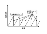
- FIG. 1 conceptually shows the relationship between the thickness of the generated film and the residual stress (internal stress).
- the film thickness increases with time, and the residual stress also increases accordingly.
- the residual stress exceeds the peeling limit line, the produced film is peeled off, so that the film forming process by cold spray is temporarily stopped before that.
- “heat treatment” is separately performed on the deposition target. By this heat treatment, the residual stress of the generated film is removed. Thereafter, the film formation process by cold spray starts again.
- the unit film forming process includes (1) a process of forming a film by cold spray so that the residual stress does not exceed the peeling limit line, and (2) a process of performing a heat treatment to remove the residual stress. .
- Patent Document 2 discloses a method of forming a film having a thickness of about 400 ⁇ m by a cold spray method.
- the method includes (A) a step of reducing or removing oxide on the surface of the film raw material powder on which the oxide is formed on the surface of the metal powder by hydrogen reduction treatment or pickling treatment, and (B) the oxide.
- Patent Document 3 discloses a method of forming a film of about 1.5 mm by a cold spray method.
- the method includes a step of projecting non-spherical irregularly shaped particles made of metal onto the substrate surface by a cold spray method to form a metal film on the substrate surface.
- the inventors of the present application focused on the following points. As described above, in order to realize a thick film using the cold spray method, it is necessary to perform a heat treatment during the film formation. However, as the number of heat treatments increases, the film formation time as a whole also increases. This is not only because the heat treatment itself requires a certain amount of time, but also because it is necessary to stop and restart the cold spray device every time the heat treatment is performed and restart and adjust the cold spray device every time the film forming process is restarted. That is, as the number of heat treatments increases, the film formation cost increases. Therefore, the smaller the number of heat treatments (unit film formation treatment), the better.
- One object of the present invention is to provide a technique capable of reducing the number of heat treatments (unit film forming processes) in thickening using a cold spray.
- a film forming method includes a step of repeatedly executing the unit film forming process until the thickness of the film formed on the film formation target reaches a desired film thickness.
- the unit film forming process includes (A) a step of forming a film on the film formation target by a cold spray method while heating the film formation target with a heater, and (B) a process on the film formation target after film formation. Applying heat treatment.
- a film forming method in another aspect of the present invention, includes a step of forming a film with a thickness of 1 mm or more on the film formation target by forming a film on the film formation target by a cold spray method while heating the film formation target with a heater. .
- the present invention it is possible to reduce the number of heat treatments (unit film forming processes) in thickening using cold spray. As a result, the film formation cost is reduced.
- FIG. 1 is a diagram conceptually showing the relationship between the thickness of a generated film and the residual stress (internal stress) when forming a thick film by cold spray.
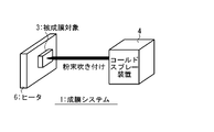
- FIG. 2 is a schematic diagram showing the configuration of the film forming system according to the first embodiment of the present invention.
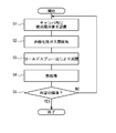
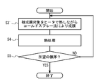
- FIG. 3 is a flowchart showing a film forming method according to the first embodiment of the present invention.
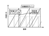
- FIG. 4 is a conceptual diagram for explaining the effect of the first embodiment of the present invention.
- FIG. 5 is a flowchart showing a film forming method according to the second embodiment of the present invention.
- FIG. 6 is a schematic diagram showing a configuration of a film forming system according to the third embodiment of the present invention.
- FIG. 1 is a diagram conceptually showing the relationship between the thickness of a generated film and the residual stress (internal stress) when forming a thick film by cold spray.
- FIG. 2 is a schematic diagram showing the configuration of the film forming system according to the first embodiment of the present invention.
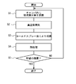
- FIG. 7 is a flowchart showing a film forming method according to the third embodiment of the present invention.
- FIG. 8 is a conceptual diagram for explaining the effect of the third embodiment of the present invention.
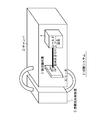
- FIG. 9 is a schematic diagram showing the configuration of a film forming system according to the fourth embodiment of the present invention.
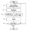
- FIG. 10 is a flowchart showing a film forming method according to the fourth embodiment of the present invention.
- FIG. 11 is a schematic cross-sectional view showing the configuration of the combustion chamber of the rocket engine in the fifth embodiment of the present invention.
- FIG. 12 is a schematic diagram showing the configuration of the combustion chamber of the rocket engine in the fifth embodiment of the present invention.
- FIG. 2 schematically shows a configuration of a film forming system 1 according to a first embodiment.
- the film forming system 1 includes a chamber 2, a cold spray device 4, and an atmosphere control device 5.
- a deposition target 3 is installed in the chamber 2 (deposition chamber).
- the cold spray device 4 is installed so that the film formation target 3 can be formed by a cold spray method.
- the atmosphere control device 5 is provided to control the atmosphere in the chamber 2.
- the atmosphere control device 5 is a gas supply device that supplies “non-oxidizing gas” to the chamber 2.
- the non-oxidizing gas include rare gases such as Ar and He, N 2 and the like.
- FIG. 3 is a flowchart showing the film forming method according to the first embodiment. With reference to FIG.2 and FIG.3, the film-forming method based on 1st Embodiment is demonstrated.
- Step S1 First, the deposition target 3 is installed in the chamber 2.
- Step S2 Subsequently, the atmosphere control device 5 operates to supply a non-oxidizing gas into the chamber 2. As a result, the atmosphere in the chamber 2 is set to a non-oxidizing gas atmosphere.
- the non-oxidizing gas include rare gases such as Ar and He, N 2 and the like.
- Step S3 Next, the cold spray device 4 is operated to form a film on the film formation target 3 by the cold spray method.
- the film forming process is performed in the non-oxidizing gas atmosphere set in step S2. Therefore, oxidation during the film forming process is prevented.
- a metal film is typically formed by spraying metal material powder.
- an example of cold spray conditions when forming a copper film by spraying copper powder is as follows.
- Cold spray working gas helium, nitrogen Copper powder supply: 20g / min-300g / min
- Gas pressure 2MPa-10MPa Powder and gas temperature in heating furnace before film formation: 200 ° C-950 ° C
- Step S4 When one film formation process is completed, the film formation target 3 after film formation is taken out of the chamber 2 and placed in a heat treatment apparatus (not shown). Then, heat treatment is performed on the deposition target 3. As a result, the residual stress of the generated film is removed.
- Step S5 Steps S1 to S4 described above are “unit film forming processes”.
- the unit film forming process is completed once, if the generated film thickness does not reach the desired film thickness (step S5; No), the process returns to step S1.
- the process ends. That is, the unit film formation process is repeatedly performed until the thickness of the film formed on the film formation target 3 reaches a desired film thickness.
- the desired film thickness is typically 1 mm or more.
- the desired film thickness is typically 10 mm or more. Even such a thick film can be formed using a cold spray method by performing a heat treatment to remove residual stress.
- the film formation process by cold spray is performed in a non-oxidizing gas atmosphere.
- a comparative example let us consider performing a film forming process by cold spray in the atmosphere as in the past.
- the oxide formed in the middle of the film forming process became obvious by the heat treatment, and cracks were generated in the generated film. Such cracks in the generated film reduce the adhesion of the generated film.
- the film forming process is performed in a non-oxidizing gas atmosphere, oxidation during the film forming process is prevented. As a result, generation of cracks in the generated film is prevented. This has been confirmed through experiments by the present inventors.
- the prevention of cracks means that the generated film becomes dense and the adhesion of the generated film increases. Since the peeling limit line is determined from the adhesion force and residual stress of the generated film, the peeling limit line increases as the adhesion force increases.
- the film thickness that can be formed by one unit film forming process increases. Accordingly, the number of repetitions of the unit film forming process necessary for obtaining a desired film thickness is reduced. That is, the number of heat treatments to be performed is reduced. As a result, the film formation cost is reduced.
- the present embodiment capable of suppressing the generation of cracks is suitable for increasing the thickness of the metal film of the structure.
- the atmosphere in the chamber 2 is set to a non-oxidizing gas atmosphere.
- the atmosphere is not limited thereto.
- a vacuum atmosphere is used instead of the non-oxidizing gas atmosphere.
- the atmosphere control device 5 is a decompression device that puts the chamber 2 in a vacuum state.
- the vacuum is in a state where the pressure is 1 ⁇ 10 ⁇ 3 Pa or less.
- FIG. 5 is a flowchart showing a film forming method according to the second embodiment.
- step S2 ' is executed instead of step S2 described above.
- the atmosphere control device 5 is activated to set the atmosphere in the chamber 2 to a vacuum atmosphere. Others are the same as those in the first embodiment.
- FIG. 6 schematically shows a configuration of a film forming system 1 according to a third embodiment.
- the film forming system 1 includes a cold spray device 4 and a heater 6.
- the heater 6 is provided so as to heat the film formation target 3, and is typically provided so as to contact the film formation target 3.
- the cold spray device 4 is installed so that the film formation target 3 can be formed by a cold spray method.
- FIG. 7 is a flowchart showing a film forming method according to the first embodiment.
- the film-forming method which concerns on 3rd Embodiment is demonstrated.
- the description which overlaps with 1st Embodiment is abbreviate
- Step S3 ′ The heater 6 operates to heat the film formation target 3. As a result, the temperature of the deposition target 3 becomes higher than room temperature.
- the cold spray device 4 is operated to form a film on the film formation target 3 by the cold spray method. That is, film formation is performed on the film formation target 3 while the film formation target 3 is heated by the heater 6.
- the cold spray conditions are the same as in the first embodiment.
- Step S4 When one film formation process is completed, a heat treatment is performed on the film formation target 3 as in the case of the first embodiment. As a result, the residual stress of the generated film is removed.
- Step S5 Steps S3 ′ to S4 described above are “unit film forming processes”.
- the process returns to step S3 ′.
- the process ends. That is, the unit film formation process is repeatedly performed until the thickness of the film formed on the film formation target 3 reaches a desired film thickness.
- the desired film thickness is typically 1 mm or more.
- the desired film thickness is typically 10 mm or more. Even such a thick film can be formed using a cold spray method by performing a heat treatment to remove residual stress.
- the film forming process by cold spray is performed while the film formation target 3 is heated by the heater 6. The effect of this will be described with reference to FIG.
- the cold spray method is a method of forming a film by colliding a material powder with an exposed surface. Due to such properties, as the film forming process is repeated, the exposed surface is heated more and more (the surface temperature reaches about 200 ° C.). That is, as the film thickness increases, a new film is formed in a heated state. Conversely, in the initial stage of film formation, a new film is formed at about room temperature.
- the inventor of the present application considered that such a temperature difference during film formation affects the adhesion of the generated film. That is, on the side closest to the film formation target 3, since the temperature at the time of film formation is substantially room temperature, it was considered that the adhesion of the generated film is weak and peeling is likely to occur.
- the deposition target 3 is “positively” heated by using the heater 6, and the temperature is set higher than the room temperature.
- the heating temperature is set to about 200 ° C., which is the temperature at which the surface temperature is reached by cold spray, for example.
- the adhesion of the generated film increases, and thereby the peeling limit line also increases. Therefore, as in the case of the first embodiment, the number of repetitions of the unit film forming process necessary for obtaining a desired film thickness is reduced (see FIG. 4). That is, the number of heat treatments to be performed is reduced. As a result, the film formation cost is reduced.
- the fourth embodiment is a combination of the first or second embodiment and the third embodiment.
- FIG. 9 schematically shows a configuration of a film forming system 1 according to the fourth embodiment.
- the film forming system 1 includes a heater 6 shown in FIG. 6 in addition to the configuration shown in FIG.
- FIG. 10 is a flowchart showing a film forming method according to the fourth embodiment.
- step S3 is replaced with step S3 'in the third embodiment.
- the effect of the combination of the first or second embodiment and the third embodiment can be obtained.
- a further increase in the adhesion of the resulting film is expected and suitable.
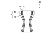
- FIG. 11 schematically shows the combustion chamber 25 of the rocket engine.
- a high-temperature and high-pressure fluid burns and circulates during use.
- the combustion chamber 25 has a plurality of cooling channels 14 through which the refrigerant passes, and the temperature of the combustion chamber 25 can be suppressed by cooling with the refrigerant.
- the combustion chamber 25 includes an inner cylinder 10 and an outer cylinder 15 arranged concentrically, and a cooling channel 14 is formed between the inner cylinder 10 and the outer cylinder 15. .
- copper or an alloy containing copper as a main component is preferable in terms of cooling efficiency, strength, and extension.
- FIG. 12 shows the relationship between the inner cylinder 10, the cooling flow path 14, and the outer cylinder 15.
- a plurality of cooling channels 14 are formed in the inner cylinder 10.
- An outer cylinder 15 is formed on the inner cylinder 10 as a base material. More specifically, the outer cylinder 15 has a laminated structure of the first layer 12 and the second layer 13. The first layer 12 is formed in layers on the inner cylinder 10 on the inner cylinder 10 side. The second layer 13 is formed in a layered manner on the outer surface of the first layer 12.
- the manufacturing method of the “structure” as shown in FIG. 12 is as follows. First, a plurality of grooves are formed on the surface of the inner cylinder 10 as the base material portion. The groove finally becomes the fluid flow path 14. Subsequently, a plurality of grooves are filled with a filler such as wax. Here, the filler is filled so that the exposed surface and the surface (exposed surface) of the base material portion form substantially the same plane.
- a conductive layer such as silver powder is formed on the exposed surface of the filler and the inner cylinder 10 (base material portion). That is, in the electroforming method, a conductive process is performed on a region where an electroformed film is formed. And the 1st layer 12 is formed as an electroforming film
- the second layer 13 is formed as a cold spray film on the first layer 12 by the method described in the above embodiment.
- a cold spray film of copper is laminated about 10 mm.
- the total thickness of the first layer 12 and the second layer 13 is set to a desired thickness for the outer cylinder 15.
- the filler is removed from the plurality of grooves by a method such as melting. Thereby, a structure having a plurality of cooling channels 14 surrounded by the outer cylinder 15 and the inner cylinder 10 can be manufactured.
- the outer cylinder 15 is formed by combining the electroforming method and the cold spray method.
- the film formation rate of the cold spray method is extremely high as compared with the film formation rate of the electroforming method. Therefore, the case where the film of the outer cylinder 15 (eg, copper film) is formed by combining the electroforming method and the cold spray method is much shorter than the case where the film is formed only by the electroforming method. The film formation can be terminated. Thereby, the manufacturing time of the structure can be shortened while maintaining the mechanical properties such as the strength and elongation of the film.
- the first layer 12 is formed by electroforming and the second layer 13 is formed by cold spraying, it is preferable that the first layer 12 is relatively thin and the second layer 13 is relatively thick. . As a result, it is possible to shorten the manufacturing period, reduce manufacturing costs, and manufacturing labor.
Landscapes
- Chemical & Material Sciences (AREA)
- Engineering & Computer Science (AREA)
- Chemical Kinetics & Catalysis (AREA)
- Materials Engineering (AREA)
- Mechanical Engineering (AREA)
- Metallurgy (AREA)
- Organic Chemistry (AREA)
- Physics & Mathematics (AREA)
- Plasma & Fusion (AREA)
- Other Surface Treatments For Metallic Materials (AREA)
Abstract
成膜方法は、被成膜対象上に形成される膜の厚さが所望の膜厚になるまで、単位成膜処理を繰り返し実行するステップを有する。単位成膜処理は、(A)被成膜対象をヒータで熱しながら、コールドスプレー法により被成膜対象に対して成膜を行うステップと、(B)成膜後の被成膜対象に対して熱処理を施すステップと、を含む。
Description
本発明は、コールドスプレーを利用した成膜技術に関する。
構造体を製造するために、基材上に厚膜を形成する必要がある場合がある。例えば、そのような構造体として、航空宇宙用のロケットエンジンの燃焼室が挙げられる。ロケットエンジンの燃焼室を製造する場合、例えば、銅基材上に10mm以上の銅膜を形成する必要がある。
そのような金属厚膜を形成するための一手法として、「電鋳法」が挙げられる。しかしながら、電鋳法による膜成長速度は極めて遅く、例えば10mm程度の目標膜厚を達成するためには数ヶ月を要する。
このような問題を解決するため、本願出願人は、特許文献1において、「コールドスプレー法」を利用することにより金属厚膜を成膜する技術を提案している。コールドスプレー法は、材料粉末の融点または軟化温度よりも低い温度のガスを高速流にし、そのガス流中に材料粒子を投入し加速させ、固相状態のまま基材に衝突させて皮膜を形成する方法である。このコールドスプレー法による成膜速度は、電鋳法の場合と比較して極めて速い。従って、コールドスプレー法を利用することにより、構造体の製造に要する期間を大幅に短縮することが可能となる。
但し、コールドスプレーで薄い酸化被膜等を成膜するような場合とは異なり、コールドスプレーで10mm程度の厚膜を成膜する場合には、次の点に留意する必要がある。それは、生成膜の膜厚がある程度に達した段階で、残留応力が密着力よりも強くなり、生成膜の剥離が発生してしまうということである。そのような生成膜の剥離が発生する限界は、以下、「剥離限界」と参照される。生成膜の剥離を防止するためには、特許文献1に記載の通り、剥離限界の前に、熱処理を行って残留応力を除去する必要がある。
図1は、生成膜の膜厚と残留応力(内部応力)との関係を概念的に示している。図1に示されるように、コールドスプレーにより成膜を行うと、膜厚が時間的に増加していくが、それに伴い、残留応力も増加していく。残留応力が剥離限界ラインを超えると生成膜が剥離してしまうため、その前に、コールドスプレーによる成膜処理が一旦止められる。そして、被成膜対象に対して別途、「熱処理」が実施される。この熱処理により、生成膜の残留応力が除去される。その後、コールドスプレーによる成膜処理が再度開始する。
このように、コールドスプレーによって10mm程度の厚膜を形成するためには、成膜処理と熱処理を繰り返し実施する必要がある。繰り返しの単位となる処理は、以下、「単位成膜処理」と参照される。単位成膜処理は、(1)残留応力が剥離限界ラインを超えないように、コールドスプレーにより成膜する工程と、(2)その残留応力を除去するために熱処理を実施する工程と、を含む。
コールドスプレーに関連する他の技術として、次のものが知られている。
特許文献2は、400μm程度の皮膜をコールドスプレー法により成膜する方法を開示している。当該方法は、(A)金属粉末の表面に酸化物が形成されている皮膜原料粉末の表面の酸化物を水素還元処理または酸洗処理によって減少させるまたは除去する工程と、(B)酸化物を減少させたまたは除去した皮膜原料粉末を、コールドスプレー法によって、被覆対象物に衝突させて皮膜を形成する工程と、を含む。
特許文献3は、1.5mm程度の皮膜をコールドスプレー法により成膜する方法を開示している。当該方法は、基材表面に、コールドスプレー法により金属からなる非球状の異形粒子を投射し、基材表面に金属皮膜を形成する工程を含む。
本願発明者は、次の点に着目した。上述の通り、コールドスプレー法を用いて厚膜化を実現するためには、成膜途中に熱処理を実施する必要がある。しかしながら、熱処理の回数が増加するにつれ、全体としての成膜時間も増大してしまう。それは、熱処理そのものがある程度の時間を要するからだけでなく、熱処理の度にコールドスプレー装置を停止し、成膜処理を再開する度にコールドスプレー装置を再度起動及び調整する必要があるからである。すなわち、熱処理の回数が増加するにつれ、成膜コストが増大してしまう。よって、熱処理(単位成膜処理)の回数は少なければ少ないほどよい。
本発明の1つの目的は、コールドスプレーを利用した厚膜化において、熱処理(単位成膜処理)の回数を低減することができる技術を提供することにある。
本発明の1つの観点において、成膜方法が提供される。その成膜方法は、被成膜対象上に形成される膜の厚さが所望の膜厚になるまで、単位成膜処理を繰り返し実行するステップを有する。単位成膜処理は、(A)被成膜対象をヒータで熱しながら、コールドスプレー法により被成膜対象に対して成膜を行うステップと、(B)成膜後の被成膜対象に対して熱処理を施すステップと、を含む。
本発明の他の観点において、成膜方法が提供される。その成膜方法は、被成膜対象をヒータで熱しながら、コールドスプレー法により被成膜対象に対して成膜を行い、被成膜対象上に膜厚1mm以上の膜を形成するステップを含む。
本発明によれば、コールドスプレーを利用した厚膜化において、熱処理(単位成膜処理)の回数を低減することが可能となる。その結果、成膜コストが削減される。
添付図面を参照して、本発明の実施の形態に係る成膜技術を説明する。
1.第1の実施の形態
図2は、第1の実施の形態に係る成膜システム1の構成を概略的に示している。成膜システム1は、チャンバ2、コールドスプレー装置4、及び雰囲気制御装置5を備えている。チャンバ2(成膜室)内には、被成膜対象3が設置される。コールドスプレー装置4は、その被成膜対象3に対してコールドスプレー法によって成膜を行うことができるように設置されている。
図2は、第1の実施の形態に係る成膜システム1の構成を概略的に示している。成膜システム1は、チャンバ2、コールドスプレー装置4、及び雰囲気制御装置5を備えている。チャンバ2(成膜室)内には、被成膜対象3が設置される。コールドスプレー装置4は、その被成膜対象3に対してコールドスプレー法によって成膜を行うことができるように設置されている。
雰囲気制御装置5は、チャンバ2内の雰囲気を制御するために設けられている。第1の実施の形態では、雰囲気制御装置5は、チャンバ2に「非酸化性ガス」を供給するガス供給装置である。非酸化性ガスとしては、ArやHeといった希ガスやN2などが例示される。
図3は、第1の実施の形態に係る成膜方法を示すフローチャートである。図2及び図3を参照して、第1の実施の形態に係る成膜方法を説明する。
ステップS1:
まず、チャンバ2内に被成膜対象3が設置される。
まず、チャンバ2内に被成膜対象3が設置される。
ステップS2:
続いて、雰囲気制御装置5が作動し、チャンバ2内に非酸化性ガスを供給する。その結果、チャンバ2内の雰囲気は非酸化性ガス雰囲気に設定される。非酸化性ガスとしては、ArやHeといった希ガスやN2などが例示される。
続いて、雰囲気制御装置5が作動し、チャンバ2内に非酸化性ガスを供給する。その結果、チャンバ2内の雰囲気は非酸化性ガス雰囲気に設定される。非酸化性ガスとしては、ArやHeといった希ガスやN2などが例示される。
ステップS3:
次に、コールドスプレー装置4が作動し、被成膜対象3に対してコールドスプレー法により成膜を行う。ここで、その成膜処理は、上記ステップS2で設定された非酸化性ガス雰囲気中で行われることに留意されたい。従って、成膜処理途中における酸化が防止される。
次に、コールドスプレー装置4が作動し、被成膜対象3に対してコールドスプレー法により成膜を行う。ここで、その成膜処理は、上記ステップS2で設定された非酸化性ガス雰囲気中で行われることに留意されたい。従って、成膜処理途中における酸化が防止される。
コールドスプレー法では、被成膜対象3の表面に材料粉末を吹き付けることにより、成膜が行われる。ロケットエンジンの燃焼室といった構造体を製造する場合、典型的には、金属材料粉末の吹き付けにより金属膜の成膜が行われる。例えば、銅粉末の吹き付けにより銅膜を形成する場合のコールドスプレー条件の一例は、次の通りである。
コールドスプレーの作動ガス:ヘリウム、窒素
銅粉末供給量:20g/min-300g/min
ガス圧力:2MPa-10MPa
成膜前加熱炉内の粉末及びガス温度:200℃-950℃
銅粉末供給量:20g/min-300g/min
ガス圧力:2MPa-10MPa
成膜前加熱炉内の粉末及びガス温度:200℃-950℃
また、生成膜厚が大きくなるにつれ、生成膜の残留応力も大きくなる。そのような残留応力による生成膜の剥離が発生しないように、コールドスプレーによる1回の成膜処理は、生成膜厚が剥離限界膜厚を超える前に止められる。そして、生成膜の残留応力を除去するために、次に説明されるように熱処理が実施される。
ステップS4:
1回の成膜処理が完了すると、成膜後の被成膜対象3はチャンバ2から取り出され、熱処理装置(図示されない)に設置される。そして、その被成膜対象3に対して熱処理が実施される。その結果、生成膜の残留応力が除去される。
1回の成膜処理が完了すると、成膜後の被成膜対象3はチャンバ2から取り出され、熱処理装置(図示されない)に設置される。そして、その被成膜対象3に対して熱処理が実施される。その結果、生成膜の残留応力が除去される。
ステップS5:
以上に説明されたステップS1~S4が、「単位成膜処理」である。1回の単位成膜処理が完了した際、生成膜厚が所望の膜厚に達していない場合(ステップS5;No)、処理はステップS1に戻る。一方、生成膜厚が所望の膜厚に達した場合(ステップS5;Yes)、処理は終了する。すなわち、被成膜対象3上に形成される膜の厚さが所望の膜厚になるまで、単位成膜処理が繰り返し実行される。
以上に説明されたステップS1~S4が、「単位成膜処理」である。1回の単位成膜処理が完了した際、生成膜厚が所望の膜厚に達していない場合(ステップS5;No)、処理はステップS1に戻る。一方、生成膜厚が所望の膜厚に達した場合(ステップS5;Yes)、処理は終了する。すなわち、被成膜対象3上に形成される膜の厚さが所望の膜厚になるまで、単位成膜処理が繰り返し実行される。
単なる皮膜ではなく構造体の製造を念頭においた場合、所望の膜厚は、典型的には1mm以上である。ロケットエンジンの燃焼室の製造の場合、所望の膜厚は、典型的には10mm以上である。このような厚膜であっても、熱処理を実施して残留応力を除去することにより、コールドスプレー法を利用した成膜が可能である。
以上に説明されたように、本実施の形態によれば、コールドスプレーによる成膜処理は、非酸化性ガス雰囲気中で行われる。比較例として、従来のように大気中でコールドスプレーによる成膜処理を行うことを考える。そのような比較例の場合、成膜処理途中に形成された酸化物が熱処理によって顕在化し、生成膜中にクラックが発生することが観測された。そのような生成膜中のクラックは、生成膜の密着力を低下させる。
一方、本実施の形態によれば、成膜処理は非酸化性ガス雰囲気中で行われるため、成膜処理途中の酸化は防止される。その結果、生成膜中のクラックの発生が防止される。このことは、本願発明者による実験を通しても確認されている。クラックの発生が防止されるということは、生成膜が緻密となり、生成膜の密着力が増加することを意味する。剥離限界ラインは生成膜の密着力と残留応力から決まるため、密着力が増加すると、剥離限界ラインも上昇する。
剥離限界ラインが上昇すると、図4に示されるように、1回の単位成膜処理で形成可能な膜厚が増加する。従って、所望の膜厚を得るために必要な単位成膜処理の繰り返し回数が減少する。すなわち、実施すべき熱処理の回数が低減される。その結果、成膜コストが削減される。
所望の膜厚が大きくなるにつれ、単位成膜処理の繰り返し回数は増える傾向にある。よって、所望の膜厚が大きくなるにつれ、本実施の形態を適用することがより好ましくなると言える。
また、例えばロケットエンジンの燃焼室といった構造体の場合、クラックの発生は、信頼性の観点から問題となる。その点、クラックの発生を抑制することができる本実施の形態は、構造体の金属膜の厚膜化に好適である。
2.第2の実施の形態
上述の第1の実施の形態では、チャンバ2内の雰囲気は非酸化性ガス雰囲気に設定された。しかし、酸化が抑制されるのであれば、雰囲気はそれに限られない。第2の実施の形態では、非酸化性ガス雰囲気の代わりに、真空雰囲気が用いられる。その場合、雰囲気制御装置5は、チャンバ2を真空状態にする減圧装置である。真空は、例えば、圧力が1×10⁻³Pa以下の状態である。
上述の第1の実施の形態では、チャンバ2内の雰囲気は非酸化性ガス雰囲気に設定された。しかし、酸化が抑制されるのであれば、雰囲気はそれに限られない。第2の実施の形態では、非酸化性ガス雰囲気の代わりに、真空雰囲気が用いられる。その場合、雰囲気制御装置5は、チャンバ2を真空状態にする減圧装置である。真空は、例えば、圧力が1×10⁻³Pa以下の状態である。
図5は、第2の実施の形態に係る成膜方法を示すフローチャートである。第2の実施の形態では、上述のステップS2の代わりに、ステップS2’が実行される。ステップS2’において、雰囲気制御装置5が作動し、チャンバ2内の雰囲気を真空雰囲気に設定する。その他は、第1の実施の形態と同じである。
第2の実施の形態によれば、第1の実施の形態と同じ効果が得られる。
3.第3の実施の形態
図6は、第3の実施の形態に係る成膜システム1の構成を概略的に示している。成膜システム1は、コールドスプレー装置4とヒータ6を備えている。ヒータ6は、被成膜対象3を熱することができるように設けられており、典型的には、被成膜対象3に接触するように設けられている。コールドスプレー装置4は、その被成膜対象3に対してコールドスプレー法によって成膜を行うことができるように設置されている。
図6は、第3の実施の形態に係る成膜システム1の構成を概略的に示している。成膜システム1は、コールドスプレー装置4とヒータ6を備えている。ヒータ6は、被成膜対象3を熱することができるように設けられており、典型的には、被成膜対象3に接触するように設けられている。コールドスプレー装置4は、その被成膜対象3に対してコールドスプレー法によって成膜を行うことができるように設置されている。
図7は、第1の実施の形態に係る成膜方法を示すフローチャートである。図6及び図7を参照して、第3の実施の形態に係る成膜方法を説明する。尚、第1の実施の形態と重複する説明は、適宜省略される。
ステップS3’:
ヒータ6が作動し、被成膜対象3を熱する。その結果、被成膜対象3の温度は、室温よりも高くなる。そして、この状態で、コールドスプレー装置4が作動し、被成膜対象3に対してコールドスプレー法により成膜を行う。つまり、被成膜対象3がヒータ6で熱せられながら、被成膜対象3に対して成膜が行われる。コールドスプレー条件は、第1の実施の形態の場合と同様である。
ヒータ6が作動し、被成膜対象3を熱する。その結果、被成膜対象3の温度は、室温よりも高くなる。そして、この状態で、コールドスプレー装置4が作動し、被成膜対象3に対してコールドスプレー法により成膜を行う。つまり、被成膜対象3がヒータ6で熱せられながら、被成膜対象3に対して成膜が行われる。コールドスプレー条件は、第1の実施の形態の場合と同様である。
ステップS4:
1回の成膜処理が完了すると、第1の実施の形態の場合と同様に、被成膜対象3に対して熱処理が実施される。その結果、生成膜の残留応力が除去される。
1回の成膜処理が完了すると、第1の実施の形態の場合と同様に、被成膜対象3に対して熱処理が実施される。その結果、生成膜の残留応力が除去される。
ステップS5:
以上に説明されたステップS3’~S4が、「単位成膜処理」である。1回の単位成膜処理が完了した際、生成膜厚が所望の膜厚に達していない場合(ステップS5;No)、処理はステップS3’に戻る。一方、生成膜厚が所望の膜厚に達した場合(ステップS5;Yes)、処理は終了する。すなわち、被成膜対象3上に形成される膜の厚さが所望の膜厚になるまで、単位成膜処理が繰り返し実行される。
以上に説明されたステップS3’~S4が、「単位成膜処理」である。1回の単位成膜処理が完了した際、生成膜厚が所望の膜厚に達していない場合(ステップS5;No)、処理はステップS3’に戻る。一方、生成膜厚が所望の膜厚に達した場合(ステップS5;Yes)、処理は終了する。すなわち、被成膜対象3上に形成される膜の厚さが所望の膜厚になるまで、単位成膜処理が繰り返し実行される。
単なる皮膜ではなく構造体の製造を念頭においた場合、所望の膜厚は、典型的には1mm以上である。ロケットエンジンの燃焼室の製造の場合、所望の膜厚は、典型的には10mm以上である。このような厚膜であっても、熱処理を実施して残留応力を除去することにより、コールドスプレー法を利用した成膜が可能である。
以上に説明されたように、本実施の形態によれば、コールドスプレーによる成膜処理は、被成膜対象3をヒータ6で熱しつつ行われる。これによる効果を、図8を参照して説明する。
比較例として、従来のように室温でコールドスプレーによる成膜処理を行うことを考える。そのような比較例の場合、被成膜対象3と生成膜との界面において剥離が発生することがしばしば観測された。つまり、多くの場合、生成膜は、最も被成膜対象3に近い側から剥離することが観測された。その原因について、本願発明者は次のように考えた。
コールドスプレー法は、材料粉末を露出表面に衝突させて成膜を行う方法である。そのような性質上、成膜処理が繰り返されるにつれ、どんどん露出表面が加熱される(表面温度は、200℃程度にまで達する)。つまり、膜厚が大きくなればなるほど、加熱された状態で新たな膜が形成されることになる。逆に、成膜の初期段階では、ほぼ室温で新たな膜が形成される。本願発明者は、このような膜形成時の温度差が生成膜の密着力に影響を与えると考えた。つまり、最も被成膜対象3に近い側では、成膜時の温度がほぼ室温であるため、生成膜の密着力が弱く、剥離が発生しやすくなると考えた。
そこで、本実施の形態では、ヒータ6を用いることにより被成膜対象3が“積極的”に加熱され、その温度が室温よりも高く設定される。その加熱温度は、例えば、コールドスプレーによって表面温度が達する温度である200℃程度に設定される。これにより、成膜の初期段階であっても、成膜面は十分熱くなる。このことが、原子の拡散を促し、生成膜の密着力を向上させると考えられる。実際に、図8に示されるように、本実施の形態の方法によって剥離限界膜厚が格段に増加することが、本願発明者が行った実験により確認されている。
このように、本実施の形態によれば、生成膜の密着力が増加し、それにより、剥離限界ラインも上昇する。従って、第1の実施の形態の場合と同様に、所望の膜厚を得るために必要な単位成膜処理の繰り返し回数が減少する(図4参照)。すなわち、実施すべき熱処理の回数が低減される。その結果、成膜コストが削減される。
所望の膜厚が大きくなるにつれ、単位成膜処理の繰り返し回数は増える傾向にある。よって、所望の膜厚が大きくなるにつれ、本実施の形態を適用することがより好ましくなると言える。
4.第4の実施の形態
第4の実施の形態は、第1あるいは第2の実施の形態と第3の実施の形態の組み合わせである。
第4の実施の形態は、第1あるいは第2の実施の形態と第3の実施の形態の組み合わせである。
図9は、第4の実施の形態に係る成膜システム1の構成を概略的に示している。成膜システム1は、既出の図2で示された構成に加えて、図6で示されたヒータ6を備えている。
図10は、第4の実施の形態に係る成膜方法を示すフローチャートである。図3(第1の実施の形態)あるいは図5(第2の実施の形態)で示された成膜方法において、ステップS3が、第3の実施の形態のステップS3’で置換されている。
第4の実施の形態によれば、第1あるいは第2の実施の形態と第3の実施の形態の組み合わせの効果が得られる。生成膜の密着力の更なる増加が期待され、好適である。
5.第5の実施の形態
一例として、上述の実施の形態に係る成膜方法を、ロケットエンジンの燃焼室の製造に適用する場合を考える。尚、本願出願人による先願(特開2012-57203号公報)も参照されたい。
一例として、上述の実施の形態に係る成膜方法を、ロケットエンジンの燃焼室の製造に適用する場合を考える。尚、本願出願人による先願(特開2012-57203号公報)も参照されたい。
図11は、ロケットエンジンの燃焼室25を概略的に示している。この燃焼室25では、使用時に高温高圧の流体が燃焼し流通する。また、燃焼室25は、冷媒が通過する複数の冷却流路14を有しており、その冷媒による冷却により燃焼室25の温度を抑制することができる。より詳細には、燃焼室25は、同心円状に配置された内筒10と外筒15とを備えており、それら内筒10と外筒15との間に冷却流路14が形成されている。尚、内筒10及び外筒15の材料としては、冷却効率や強度や延びの面から銅又は銅を主成分とする合金が好ましい。
図12は、内筒10、冷却流路14及び外筒15の関係を示している。内筒10には、複数の冷却流路14が形成されている。この内筒10を基材として、その上に外筒15が形成されている。より詳細には、外筒15は、第1層12と第2層13の積層構造を有している。第1層12は、内筒10側に、内筒10上に層状に形成されている。第2層13は、第1層12の外側の表面に層状に形成されている。
図12で示されたような「構造体」の製造方法は、次の通りである。まず、基材部としての内筒10の表面に複数の溝が形成される。その溝は、最終的に流体流路14となるものである。続いて、ワックスのような充填剤が複数の溝に充填される。ここで、充填剤は、その露出面と基材部の表面(露出面)とが概ね同一の平面を成すように充填される。
次に、充填剤及び内筒10(基材部)の露出面に銀粉のような導電層が形成される。すなわち、電鋳法において、電鋳皮膜を形成する領域に導電処理を施す。そして、電鋳法により、導電処理を施された充填剤及び内筒10の表面に、電鋳皮膜として第1層12が形成される。
次に、上述の実施の形態で説明された方法により、第1層12上に、コールドスプレー膜として第2層13が形成される。例えば、銅のコールドスプレー膜を10mm程度積層する。この第1層12と第2層13とを合わせた膜厚が、外筒15として所望の膜厚となるようにする。
その後、複数の溝から充填剤を溶融等の方法により除去する。それにより、外筒15と内筒10とで囲まれた複数の冷却流路14を有する構造体を製造することができる。
このように、本実施の形態では、電鋳法とコールドスプレー法を組み合わせて外筒15を成膜している。ここで、コールドスプレー法の成膜速度は電鋳法の成膜速度と比較して極めて速い。そのため、電鋳法とコールドスプレー法を組み合わせて外筒15の膜(例:銅膜)を成膜する場合の方が、電鋳法だけで成膜する場合と比較して、極めて短期間に成膜を終了させることができる。それにより、膜の強度や延びなどの力学的特性を維持しながら、構造体の製造期間を短縮できる。
また、第1層12を電鋳法で、第2層13をコールドスプレー法でそれぞれ形成する場合、第1層12を相対的に薄くし、第2層13を相対的に厚くすることが好ましい。それにより、製造期間の短縮や製造コストや製造の手間の削減を図ることができる。
以上、本発明の実施の形態が添付の図面を参照することにより説明された。但し、本発明は、上述の実施の形態に限定されず、要旨を逸脱しない範囲で当業者により適宜変更され得る。
本出願は、2013年2月19日に出願された日本国特許出願2013-030404を基礎とする優先権を主張し、その開示の全てをここに取り込む。
Claims (6)
- 被成膜対象上に形成される膜の厚さが所望の膜厚になるまで、単位成膜処理を繰り返し実行するステップを有し、
前記単位成膜処理は、
前記被成膜対象をヒータで熱しながら、コールドスプレー法により前記被成膜対象に対して成膜を行うステップと、
前記成膜後の前記被成膜対象に対して熱処理を施すステップと
を含む
成膜方法。 - 請求項1に記載の成膜方法であって、
前記コールドスプレー法により金属膜の成膜が行われる
成膜方法。 - 請求項1又は2に記載の成膜方法であって、
前記所望の膜厚は1mm以上である
成膜方法。 - 請求項1又は2に記載の成膜方法であって、
前記所望の膜厚は10mm以上である
成膜方法。 - 被成膜対象をヒータで熱しながら、コールドスプレー法により前記被成膜対象に対して成膜を行い、前記被成膜対象上に膜厚1mm以上の膜を形成するステップを含む
成膜方法。 - 請求項5に記載の成膜方法であって、
前記コールドスプレー法により金属膜の成膜が行われる
成膜方法。
Priority Applications (1)
| Application Number | Priority Date | Filing Date | Title |
|---|---|---|---|
| US14/764,766 US9951426B2 (en) | 2013-02-19 | 2013-05-20 | Method for depositing layer |
Applications Claiming Priority (2)
| Application Number | Priority Date | Filing Date | Title |
|---|---|---|---|
| JP2013-030404 | 2013-02-19 | ||
| JP2013030404A JP6066760B2 (ja) | 2013-02-19 | 2013-02-19 | 成膜方法 |
Publications (1)
| Publication Number | Publication Date |
|---|---|
| WO2014128983A1 true WO2014128983A1 (ja) | 2014-08-28 |
Family
ID=51390802
Family Applications (1)
| Application Number | Title | Priority Date | Filing Date |
|---|---|---|---|
| PCT/JP2013/063896 Ceased WO2014128983A1 (ja) | 2013-02-19 | 2013-05-20 | 成膜方法 |
Country Status (3)
| Country | Link |
|---|---|
| US (1) | US9951426B2 (ja) |
| JP (1) | JP6066760B2 (ja) |
| WO (1) | WO2014128983A1 (ja) |
Families Citing this family (2)
| Publication number | Priority date | Publication date | Assignee | Title |
|---|---|---|---|---|
| EP4048826A1 (en) * | 2019-10-21 | 2022-08-31 | Westinghouse Electric Company Llc | Multiple nozzle design in a cold spray system and associated method |
| US20220331914A1 (en) * | 2021-04-15 | 2022-10-20 | General Electric Company | Methods of coating components with cold spray and brazing coated components |
Citations (3)
| Publication number | Priority date | Publication date | Assignee | Title |
|---|---|---|---|---|
| JP2006161161A (ja) * | 2004-12-03 | 2006-06-22 | United Technol Corp <Utc> | 真空コールドスプレープロセス |
| JP2008127676A (ja) * | 2006-11-24 | 2008-06-05 | Toyohashi Univ Of Technology | 金属皮膜の形成方法 |
| JP2009191349A (ja) * | 2008-02-18 | 2009-08-27 | Honda Motor Co Ltd | 強化皮膜の接合界面の改質方法 |
Family Cites Families (5)
| Publication number | Priority date | Publication date | Assignee | Title |
|---|---|---|---|---|
| US20060269685A1 (en) * | 2005-05-31 | 2006-11-30 | Honeywell International, Inc. | Method for coating turbine engine components with high velocity particles |
| JP5017675B2 (ja) | 2008-04-01 | 2012-09-05 | 富士岐工産株式会社 | 皮膜の製造方法 |
| JP2010047825A (ja) | 2008-08-25 | 2010-03-04 | Mitsubishi Heavy Ind Ltd | 金属皮膜の形成方法及び航空宇宙構造部材 |
| US20100170937A1 (en) | 2009-01-07 | 2010-07-08 | General Electric Company | System and Method of Joining Metallic Parts Using Cold Spray Technique |
| JP5642461B2 (ja) * | 2010-09-07 | 2014-12-17 | 三菱重工業株式会社 | ロケットエンジンの燃焼室及び中空構造体の製造方法 |
-
2013
- 2013-02-19 JP JP2013030404A patent/JP6066760B2/ja active Active
- 2013-05-20 US US14/764,766 patent/US9951426B2/en active Active
- 2013-05-20 WO PCT/JP2013/063896 patent/WO2014128983A1/ja not_active Ceased
Patent Citations (3)
| Publication number | Priority date | Publication date | Assignee | Title |
|---|---|---|---|---|
| JP2006161161A (ja) * | 2004-12-03 | 2006-06-22 | United Technol Corp <Utc> | 真空コールドスプレープロセス |
| JP2008127676A (ja) * | 2006-11-24 | 2008-06-05 | Toyohashi Univ Of Technology | 金属皮膜の形成方法 |
| JP2009191349A (ja) * | 2008-02-18 | 2009-08-27 | Honda Motor Co Ltd | 強化皮膜の接合界面の改質方法 |
Also Published As
| Publication number | Publication date |
|---|---|
| US20150368807A1 (en) | 2015-12-24 |
| US9951426B2 (en) | 2018-04-24 |
| JP6066760B2 (ja) | 2017-01-25 |
| JP2014159613A (ja) | 2014-09-04 |
Similar Documents
| Publication | Publication Date | Title |
|---|---|---|
| CN104541362B (zh) | 用于在较低温度下使用远程等离子体源进行选择性氧化的设备和方法 | |
| KR102540252B1 (ko) | 반도체 소자의 제조 방법 | |
| JP6066759B2 (ja) | 成膜方法 | |
| WO2012128327A1 (ja) | 積層体、導電材料および積層体の製造方法 | |
| JP4568094B2 (ja) | 遮熱コーティング部材およびその形成方法 | |
| CN110050326B (zh) | 包括SiC蒸镀层的半导体制造用部件及其制造方法 | |
| JP6066760B2 (ja) | 成膜方法 | |
| JP5642461B2 (ja) | ロケットエンジンの燃焼室及び中空構造体の製造方法 | |
| JP5830660B2 (ja) | スパッタリング方法 | |
| KR102182690B1 (ko) | 플라즈마 처리 장치용 내부재 및 이의 제조 방법 | |
| US20150235855A1 (en) | Metal Deposition with Reduced Stress | |
| WO2018066392A1 (ja) | タービン翼の製造方法 | |
| JP6037885B2 (ja) | 成膜方法 | |
| US11123820B2 (en) | Process of forming a metal additive manufactured part with a smooth surface | |
| JP5628231B2 (ja) | 積層体 | |
| JP5449045B2 (ja) | シャフト付きヒータユニットおよびシャフト付きヒータユニット製造方法 | |
| JP6206159B2 (ja) | 半導体装置の製造方法 | |
| CN116065118B (zh) | 一种钛合金离子渗氧的方法 | |
| TWI827089B (zh) | 用於擴散接合的氣體淬火 | |
| KR102083075B1 (ko) | 합금 박막 및 그 제조 방법 | |
| RU2700437C1 (ru) | Способ химико-термической обработки деталей из титановых сплавов | |
| JP2020083734A (ja) | SiC部材の製造方法 | |
| CN119551910A (zh) | 玻璃盖板的ag处理工艺 | |
| TW202014308A (zh) | 層疊體的製造方法 | |
| JP2019157169A (ja) | 金属成形品の製造方法 |
Legal Events
| Date | Code | Title | Description |
|---|---|---|---|
| 121 | Ep: the epo has been informed by wipo that ep was designated in this application |
Ref document number: 13875546 Country of ref document: EP Kind code of ref document: A1 |
|
| WWE | Wipo information: entry into national phase |
Ref document number: 14764766 Country of ref document: US |
|
| NENP | Non-entry into the national phase |
Ref country code: DE |
|
| 122 | Ep: pct application non-entry in european phase |
Ref document number: 13875546 Country of ref document: EP Kind code of ref document: A1 |