WO2014125754A1 - 車両軌跡算出方法 - Google Patents
車両軌跡算出方法 Download PDFInfo
- Publication number
- WO2014125754A1 WO2014125754A1 PCT/JP2014/000031 JP2014000031W WO2014125754A1 WO 2014125754 A1 WO2014125754 A1 WO 2014125754A1 JP 2014000031 W JP2014000031 W JP 2014000031W WO 2014125754 A1 WO2014125754 A1 WO 2014125754A1
- Authority
- WO
- WIPO (PCT)
- Prior art keywords
- vehicle
- section
- calculation method
- unexpected
- locus
- Prior art date
- Legal status (The legal status is an assumption and is not a legal conclusion. Google has not performed a legal analysis and makes no representation as to the accuracy of the status listed.)
- Ceased
Links
Images


Classifications
-
- G—PHYSICS
- G01—MEASURING; TESTING
- G01C—MEASURING DISTANCES, LEVELS OR BEARINGS; SURVEYING; NAVIGATION; GYROSCOPIC INSTRUMENTS; PHOTOGRAMMETRY OR VIDEOGRAMMETRY
- G01C21/00—Navigation; Navigational instruments not provided for in groups G01C1/00 - G01C19/00
- G01C21/26—Navigation; Navigational instruments not provided for in groups G01C1/00 - G01C19/00 specially adapted for navigation in a road network
- G01C21/28—Navigation; Navigational instruments not provided for in groups G01C1/00 - G01C19/00 specially adapted for navigation in a road network with correlation of data from several navigational instruments
-
- G—PHYSICS
- G01—MEASURING; TESTING
- G01S—RADIO DIRECTION-FINDING; RADIO NAVIGATION; DETERMINING DISTANCE OR VELOCITY BY USE OF RADIO WAVES; LOCATING OR PRESENCE-DETECTING BY USE OF THE REFLECTION OR RERADIATION OF RADIO WAVES; ANALOGOUS ARRANGEMENTS USING OTHER WAVES
- G01S19/00—Satellite radio beacon positioning systems; Determining position, velocity or attitude using signals transmitted by such systems
- G01S19/38—Determining a navigation solution using signals transmitted by a satellite radio beacon positioning system
- G01S19/39—Determining a navigation solution using signals transmitted by a satellite radio beacon positioning system the satellite radio beacon positioning system transmitting time-stamped messages, e.g. GPS [Global Positioning System], GLONASS [Global Orbiting Navigation Satellite System] or GALILEO
- G01S19/42—Determining position
- G01S19/45—Determining position by combining measurements of signals from the satellite radio beacon positioning system with a supplementary measurement
-
- G—PHYSICS
- G01—MEASURING; TESTING
- G01S—RADIO DIRECTION-FINDING; RADIO NAVIGATION; DETERMINING DISTANCE OR VELOCITY BY USE OF RADIO WAVES; LOCATING OR PRESENCE-DETECTING BY USE OF THE REFLECTION OR RERADIATION OF RADIO WAVES; ANALOGOUS ARRANGEMENTS USING OTHER WAVES
- G01S19/00—Satellite radio beacon positioning systems; Determining position, velocity or attitude using signals transmitted by such systems
- G01S19/38—Determining a navigation solution using signals transmitted by a satellite radio beacon positioning system
- G01S19/39—Determining a navigation solution using signals transmitted by a satellite radio beacon positioning system the satellite radio beacon positioning system transmitting time-stamped messages, e.g. GPS [Global Positioning System], GLONASS [Global Orbiting Navigation Satellite System] or GALILEO
- G01S19/42—Determining position
- G01S19/48—Determining position by combining or switching between position solutions derived from the satellite radio beacon positioning system and position solutions derived from a further system
- G01S19/49—Determining position by combining or switching between position solutions derived from the satellite radio beacon positioning system and position solutions derived from a further system whereby the further system is an inertial position system, e.g. loosely-coupled
-
- G—PHYSICS
- G01—MEASURING; TESTING
- G01S—RADIO DIRECTION-FINDING; RADIO NAVIGATION; DETERMINING DISTANCE OR VELOCITY BY USE OF RADIO WAVES; LOCATING OR PRESENCE-DETECTING BY USE OF THE REFLECTION OR RERADIATION OF RADIO WAVES; ANALOGOUS ARRANGEMENTS USING OTHER WAVES
- G01S5/00—Position-fixing by co-ordinating two or more direction or position line determinations; Position-fixing by co-ordinating two or more distance determinations
- G01S5/01—Determining conditions which influence positioning, e.g. radio environment, state of motion or energy consumption
- G01S5/017—Detecting state or type of motion
Definitions
- This disclosure relates to a vehicle trajectory calculation method.
- the accuracy of the position information calculated based on the GPS signal may vary greatly depending on the state of the radio wave from the GPS satellite.
- the radio wave is cut off or close to this, so positioning by the GPS signal may not be possible and the position cannot be calculated.
- the present disclosure has been made in consideration of the above circumstances, and the purpose of the present disclosure is to calculate a vehicle trajectory based on vehicle travel information acquired by travel of the vehicle, even when a GPS signal cannot be received normally. It is to provide a vehicle trajectory calculation method that can calculate.
- the vehicle trajectory calculation method is a vehicle trajectory calculation method in which a travel trajectory of a vehicle in a travel route is calculated based on GPS signals received at predetermined time intervals by a GPS receiver of a traveling vehicle.
- interpolation processing is performed based on the travel locus calculated for the sections before and after the unforeseen section to calculate the travel locus in the unforeseen section.
- the reception state of the GPS signal is caused by any cause.
- the travel locus cannot be calculated normally.
- the travel trajectory of the vehicle in the unexpected section can be approximately obtained by performing interpolation processing based on the travel trajectory calculated for the sections before and after the unexpected section.
- FIG. 1 is a diagram illustrating a flow of processing for calculating a vehicle trajectory from vehicle data according to an embodiment.
- FIG. 2 is a configuration diagram for acquiring vehicle information indicating a state of a running vehicle.
- FIG. 3 is an explanatory diagram showing the landform of the unexpected section and the trajectory of the vehicle.
- FIG. 4 is a diagram illustrating an example of signal output when drift determination is performed.
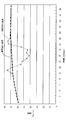
- FIG. 5 is a diagram showing the azimuth data of the trajectory of the vehicle that has traveled in the unforeseen section and the interpolation data calculated from the GPS signal.
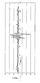
- FIG. 6 is a diagram illustrating an example in which the angular acceleration indicates an abnormal value.
- the vehicle trajectory is detected by performing a calculation process based on the vehicle travel information detected during the travel of the vehicle, and the acquisition of the vehicle travel information and the calculation process will be described below. .
- FIG. 2 shows a configuration for acquiring vehicle travel information.
- the vehicle is provided with a control device 1 for calculating a traveling locus and a vehicle direction by dead reckoning navigation.
- the control device 1 has a configuration in which a memory 12 and an input / output interface are provided with a CPU 11 as a center.
- the CPU 11 of the control device 1 can perform various processes based on a program stored in the memory 12 (storage medium).
- a GPS receiver 2, a gyro 3, an acceleration sensor 4, a vehicle speed sensor 5 and the like are connected to the control device 1 and various data are input.
- the GPS receiver 2 receives radio waves from a plurality of GPS satellites by the GPS antenna 2a and obtains a GPS signal for detecting position information and speed information.
- the gyro 3 (which can function as a yaw rate sensor) acquires information on turning in the vertical direction of the vehicle as the yaw rate value yr_gy of the angular velocity.
- the acceleration sensor 4 (which can function as a lateral acceleration sensor) detects the lateral acceleration gy of the vehicle.
- the vehicle speed sensor 5 acquires data on the traveling speed v of the vehicle.
- the above-mentioned various data are sampled at intervals of, for example, 100 ms (milliseconds), and data is logged in a nonvolatile memory or the like as vehicle running information.
- the time interval for sampling data may be shorter or longer than 100 ms. If the time interval is shortened, the vehicle direction can be detected accurately, and if the time interval is lengthened, the arithmetic processing can be performed in a short time.
- the vehicle trajectory is calculated by the control device 1 based on the vehicle travel information obtained in this way.
- the vehicle trajectory is calculated by the control device 1.
- the vehicle trajectory is calculated based on the vehicle travel information, and the process of calculating the vehicle trajectory at each detection timing of the vehicle travel information is performed. Do not do. Accordingly, the vehicle travel information once accumulated and stored in the above-described non-volatile memory or the like can be subjected to a calculation process using an arithmetic means such as a microcomputer or a personal computer instead of the control device 1.
- the map matching process is performed by calculating the trajectory of the own vehicle using dead reckoning navigation based on the yaw rate value detected by the gyro 3 and the vehicle speed information detected by the vehicle speed sensor 5.
- the control device 1 basically eliminates the above-described error by calculating the vehicle trajectory based on the GPS signal obtained from the GPS receiver 2.
- an unforeseen section may occur where the GPS signal cannot normally calculate the trajectory.
- the accuracy may greatly deteriorate depending on the state of radio waves from a building or the like.
- the traveling locus of the vehicle can be calculated in the preceding and following sections. Therefore, in such an environment, in a section where the radio wave environment deteriorates, the travel locus can be calculated by performing interpolation processing based on the information of the preceding and following travel locus. This is because interpolation can be performed by performing a process for calculating a travel locus after the fact based on the vehicle travel information acquired during travel.
- the interpolation processing performed here can calculate the data of the unexpected section from the Nth order approximation based on the vehicle position data detected in the sections before and after the unexpected section. Further, the result of element decomposition into angular velocity and velocity data obtained from a GPS signal may be converted into a corrected position after being calculated by N-order approximation. This calculation method will be described later.
- the interpolation process is performed by the above method, if the vehicle travels that cannot be estimated from the data of the preceding and following sections, the locus may not be reproduced. Therefore, in the interpolation processing in such an unexpected section, the accuracy is improved by using the locus calculation processing by dead reckoning navigation in combination. Even when a GPS signal cannot be received, information related to traveling in an unforeseen section can be used by acquiring the vehicle traveling information described above.
- dead reckoning navigation when such dead reckoning navigation is employed, there is an unsuitable traveling state. In this case, interpolation processing is also performed based on the calculation results of the preceding and following traveling trajectories. For example, when drift traveling is performed, calculation of the locus by dead reckoning navigation causes an error. Therefore, application of dead reckoning navigation in the unforeseen section is on condition that drift traveling is not performed.
- the vehicle locus calculation process in the present embodiment will be described with reference to FIG. Further, here, for example, a case where the vehicle travels on a travel route including a three-dimensional intersection of circuits as shown in FIG. 3 will be described.
- a travel route including a three-dimensional intersection of circuits as shown in FIG. 3 When traveling on the lower road of such a three-dimensional intersection, GPS radio waves are blocked by the upper road and deteriorate. Therefore, a section including the three-dimensional intersection and a fixed distance before and after the three-dimensional intersection is set as an unexpected section.
- the range of the fixed distance before and after for the unexpected section setting can be set to an appropriate distance in consideration of the reception level of the received GPS signal.
- the section corresponding to the environmental factor section caused by the environment of the road on which travels is present in addition to the road below the three-dimensional intersection described above as the unexpected section.
- Such environmental factors include, for example, various places such as tunnels, under gates, under bridges, arcades, high-rise buildings, roads laid in trenches, or roads with walls on the roadside. Is applicable. Therefore, when these environmental factors exist, a predetermined range before and after this part can be set as an unexpected interval.
- the control device 1 calculates the travel locus of the vehicle based on the information acquired and recorded when the vehicle traveled. In this case, the control device 1 first determines whether or not the vehicle has entered the unexpected section at the vehicle position at each time (S1). Here, in most of the travel route, a GPS signal can be obtained and a locus can be calculated. However, an interpolation process described later is required in an unforeseen section.
- the control device 1 calculates the angular acceleration at that time (S3).
- the control device 1 calculates angular acceleration during traveling and determines that the GPS signal is disturbed when the magnitude is equal to or greater than a threshold value indicating an abnormal level. Are determined as unforeseen intervals. If the angular acceleration value is equal to or smaller than the threshold value (determined as YES in S4), normal trajectory calculation processing is performed based on the GPS signal, assuming that the GPS signal has not deteriorated (S5).
- control device 1 performs the calculation process in the same manner as described above for the vehicle position at the next time. And when the position of the vehicle has entered into the unforeseen section, the control device 1 determines YES in step S2, and subsequently performs a drift determination process (S6).
- the control device 1 calculates the position information by interpolating the locus before and after the unforeseen section according to the situation.
- a locus with higher accuracy than the interpolation process is calculated by applying dead reckoning navigation using the yaw rate value of the gyro 3 or the like. can do. Therefore, a drift determination described later is performed to determine whether dead reckoning navigation is applicable.
- the control device 1 performs an interpolation process by dead reckoning navigation (S8).
- the control device 1 calculates a trajectory corresponding to each measurement point in the unforeseen section based on the data of the locus before and after the unforeseen section and the data such as the yaw rate value by the gyro 3 detected in the unforeseen section.
- the control device 1 performs an interpolation process based on the locus data before and after the unexpected section calculated from the GPS signal (S9).
- it is effective to use curve approximation from data of a predetermined range of trajectory before and after the unexpected section.
- interpolation data is calculated so as to smoothly connect the inside of the unexpected section by applying Nth order (third order or higher) approximation. can do.
- the control device 1 can calculate the trajectory of the travel route as a travel trajectory close to the actual travel trajectory by repeatedly executing the above processing.
- the travel locus can be accurately calculated by performing interpolation processing or using dead reckoning navigation.
- control apparatus 1 does not perform a locus
- the trajectory calculation process is separately performed for the route for which the trajectory has not been calculated, and the trajectory calculation process is performed for the unexpected interval that is set when the unexpected interval and the angular acceleration are equal to or greater than the threshold.
- the trajectory of the vehicle can be calculated based on the yaw rate value signal output from the gyro 3.
- drift determination process a calculation formula indicating the relationship among the lateral acceleration gy [m / s2], the yaw rate value yr_gy [° / s] by the gyro 3 and the vehicle speed v [m / s] is used.
- the drift state is determined by substituting the data at each time point into the calculation formula and not satisfying the relational expression.
- the drift judgment formula is based on the relationship shown by the following formula. That is, in the grip state where no drift occurs, the yaw rate value yr_gy detected by the gyro 3 is equal to the value obtained by dividing the lateral acceleration gy by the vehicle speed v, and therefore the relationship of the following expression (1) is established. .
- yr_gy gy / v (1)
- yr_gy Yaw rate value ([° / s], [dps])
- v Vehicle speed [m / s]
- gy lateral acceleration sensor value [m / s2]
- the drift state can be determined when the difference between the two is calculated and becomes equal to or greater than the determination value.
- the difference value ⁇ between the two is obtained by the equation (2).
- T (b0 + b1z-1 + b2z-2 + b3z-3 + b4z-4) / (1 + a1z-1 + a2z-2 + a3z-3 + a4z-4) (4)
- the value T obtained as described above is compared with a drift determination reference value (for example, 0.2), and the drift state is determined when a difference larger than this occurs.
- FIG. 4 shows changes in the detected value ⁇ _gy and the filter output T detected over time. While the detection value ⁇ _gy varies finely with time, the filter output T can be obtained with a small variation by removing the high frequency component, thereby determining a state that exceeds the positive and negative drift determination values. To do.
- the process changes to a process (S8) for calculating the vehicle trajectory in the unexpected section based on the yaw rate value yr_gy of the gyro 3.
- the drift state detection start time point and the detection end time point are provided as a process for providing a so-called hysteresis so that the judgment switching is not unstable in the vicinity of the judgment reference value when performing the drift judgment. It is advisable to make the judgment conditions different between and.
- an error of 10 [° / s] or less is calculated at an earlier stage than the time point when the drift state is determined by the above relational expression including the yaw rate value yr_gy, the lateral acceleration gy, and the vehicle speed v. There is. Therefore, even when the yaw rate value yr_gy itself reaches a certain threshold level, the error is reduced by performing the drift determination.
- the determination is made as follows.
- the determination conditions are made different between the detection start time and the detection end time of the drift state.
- the end determination of the drift state a state in which the state satisfying the determination condition continues for a certain time (for example, 1 second) is determined, and thereby the end of the drift state is determined.
- the determination condition at the detection start time of the drift state is the time when the absolute value of the value T converted so as to cut the high-frequency component through the Butterworth filter shown in the equation (4) becomes 0.2 or more.
- the first condition shown in FIG. the value of the relative vehicle direction DRrelD (t) of the vehicle direction detected by the gyro 3 at time t is set to an angle with the value of the relative vehicle direction DRrelD (t ⁇ 1) at the previous time t ⁇ 1. Whether or not the deviation is 10 degrees or more is set as the second condition shown in Expression (6). Then, the drift state is determined when either the first condition or the second condition is detected.
- the determination condition at the end of detection of the drift state is that the absolute value of the value T converted so as to cut the high-frequency component through the Butterworth filter shown in Equation (4) is 0.1 or less. This time is defined as the first condition shown in Equation (7).
- the value of the relative vehicle direction DRrelD (t) of the vehicle direction detected by the yaw rate value yr_gy at the time t is set to an angle with the value of the relative vehicle direction DRrelD (t ⁇ 1) at the previous time t ⁇ 1.
- the second condition shown in Expression (8) is that the angle is within 10 degrees.
- the determination of the end of the drift state is based on the condition that the state satisfying both the first condition and the second condition has continued for 1 second.
- the section to be interpolated is applied when it is determined that it is an unexpected section or a section where the angular acceleration is equal to or greater than a threshold value.
- the unforeseen section when the unforeseen section is set in advance, the unforeseen section can be set as the interpolation section. Further, for the unexpected section set when the angular acceleration is equal to or greater than the threshold, the interpolation section is calculated after calculating the interpolation section as described later.
- the correction section data is data for 1.5 seconds before and after the correction section, and third-order approximate correction is performed for the speed V and the direction ⁇ , and the corrected speed Vc and direction ⁇ c are calculated.
- the accuracy can be improved by using an approximation for each by performing an elemental decomposition into an angular velocity and a velocity.
- FIG. 5 shows the experimental results when approximate interpolation is performed using elements (angular velocities).
- the data of the speed V changes so as to increase once with the progress of time, and then fluctuates so as to decrease and increase again.
- an unexpected section is set including a section in which the angular velocity is abnormally changed, and a trajectory in the unexpected section is calculated by an approximate calculation based on the trajectory data of the preceding and following sections. The calculation results are as shown in the figure.
- the speed before and after the unexpected section is approximated by a smooth curve, and the data of the interpolation section is estimated.
- the unforeseen sections (S3, S4) set during the locus calculation process other than the previously set unforeseen sections will be described.
- This is set because it may not be possible to deal with the following cases by simply performing interpolation processing for a preset unexpected interval. That is, it can be specified in advance that a building or a building such as a side wall is a section where the reception level of the GPS signal is lowered, but there is a section where a tree or an unexpected object is present and the radio wave is disturbed. Sometimes. As trees and the like grow, there is a high possibility of interference with radio waves. Therefore, a problem situation occurs depending on the season, and this is set as an unexpected interval.
- the direction of a running vehicle does not change suddenly unless a sudden change such as the occurrence of a drift state or a collision occurs.
- the vehicle trajectory does not suddenly change greatly.
- the angular acceleration is calculated from the velocity vector of the GPS signal, and if the angular acceleration exceeds a certain value, it is considered as an unforeseen interval because it is an abnormal state, that is, the interval where the GPS signal cannot be received as a normal signal. I set it.
- FIG. 6 there is a section where the angular acceleration greatly varies with time. It can be inferred that this section is fluctuating due to the unstable reception level of the GPS signal, rather than a sudden trajectory change. Therefore, such a situation is calculated and an unexpected section is set.
- the azimuth ⁇ (n) of the velocity vector V (n) is expressed by the equation (14) by the components VN (n) (north-south direction component) and VE (n) (east-west direction component) of the nth velocity vector V (n). Can be sought.
- Direction ⁇ (n) arctan (VN (n) / VE (n)) ⁇ 180 / ⁇ [°] (14)
- Angular velocity ⁇ (n) [ ⁇ (n) ⁇ (n ⁇ 1)] ⁇ 10 [° / s] (15)
- Angular acceleration ⁇ (n) ⁇ (n) ⁇ (n ⁇ 1) [° / s2] (16) Determination formula
- the control device 1 uses the GPS signal to calculate the sections before and after the unforeseen section. By performing interpolation processing based on the trajectory, it can be obtained approximately.
- the travel locus in the unexpected section is calculated by performing Nth order (third order or higher) approximation line, that is, curve approximation, using the travel locus data calculated for a certain section before and after the unexpected section. Therefore, it is possible to obtain the locus in the unexpected section as a locus connected by a smooth curve. Further, in this case, a relatively accurate trajectory can be calculated by the third-order approximation in consideration of the fact that the vehicle travels close to a circular orbit without using a fourth-order or higher-order approximation line.
- the drift state in the unforeseen section is determined, and if it is in the drift state, an interpolation process is performed.
- the trajectory of the unexpected section can be calculated by dead reckoning navigation. As a result, accurate trajectory calculation processing using dead reckoning navigation can be performed.
- an environmental factor section such as a place where the GPS signal reception level is low or a place where the reception level is disturbed is specified in advance as the geographical condition of the travel route.
- the control device 1 can calculate the trajectory of the unexpected section so as to be connected by the smooth trajectory by the interpolation process regardless of the vehicle travel information acquired during the travel of the unexpected section.
- the environmental factor section which is an unforeseen section, is set as a section where a component that blocks radio waves from GPS satellites or a component that disturbs radio waves from GPS satellites exists above or to the side of the travel route. I did it.
- the control device 1 interpolates the trajectory of the unforeseen section regardless of the vehicle travel information acquired at the time of traveling for the unpredictable section where the level of the GPS signal is lower than other areas, for example, at the lower part of the three-dimensional intersection. It can be calculated so as to connect with a smooth trajectory.
- an unexpected section setting process is performed for setting the unexpected section based on the value of the angular acceleration calculated from the GPS signal.
- the control device 1 detects an abnormal section where the angular acceleration value calculated from the GPS signal is equal to or greater than the first determination value (20 ° / s2) in the unexpected section setting process, and the detected abnormality A section including a range of a predetermined time (1 second) before and after the section is set as an unexpected section.
- the unexpected section including the abnormal section where the GPS signal level becomes unstable and the section of the boundary area the trajectory is reliably calculated when performing interpolation processing from the trajectory before and after the unexpected section.
- a highly accurate trajectory can be interpolated by using the formed portion as a basis.
- the control device 1 decomposes the angular velocity in the unexpected section from the travel locus calculated for the fixed section before and after the unexpected section into its component azimuth and speed, and the nth order (n is Since the calculation is performed by approximating with an approximation line of an integer of 3 or more, a trajectory close to the actual vehicle trajectory can be accurately calculated.
- the process of performing the drift determination (S6) or the angular acceleration determination (S3) is performed after determining the unexpected section (S2).
- the order of these may be changed. It can be changed to adopt a flow for determining processing when a combination of conditions matches.
- the setting of the unexpected section can be performed before the vehicle travels, or can be performed prior to the calculation process after the vehicle travel information is acquired after the vehicle travels.
- the drift determination may be performed as necessary, and if the determination process is not performed, the interpolation process can be performed by N-order approximation.
- the drift determination can be performed based on the information. it can.
- the trajectory is calculated by approximating the Nth order approximation with the third order approximation line, but it is also possible to apply a fourth order approximation line or more.
- the threshold value can be set to an appropriate value. It is effective to set an appropriate level from the relationship between the detection signal and the noise level.
- the drift determination value for determining the drift state can be set at an appropriate level according to various factors such as the vehicle running state, road pattern, or detection signal state. Similarly, an appropriate level can be set for the drift end determination value. Thereby, adjustments such as increasing the sensitivity of determination of the drift state or avoiding erroneous determination according to the noise level can be performed.
- the high-frequency signal component is cut from the value of the difference signal ⁇ _gy of the lateral acceleration by the Butterworth filter, but any filter other than the Butterworth filter can be applied as long as it functions as a low-pass filter.
Landscapes
- Engineering & Computer Science (AREA)
- Radar, Positioning & Navigation (AREA)
- Remote Sensing (AREA)
- Physics & Mathematics (AREA)
- General Physics & Mathematics (AREA)
- Computer Networks & Wireless Communication (AREA)
- Automation & Control Theory (AREA)
- Navigation (AREA)
Abstract
GPS信号の不測区間の軌跡を精度良く算出する技術を提供する。一実施形態によれば、GPS受信機(2)、ジャイロ(3)、加速度センサ(4)と、車速センサ(5)により所定時間間隔で車両走行情報を測定する。制御装置(1)により、この車両走行情報から走行軌跡を算出する。GPS信号の不測区間を予め設定あるいは角加速度から判定して設定する。制御装置(1)は、不測区間以外で安定したGPS信号に基づいて軌跡を算出する。制御装置(1)は、GPS信号が不安定となる区間を不測区間とし、N次近似で補間処理をする。制御装置(1)は、不測区間では、ドリフト判定をしてドリフト状態でないときには推測航法で補間処理を行い、ドリフト状態ではN次近似で補間処理をする。
Description
本出願は、2013年2月18日に出願された日本国特許出願2013-29033号に基づくものであり、ここにその開示を参照により援用する。
本開示は、車両軌跡算出方法に関する。
道路を走行する車両の軌跡を算出するものとして、GPS受信機で受信するGPS信号を用いたものがある。しかし、GPS信号に基づいて算出された位置情報はGPS衛星からの電波の状態によりその精度が大きく変化することがある。特に、車両が電波を受信困難な場所を通過する場合には、電波遮断状態あるいはこれに近い状況となっているので、GPS信号による測位そのものができなくなることがあり、位置を算出することができない。
本開示は、上記事情を考慮してなされたもので、その目的は、車両の走行により取得した車両走行情報に基づいて車両軌跡を算出する場合に、GPS信号が正常に受信できない場合でも走行軌跡を算出することができるようにした車両軌跡算出方法を提供することにある。
本開示の一例の車両軌跡算出方法は、走行中の車両のGPS受信機により所定時間間隔で受信したGPS信号に基づいて走行経路における車両の走行軌跡を算出するようにした車両軌跡算出方法であって、GPS信号に基づいた走行軌跡が正常に算出できない不測区間では、不測区間の前後の区間について算出した走行軌跡に基いて補間処理を行なって不測区間内の走行軌跡を算出する。
このような車両軌跡算出方法によれば、車両に設けられたGPS受信機により走行中にGPS信号を受信して走行経路における車両の走行軌跡を算出する場合に、GPS信号の受信状態が何らかの原因により走行軌跡を正常に算出できない場合があり、これを不測区間とする。この不測区間における車両の走行軌跡は、その不測区間の前後の区間について算出した走行軌跡に基いて補間処理を行うことで、近似的に得ることができる。
本開示についての上記および他の目的、特徴や利点は、添付の図面を参照した下記の詳細な説明から、より明確になる。添付図面において
図1は、一実施形態を示す車両データから車両の軌跡を算出する処理の流れを示す図である。
図2は、走行中の車両の状態を示す車両情報を取得するための構成図である。
図3は、不測区間の地形と車両の軌跡を示す説明図である。
図4は、ドリフト判定を行う場合の信号の出力例を示す図である。
図5は、不測区間を走行した車両の軌跡の方位のデータとGPS信号により算出した補間データを示す図である。
図6は、角加速度が異常値を示す場合の例を示す図である。
以下、本開示の一実施形態について図1から図6を参照して説明する。なお、この実施形態では、車両の走行時に検出した車両走行情報に基いて、演算処理を行うことで車両軌跡を検出するもので、車両走行情報の取得および演算処理について以下に説明するものである。
図2は、車両走行情報を取得するための構成を示している。車両には、推測航法による走行軌跡および車両方位を計算するための制御装置1が備えられている。制御装置1は、CPU11を中心としてメモリ12や入出力インターフェースなどが設けられる構成である。制御装置1のCPU11は、メモリ12(記憶媒体)に記憶されたプログラムに基づき、様々な処理を行うことができる。この制御装置1には、GPS受信機2、ジャイロ3、加速度センサ4、車速センサ5などが接続され、各種のデータが入力される。
GPS受信機2は、GPSアンテナ2aにより複数個のGPS衛星からの電波を受信して位置情報や速度情報を検出するためのGPS信号を得る。ジャイロ3(ヨーレートセンサとして機能可能)は、車両の垂直方向での旋回の情報を角速度のヨーレート値yr_gyとして取得する。加速度センサ4(横加速度センサとして機能可能)は、車両の横方向加速度gyを検出する。車速センサ5は、車両の走行速度vのデータを取得する。
上記した各種データは、例えば100ms(ミリ秒)間隔でサンプリングされ、これを車両走行情報として不揮発性メモリなどにデータログをする。この場合、データをサンプリングする時間間隔は、100ms間隔以外に、これよりも短くても良いし、長くても良い。時間間隔を短くすれば車両方位の検出を精度良く行え、長くすれば演算処理を短時間で実施することができる。
このようにして取得された車両走行情報に基づいて制御装置1により車両の軌跡を算出する。なお、図2の構成では、車両の軌跡を制御装置1により算出する構成としている。この実施形態では前述のようにして車両走行情報を取得した後に、その車両走行情報に基づいて車両の軌跡を算出するものであり、車両走行情報の検出タイミング毎に車両の軌跡を算出する処理を行うのではない。したがって、前述の不揮発性メモリなどに一旦車両走行情報を蓄積して記憶させたものを、制御装置1ではなく、別途にマイコンやパソコンなどの演算手段を用いて算出処理をすることもできる。
次に、上記構成において取得される車両走行情報に基づいて車両の軌跡を算出する過程について説明する。まず、一般的なナビゲーション装置では、ジャイロ3により検出されるヨーレート値や車速センサ5により検出される車速情報により推測航法を用いて自車の軌跡を算出してマップマッチング処理が行われる。
しかし、例えばサーキット等において極限走行が行われることを想定すると、車両がドリフト走行などを行う場合には推測航法では実際の挙動と異なる軌跡を描く場合がある。そこで、この実施形態においては、制御装置1により、基本的にはGPS受信機2から得られるGPS信号に基づいて車両軌跡を算出することで上記した誤差を解消させるようにしている。
そして、この基本前提において、GPS信号が正常に軌跡を算出できなくなる不測区間が発生することがある。例えば、ビル等による電波の状態によりその精度が大きく劣化することがある。絶対位置で言うと走行経路の環境によって電波が建物などによって反射するなどの現象があり、結果的にマルチパスの影響で約100m程度の区間において劣化が発生することがある。
しかし、サーキット走行等では、道路近傍にビル等の建物があまり存在せず、全般的に比較的受信環境が良い状況である。そして、立体交差が存在するサーキットにおいては、立体交差の下側の道路通過等では短時間の電波環境の劣化が発生するものの、前後の区間においては車両の走行軌跡を算出することができる。そこで、このような環境では、電波環境が劣化する区間では、前後の走行軌跡の情報により補間処理を行なって走行軌跡を算出することができる。これは、走行中に取得した上記車両走行情報に基づいて、事後に走行軌跡の算出する処理を実施することで補間を実施できるからである。
なお、ここで実施する補間処理は、不測区間の前後の区間において検出された車両の位置データに基いて、不測区間のデータをN次近似より算出することができる。また、GPS信号から得られる角速度と速度のデータに要素分解した結果をそれぞれN次近似して算出した後に補正した位置へ変換しても良い。この算出方法については後述する。
なお、上記方法により補間処理を行う場合に、前後の区間のデータからでは推測できない走行をされた場合、その軌跡を再現できない場合がある。そこで、このような不測区間での補間処理では、推測航法による軌跡の算出処理も併用することで精度の向上を図るようにしている。GPS信号を受信できない場合でも、前述した車両走行情報を取得していることで、不測区間内の走行に関する情報を利用することができる。
一方で、このような推測航法を採用する場合には不向きな走行状態があり、この場合にはやはり前後の走行軌跡の算出結果に基づいて補間処理をする。例えば、ドリフト走行がなされている場合には、推測航法による軌跡の算出は逆に誤差を生ずることとなる。そこで、不測区間における推測航法の適用は、ドリフト走行が行われていないことを条件とするものである。
次に、本実施形態における車両の軌跡の算出処理について図1を参照して説明する。また、ここでは、例えば、図3に示すようなサーキットの立体交差部を含んでいる走行経路を走行した場合で説明する。このような立体交差部の下側の道路を走行する場合には、上側の道路によりGPS電波が遮られて劣化する。そこで、この立体交差部とその前後の一定距離を含む区間を不測区間として設定している。不測区間設定のための前後の一定距離の範囲は、受信するGPS信号の受信レベルを考慮して適宜の距離に設定することができる。
なお、不測区間として該当するのは、上記した立体交差の下側の道路以外に、走行する道路の環境に起因した環境要因区間に相当するものが存在する区間である。このような環境要因としては、例えばトンネル内、ゲートの下、橋の下、アーケード、高層ビル街、溝内に敷設されている道路、あるいは路側に壁面が形成されている道路などのさまざまな場所が該当する。したがって、これらの環境要因が存在する場合には、この部分を含めた前後の所定範囲を不測区間として設定することができる。
制御装置1は、前記したように、車両が走行した際に取得して記録された情報に基いて、車両の走行軌跡を算出する。この場合、制御装置1は、まず、各時刻の車両位置において車両が不測区間に進入しているか否かを判定する(S1)。ここで、走行経路の大部分においては、GPS信号を取得して軌跡を算出することができるが、不測区間では後述する補間処理が必要となる。
制御装置1は、不測区間に進入していない場合(S2でNOと判断)には、その時点での角加速度を算出する(S3)。ここでは、前述したように、制御装置1は、走行中の角加速度を算出してその大きさが異常レベルを示す閾値以上となる場合にGPS信号が乱れていると判断してこのような区間を不測区間として判定する。そして、角加速度の値が閾値以下である場合(S4でYESと判断)には、GPS信号の劣化が発生していないとして、GPS信号に基づいて通常の軌跡算出処理を実施する(S5)。
以下、次の時刻の車両位置についても、制御装置1は、上記と同様に算出処理を行う。そして、車両の位置が不測区間に進入している場合には、制御装置1は、ステップS2でYESと判断して続いてドリフト判定処理を実施する(S6)。
不測区間における車両の軌跡の算出は、GPS信号のレベルが低下しているか不安定になっている状態などで、GPS信号による算出が精度良くできない。そこで、この不測区間では、制御装置1は、状況に応じてその不測区間の前後の軌跡から位置情報を補間して算出する。この場合、不測区間での車両の走行状態として、ドリフト状態が発生していない場合には、ジャイロ3などのヨーレート値を用いて推測航法を適用することで補間処理よりも精度の高い軌跡を算出することができる。そこで、後述するドリフト判定を行なって推測航法が適用可能な否かを判定するものである。
まず、ドリフト判定処理(S6)でドリフト状態が発生していない場合(S7でNOと判断)には、制御装置1は、推測航法による補間処理を実施する(S8)。制御装置1は、不測区間の前後の軌跡のデータと、不測区間内で検出されたジャイロ3によるヨーレート値などのデータに基いて不測区間内の各測定点に対応して軌跡を算出する。
一方、不測区間においてドリフト状態と判定されている場合(S7でYESと判断)には、推測航法を用いると車両のドリフトによる誤差が発生する。そこで、制御装置1は、GPS信号から算出した不測区間の前後の軌跡のデータに基づいて補間処理を行う(S9)。この場合、不測区間の前後の所定範囲の軌跡のデータから曲線近似を用いることが有効で、例えばN次(3次以上)近似を適用して不測区間内を滑らかにつなぐように補間データを算出することができる。
制御装置1は、以上のような処理を繰り返し実行することで、走行経路の軌跡を実際の走行軌跡に近い走行軌跡として算出することができる。特に、GPS信号が乱れて走行軌跡が正しく算出できない不測区間内においても、補間処理を行ったり、推測航法を用いたりして走行軌跡を正確に算出することができる。
なお、制御装置1は、各測定点について逐次的に軌跡算出処理を行うのではなく、不測区間あるいは角加速度が閾値以下となる場合の軌跡については先にGPS信号に基づいた算出処理(S5)を行い、軌跡が算出されていない経路について別途軌跡算出処理を実行して不測区間と角加速度が閾値以上となる場合に設定される不測区間について軌跡の算出処理がなされる。
次に、上記した図1のステップS6におけるドリフト判定処理について説明する。ここでは、ドリフト走行のような極限走行をする場合は、車両の軌跡をジャイロ3から出力されるヨーレート値の信号に基づいて算出することができる。
ドリフト判定処理では、横方向加速度gy[m/s2]、ジャイロ3によるヨーレート値yr_gy[°/s]、車速v[m/s]の関係を示す算出式を用いる。算出式に各時点でのデータを代入してその関係式を満たさない状態をもってドリフト状態を判定するものである。
ドリフト判定式は、次式で示す関係を基準としている。すなわち、ドリフトが発生していないグリップ状態では、ジャイロ3により検出されるヨーレート値yr_gyは横方向加速度gyを車速vで除した値に等しくなるから、次式(1)の関係が成立している。
yr_gy=gy/v (1)
yr_gy:ヨーレート値([°/s]、[dps])
v:車速[m/s]
gy:横方向加速度センサ値[m/s2]
一方、ドリフト状態では式(1)の関係が崩れるので、両者の差を算出して判定値以上となるときにドリフト状態を判定することができる。この場合、ヨーレート値yr_gyをラジアン値yrに変換してから両者の差の値ωを式(2)で求める。加速度の差の値ωを、式(3)に示すような重力加速度G(=9.8[m/s2])を基準とした値ω_gyに変換する。
yr_gy:ヨーレート値([°/s]、[dps])
v:車速[m/s]
gy:横方向加速度センサ値[m/s2]
一方、ドリフト状態では式(1)の関係が崩れるので、両者の差を算出して判定値以上となるときにドリフト状態を判定することができる。この場合、ヨーレート値yr_gyをラジアン値yrに変換してから両者の差の値ωを式(2)で求める。加速度の差の値ωを、式(3)に示すような重力加速度G(=9.8[m/s2])を基準とした値ω_gyに変換する。
yr=(yr_gy)×2π/360[rad/s]
ω=gy-(yr×v) (2)
ω_gy=ω/9.8 (3)
この場合、算出したω_gyの値は、検出出力を直接変換したものなので、ばらつきが大きい。そこで、ω_gyの値をバタワースフィルタなどのローパスフィルタを介して高周波成分をカットするように変換した値T(式(4))によって判定を行う。
ω=gy-(yr×v) (2)
ω_gy=ω/9.8 (3)
この場合、算出したω_gyの値は、検出出力を直接変換したものなので、ばらつきが大きい。そこで、ω_gyの値をバタワースフィルタなどのローパスフィルタを介して高周波成分をカットするように変換した値T(式(4))によって判定を行う。
T=(b0+b1z-1+b2z-2+b3z-3+b4z-4)/
(1+a1z-1+a2z-2+a3z-3+a4z-4) (4)
上記のようにして得られた値Tをドリフト判定基準値(例えば0.2)と比較してこれ以上となる差が発生している場合にドリフト状態を判定する。図4は時間の経過と共に検出される検出値ω_gyとフィルタ出力Tの変化の様子を示している。検出値ω_gyが時間と共に細かく変動しているのに対して、フィルタ出力Tはその高い周波数成分を除去した少ない変動で得ることができ、これによって正および負のドリフト判定値以上となる状態を判定する。
(1+a1z-1+a2z-2+a3z-3+a4z-4) (4)
上記のようにして得られた値Tをドリフト判定基準値(例えば0.2)と比較してこれ以上となる差が発生している場合にドリフト状態を判定する。図4は時間の経過と共に検出される検出値ω_gyとフィルタ出力Tの変化の様子を示している。検出値ω_gyが時間と共に細かく変動しているのに対して、フィルタ出力Tはその高い周波数成分を除去した少ない変動で得ることができ、これによって正および負のドリフト判定値以上となる状態を判定する。
そして、上記のようにしてドリフト状態を判定した場合には、不測区間における車両の軌跡をジャイロ3のヨーレート値yr_gyにより算出する処理(S8)に変更する。この場合、ドリフト判定をする際の判定基準値近傍で判定の切り替わりが不安定にならないようにするため、いわゆるヒステリシスを持たせる処理として、後述するように、ドリフト状態の検出開始時点と検出終了時点とで判定条件を異ならせるようにすると良い。
さらに、実際の車両運動ではヨーレート値yr_gyと横方向加速度gyと車速vからなる上記関係式でドリフト状態を判定する時点よりも早い段階で10[°/s]以下の誤差が算出されてしまうことがある。そこで、ヨーレート値yr_gyそのものがある閾値レベルに達した場合も、ドリフト判定をすることによりその誤差を低減する。
具体的には、次のようにして判定する。なお、ここではドリフト判定が判定値近傍で不安定にならないようにするため、ドリフト状態の検出開始時点と検出終了時点とで判定条件を異ならせるようにしている。また、ドリフト状態の終了判定については、判定条件を満たす状態が一定時間(例えば1秒)継続する状態を判定し、これによりドリフト状態の終了を判定するようにしている。
ドリフト状態の検出開始時点の判定条件は、前述した式(4)に示すバタワースフィルタを介して高周波成分をカットするように変換した値Tの絶対値が0.2以上となる時点を式(5)に示す第1条件とする。また、時刻tでジャイロ3により検出される車両方位の相対車両方位DRrelD(t)の値が、前回の時刻t-1の時点での相対車両方位DRrelD(t-1)の値と角度にして10度以上ずれているかどうかを式(6)に示す第2条件としている。そして、第1条件あるいは第2条件のいずれかが検出された時点でドリフト状態を判定する。
|T(n)|≧0.2 (5)
|DRrelD(t)-DRrelD(t-1)|≧10[dps] (6)
また、同様にして、ドリフト状態の検出終了時点の判定条件は、前述した式(4)に示すバタワースフィルタを介して高周波成分をカットするように変換した値Tの絶対値が0.1以下となる時点を式(7)に示す第1条件とする。また、時刻tでヨーレート値yr_gyにより検出される車両方位の相対車両方位DRrelD(t)の値が、前回の時刻t-1の時点での相対車両方位DRrelD(t-1)の値と角度にして10度以内になる
ことを式(8)に示す第2条件としている。前述のように、ドリフト状態の終了判定は、第1条件および第2条件のいずれも満たす状態が1秒継続したことを条件としている。
|DRrelD(t)-DRrelD(t-1)|≧10[dps] (6)
また、同様にして、ドリフト状態の検出終了時点の判定条件は、前述した式(4)に示すバタワースフィルタを介して高周波成分をカットするように変換した値Tの絶対値が0.1以下となる時点を式(7)に示す第1条件とする。また、時刻tでヨーレート値yr_gyにより検出される車両方位の相対車両方位DRrelD(t)の値が、前回の時刻t-1の時点での相対車両方位DRrelD(t-1)の値と角度にして10度以内になる
ことを式(8)に示す第2条件としている。前述のように、ドリフト状態の終了判定は、第1条件および第2条件のいずれも満たす状態が1秒継続したことを条件としている。
|T(n)|≦0.1 (7)
|DRrelD(t)-DRrelD(t-1)|≦10[dps] (8)
上記した式(5)と式(7)では、ドリフト判定値が異なり、次式(9)で示す範囲では、ヒステリシス領域として判定結果が不安定になることを防止している。
|DRrelD(t)-DRrelD(t-1)|≦10[dps] (8)
上記した式(5)と式(7)では、ドリフト判定値が異なり、次式(9)で示す範囲では、ヒステリシス領域として判定結果が不安定になることを防止している。
0.1<|T(n)|<0.2 (9)
以上のようにして、式(5)~(9)の第1条件および第2条件を用いてドリフト判定を行うことで、車両のドリフト状態の開始時点の判定および終了時点の判定を確実にし、且つ車両の軌跡を正確に検出することができる。
以上のようにして、式(5)~(9)の第1条件および第2条件を用いてドリフト判定を行うことで、車両のドリフト状態の開始時点の判定および終了時点の判定を確実にし、且つ車両の軌跡を正確に検出することができる。
次に、不測区間における車両の軌跡を、不測区間の前後の区間においてGPS信号により算出した軌跡からN次近似による補間処理により算出する方法について説明する。補間処理をする区間は、不測区間あるいは角加速度が閾値以上となる区間と判定される場合に適用するものである。
なお、不測区間が予め設定されている場合には、その不測区間を補間区間とすることができる。また、角加速度が閾値以上となる場合に設定される不測区間については、後述するようにして補間区間を算出してから補間処理を行う。
補間区間が算出されると、その補間区間の前後の所定期間の軌跡のデータを用いて近似計算を行う。ここでは、例えば前後の1.5秒間の期間の走行軌跡のデータを用いて、N次の近似線を算出して補間処理を行う。
具体的には、補正区間のデータを、補正区間の前後の1.5秒間のデータで、速度V、方位θについて3次の近似補正を実施し、補正後の速度Vc、方位θcを算出する。この場合、車両の軌道は円運動に近い動きとなることから、角速度と速度へ要素分解をすることで、それぞれに対して近似を用いることで精度を向上させることができる。
速度V=[(VN)2+(VE)2]1/2 (10)
方位θ=arctan(VN/VE) (11)
得られた補正後の速度Vと方位θとで、速度成分VNc、VEcへ再変換する。
方位θ=arctan(VN/VE) (11)
得られた補正後の速度Vと方位θとで、速度成分VNc、VEcへ再変換する。
VNc=Vc×sinθc (12)
VEc=Vc×cosθc (13)
このように、要素(角速度)により近似補間したした場合の実験結果を図5に示している。この図5に示す場合には、速度Vのデータが時間の進行に伴って一旦大きくなるように変化し、その後、大きく減少して再び増大するように変動している。このように異常に角速度が変化している区間を含んで不測区間が設定されており、この不測区間内の軌跡が前後の区間の軌跡のデータに基いて近似計算により算出される。算出結果は図示のとおりである。不測区間の前後の速度に対して滑らかな曲線で近似されており、補間区間のデータが推定されている。
VEc=Vc×cosθc (13)
このように、要素(角速度)により近似補間したした場合の実験結果を図5に示している。この図5に示す場合には、速度Vのデータが時間の進行に伴って一旦大きくなるように変化し、その後、大きく減少して再び増大するように変動している。このように異常に角速度が変化している区間を含んで不測区間が設定されており、この不測区間内の軌跡が前後の区間の軌跡のデータに基いて近似計算により算出される。算出結果は図示のとおりである。不測区間の前後の速度に対して滑らかな曲線で近似されており、補間区間のデータが推定されている。
次に、予め設定された不測区間以外に軌跡の算出処理時に設定される不測区間(S3、S4)について説明する。これは、予め設定された不測区間について補間処理をするだけでは、次のような場合に対応できないことがあるため設定するものである。すなわち、建物や側壁などの建造物などはGPS信号の受信レベルが低下する区間であることが予め特定することができるが、樹木や不測の物体が存在して電波を乱している区間が生ずることがある。樹木などは成長することにともなって、電波を妨害する可能性が高くなるため、季節によっては問題となる状況が発生するものであり、これを不測区間として設定するものである。
一般に、走行中の車両の方位は、ドリフト状態の発生や衝突などの急激な変化が起こっていない限り、急激な変化を生ずることはない。つまり、車両の軌跡は突然大きな変動は起こさないと言える。この点に着目し、GPS信号の速度ベクトルより角加速度を算出し、その角加速度がある値を超えた場合は異常状態すなわちGPS信号が正常な信号として受信できていない区間であるとして不測区間として設定するようにした。
例えば、図6に示すように、時間と共に角加速度が大きく変動する区間が生じている。この区間は、急激な軌跡の変化が生じているというより、GPS信号の受信レベルが不安定になっていることに起因して変動を生じているものと推測できる。そこで、このような状況を算出して不測区間を設定する。
以下、異常箇所の検出方法と補正区間の算出方法を示す。
n番目の速度ベクトルV(n)の成分VN(n)(南北方向成分)およびVE(n)(東西方向の成分)によって速度ベクトルV(n)の方位θ(n)を式(14)により求めることができる。
方 位 θ(n)=arctan(VN(n)/VE(n))×180/π[°]
(14)
角速度 ω(n)=[θ(n)-θ(n-1)]×10[°/s] (15)
角加速度α(n)=ω(n)-ω(n-1)[°/s2] (16)
判定式 |α(n)|≧20[°/s2] (17)
となるデータを検出する。すなわち、角加速度αの値の絶対値が20[°/s2]以上となる場合が異常区間の対象となる。不測区間としては、次の区間を設定する。
(14)
角速度 ω(n)=[θ(n)-θ(n-1)]×10[°/s] (15)
角加速度α(n)=ω(n)-ω(n-1)[°/s2] (16)
判定式 |α(n)|≧20[°/s2] (17)
となるデータを検出する。すなわち、角加速度αの値の絶対値が20[°/s2]以上となる場合が異常区間の対象となる。不測区間としては、次の区間を設定する。
式(17)で検出される区間に対して、その前後のデータについて、
α(n)≧10[°/s2] (18)
を満たさなくなる1秒間の区間を含めて不測区間として設定する。
α(n)≧10[°/s2] (18)
を満たさなくなる1秒間の区間を含めて不測区間として設定する。
データ列を以下のように得られているとする。
α(p-10)、…、α(p)、…、α(-1)、α(0)、α(1)、…、α(q)、…、α(q+10)
α(0)≧20[°/s2]
α(p-10)、…、α(p)、α(q)、…、α(q+10)<10[°/s2]
ここで、α(0)が式(17)を満たしているとし、α(0)を含んだ上記区間中で式(18)を満たさなくなる最初の点から10ポイント(すなわち1秒間)を含めた区間を不測区間として設定する。これにより、始点α(p-10)、終点α(q+10)とした不測区間が得られ
る。制御装置1は、このような不測区間を検出して設定し、この不測区間について前述した補間処理を実施する。
α(0)≧20[°/s2]
α(p-10)、…、α(p)、α(q)、…、α(q+10)<10[°/s2]
ここで、α(0)が式(17)を満たしているとし、α(0)を含んだ上記区間中で式(18)を満たさなくなる最初の点から10ポイント(すなわち1秒間)を含めた区間を不測区間として設定する。これにより、始点α(p-10)、終点α(q+10)とした不測区間が得られ
る。制御装置1は、このような不測区間を検出して設定し、この不測区間について前述した補間処理を実施する。
上記実施形態によれば次のような効果を得ることができる。
第1に、GPS受信機2により受信したGPS信号の受信状態が何らかの原因により走行軌跡を正常に算出できない不測区間について、制御装置1により、その不測区間の前後の区間についてGPS信号により算出した走行軌跡に基いて補間処理を行うことで、近似的に得ることができる。
第2に、補間処理では、不測区間の前後の一定区間について算出した走行軌跡のデータを用いて不測区間内の走行軌跡をN次(3次以上)の近似線すなわち曲線近似を行なって算出するので、不測区間内における位置をなめらかな曲線でつないだ軌跡として得ることができる。また、この場合に、4次以上の高次の近似線を採用しなくとも、車両の走行が円軌道に近いことを踏まえて3次の近似で比較的正確な軌跡を算出することができる。
第3に、GPS受信機2以外に、ジャイロ3、横加速度センサ4および車速センサ5を備える構成では、不測区間におけるドリフト状態の判定を行なって、ドリフト状態である場合には補間処理を行い、ドリフト状態でない場合には、不測区間の軌跡を推測航法により算出することができる。これにより、推測航法を併用した正確な軌跡の算出処理を行うことができる。
第4に、不測区間として走行経路の地理的条件としてGPS信号の受信レベルが低くなる場所あるいは受信レベルが乱れる場所などの環境要因区間を予め指定するようにした。これにより、制御装置1により、不測区間について走行時に取得した車両走行情報にかかわらず、不測区間の軌跡を補間処理でなめらかな軌跡でつなぐように算出することができる。
第5に、不測区間とされる環境要因区間は、走行経路の途中の上方あるいは側方にGPS衛星からの電波を遮る構成物あるいはGPS衛星からの電波を乱す構成物が存在する区間として設定するようにした。これにより、制御装置1により、例えば立体交差の下部などで、他の領域に比べてGPS信号のレベルが低下する不測区間について走行時に取得した車両走行情報にかかわらず、不測区間の軌跡を補間処理でなめらかな軌跡でつなぐように算出することができる。
第6に、車両の軌跡を算出することに先立って、不測区間を、GPS信号から算出する角加速度の値に基づいて設定する不測区間設定処理を実行するようにした。これにより、不測区間として予め設定されていない場所、例えば樹木の成長などで電波環境が悪化した状態となっている場所が走行経路に存在する場合に、これを検出して不測区間として設定することができ、より正確な車両の軌跡を算出することができる。
第7に、制御装置1により、不測区間の設定処理で、GPS信号から算出した角加速度の値が第1の判定値(20°/s2)以上となる異常区間を検出し、検出された異常区間の前後の所定時間(1秒)の範囲を含む区間を不測区間として設定するようにした。これにより、GPS信号のレベルが不安定となる異常区間とその境界領域の区間を含んで不測区間を設定することで、不測区間の前後の軌跡から補間処理をする際に、確実に軌道が算出できている部分を基にすることで精度の高い軌跡を補間することができる。
第8に、補間処理では、制御装置1により、不測区間の前後の一定区間について算出した走行軌跡から、不測区間内の角速度をその要素である方位と速度とに分解してn次(nは3以上の整数)の近似線で近似して算出するので、実際の車両の走行軌跡に近い軌跡を精度良く算出することができる。
(他の実施形態)
なお、本開示の実施形態は、上述した一実施形態のみに限定されるものではなく、その要旨を逸脱しない範囲で種々の実施形態を包含し、例えば、以下のように変形または拡張することができる。
なお、本開示の実施形態は、上述した一実施形態のみに限定されるものではなく、その要旨を逸脱しない範囲で種々の実施形態を包含し、例えば、以下のように変形または拡張することができる。
軌跡算出処理では、不測区間の判定(S2)をしてからドリフト判定(S6)あるいは角加速度の判定(S3)をする処理を実行しているが、これらの順序は変更されていても良く、条件の組み合わせが合致することで処理を決定するフローを採用するように変えることができる。
不測区間の設定は、車両の走行前に設定することもできるし、車両の走行後で車両走行情報を取得した後に、算出処理に先立って行うこともできる。
ドリフト判定は、必要に応じて実施すればよく、判定処理をしない場合にはN次近似で補間処理をすることができる。また、GPS信号に加えて、ジャイロ3によるヨーレート値や、加速度センサ4による横方向加速度値あるいは車速センサ5による車速データを取得している場合に、それらの情報に基づいてドリフト判定を行うことができる。
補間処理では、N次近似を3次の近似線により近似して軌跡を算出ようにしたが、4次以上の近似線を適用することもできる。
角加速度を算出して閾値と比較する不測区間の設定処理では、閾値を適宜の値に設定することができる。検出信号とノイズのレベルとの関係から適切なレベルに設定することが有効である。
不測区間の前後の軌跡のデータは、1.5秒間のデータを用いる例を示したが、これにかぎらず、速度や走行経路など各種の条件を考慮して適宜の時間あるいは距離のデータを用いることができる。
ドリフト状態を判定するドリフト判定値は、車両の走行状況や道路のパターンあるいは検出信号の状態などのさまざまな要因に応じて適宜のレベルを設定することができる。同様に、ドリフト終了判定値についても適宜のレベルを設定することができる。これにより、ドリフト状態の判定の感度を高めたり、ノイズのレベルに応じて誤判定を回避したりするなどの調整を行うことができる。
横方向加速度の差の信号ω_gyの値をバタワースフィルタにより高周波信号成分をカットするようにしたが、バタワースフィルタ以外のフィルタでも低域通過フィルタとして機能するものであれば適用できる。
以上、本開示に係る実施の形態および構成を例示したが、本開示に係る実施の形態および構成は、上述した各実施の形態および各構成に限定されるものではない。上述した各実施の形態の一部、並びに、異なる実施の形態および構成にそれぞれ開示された技術的要素を適宜組み合わせて得られる実施の形態および構成についても本開示に係る実施の形態および構成の範囲に含まれる。
Claims (10)
- 走行中の車両のGPS受信機(2)により所定時間間隔で受信したGPS信号に基づいて走行経路における前記車両の走行軌跡を算出するようにした車両軌跡算出方法において、
前記GPS信号に基づいた走行軌跡が正常に算出できない不測区間では、前記不測区間の前後の区間について算出した走行軌跡に基いて補間処理を行なって前記不測区間内の走行軌跡を算出する車両軌跡算出方法。 - 請求項1に記載の車両軌跡算出方法において、
前記補間処理は、前記不測区間の前後の一定区間について算出した走行軌跡を用い、前記不測区間内の走行軌跡を曲線近似処理により算出する車両軌跡算出方法。 - 請求項1または2に記載の車両軌跡算出方法において、
前記走行中の車両にヨーレートセンサ(3)、横加速度センサ(4)および車速センサ(5)が備えられ、前記GPS信号に加えてヨーレート値、横方向加速度値、車速値を取得している場合に、
前記不測区間では、ドリフト判定を行ってドリフト状態が判定されない場合には前記補間処理に代えて前記ヨーレートセンサ(3)により検出したヨーレート値に基づいて走行軌跡を算出する車両軌跡算出方法。 - 請求項1から3のいずれか一項に記載の車両軌跡算出方法において、
前記不測区間は、前記走行経路の地理的条件として前記GPS信号の受信レベルが低くなる場所もしくは受信レベルが乱れる場所を含んだ環境要因区間を予め指定する車両軌跡算出方法。 - 請求項4に記載の車両軌跡算出方法において、
前記不測区間とされる前記環境要因区間は、前記走行経路の途中の上方あるいは側方にGPS衛星からの電波を遮る構成物あるいはGPS衛星からの電波を乱す構成物が存在する区間である車両軌跡算出方法。 - 請求項1から5のいずれか一項に記載の車両軌跡算出方法において、
車両軌跡を算出することに先立って、前記不測区間を前記GPS信号から算出する角加速度の値に基づいて設定する不測区間設定処理を実行する車両軌跡算出方法。 - 請求項6に記載の車両軌跡算出方法において、
前記不測区間設定処理は、前記GPS信号から算出した前記角加速度の値が第1の判定値以上となる異常区間を検出し、検出された前記異常区間の前後の所定時間の範囲を含む区間を不測区間として設定する車両軌跡算出方法。 - 請求項2から7の何れか一項に記載の車両軌跡算出方法において、
nを3以上の整数とすると、前記補間処理は、前記不測区間の前後の一定区間について算出した走行軌跡から、不測区間内の角速度をその要素である方位と速度とに分解してn次の近似線で近似して算出する車両軌跡算出方法。 - 請求項1ないし8の何れか一項に記載の車両軌跡算出方法をコンピュータに実行させるためのプログラムを記憶した非一時的な記憶媒体。
- プログラムを記憶するメモリ(12)と、
請求項1ないし8の何れか一項に記載の車両軌跡算出方法を、前記メモリ(12)に記憶されたプログラムに基づいて実行するプロセッサ(11)と、を備える制御装置。
Priority Applications (1)
| Application Number | Priority Date | Filing Date | Title |
|---|---|---|---|
| US14/768,093 US9778046B2 (en) | 2013-02-18 | 2014-01-08 | Vehicle trajectory calculation method |
Applications Claiming Priority (2)
| Application Number | Priority Date | Filing Date | Title |
|---|---|---|---|
| JP2013029033A JP6098211B2 (ja) | 2013-02-18 | 2013-02-18 | 車両軌跡算出方法 |
| JP2013-029033 | 2013-02-18 |
Publications (1)
| Publication Number | Publication Date |
|---|---|
| WO2014125754A1 true WO2014125754A1 (ja) | 2014-08-21 |
Family
ID=51353772
Family Applications (1)
| Application Number | Title | Priority Date | Filing Date |
|---|---|---|---|
| PCT/JP2014/000031 Ceased WO2014125754A1 (ja) | 2013-02-18 | 2014-01-08 | 車両軌跡算出方法 |
Country Status (3)
| Country | Link |
|---|---|
| US (1) | US9778046B2 (ja) |
| JP (1) | JP6098211B2 (ja) |
| WO (1) | WO2014125754A1 (ja) |
Families Citing this family (16)
| Publication number | Priority date | Publication date | Assignee | Title |
|---|---|---|---|---|
| US11151654B2 (en) | 2015-09-30 | 2021-10-19 | Johnson Controls Tyco IP Holdings LLP | System and method for determining risk profile, adjusting insurance premiums and automatically collecting premiums based on sensor data |
| US10902524B2 (en) | 2015-09-30 | 2021-01-26 | Sensormatic Electronics, LLC | Sensor based system and method for augmenting underwriting of insurance policies |
| US11436911B2 (en) | 2015-09-30 | 2022-09-06 | Johnson Controls Tyco IP Holdings LLP | Sensor based system and method for premises safety and operational profiling based on drift analysis |
| US10354332B2 (en) * | 2015-09-30 | 2019-07-16 | Sensormatic Electronics, LLC | Sensor based system and method for drift analysis to predict equipment failure |
| US10552914B2 (en) | 2016-05-05 | 2020-02-04 | Sensormatic Electronics, LLC | Method and apparatus for evaluating risk based on sensor monitoring |
| US10810676B2 (en) | 2016-06-06 | 2020-10-20 | Sensormatic Electronics, LLC | Method and apparatus for increasing the density of data surrounding an event |
| JP6632071B2 (ja) * | 2016-12-21 | 2020-01-15 | Kddi株式会社 | 移動軌跡に応じて地図上の経路を推定するプログラム、装置及び方法 |
| JP6683162B2 (ja) | 2017-03-28 | 2020-04-15 | カシオ計算機株式会社 | 電子機器、位置特定システム、位置特定方法及びプログラム |
| CN111292442B (zh) * | 2018-12-07 | 2022-02-15 | 江苏迪纳数字科技股份有限公司 | 一种基于车辆补报数据修正车辆行程分段的重算方法 |
| CN111866721A (zh) * | 2019-04-30 | 2020-10-30 | 博世汽车部件(苏州)有限公司 | 用于获取行驶轨迹的方法、装置和行驶设备 |
| CN111538050A (zh) * | 2020-04-17 | 2020-08-14 | 拉货宝网络科技有限责任公司 | 一种基于速度推算策略的gps轨迹纠偏方法 |
| CN111538052A (zh) * | 2020-04-30 | 2020-08-14 | 西安大唐电信有限公司 | 一种基于obd的北斗/gps的轨迹优化方法 |
| CN112835080B (zh) * | 2021-01-21 | 2024-03-19 | 成都路行通信息技术有限公司 | 车辆静止状态的轨迹修复方法、装置及电子设备 |
| CA3177557A1 (en) * | 2021-12-03 | 2023-06-03 | Ushr Inc. | Method and apparatus for trajectory smoothing in autonomous vehicle control |
| CN116678430B (zh) * | 2023-05-23 | 2024-03-19 | 北京爱好科技有限公司 | 行驶轨迹确定方法及装置、电子设备和可读存储介质 |
| CN117331095B (zh) * | 2023-09-08 | 2026-03-06 | 安徽交欣科技股份有限公司 | 基于gps应用于车载机的漂移优化方法、系统和存储介质 |
Citations (7)
| Publication number | Priority date | Publication date | Assignee | Title |
|---|---|---|---|---|
| JPH0755480A (ja) * | 1993-06-04 | 1995-03-03 | Koden Electron Co Ltd | ナビゲーション装置 |
| JP2006125906A (ja) * | 2004-10-27 | 2006-05-18 | Looped Picture:Kk | 車両走行状態解析システム、方法、プログラムを記録した記憶媒体及びプログラム |
| JP2007155493A (ja) * | 2005-12-05 | 2007-06-21 | Sharp Corp | 通信端末 |
| WO2009157076A1 (ja) * | 2008-06-26 | 2009-12-30 | パイオニア株式会社 | 通信環境予測端末、通信環境予測方法及び通信環境予測プログラム |
| JP2010276527A (ja) * | 2009-05-29 | 2010-12-09 | Sanyo Electric Co Ltd | ナビゲーション装置 |
| JP2012093319A (ja) * | 2010-10-28 | 2012-05-17 | Zenrin Datacom Co Ltd | ナビゲーション端末、ナビゲーション方法およびナビゲーションプログラム |
| JP2012133023A (ja) * | 2010-12-20 | 2012-07-12 | Dig Spice Co Ltd | 車両走行再現評価装置 |
Family Cites Families (10)
| Publication number | Priority date | Publication date | Assignee | Title |
|---|---|---|---|---|
| JP3013309B1 (ja) | 1999-02-19 | 2000-02-28 | 株式会社ゼンリン | ハイブリッド走行軌跡取得方法およびハイブリッド走行軌跡取得システム |
| JP4133426B2 (ja) | 2003-02-21 | 2008-08-13 | アルパイン株式会社 | ナビゲーション装置 |
| JP4226403B2 (ja) * | 2003-08-29 | 2009-02-18 | パイオニア株式会社 | マルチパス検出装置及び方法、ナビゲーション装置、並びにコンピュータプログラム |
| JP4913992B2 (ja) * | 2004-04-30 | 2012-04-11 | 株式会社小糸製作所 | 車両走行支援システム |
| JP4795206B2 (ja) * | 2006-03-10 | 2011-10-19 | 三菱電機株式会社 | ナビゲーション装置 |
| JP2010509585A (ja) * | 2006-11-06 | 2010-03-25 | テレ アトラス ベスローテン フエンノートシャップ | 2次元及び3次元の正確な場所及び方位を判定する装置及び方法 |
| JP5270849B2 (ja) * | 2007-03-16 | 2013-08-21 | 日立オートモティブシステムズ株式会社 | 車両位置計算方法、および、車両位置計算装置 |
| JP2009058242A (ja) * | 2007-08-30 | 2009-03-19 | Alpine Electronics Inc | 車両位置・方位修正方法及び車両位置・方位修正装置 |
| JP5673071B2 (ja) * | 2010-03-10 | 2015-02-18 | 株式会社豊田中央研究所 | 位置推定装置及びプログラム |
| JP5712494B2 (ja) * | 2010-03-23 | 2015-05-07 | 日本電気株式会社 | 走行支援装置、走行支援方法、及びプログラム |
-
2013
- 2013-02-18 JP JP2013029033A patent/JP6098211B2/ja not_active Expired - Fee Related
-
2014
- 2014-01-08 US US14/768,093 patent/US9778046B2/en active Active
- 2014-01-08 WO PCT/JP2014/000031 patent/WO2014125754A1/ja not_active Ceased
Patent Citations (7)
| Publication number | Priority date | Publication date | Assignee | Title |
|---|---|---|---|---|
| JPH0755480A (ja) * | 1993-06-04 | 1995-03-03 | Koden Electron Co Ltd | ナビゲーション装置 |
| JP2006125906A (ja) * | 2004-10-27 | 2006-05-18 | Looped Picture:Kk | 車両走行状態解析システム、方法、プログラムを記録した記憶媒体及びプログラム |
| JP2007155493A (ja) * | 2005-12-05 | 2007-06-21 | Sharp Corp | 通信端末 |
| WO2009157076A1 (ja) * | 2008-06-26 | 2009-12-30 | パイオニア株式会社 | 通信環境予測端末、通信環境予測方法及び通信環境予測プログラム |
| JP2010276527A (ja) * | 2009-05-29 | 2010-12-09 | Sanyo Electric Co Ltd | ナビゲーション装置 |
| JP2012093319A (ja) * | 2010-10-28 | 2012-05-17 | Zenrin Datacom Co Ltd | ナビゲーション端末、ナビゲーション方法およびナビゲーションプログラム |
| JP2012133023A (ja) * | 2010-12-20 | 2012-07-12 | Dig Spice Co Ltd | 車両走行再現評価装置 |
Also Published As
| Publication number | Publication date |
|---|---|
| JP6098211B2 (ja) | 2017-03-22 |
| JP2014157114A (ja) | 2014-08-28 |
| US9778046B2 (en) | 2017-10-03 |
| US20160003629A1 (en) | 2016-01-07 |
Similar Documents
| Publication | Publication Date | Title |
|---|---|---|
| JP6098211B2 (ja) | 車両軌跡算出方法 | |
| JP6008124B2 (ja) | 車両方位検出方法および車両方位検出装置 | |
| CN110274589B (zh) | 一种定位方法及装置 | |
| JP6395771B2 (ja) | 車両位置検出装置、自動操舵制御装置、車両位置検出方法および自動操舵制御方法 | |
| US20190061808A1 (en) | Vehicle drive assist apparatus | |
| JP4716886B2 (ja) | 位置算出装置の進行角決定方法 | |
| US9719786B2 (en) | Systems for navigating using corrected yaw bias values | |
| US7983842B2 (en) | Vehicular present position detection apparatus and program storage medium | |
| CN110346824B (zh) | 一种车辆导航方法、系统、装置及可读存储介质 | |
| US20090088975A1 (en) | Navigation device | |
| JP5074950B2 (ja) | 航法装置 | |
| CN113631883B (zh) | 车辆定位装置 | |
| US20110202204A1 (en) | System and Method of Navigation based on State Estimation Using a Stepped Filter | |
| KR102371985B1 (ko) | 관성센서 캘리브레이션 방법 | |
| JP5164645B2 (ja) | カルマンフィルタ処理における繰り返し演算制御方法及び装置 | |
| CN111536972A (zh) | 一种基于里程计刻度系数修正的车载dr导航方法 | |
| JP2005300167A (ja) | 衛星測位装置及びナビゲーション装置 | |
| JP5273127B2 (ja) | 角速度センサ補正装置および角速度センサ補正方法 | |
| CN115236708A (zh) | 车辆的位置姿态状态估计方法、装置、设备及存储介质 | |
| JP7407947B2 (ja) | 車両制御装置 | |
| US8890747B2 (en) | Longitudinal and lateral velocity estimation using single antenna GPS and magnetic compass | |
| JP5365606B2 (ja) | 角速度センサ補正装置および角速度センサ補正方法 | |
| JP6419242B2 (ja) | 移動距離測定装置、移動距離測定方法、及び移動距離測定プログラム | |
| Dicu et al. | Automotive dead-reckoning navigation system based on vehicle speed and yaw rate | |
| JPH0875479A (ja) | 電波航法装置 |
Legal Events
| Date | Code | Title | Description |
|---|---|---|---|
| 121 | Ep: the epo has been informed by wipo that ep was designated in this application |
Ref document number: 14751186 Country of ref document: EP Kind code of ref document: A1 |
|
| WWE | Wipo information: entry into national phase |
Ref document number: 14768093 Country of ref document: US |
|
| NENP | Non-entry into the national phase |
Ref country code: DE |
|
| 122 | Ep: pct application non-entry in european phase |
Ref document number: 14751186 Country of ref document: EP Kind code of ref document: A1 |