WO2014125548A1 - 冷却構造体及び電力変換装置 - Google Patents
冷却構造体及び電力変換装置 Download PDFInfo
- Publication number
- WO2014125548A1 WO2014125548A1 PCT/JP2013/007591 JP2013007591W WO2014125548A1 WO 2014125548 A1 WO2014125548 A1 WO 2014125548A1 JP 2013007591 W JP2013007591 W JP 2013007591W WO 2014125548 A1 WO2014125548 A1 WO 2014125548A1
- Authority
- WO
- WIPO (PCT)
- Prior art keywords
- liquid
- heat radiating
- cooling body
- cooling
- heat
- Prior art date
- Legal status (The legal status is an assumption and is not a legal conclusion. Google has not performed a legal analysis and makes no representation as to the accuracy of the status listed.)
- Ceased
Links
Images










Classifications
-
- H—ELECTRICITY
- H10—SEMICONDUCTOR DEVICES; ELECTRIC SOLID-STATE DEVICES NOT OTHERWISE PROVIDED FOR
- H10W—GENERIC PACKAGES, INTERCONNECTIONS, CONNECTORS OR OTHER CONSTRUCTIONAL DETAILS OF DEVICES COVERED BY CLASS H10
- H10W40/00—Arrangements for thermal protection or thermal control
- H10W40/60—Securing means for detachable heating or cooling arrangements, e.g. clamps
- H10W40/611—Bolts or screws
-
- H—ELECTRICITY
- H02—GENERATION; CONVERSION OR DISTRIBUTION OF ELECTRIC POWER
- H02M—APPARATUS FOR CONVERSION BETWEEN AC AND AC, BETWEEN AC AND DC, OR BETWEEN DC AND DC, AND FOR USE WITH MAINS OR SIMILAR POWER SUPPLY SYSTEMS; CONVERSION OF DC OR AC INPUT POWER INTO SURGE OUTPUT POWER; CONTROL OR REGULATION THEREOF
- H02M7/00—Conversion of AC power input into DC power output; Conversion of DC power input into AC power output
- H02M7/003—Constructional details, e.g. physical layout, assembly, wiring or busbar connections
-
- H—ELECTRICITY
- H05—ELECTRIC TECHNIQUES NOT OTHERWISE PROVIDED FOR
- H05K—PRINTED CIRCUITS; CASINGS OR CONSTRUCTIONAL DETAILS OF ELECTRIC APPARATUS; MANUFACTURE OF ASSEMBLAGES OF ELECTRICAL COMPONENTS
- H05K7/00—Constructional details common to different types of electric apparatus
- H05K7/20—Modifications to facilitate cooling, ventilating, or heating
- H05K7/2089—Modifications to facilitate cooling, ventilating, or heating for power electronics, e.g. for inverters for controlling motor
- H05K7/209—Heat transfer by conduction from internal heat source to heat radiating structure
-
- H—ELECTRICITY
- H05—ELECTRIC TECHNIQUES NOT OTHERWISE PROVIDED FOR
- H05K—PRINTED CIRCUITS; CASINGS OR CONSTRUCTIONAL DETAILS OF ELECTRIC APPARATUS; MANUFACTURE OF ASSEMBLAGES OF ELECTRICAL COMPONENTS
- H05K7/00—Constructional details common to different types of electric apparatus
- H05K7/20—Modifications to facilitate cooling, ventilating, or heating
- H05K7/2089—Modifications to facilitate cooling, ventilating, or heating for power electronics, e.g. for inverters for controlling motor
- H05K7/20927—Liquid coolant without phase change
-
- H—ELECTRICITY
- H10—SEMICONDUCTOR DEVICES; ELECTRIC SOLID-STATE DEVICES NOT OTHERWISE PROVIDED FOR
- H10W—GENERIC PACKAGES, INTERCONNECTIONS, CONNECTORS OR OTHER CONSTRUCTIONAL DETAILS OF DEVICES COVERED BY CLASS H10
- H10W40/00—Arrangements for thermal protection or thermal control
- H10W40/40—Arrangements for thermal protection or thermal control involving heat exchange by flowing fluids
- H10W40/47—Arrangements for thermal protection or thermal control involving heat exchange by flowing fluids by flowing liquids, e.g. forced water cooling
Definitions
- the present invention provides a circuit component including a heat generating circuit component that drives a semiconductor switching element at a predetermined interval on a cooling structure that cools heat of the heating element and a module that incorporates a semiconductor switching element for power conversion.
- the present invention relates to a power conversion device that supports a mounted substrate.
- a power conversion device described in Patent Document 1 As this type of power conversion device, a power conversion device described in Patent Document 1 is known.
- a cooling jacket through which a coolant passes is disposed in a housing, and a power module including an IGBT as a semiconductor switching element for power conversion is disposed on the cooling jacket.
- the cooling jacket of this power converter is provided with an immersion part that opens on the side to be joined to the power module and allows the coolant to flow.
- the power module protrudes toward the water cooling jacket and is immersed in the immersion part.
- This direct cooling type power converter has a circumferential groove formed on one of the joint surfaces of the power module and the water cooling jacket, and an O-ring is attached to the circumferential groove, and the O-ring is crushed between the joint surfaces to provide a liquid-tight seal. It has a structure.
- the operation for forming the circumferential groove for mounting the O-ring on the joint surface of the cooling jacket is difficult to handle when assembling the cooling jacket, which is a large heavy object, to the processing machine. Cost may increase.
- the O-ring attached to the circumferential groove may come out of the circumferential groove before being crushed by the joint surface of the power module and the water cooling jacket, which causes a problem in terms of assembly efficiency.
- the present invention has been made paying attention to the unsolved problems of the above-described conventional example, and provides a cooling structure and a power conversion device capable of reducing processing costs and improving assembly efficiency. It is an object.
- a cooling structure includes a heating element having a heat dissipation member formed on one surface thereof, and a cooling body joined to the heat dissipation member.
- the cooling fluid passage through which the liquid flows is formed to open on the side joined to the heat radiator, and the heat radiation member is formed on the side joined to the cooling body with the liquid contact portion inserted and disposed in the cooling fluid passage protruding and cooled.
- a liquid-tight sealing member that liquid-tightly seals the liquid passage is disposed. The liquid-tight sealing member engages with a seal portion that is in close contact between the cooling body and the heat radiating member, and an outer surface of the heat radiating member.
- the cooling body which has a positioning part for positioning and the sealing part of the liquid-tight sealing member and the sealing surface of the heat radiating member are formed on a flat surface. According to the cooling structure according to one aspect of the present invention, it is only necessary to form a flat sealing surface without providing a peripheral groove for sealing liquid tightness to the cooling body or the heat radiating member.
- the liquid-tight sealing can be performed while achieving the reduction, and since the positioning part of the seal part is provided in the liquid-tight sealing member, the seal part can be prevented from moving from the seal surface.
- the cooling structure includes a heating element and a heat radiating member formed on one surface of the heating element, and the heat radiating member has an opening in a coolant passage through which the coolant flows.
- a sealing member that closes the coolant passage is joined to the heat dissipation member, and a liquid-tight sealing member that liquid-tightly seals the coolant passage is disposed, and the liquid-tight sealing member includes the heat dissipation member and the closing member.
- a sealing part closely contacting between the sealing member and a positioning part engaging the outer surface of the heat radiating member to position the sealing part; It is formed on a flat surface.
- the cooling structure it is only necessary to form a flat sealing surface without providing a peripheral groove for sealing the liquid tightness to the heat radiating member or the closing member.
- the liquid-tight seal can be performed while the liquid-tight seal member is provided, and the positioning portion of the seal portion is provided in the liquid-tight seal member, so that the seal portion can be prevented from moving from the seal surface to improve assembly efficiency. Can do.
- the power converter device which concerns on 1 aspect of this invention is equipped with the semiconductor power module by which the heat radiating member was formed in the one surface, and the cooling body joined to a heat radiating member, and a cooling body flows a cooling fluid.
- the coolant passage is formed to open on the side that joins the radiator, and the heat dissipation member is formed on the side that joins the coolant to protrude the liquid contact portion that is inserted into the coolant passage, and the coolant passage is liquid-tight
- a liquid-tight sealing member is disposed, and the liquid-tight sealing member includes a seal portion that is in close contact between the cooling body and the heat radiating member, and a positioning portion that is engaged with the outer surface of the heat radiating member to position the seal portion.
- the cooling body to which the seal portion of the liquid-tight sealing member is in close contact and the sealing surface of the heat dissipation member are formed on a flat surface.
- the power conversion device it is only necessary to form a flat sealing surface without providing a peripheral groove for sealing liquid tightness to the cooling body or the heat radiating member.
- the liquid-tight seal can be performed while the liquid-tight seal member is provided, and the positioning portion of the seal portion is provided in the liquid-tight seal member, so that the seal portion can be prevented from moving from the seal surface to improve assembly efficiency. Can do.
- the power converter device which concerns on 1 aspect of this invention has a semiconductor power module and the heat radiating member formed in one surface of this semiconductor power module, and a heat radiating member is a cooling fluid channel
- a sealing part closely contacting between the closing member and a positioning part engaging the outer surface of the heat radiating member to position the sealing part;
- the sealing surface is formed on a flat surface.
- the power conversion device it is only necessary to form a flat sealing surface without providing a circumferential groove for sealing the liquid tightness to the heat dissipating member or the closing member, thereby reducing processing costs.
- the liquid-tight seal can be performed while the liquid-tight seal member is provided, and the positioning portion of the seal portion is provided in the liquid-tight seal member, so that the seal portion can be prevented from moving from the seal surface to improve assembly efficiency. Can do.
- the power conversion device includes a semiconductor power module in which a semiconductor switching element for power conversion is built in a case body, and a heat dissipation member is formed on one surface of the case body, and the heat dissipation device is joined to the power dissipation apparatus.
- a cooling substrate, a mounting substrate on which circuit components including a heat generating circuit component for driving a semiconductor switching element are mounted, and the mounting substrate are supported at a predetermined interval between the semiconductor power module and the heat generation of the mounting substrate is cooled.
- a heat transfer support metal plate that contacts the cooling body so as to dissipate heat without passing through the housing, and the cooling body opens to a side where a cooling fluid passage through which the cooling liquid flows is joined to the radiator.
- the heat dissipating member is formed by protruding a liquid contact portion inserted and arranged in the coolant passage on the side joined to the cooling body, and a liquid tight seal member for liquid tightly sealing the coolant passage is disposed.
- Sealing member A cooling body having a seal part closely contacting between the cooling body and the heat radiating member, and a positioning part engaging the outer surface of the heat radiating member to position the seal part, wherein the seal part of the liquid-tight sealing member is in close contact And the sealing surface of the heat radiating member is formed in the flat surface.
- the power conversion device it is only necessary to form a flat sealing surface without providing a peripheral groove for sealing liquid tightness to the cooling body or the heat radiating member.
- the liquid-tight seal can be performed while the liquid-tight seal member is provided, and the positioning portion of the seal portion is provided in the liquid-tight seal member, so that the seal portion can be prevented from moving from the seal surface to improve assembly efficiency. Can do.
- the power conversion device includes a semiconductor power module in which a semiconductor switching element for power conversion is built in a case body, and a heat dissipation member is formed on one surface of the case body.
- a cooling liquid passage through which the cooling liquid flows is formed to be open, a closing member for closing the cooling liquid path is joined to the heat radiating member, and a liquid-tight sealing member for liquid-tightly sealing the cooling liquid path is disposed,
- the liquid-tight sealing member has a seal portion that is in close contact between the heat-dissipating member and the closing member, and a positioning portion that engages with the outer surface of the heat-dissipating member to position the seal portion.
- the sealing surfaces of the heat dissipating member and the closing member that are in close contact with each other are formed flat. According to the power conversion device according to one aspect of the present invention, it is only necessary to form a flat sealing surface without providing a circumferential groove for sealing the liquid tightness to the heat dissipating member or the closing member, thereby reducing processing costs.
- the liquid-tight seal can be performed while the liquid-tight seal member is provided, and the positioning portion of the seal portion is provided in the liquid-tight seal member, so that the seal portion can be prevented from moving from the seal surface to improve assembly efficiency. Can do.
- a liquid seal convex portion that extends in an endless annular shape so as to surround the opening of the coolant passage is formed in the seal portion and protrudes in the thickness direction of the seal plate portion. Has been. According to the power conversion device according to one aspect of the present invention, the liquid seal convex portion of the seal portion interposed between the two seal surfaces is crushed to sufficiently secure the liquid tight seal of the coolant passage. Can do.
- the liquid-tight sealing member is a metal packing formed by die-drawing a metal plate material, and the positioning portion is sealed from the outer peripheral edge portion of the plate-like seal portion.
- a plate-like engagement piece that extends in a direction perpendicular to the portion and engages the outer surface of the heat dissipation member.
- a cooling structure includes a heating element having a heat radiating member formed on one surface thereof, and a cooling body joined to the heat radiating member.
- the liquid passage is formed to open on the side to be joined to the radiator, and the heat radiation member is formed on the side to be joined to the cooling body by protruding a liquid contact portion that is inserted into the coolant passage, and the coolant passage is liquid-tightly sealed.
- the liquid-tight sealing member is arranged, and the liquid-tight sealing member is engaged with a seal portion that is in close contact between the cooling body and the heat radiating member, and an opening portion of a cooling liquid passage provided in the cooling body.
- the cooling body to which the sealing portion of the liquid-tight sealing member is in close contact and the sealing surface of the heat radiating member are formed on a flat surface. According to the cooling structure according to one aspect of the present invention, it is only necessary to form a flat sealing surface without providing a peripheral groove for sealing liquid tightness to the cooling body or the heat radiating member.
- the liquid-tight sealing can be performed while achieving the reduction, and since the positioning part of the seal part is provided in the liquid-tight sealing member, the seal part can be prevented from moving from the seal surface.
- the cooling structure includes a heating element and a heat radiating member formed on one surface of the heating element, and the heat radiating member has an opening in a coolant passage through which the coolant flows.
- a sealing member that closes the coolant passage is joined to the heat dissipation member, and a liquid-tight sealing member that liquid-tightly seals the coolant passage is disposed, and the liquid-tight sealing member includes the heat dissipation member and the closing member.
- a heat-dissipating member having a sealing part closely contacting between the liquid-tight sealing member and a positioning part engaging with an opening of a coolant passage provided in the heat-dissipating member to position the sealing part
- the sealing surface of the closing member is formed as a flat surface.
- the cooling structure it is only necessary to form a flat sealing surface without providing a peripheral groove for sealing the liquid tightness to the heat radiating member or the closing member.
- the liquid-tight seal can be performed while the liquid-tight seal member is provided, and the positioning portion of the seal portion is provided in the liquid-tight seal member, so that the seal portion can be prevented from moving from the seal surface to improve assembly efficiency. Can do.
- the power converter device which concerns on 1 aspect of this invention is equipped with the semiconductor power module by which the heat radiating member was formed in the one surface, and the cooling body joined to a heat radiating member, and a cooling body flows a cooling fluid.
- the coolant passage is formed to open on the side that joins the radiator, and the heat dissipation member is formed on the side that joins the coolant to protrude the liquid contact portion that is inserted into the coolant passage, and the coolant passage is liquid-tight
- a liquid-tight sealing member is disposed, and the liquid-tight sealing member engages and seals with a seal portion that is in close contact between the cooling body and the heat radiating member and an opening portion of a coolant passage provided in the cooling body.
- the cooling body to which the seal portion of the liquid-tight sealing member is in close contact and the sealing surface of the heat dissipation member are formed on a flat surface.
- the power conversion device it is only necessary to form a flat sealing surface without providing a peripheral groove for sealing liquid tightness to the cooling body or the heat radiating member.
- the liquid-tight seal can be performed while the liquid-tight seal member is provided, and the positioning portion of the seal portion is provided in the liquid-tight seal member, so that the seal portion can be prevented from moving from the seal surface to improve assembly efficiency. Can do.
- the power converter device which concerns on 1 aspect of this invention has a semiconductor power module and the heat radiating member formed in one surface of this semiconductor power module, and a heat radiating member is a cooling fluid channel
- the sealing surfaces of the heat dissipating member and the closing member are formed as flat surfaces.
- the power conversion device it is only necessary to form a flat sealing surface without providing a circumferential groove for sealing the liquid tightness to the heat dissipating member or the closing member, thereby reducing processing costs.
- the liquid-tight seal can be performed while the liquid-tight seal member is provided, and the positioning portion of the seal portion is provided in the liquid-tight seal member, so that the seal portion can be prevented from moving from the seal surface to improve assembly efficiency. Can do.
- the power conversion device includes a semiconductor power module in which a semiconductor switching element for power conversion is built in a case body, and a heat dissipation member is formed on one surface of the case body, and the heat dissipation device is joined to the power dissipation apparatus.
- a cooling substrate, a mounting substrate on which circuit components including a heating circuit component for driving the semiconductor switching element are mounted, and the mounting substrate are supported at a predetermined interval between the semiconductor power module, and the mounting substrate generates heat.
- a heat transfer support metal plate that is brought into contact with the cooling body so as to dissipate heat without passing through the casing, and the cooling body is disposed on a side where the cooling liquid passage through which the cooling liquid flows joins the heat dissipation body.
- the heat dissipation member is formed with a liquid contact portion inserted into the coolant passage projecting on the side where the heat dissipation member is joined to the cooling body, and a liquid tight seal member for fluid tightly sealing the coolant passage is disposed.
- the hermetic seal member has a seal portion that is in close contact between the cooling body and the heat dissipation member, and a positioning portion that engages with an opening of a coolant passage provided in the cooling body to position the seal portion, and is liquid-tight
- the cooling body to which the sealing portion of the stop member is in close contact and the sealing surface of the heat radiating member are formed as flat surfaces.
- the power conversion device it is only necessary to form a flat sealing surface without providing a peripheral groove for sealing liquid tightness to the cooling body or the heat radiating member.
- the liquid-tight seal can be performed while the liquid-tight seal member is provided, and the positioning portion of the seal portion is provided in the liquid-tight seal member, so that the seal portion can be prevented from moving from the seal surface to improve assembly efficiency. Can do.
- the power conversion device includes a semiconductor power module in which a semiconductor switching element for power conversion is built in a case body, and a heat dissipation member is formed on one surface of the case body.
- a cooling liquid passage through which the cooling liquid flows is formed to be open, a closing member for closing the cooling liquid path is joined to the heat radiating member, and a liquid-tight sealing member for liquid-tightly sealing the cooling liquid path is disposed,
- the liquid-tight sealing member has a seal portion that is in close contact between the heat dissipation member and the closing member, and a positioning portion that engages with an opening of a coolant passage provided in the heat dissipation member to position the seal portion.
- the heat dissipating member and the sealing surface of the closing member to which the seal portion of the liquid-tight sealing member is in close contact are formed on a flat surface.
- the power conversion device it is only necessary to form a flat sealing surface without providing a circumferential groove for sealing the liquid tightness to the heat dissipating member or the closing member, thereby reducing processing costs.
- the liquid-tight seal can be performed while the liquid-tight seal member is provided, and the positioning portion of the seal portion is provided in the liquid-tight seal member, so that the seal portion can be prevented from moving from the seal surface to improve assembly efficiency. Can do.
- a liquid seal convex portion that extends in an endless annular shape so as to surround the opening of the coolant passage is formed in the seal portion and protrudes in the thickness direction of the seal plate portion. Has been. According to the power conversion device according to one aspect of the present invention, the liquid seal convex portion of the seal portion interposed between the two seal surfaces is crushed to sufficiently secure the liquid tight seal of the coolant passage. Can do.
- the liquid-tight sealing member is a metal packing formed by die-drawing a metal plate material, and the positioning portion is sealed from the outer peripheral edge of the plate-like seal portion.
- a plate-like engagement piece that extends in a direction orthogonal to the portion and engages with the opening of the coolant passage.
- the cooling structure and the power conversion device it is only necessary to form the sealing surface that closely contacts the liquid-tight sealing member as a flat surface, so that the processing cost can be reduced and the liquid-tight sealing member can be reduced. Since the positioning portion of the seal portion is provided in the seal portion, the assembly portion can be improved by preventing the seal portion from moving from the seal surface.
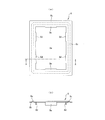
- FIG.4 (a) is a top view of a liquid-tight sealing member
- FIG.4 (b) is A of FIG.4 (a) figure.
- FIG.12 (a) is a top view of a liquid-tight sealing member
- FIG.12 (b) is A of Fig.12 (a) figure FIG.
- FIG. It is the figure which positioned and arrange
- FIG.12 (a) figure FIG.
- FIG.12 (a) figure FIG.
- FIG.12 (a) It is the figure which positioned and arrange
- 3rd Embodiment which concerns on this invention.
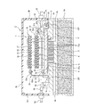
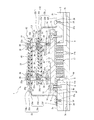
- FIG. 1 to 5 show a power conversion apparatus according to a first embodiment of the present invention.
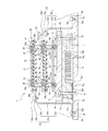
- the power conversion device 1 according to the present embodiment is housed in a housing 2, and the housing 2 sandwiches a cooling body 3 formed of a synthetic resin material and having a water cooling jacket configuration.
- the upper casing 2B is divided into a lower casing 2A and an upper casing 2B.
- the lower housing 2A is a bottomed rectangular tube.
- the lower casing 2A has an open upper portion covered with a cooling body 3, and a smoothing film capacitor 4 is accommodated therein.
- the upper housing 2B includes a rectangular tube 2a having an open upper end and a lower end, and a lid 2b that closes the upper end of the rectangular tube 2a.
- the lower end of the rectangular tube 2a is closed by the cooling body 3.
- a sealing material such as application of a liquid sealant or sandwiching rubber packing is interposed between the lower end of the rectangular tube 2a and the cooling body 3.
- the cooling body 3 is formed, for example, by injection molding aluminum or aluminum alloy having high thermal conductivity, the upper surface is a flat surface, and the cooling water supply port 3 a and the drain port 3 b are located outside the housing 2. It is open.
- the water supply port 3a and the drainage port 3b are connected to a cooling water supply source (not shown) via, for example, a flexible hose.
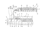
- a dipping portion 5 In the center of the upper surface of the cooling body 3, there is formed a dipping portion 5 that communicates with the water supply port 3a and the drainage port 3b and opens in a rectangular shape.
- a sealing surface 6 is formed.
- the cooling body 3 is formed with an insertion hole 3e through which the positive and negative electrodes 4a covered with insulation of the film capacitor 4 held in the lower housing 2A are vertically inserted.
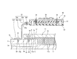
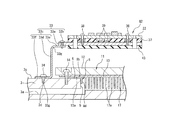
- a power module 11 is joined to the upper portion of the cooling body 3 with a metal packing 7 interposed.
- the power module 11 includes, for example, an insulated gate bipolar transistor (IGBT) as a semiconductor switching element that constitutes, for example, an inverter circuit for power conversion, and incorporates an IGBT in a rectangular parallelepiped insulating case body 12.
- IGBT insulated gate bipolar transistor
- a metal heat dissipating member 13 is formed on the lower surface of the case body 12.
- a liquid contact portion 17 that enters the immersion portion 5 of the cooling body 3 is formed at the center of the lower surface of the heat radiating member 13, and the heat radiating member 13 is cooled by the cooling body 3 by a direct cooling method. . As shown in FIGS.
- the liquid contact portion 17 is composed of a large number of cooling fins 17 a that protrude from the lower surface of the heat radiating member 13 at a predetermined length while being equally spaced from each other.
- a large number of cooling fins 17 a are immersed in the cooling water that has flowed into the immersion part 5.
- a flat heat dissipating member-side seal surface 13a that abuts against 7b is formed.
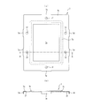
- the metal packing 7 is a member formed by die-drawing a metal plate material, and surrounds a rectangular opening 7a that opens substantially in the same shape as the upper surface opening of the immersion part 5 of the cooling body 3, as shown in FIG.
- the metal packing 7 is arranged so that all the long side outer engagement pieces 7 d and the short side outer engagement pieces 7 e are engaged with the outer surface of the heat radiating member 13.
- the screw through hole 7f corresponds to the insertion hole 15 provided in the module 11 (heat dissipating member 13), and the rectangular frame-shaped seal plate portion 7b surrounds the liquid contact portion 17 of the heat dissipating member 13, while the heat dissipating member 13 It is in contact with the flat heat radiating member side sealing surface 13 a and is positioned and disposed on the heat radiating member 13.
- the fixing screw 14 is inserted into the insertion hole 15 of the heat radiating member 13, and the fixing screw 14 is screwed into the female screw 10 formed in the cooling body 3, whereby the heat radiating member 13 is cooled to the cooling body 3.
- the case body 12 and the heat dissipation member 13 of the power module 11 are formed with insertion holes 15 through which the fixing screws 14 are inserted at the four corners when viewed from the plane.
- substrate fixing portions 16 having a predetermined height are formed to protrude at four locations inside the insertion hole 15.
- a driving circuit board 21 on which a driving circuit for driving an IGBT built in the power module 11 is mounted is fixed to the upper end of the board fixing unit 16.
- a power supply circuit board 23 as a mounting board on which a power supply circuit including a heat generating circuit component for supplying power to the IGBT built in the power module 11 is mounted at a predetermined interval above the drive circuit board 21 is fixed. Yes.
- a mounting in which a control circuit including a heat generating circuit component having a relatively large heat generation amount or a high heat generation density is mounted on the power supply circuit board 23 to control the IGBT built in the power module 11 with a predetermined interval.
- a control circuit board 22 as a board is fixed.
- the drive circuit board 21 is inserted into the insertion hole 21 a formed at a position facing the board fixing part 16, and the male screw part 24 a of the joint screw 24 is inserted, and the male screw part 16 a formed on the upper surface of the board fixing part 16. It is fixed by being screwed onto.
- the power supply circuit board 23 inserts the male screw portion 25a of the joint screw 25 into an insertion hole 22a formed at a position facing the female screw portion 24b formed at the upper end of the joint screw 24, and the male screw portion 25a is inserted into the joint screw 24. It is fixed by being screwed into the female screw portion 24b.
- the control circuit board 22 inserts a fixing screw 26 into an insertion hole 23 a formed at a position opposite to the female screw portion 25 b formed at the upper end of the joint screw 25, and the fixing screw 26 is inserted into the female screw portion 25 b of the joint screw 25. It is fixed by being screwed onto.
- control circuit board 22 and the power circuit board 23 are supported by the heat transfer supporting metal plates 32 and 33 so as to independently form a heat radiation path to the cooling body 3 without going through the housing 2.
- These heat transfer supporting metal plates 32 and 33 are formed of a metal plate having high thermal conductivity, for example, a metal plate made of aluminum or an aluminum alloy.
- the heat transfer support metal plate 32 includes a heat transfer support plate portion 32a on a flat plate and a fixing screw 32b on the right end side of the heat transfer support plate portion 32a along the long side of the power module 11. And a fixed heat transfer support side plate 32c.
- the power supply circuit board 23 is fixed to the heat transfer support plate portion 32 a by a fixing screw 36 via a heat transfer member 35.
- the heat transfer member 35 is an elastic body having elasticity, and has the same outer dimensions as the power circuit board 23. As this heat transfer member 35, a member having improved heat transfer performance while exhibiting insulating performance by interposing a metal filler inside silicon rubber is applied.
- the heat transfer support side plate portion 32c is bent to the left from the upper end of the connection plate portion 32d on the right end side along the long side of the power module 11 and the upper end of the connection plate portion 32d, and is transferred by the fixing screw 32b.
- the upper plate portion 32e is connected to the heat support plate portion 32a, and the lower plate portion 32f is bent to the right from the lower end of the connection plate portion 32d.
- An insertion hole 32g through which the fixing screw 34 is inserted is formed in the lower plate portion 32f of the heat transfer support side plate portion 32c.
- the heat transfer support metal plate 33 includes a heat transfer support plate portion 33a on a flat plate, and a heat transfer support side plate fixed to the left end along the long side of the power module 11 of the heat transfer support plate portion 33a by a fixing screw 33b. Part 33c.
- the control circuit board 22 is fixed to the heat transfer support plate portion 33a by a fixing screw 38 via a heat transfer member 37 similar to the heat transfer member 35 described above.
- the heat transfer support side plate portion 33c is bent to the right from the upper end of the connection plate portion 33d and the connection plate portion 33d extending in the vertical direction on the left end side along the long side of the power module 11, and transferred by the fixing screw 33b.
- the upper plate portion 33e is connected to the heat support plate portion 33a, and the lower plate portion 33f is bent leftward from the lower end of the connection plate portion 33d.
- An insertion hole 33g through which the fixing screw 34 is inserted is formed in the lower plate portion 33f of the heat transfer support side plate portion 33c.
- the heat generating circuit component 39 is mounted on the lower surface side of the control circuit board 22, and the control circuit board 22, the heat transfer member 37, and the heat transfer support plate portion 33 a are stacked by the fixing screw 38.
- the insulating sheet 43 is stuck to the lower surface of the heat transfer support plate portion 33a in order to shorten the insulation distance.
- these stacked components are referred to as a control circuit unit U2.
- the heat generating circuit component 39 mounted on the lower surface side of the control circuit board 22 is embedded in the heat transfer member 37 by the elasticity of the heat transfer member 37.
- the contact between the heat generating circuit component 39 and the heat transfer member 37 is performed without excess and deficiency, and the contact between the heat transfer member 37 and the control circuit board 22 and the heat transfer support plate portion 33a is performed satisfactorily.
- the thermal resistance between the member 37 and the control circuit board 22 and the heat transfer support plate portion 33a can be reduced.
- a heat generating circuit component is also mounted on the lower surface side of the power supply circuit board 23, and the power supply circuit board 23, the heat transfer member 35, and the heat transfer support plate portion 32a are fixed in a stacked state by a fixing screw 36.
- An insulating sheet 42 is attached to the lower surface of the heat transfer support plate portion 32a in order to shorten the insulation distance. Note that these stacked components are referred to as a power supply circuit unit U3.
- the heat generating circuit component mounted on the lower surface side of the power circuit board 23 is embedded in the heat transfer member 35 by the elasticity of the heat transfer member 35.
- the contact between the power circuit board 23 and the heat transfer member 35 is performed without excess and deficiency, and the contact between the heat transfer member 35 and the power circuit board 23 and the heat transfer support plate portion 32a is satisfactorily performed.
- the thermal resistance between the member 35 and the power supply circuit board 23 and the heat transfer support plate portion 32a can be reduced.
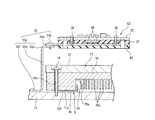
- the fixing screw 14 is inserted into the insertion hole 15 of the heat radiating member 13, and the fixing screw 14 is screwed into the female screw portion formed in the cooling body 3. Further, a plurality of male screw portions 3d are formed on the outer peripheral side plane 3c on the upper surface of the cooling body 3, and through these insertion holes 32g formed in the lower plate portion 32f of the heat transfer supporting metal plate 32, the heat transfer supporting metal plate 3d is transmitted. The insertion hole 33g formed in the lower plate portion 33f of the heat-supporting metal plate 33 is made to correspond. Then, the fixing screw 34 inserted through the insertion holes 32g, 33g is screwed into the male screw portion 3d of the outer peripheral side plane 3c. Thus, the heat transfer support metal plates 32 and 33 are fixed to the cooling body 3 in a state where the lower plate portions 32f and 33f of the heat transfer support metal plates 32 and 33 are in contact with the outer peripheral side plane 3c by surface bonding.
- the bus bar 55 is connected to the positive and negative DC input terminals of the power module 11 at 11 a, and the positive and negative electrodes 4 a of the film capacitor 4 penetrating the cooling body 3 at the other end of the bus bar 55 are fixed screws 51. It is connected with. Further, a crimp terminal 53 fixed to the tip of a connection cord 52 connected to an external converter (not shown) is fixed to the negative electrode terminal 11 a of the power module 11. Further, one end of the bus bar 55 is connected to the three-phase AC output terminal 11 b of the power module 11 with a fixing screw 56, and a current sensor 57 is arranged in the middle of the bus bar 55. A crimp terminal 59 is connected to the other end of the bus bar 55 with a fixing screw 60. The crimp terminal 59 is fixed to a motor connection cable 58 connected to an external three-phase electric motor (not shown).
- DC power is supplied from an external converter (not shown), and the power supply circuit mounted on the power supply circuit board 23 and the control circuit mounted on the control circuit board 22 are set in an operating state.
- a gate signal that is a pulse width modulation signal is supplied to the power module 11 via a drive circuit mounted on the drive circuit board 21.
- the IGBT built in the power module 11 is controlled to convert DC power into AC power.
- the converted AC power is supplied from the three-phase AC output terminal 11b to the motor connection cable 58 via the bus bar 55 to drive and control a three-phase electric motor (not shown).
- the IGBT built in the power module 11 generates heat, but the liquid contact portion 17 provided at the center of the lower surface of the heat radiating member 13 of the power module 11 enters the immersion portion 5 provided in the cooling body 3 and becomes the coolant. Since it is immersed, the power module 11 is efficiently cooled.
- control circuit and the power circuit mounted on the control circuit board 22 and the power circuit board 23 include a heat generating circuit component 39, and the heat generating circuit component 39 generates heat.
- the heat generating circuit component 39 is mounted on the lower surface side of the control circuit board 22 and the power supply circuit board 23.
- heat transfer support plate portions of the heat transfer support metal plates 32 and 33 are provided via heat transfer members 35 and 37 having high thermal conductivity and elasticity. 32a and 33a are provided.
- the heat transmitted to the heat transfer support metal plates 32 and 33 is radiated to the cooling body 3 from the lower plate portions 32f and 33f that are in direct surface contact with the outer peripheral side plane 3c on the upper surface of the cooling body 3, and is supported by the heat transfer. Efficient heat dissipation of the metal plates 32 and 33 is performed.
- the heating element according to the present invention corresponds to the power module 11
- the semiconductor power module according to the present invention corresponds to the power module 11
- the coolant passage according to the present invention corresponds to the immersion part 5.
- the sealing surface of the cooling body corresponds to the cooling body side sealing surface 6, the sealing surface of the heat radiating member according to the present invention corresponds to the heat radiating member side sealing surface 13 a, and the liquid-tight sealing member according to the present invention corresponds to the metal packing 7.
- the engagement piece according to the present invention corresponds to the long side outer engagement piece 7d and the short side outer engagement piece 7e, and the seal portion according to the present invention corresponds to the seal plate part 7b.
- the effect of the power converter of this embodiment is demonstrated.
- the liquid contact portion 17 provided at the center of the lower surface of the heat dissipation member 13 of the power module 11 is immersed in the cooling unit 3. Since it enters and is immersed in the cooling liquid and directly cooled, the power module 11 can be efficiently cooled.
- the lower plate portions 32 f and 33 f of the heat transfer supporting metal plates 32 and 33 are directly surface-bonded to the outer peripheral side plane 3 c on the upper surface of the cooling body 3, the heat transfer is supported from the control circuit board 22 and the power supply circuit board 23.
- the heat transmitted to the heat-supporting metal plates 32 and 33 is radiated from the lower plate portions 32f and 33f to the cooling body 3, so that efficient heat radiation can be performed.
- the sealing plate portion 7b of the metal packing 7 is sandwiched between the cooling body side sealing surface 6 of the cooling body 3 and the heat radiating member side sealing surface 13a of the heat radiating member 13, and is a liquid seal convex portion formed on the sealing plate portion 7b. 7c is crushed by the cooling body side sealing surface 6 and the heat radiating member side sealing surface 13a, so that a reliable liquid-tight sealing of the cooling water accumulated in the immersion part 5 of the cooling body 3 can be secured, and highly reliable power conversion.
- a device 1 can be provided.
- the cooling body 3 of a large and heavy object that is difficult to assemble to a processing machine is not formed with a circumferential groove or the like for mounting an O-ring, but only a flat cooling body side sealing surface 6 is formed. Can be reduced.
- the long side outer engagement piece 7 d of the metal packing 7 is engaged with the outer side surface of the heat dissipation member 13 in the longitudinal direction
- the short side outer engagement piece 7 e is engaged with the outer side surface of the heat dissipation member 13 in the short direction.
- a liquid-tight sealing structure can be obtained with the metal packing 7 formed by die-drawing a metal plate material, and the long side outer engagement piece 7d and the short side for positioning the seal plate portion 7 with a simple configuration. Since the outer engagement piece 7e can be formed, the processing cost of the liquid-tight sealing structure can be reduced.
- FIGS. 6 to 8 show a main part of the power conversion device according to the second embodiment of the present invention.
- the same components as those shown in FIGS. 1 to 5 are denoted by the same reference numerals, and the description thereof is omitted.
- a radiating member 70 made of copper having a rectangular parallelepiped shape with high thermal conductivity is integrally provided on the lower surface of the case body 12.
- a closing member 71 is fixed to the lower surface.
- the heat radiating member 70 is formed with a cooling chamber 70a that opens in a rectangular shape at the center of the lower surface of the heat radiating member 70, and the water supply of a water supply path 70b formed inside the heat radiating member 70 on one wall portion in the longitudinal direction of the cooling chamber 70a.
- a mouth is opened, and a drainage port of a drainage channel 70c formed inside the heat radiating member 70 is opened on the other wall portion in the longitudinal direction of the cooling chamber 70a.
- the water supply channel 70b and the drainage channel 70c are connected to a cooling water supply source (not shown) via a flexible hose, for example.
- the closing member 71 is a member that closes the open upper portion of the lower housing 2A in which the smoothing film capacitor 4 is housed, like the cooling body 3 of the first embodiment.
- aluminum having a high thermal conductivity It is formed by injection molding of an aluminum alloy.
- a metal is provided between the heat radiating member side seal surface 70 f of the heat radiating member 70 and the upper surface of the closing member 71.
- a seal plate portion 7b of the packing 7 is interposed.
- the metal packing 7 is the same as the structure shown in FIG. 4 of the first embodiment.
- the upper surface where the sealing plate portion 7b of the metal packing 7 of the closing member 71 is in surface contact is formed as a flat closing member side sealing surface 71a.
- the heat dissipating member 70 is arranged so that the flat heat dissipating member side seal surface 70f faces upward, and the long side outer engaging piece 7d and the short side outer engaging piece 7e are engaged with the outer surface of the heat dissipating member 70.
- the metal packing 7 is disposed. Accordingly, the screw through hole 7f corresponds to the insertion hole 15 provided in the heat radiating member 70, the square frame-shaped seal plate portion 7b contacts the heat radiating member side seal surface 70f, and the metal packing 7 is positioned on the heat radiating member 70. To be placed.
- the fixing screw 14 is inserted into the insertion hole 15 formed in the case body 12 and the heat radiating member 70 from below, and the fixing screw 14 is screwed into the female screw portion 71 b formed in the closing member 71 to close the heat radiating member 70.
- the member 71 is fixed.
- the liquid seal convex portion 7c formed on the seal plate portion 7b of the metal packing 7 is sandwiched between the heat radiating member side sealing surface 70f of the heat radiating member 70 and the closing member side sealing surface 71a of the closing member 71 and is crushed and cooled. Liquid-tight sealing is performed to prevent the cooling water accumulated in the chamber 70a from leaking outside.
- the heating element according to the present invention corresponds to the power module 11
- the semiconductor power module according to the present invention corresponds to the power module 11
- the coolant passage according to the present invention corresponds to the cooling chamber 70a.
- the sealing surface of the heat radiating member corresponds to the heat radiating member side sealing surface 70f
- the sealing surface of the closing member according to the present invention corresponds to the closing member side sealing surface 71a
- the liquid tight sealing member according to the present invention corresponds to the metal packing 7.
- the engagement piece of the metal packing according to the present invention corresponds to the long side outer engagement piece 7d and the short side outer engagement piece 7e
- the seal portion according to the present invention corresponds to the seal plate portion 7b.
- the effect of the power converter device of this embodiment is demonstrated.
- the coolant flows into the cooling chamber 70a provided at the center of the lower surface of the heat dissipation member 70 of the power module 11, and directly cools the heat dissipation member 70. Therefore, the power module 11 can be efficiently cooled.
- the heat transfer support metal plates 32 and 33 are directly surface-bonded to the upper surface of the closing member 71, the heat transfer support metal plates are supplied from the control circuit board 22 and the power supply circuit board 23. The heat transmitted to 32 and 33 is radiated from the lower plate portions 32f and 33f to the closing member 71, so that efficient heat radiation can be performed.
- the sealing plate portion 7b of the metal packing 7 is sandwiched between the heat radiating member side sealing surface 70f of the heat radiating member 70 and the closing member side sealing surface 71a of the closing member 71, and is formed on the sealing plate portion 7b.
- the portion 7c is crushed by the heat radiating member side sealing surface 70f and the closing member side sealing surface 71a, so that a reliable liquid-tight sealing of the cooling water accumulated in the cooling chamber 70a can be secured, and the highly reliable power conversion device 1 Can be provided.
- the peripheral groove for mounting the O-ring is not formed on both the heat radiating member 70 and the closing member 71, and only the flat heat radiating member side sealing surface 70f and the closing member side sealing surface 71a are formed. Can be reduced.
- the long side outer engagement piece 7 d of the metal packing 7 is engaged with the outer side surface of the long side of the heat radiating member 70, and the short side outer engagement piece 7 e of the metal packing 7 is connected to the outer side surface of the short side of the heat radiating member 70.
- the metal packing 7 is prevented from being detached from the heat radiating member 70, and the assembly efficiency can be improved.
- the metal packing 7 is a member formed by die-drawing a metal plate material, the manufacturing cost of the metal packing 7 can be reduced.
- FIG. 9 to 14 show a power converter according to a third embodiment of the present invention.
- symbol is attached
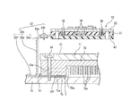
- a metal packing 8 is disposed on the upper surface of the cooling body 3.
- the metal packing 8 is a member formed by die-drawing a metal plate material. As shown in FIG. 12A, a rectangular opening 8a having substantially the same shape as the upper surface opening of the immersion part 5 of the cooling body 3 is used.
- a rectangular frame-shaped sealing plate portion 8b formed so as to surround the end plate, and an endless annular liquid-sealing convex portion 8c that is continuously formed on the entire circumference of the sealing plate portion 8b and protrudes in a curved shape in one of the plate thickness directions.
- a plurality of long-side inner engagement pieces 8 d extending in a direction orthogonal to the surface direction of the seal plate portion 8 b from the side edge of the long side opening 8 a of the seal plate portion 8 b, and the seal plate portion 8 b
- a plurality of short side inner engagement pieces 8e extending from the side edge of the short side opening 8a in the direction orthogonal to the surface direction of the seal plate portion 8b in the same direction as the long side inner engagement piece 8d.
- the metal packing 8 has a rectangular shape by engaging all the long side inner engagement pieces 8 d and the short side inner engagement pieces 8 e with the upper surface opening of the immersion part 5 of the cooling body 3.
- the frame-shaped seal plate portion 8 b is positioned on the cooling body 3 in a state where the frame-shaped seal plate portion 8 b is in contact with the flat cooling body side sealing surface 6 on the periphery of the immersion portion 5.
- a power module 11 is joined to the upper part of the cooling body 3.
- the power module 11 includes, for example, an insulated gate bipolar transistor (IGBT) as a semiconductor switching element that constitutes, for example, an inverter circuit for power conversion, and incorporates an IGBT in a rectangular parallelepiped insulating case body 12.
- IGBT insulated gate bipolar transistor
- a metal heat dissipating member 13 is formed on the lower surface of the case body 12.
- a liquid contact portion 17 that enters the immersion portion 5 of the cooling body 3 is formed at the center of the lower surface of the heat radiating member 13, and the heat radiating member 13 is cooled by the cooling body 3 by a direct cooling method. .
- the liquid contact part 17 is composed of a large number of cooling fins 17a protruding from the lower surface of the heat radiating member 13 at a predetermined length while being equally spaced from each other, and the cooling water flowing into the immersion part 5 from the water supply port 3a. In addition, a large number of cooling fins 17a are immersed.
- a side seal surface 13a is formed.
- the case body 12 and the heat radiating member 13 of the power module 11 are formed with insertion holes 15 through which the fixing screws 14 are inserted at the four corners when viewed from the plane.
- substrate fixing portions 16 having a predetermined height are formed to protrude at four locations inside the insertion hole 15.
- a driving circuit board 21 on which a driving circuit for driving an IGBT built in the power module 11 is mounted is fixed to the upper end of the board fixing unit 16.
- a power supply circuit board 23 as a mounting board on which a power supply circuit including a heat generating circuit component for supplying power to the IGBT built in the power module 11 is mounted at a predetermined interval above the drive circuit board 21 is fixed.
- a mounting in which a control circuit including a heat generating circuit component having a relatively large heat generation amount or a high heat generation density is mounted on the power supply circuit board 23 to control the IGBT built in the power module 11 with a predetermined interval.
- a control circuit board 22 as a board is fixed.
- the drive circuit board 21 is inserted into the insertion hole 21 a formed at a position facing the board fixing part 16, and the male screw part 24 a of the joint screw 24 is inserted, and the male screw part 16 a formed on the upper surface of the board fixing part 16. It is fixed by being screwed onto.
- the power supply circuit board 23 inserts the male screw portion 25a of the joint screw 25 into an insertion hole 22a formed at a position facing the female screw portion 24b formed at the upper end of the joint screw 24, and the male screw portion 25a is inserted into the joint screw 24. It is fixed by being screwed into the female screw portion 24b.
- the control circuit board 22 inserts a fixing screw 26 into an insertion hole 23 a formed at a position opposite to the female screw portion 25 b formed at the upper end of the joint screw 25, and the fixing screw 26 is inserted into the female screw portion 25 b of the joint screw 25. It is fixed by being screwed onto.
- control circuit board 22 and the power circuit board 23 are supported by the heat transfer supporting metal plates 32 and 33 so as to independently form a heat radiation path to the cooling body 3 without going through the housing 2.
- These heat transfer supporting metal plates 32 and 33 are formed of a metal plate having high thermal conductivity, for example, a metal plate made of aluminum or an aluminum alloy.
- the heat transfer support metal plate 32 has a heat transfer support plate portion 32a on a flat plate and a fixing screw 32b on the right end side along the long side of the power module 11 of the heat transfer support plate portion 32a. And a fixed heat transfer support side plate 32c.
- the power supply circuit board 23 is fixed to the heat transfer support plate portion 32 a by a fixing screw 36 via a heat transfer member 35.
- the heat transfer member 35 is an elastic body having elasticity, and has the same outer dimensions as the power circuit board 23. As this heat transfer member 35, a member having improved heat transfer performance while exhibiting insulating performance by interposing a metal filler inside silicon rubber is applied.
- the heat transfer support side plate portion 32c is bent to the left from the upper end of the connection plate portion 32d on the right end side along the long side of the power module 11 and the upper end of the connection plate portion 32d, and is transferred by the fixing screw 32b.
- the upper plate portion 32e is connected to the heat support plate portion 32a, and the lower plate portion 32f is bent to the right from the lower end of the connection plate portion 32d.
- An insertion hole 32g through which the fixing screw 34 is inserted is formed in the lower plate portion 32f of the heat transfer support side plate portion 32c.
- the heat transfer support metal plate 33 includes a heat transfer support plate portion 33a on a flat plate, and a heat transfer support side plate fixed to the left end along the long side of the power module 11 of the heat transfer support plate portion 33a by a fixing screw 33b. Part 33c.
- the control circuit board 22 is fixed to the heat transfer support plate portion 33a by a fixing screw 38 via a heat transfer member 37 similar to the heat transfer member 35 described above.
- the heat transfer support side plate portion 33c is bent to the right from the upper end of the connection plate portion 33d and the connection plate portion 33d extending in the vertical direction on the left end side along the long side of the power module 11, and transferred by the fixing screw 33b.
- the upper plate portion 33e is connected to the heat support plate portion 33a, and the lower plate portion 33f is bent leftward from the lower end of the connection plate portion 33d.
- An insertion hole 33g through which the fixing screw 34 is inserted is formed in the lower plate portion 33f of the heat transfer support side plate portion 33c.
- the heat generating circuit component 39 is mounted on the lower surface side of the control circuit board 22, and the control circuit board 22, the heat transfer member 37, and the heat transfer support plate portion 33 a are stacked by the fixing screw 38.
- the insulating sheet 43 is stuck to the lower surface of the heat transfer support plate portion 33a in order to shorten the insulation distance. Note that these stacked components are referred to as a control circuit unit U2.
- the heat generating circuit component 39 mounted on the lower surface side of the control circuit board 22 is embedded in the heat transfer member 37 by the elasticity of the heat transfer member 37. For this reason, the contact between the heat generating circuit component 39 and the heat transfer member 37 is performed without excess and deficiency, and the contact between the heat transfer member 37 and the control circuit board 22 and the heat transfer support plate portion 33a is performed satisfactorily. The thermal resistance between the member 37 and the control circuit board 22 and the heat transfer support plate portion 33a can be reduced.
- a heat generating circuit component is also mounted on the lower surface side of the power supply circuit board 23, and the power supply circuit board 23, the heat transfer member 35, and the heat transfer support plate portion 32a are fixed in a stacked state by a fixing screw 36.
- An insulating sheet 42 is attached to the lower surface of the heat transfer support plate portion 32a in order to shorten the insulation distance. Note that these stacked components are referred to as a power supply circuit unit U3.
- the heat generating circuit component mounted on the lower surface side of the power circuit board 23 is embedded in the heat transfer member 35 by the elasticity of the heat transfer member 35.
- the contact between the power circuit board 23 and the heat transfer member 35 is performed without excess and deficiency, and the contact between the heat transfer member 35 and the power circuit board 23 and the heat transfer support plate portion 32a is satisfactorily performed.
- the thermal resistance between the member 35 and the power supply circuit board 23 and the heat transfer support plate portion 32a can be reduced.
- the fixing screw 14 is inserted into the insertion hole 15 of the heat radiating member 13, and the fixing screw 14 is screwed into the female screw portion formed in the cooling body 3. Further, a plurality of male screw portions 3d are formed on the outer peripheral side plane 3c on the upper surface of the cooling body 3, and through these insertion holes 32g formed in the lower plate portion 32f of the heat transfer supporting metal plate 32, the heat transfer supporting metal plate 3d is transmitted. The insertion hole 33g formed in the lower plate portion 33f of the heat-supporting metal plate 33 is made to correspond. Then, the fixing screw 34 inserted through the insertion holes 32g, 33g is screwed into the male screw portion 3d of the outer peripheral side plane 3c.
- the heat radiation member 13 is fixed to the cooling body 3, and the liquid seal projection 8 c formed on the seal plate portion 8 b of the metal packing 8 disposed around the immersion portion 5 of the cooling body 3 is the cooling body side sealing surface. 6 and the heat radiating member side seal surface 13a are crushed and crushed, and a liquid-tight seal is provided to prevent the coolant accumulated in the immersion part 5 of the cooling body 3 from leaking to the outside, and the seal plate part 8b is cooled.
- the power module 11 is fixed to the cooling body 3 in a state in which the body-side sealing surface 6 and the heat radiation member-side sealing surface 13a are in contact with each other by surface bonding. Further, the heat transfer support metal plates 32 and 33 are fixed to the cooling body 3 in a state where the lower plate portions 32f and 33f of the heat transfer support metal plates 32 and 33 are in contact with the outer peripheral side plane 3c by surface bonding. .
- the bus bar 55 is connected to the positive and negative DC input terminals of the power module 11 at 11 a, and the positive and negative electrodes 4 a of the film capacitor 4 penetrating the cooling body 3 at the other end of the bus bar 55 are fixed screws 51. It is connected with. Further, a crimp terminal 53 fixed to the tip of a connection cord 52 connected to an external converter (not shown) is fixed to the negative electrode terminal 11 a of the power module 11. Further, one end of the bus bar 55 is connected to the three-phase AC output terminal 11 b of the power module 11 with a fixing screw 56, and a current sensor 57 is arranged in the middle of the bus bar 55. A crimp terminal 59 is connected to the other end of the bus bar 55 with a fixing screw 60. The crimp terminal 59 is fixed to a motor connection cable 58 connected to an external three-phase electric motor (not shown).
- DC power is supplied from an external converter (not shown), and the power supply circuit mounted on the power supply circuit board 23 and the control circuit mounted on the control circuit board 22 are set in an operating state.
- a gate signal that is a pulse width modulation signal is supplied to the power module 11 via a drive circuit mounted on the drive circuit board 21.
- the IGBT built in the power module 11 is controlled to convert DC power into AC power.
- the converted AC power is supplied from the three-phase AC output terminal 11b to the motor connection cable 58 via the bus bar 55 to drive and control a three-phase electric motor (not shown).
- the IGBT built in the power module 11 generates heat, but the liquid contact portion 17 provided at the center of the lower surface of the heat radiating member 13 of the power module 11 enters the immersion portion 5 provided in the cooling body 3 and becomes the coolant. Since it is immersed, the power module 11 is efficiently cooled.
- control circuit and the power circuit mounted on the control circuit board 22 and the power circuit board 23 include a heat generating circuit component 39, and the heat generating circuit component 39 generates heat.
- the heat generating circuit component 39 is mounted on the lower surface side of the control circuit board 22 and the power supply circuit board 23.
- heat transfer support plate portions of the heat transfer support metal plates 32 and 33 are provided via heat transfer members 35 and 37 having high thermal conductivity and elasticity. 32a and 33a are provided.
- the heat transmitted to the heat transfer support metal plates 32 and 33 is radiated to the cooling body 3 from the lower plate portions 32f and 33f that are in direct surface contact with the outer peripheral side plane 3c on the upper surface of the cooling body 3, and is supported by the heat transfer. Efficient heat dissipation of the metal plates 32 and 33 is performed.
- the heating element according to the present invention corresponds to the power module 11
- the semiconductor power module according to the present invention corresponds to the power module 11
- the coolant passage according to the present invention corresponds to the immersion part 5.
- the sealing surface of the cooling body corresponds to the cooling body side sealing surface 6
- the sealing surface of the heat radiating member according to the present invention corresponds to the heat radiating member side sealing surface 13 a
- the liquid-tight sealing member according to the present invention corresponds to the metal packing 8.
- the engagement piece according to the present invention corresponds to the long side inner engagement piece 8d and the short side inner engagement piece 8e
- the seal portion according to the present invention corresponds to the seal plate part 8b.
- the effect of the power converter device of this embodiment is demonstrated.
- the liquid contact portion 17 provided in the center of the lower surface of the heat dissipation member 13 of the power module 11 is immersed in the cooling unit 3. Since it enters and is immersed in the cooling liquid and directly cooled, the power module 11 can be efficiently cooled.
- the lower plate portions 32 f and 33 f of the heat transfer supporting metal plates 32 and 33 are directly surface-bonded to the outer peripheral side plane 3 c on the upper surface of the cooling body 3, the heat transfer is supported from the control circuit board 22 and the power supply circuit board 23. The heat transmitted to the heat-supporting metal plates 32 and 33 is radiated from the lower plate portions 32f and 33f to the cooling body 3, so that efficient heat radiation can be performed.
- the sealing plate portion 8b of the metal packing 8 is sandwiched between the cooling body side sealing surface 6 of the cooling body 3 and the heat radiating member side sealing surface 13a of the heat radiating member 13, and is a liquid seal convex portion formed on the sealing plate portion 8b. 8c is crushed by the cooling body side sealing surface 6 and the heat radiating member side sealing surface 13a, so that a reliable liquid-tight sealing of the cooling water accumulated in the immersion part 5 of the cooling body 3 can be secured, and highly reliable power conversion.
- a device 1 can be provided.
- the cooling body 3 of a large and heavy object that is difficult to assemble to a processing machine is not formed with a circumferential groove or the like for mounting an O-ring, but only a flat cooling body side sealing surface 6 is formed. Can be reduced.
- the metal packing 8 is a member formed by die-drawing a metal plate material, the manufacturing cost of the metal packing 8 can be reduced.
- FIG. 14 shows a modification of the above-described power conversion device of the third embodiment.
- the heat transfer supporting metal plate 33 that supports the control circuit board 22 of this modification includes a lower plate portion 33h that is bent to the right from the lower end of the connecting plate portion 33d, as compared with the first embodiment.
- the lower plate portion 33h is formed with an insertion hole 33i through which the fixing screw 14 is inserted.
- the heat transfer support metal plate 32 that supports the control circuit board 22 of the present modification also includes a lower plate portion (not shown) bent leftward from the lower end of the connecting plate portion 32d.
- an insertion hole for inserting the fixing screw 14 is formed in the lower plate portion.
- FIGS. 15 to 17 show a main part of the power conversion device according to the fourth embodiment of the present invention.
- the power module 11 according to the present embodiment is provided with a rectangular parallelepiped heat dissipation member 70 made of copper having a high thermal conductivity on the lower surface of the case body 12.
- a closing member 71 is fixed to the lower surface.
- the heat radiating member 70 is formed with a cooling chamber 70a that opens in a rectangular shape at the center of the lower surface of the heat radiating member 70, and the water supply of a water supply path 70b formed inside the heat radiating member 70 on one wall portion in the longitudinal direction of the cooling chamber 70a.
- a mouth is opened, and a drainage port of a drainage channel 70c formed inside the heat radiating member 70 is opened on the other wall portion in the longitudinal direction of the cooling chamber 70a.
- the water supply channel 70b and the drainage channel 70c are connected to a cooling water supply source (not shown) via a flexible hose, for example.
- the closing member 71 is a member that closes the open upper portion of the lower housing 2A in which the smoothing film capacitor 4 is housed, like the cooling body 3 of the third embodiment.
- aluminum having a high thermal conductivity It is formed by injection molding of an aluminum alloy.
- a metal is provided between the heat radiating member side seal surface 70 f of the heat radiating member 70 and the upper surface of the closing member 71.
- a seal plate portion 8b of the packing 8 is interposed.
- the metal packing 8 is the same as the structure shown in FIG. 12 of the third embodiment.
- the upper surface where the sealing plate portion 8b of the metal packing 8 of the closing member 71 is in surface contact is formed as a flat closing member side sealing surface 71a.
- the heat dissipating member 70 is arranged so that the flat heat dissipating member-side seal surface 70f faces upward, and all the long side inner engagement pieces 8d and the short side inner engagements are formed on the opening periphery of the cooling chamber 70a of the heat dissipating member 70.
- the metal packing 8 is arranged so that the joining piece 8e is engaged. As a result, the metal packing 8 is positioned with the square frame-shaped seal plate portion 8b evenly contacting the flat heat radiation member side seal surface 70f on the periphery of the opening of the cooling chamber 70a.
- the fixing screw 14 is inserted into the insertion hole 15 formed in the case body 12 and the heat radiating member 70 from below, and the fixing screw 14 is screwed into the female screw portion 71 b formed in the closing member 71 to close the heat radiating member 70.
- the member 71 is fixed.
- the liquid seal convex portion 8c formed on the seal plate portion 8b of the metal packing 8 is sandwiched between the heat radiating member side seal surface 70f of the heat radiating member 70 and the closing member side seal surface 71a of the occluding member 71, and is crushed. Liquid-tight sealing is performed to prevent the cooling water accumulated in the chamber 70a from leaking outside.
- the heating element according to the present invention corresponds to the power module 11
- the semiconductor power module according to the present invention corresponds to the power module 11
- the coolant passage according to the present invention corresponds to the cooling chamber 70a.
- the sealing surface of the heat radiating member corresponds to the heat radiating member side sealing surface 70f
- the sealing surface of the closing member according to the present invention corresponds to the closing member side sealing surface 71a
- the liquid tight sealing member according to the present invention corresponds to the metal packing 8.
- the engagement piece according to the present invention corresponds to the long side inner engagement piece 8d and the short side inner engagement piece 8e
- the seal portion according to the present invention corresponds to the seal plate part 8b.
- the effect of the power converter device of this embodiment is demonstrated.
- the coolant flows into the cooling chamber 70a provided at the center of the lower surface of the heat dissipation member 70 of the power module 11, and directly cools the heat dissipation member 70. Therefore, the power module 11 can be efficiently cooled.
- the heat transfer support metal plates 32 and 33 are directly surface-bonded to the upper surface of the closing member 71, the heat transfer support metal plates are supplied from the control circuit board 22 and the power supply circuit board 23.
- the heat transmitted to 32 and 33 is radiated from the lower plate portions 32f and 33f to the closing member 71, so that efficient heat radiation can be performed.
- the sealing plate portion 8b of the metal packing 8 is sandwiched between the heat radiating member side sealing surface 70f of the heat radiating member 70 and the closing member side sealing surface 71a of the closing member 71, and is formed on the sealing plate portion 8b.
- the portion 8c is crushed by the heat radiating member side sealing surface 70f and the closing member side sealing surface 71a, so that a reliable liquid-tight sealing of the cooling water accumulated in the cooling chamber 70a can be secured, and the highly reliable power conversion device 1 Can be provided.
- peripheral groove for mounting the O-ring is not formed on both the heat radiating member 70 and the closing member 71, and only the flat heat radiating member side sealing surface 70f and the closing member side sealing surface 71a are formed. Can be reduced. Further, all the long side inner engagement pieces 8 d and the short side inner engagement pieces 8 e of the metal packing 8 are engaged with the opening peripheral edge of the cooling chamber 70 a formed in the heat radiation member 70, so that the heat radiation member of the heat radiation member 70.
- the positioning of the seal plate portion 8b with respect to the side seal surface 70f can be easily performed, and before the liquid seal convex portion 8c of the seal plate portion 8b is crushed by the heat radiating member side seal surface 70f and the closing member side seal surface 71a, It is possible to prevent the metal packing 8 from coming off from the heat radiating member 70 and to improve the assembly efficiency.
- the metal packing 8 is a member formed by die-drawing a metal plate material, the manufacturing cost of the metal packing 8 can be reduced.
- the heat transfer supporting metal plate 33 that supports the control circuit board 22 is bent rightward from the lower end of the connecting plate portion 33d.
- the heat transfer supporting metal plate 32 which supports the control circuit board 22 as the lower plate portion is also a lower plate portion bent leftward from the lower end of the connecting plate portion 32d, and the heat dissipating member 13 and the cooling body are fixed by the fixing screws 14.
- the heat transfer clamping member 33 and the heat transfer support metal plate 32 are fixed to the cooling body, and at the same time, the liquid seal convex portion 8c formed on the seal plate portion 8b of the metal packing 8 is crushed, and the cooling body 3 is provided with a liquid-tight seal of the cooling water accumulated in the immersion part 5, so that the assembly efficiency can be further improved.
- FIGS. 18 to 21 show a main part of a power conversion device according to a fifth embodiment of the present invention.
- the cooling body 3 and the power module 11 (the case body 12 and the heat radiating member 13) of the present embodiment have the same structure as that of the first embodiment described above, and the upper surface of the cooling body 3 and the power module.
- the metal packing 9 is interposed between the lower surface of the heat radiating member 13 of the eleventh member.
- the metal packing 9 of the present embodiment is a member formed by drawing a metal plate material, and as shown in FIG. 20, a rectangular opening that is substantially the same shape as the upper surface opening of the immersion part 5 of the cooling body 3.
- a plurality of short side inner engagement pieces 9e extending from the side edge of the short side opening 9a in the direction perpendicular to the surface direction of the seal plate portion 8b in the same direction as the long side inner engagement piece 9d; Opposite to the direction in which the long side inner engagement piece 9d extends from the outer peripheral edge of the long side of the seal plate portion 9b
- a plurality of long side outer engagement pieces 9f extending in a direction orthogonal to the surface direction of the seal
- the metal packing 9 is arranged so that all the long side inner engagement pieces 9 d and the short side inner engagement pieces 8 e are engaged with the upper surface opening of the immersion part 5 of the cooling body 3.
- the screw through hole 9h corresponds to the female screw 10 provided in the cooling body 3, and the square frame-shaped sealing plate portion 9b is in contact with the flat cooling body side sealing surface 6 at the periphery of the immersion portion 5.
- the cooling body 3 is positioned and arranged.
- the power module 11 is arranged so that all the long side outer engagement pieces 9f and the short side outer engagement pieces 9g of the metal packing 9 are engaged with the outer surface of the heat radiating member 13, whereby the power module 11 is inserted.
- the hole 15 corresponds to the female screw 10 through the screw through hole 9h, and the cooling fin 17a of the heat radiating member 13 enters the center of the immersion part 5 of the cooling body 3, and the metal packing 9 of the present embodiment is cooled
- the power module 11 is positioned with respect to the body 3.
- the fixing screw 14 is inserted into the insertion hole 15 of the heat radiating member 13, and the fixing screw 14 is screwed into the female screw 10 formed in the cooling body 3, so that the heat radiating member 13 is cooled to the cooling body 3.
- the liquid seal projection 9c formed on the seal plate portion 9b of the metal packing 9 disposed around the immersion portion 5 of the cooling body 3 is sandwiched between the cooling body side sealing surface 6 and the heat radiating member side sealing surface 13a. Then, the liquid is sealed (see FIG. 18), and liquid-tight sealing is performed to prevent the cooling water accumulated in the immersion part 5 of the cooling body 3 from leaking to the outside.
- the heating element according to the present invention corresponds to the power module 11
- the semiconductor power module according to the present invention corresponds to the power module 11
- the coolant passage according to the present invention corresponds to the immersion part 5.
- the sealing surface of the cooling body corresponds to the cooling body side sealing surface 6
- the sealing surface of the heat radiating member according to the present invention corresponds to the heat radiating member side sealing surface 13 a
- the liquid-tight sealing member according to the present invention corresponds to the metal packing 9.
- the engagement piece according to the present invention corresponds to the long side inner engagement piece 9d and the short side inner engagement piece 9e
- the seal portion according to the present invention corresponds to the seal plate part 9b.
- the seal plate portion 9b of the metal packing 9 is sandwiched between the cooling body side seal surface 6 of the cooling body 3 and the heat dissipation member side seal surface 13a of the heat dissipation member 13, and the seal plate portion
- the liquid seal convex part 9c formed in 9b is crushed by the cooling body side sealing surface 6 and the heat radiating member side sealing surface 13a, and it is possible to ensure a reliable liquid tight sealing of the cooling water accumulated in the immersion part 5 of the cooling body 3.
- the power converter device 1 can be provided with high reliability.
- the cooling body 3 of a large and heavy object that is difficult to be assembled in a processing machine is not formed with a circumferential groove or the like for mounting an O-ring, and a flat cooling body side sealing surface 6 is formed. Therefore, the processing cost can be reduced.
- the long side inner engagement piece 9d and the short side inner engagement piece 9e of the metal packing 9 are engaged with the upper surface opening of the immersion part 5, whereby the seal plate part 8b with respect to the cooling body side sealing surface 6 of the cooling body 3 is provided.
- the metal packing 9 is detached from the cooling body 3 before the liquid seal projection 9c of the sealing plate portion 9b is crushed by the cooling body side sealing surface 6 and the heat radiating member side sealing surface 13a. Can be prevented, and the assembly efficiency can be improved.
- the metal packing 9 is a member formed by drawing a metal plate material, the manufacturing cost of the metal packing 9 can be reduced.
- the present invention is not limited to the above-described configuration, and the heat transfer members 35 and 37 may be provided only where the heat generating circuit component 39 exists. Further, in each of the above-described embodiments, the case where the heat generating circuit component 39 is mounted on the heat transfer members 35 and 37 on the back surface side using the control circuit board 22 and the power supply circuit board 23 has been described. However, the present invention is not limited to the above configuration. That is, the heat generating circuit component 39 may be mounted on the outer peripheral area of the control circuit board 22 and the power supply circuit board 23 on the opposite side to the heat transfer members 35 and 37.
- the heat-transfer support plate part 32a and the heat-transfer support side plate part 32c which comprise the heat-transfer support metal plate 32 are another member, and the heat-transfer support plate which comprises the heat-transfer support metal plate 33
- the portion 33a and the heat transfer support side plate portion 33c are configured as separate members.
- the cooling efficiency of the power supply circuit unit U3 is improved and the heat transfer support is configured.
- the plate portion 33a and the heat transfer support side plate portion 33c are integrated members, the cooling efficiency of the control circuit unit U2 can be improved.
- the present invention is not limited to this, and a cylindrical electrolytic capacitor may be applied.
- the power converter device 1 which concerns on this invention can be applied to the electric vehicle or the rail vehicle which drive
- the power conversion device 1 is not limited to an electrically driven vehicle, and the power conversion device 1 of the present invention can be applied when driving an actuator such as an electric motor in other industrial equipment.
- the cooling structure according to the present invention is useful for reducing the processing cost and improving the assembly efficiency.
- SYMBOLS 1 Power converter device, 2 ... Housing
- Heat radiation member, 13a Heat radiation member side sealing surface, 15 ... Insertion hole, 16 ... Board fixing
- Insulating sheet 52 ... Connection cord, 53 ... Crimp terminal, 55 ... Bus bar, 57 ... Current sensor, 58 ... Motor connection cable, 59 ... Crimp terminal, 70 ... Heat radiation member, 70a ... Cooling chamber, 70b ... Water supply channel, 7 c ... drainage, 70d ... bottom, 70e ... cooling fins, 70f ... heat radiating member side sealing surface, 71 ... closing member, 71a ... closing member side sealing surface, U2 ... control circuit unit, U3 ... power supply circuit unit
Landscapes
- Engineering & Computer Science (AREA)
- Microelectronics & Electronic Packaging (AREA)
- Physics & Mathematics (AREA)
- Thermal Sciences (AREA)
- Power Engineering (AREA)
- Cooling Or The Like Of Semiconductors Or Solid State Devices (AREA)
- Inverter Devices (AREA)
Abstract
一面に放熱部材(13)が形成された半導体パワーモジュール(11)と、放熱部材に接合される冷却体(3)とを有し、冷却体は、放熱体に接合する側に開口して形成され、冷却液を通流する冷却液通路(5)を備え、放熱部材は、冷却体に接合する側に冷却液通路に挿入配置する接液部(17)が突出して形成されている。冷却体と放熱部材との間に液密封止部材(7)が配置されている。この液密封止部材は、冷却体及び放熱部材の間に密着するシール部(7b)と、放熱部材の外側面に係合してシール部の位置決めをする位置決め部(7d)とを有している。そして、シール部が密着する冷却体及び放熱部材のシール面(6),(13a)は、平坦面に形成されている。
Description
本発明は、発熱体の熱を冷却する冷却構造体と、電力変換用の半導体スイッチング素子を内蔵したモジュール上に、所定間隔を保って上記半導体スイッチング素子を駆動する発熱回路部品を含む回路部品を実装した実装基板を支持するようにした電力変換装置に関する。
この種の電力変換装置としては、特許文献1に記載された電力変換装置が知られている。
この電力変換装置は、筐体内に、冷却液が通過する冷却ジャケットを配置し、この冷却ジャケット上に電力変換用の半導体スイッチング素子としてのIGBTを内蔵したパワーモジュールを配置している。この電力変換装置の冷却ジャケットには、パワーモジュールに接合する側に開口して冷却液が通流する浸漬部が設けられており、パワーモジュールに、水冷ジャケット側に突出して浸漬部に浸漬する接液部を設けることで、直接冷却方式の電力変換装置としている。
この直接冷却方式の電力変換装置は、パワーモジュール及び水冷ジャケットの接合面の一方に周溝を形成し、その周溝にOリングを装着し、接合面同士でOリングを押しつぶすことで液密封止構造としている。
この電力変換装置は、筐体内に、冷却液が通過する冷却ジャケットを配置し、この冷却ジャケット上に電力変換用の半導体スイッチング素子としてのIGBTを内蔵したパワーモジュールを配置している。この電力変換装置の冷却ジャケットには、パワーモジュールに接合する側に開口して冷却液が通流する浸漬部が設けられており、パワーモジュールに、水冷ジャケット側に突出して浸漬部に浸漬する接液部を設けることで、直接冷却方式の電力変換装置としている。
この直接冷却方式の電力変換装置は、パワーモジュール及び水冷ジャケットの接合面の一方に周溝を形成し、その周溝にOリングを装着し、接合面同士でOリングを押しつぶすことで液密封止構造としている。
しかし、上述した液密封止構造において、冷却ジャケットの接合面にOリング装着用の周溝を形成する作業は、大型重量物である冷却ジャケットを加工機械に組付ける際の取り扱いが困難なので、加工コストが増大するおそれがある。
また、周溝に装着したOリングが、パワーモジュール及び水冷ジャケットの接合面により押しつぶされる前に、周溝から抜け出るおそれがあり、組立効率の面で問題がある。
本発明は、上記従来例の未解決の課題に着目してなされたものであり、加工コストの低減化を図るとともに、組立効率を向上させることができる冷却構造体及び電力変換装置を提供することを目的としている。
また、周溝に装着したOリングが、パワーモジュール及び水冷ジャケットの接合面により押しつぶされる前に、周溝から抜け出るおそれがあり、組立効率の面で問題がある。
本発明は、上記従来例の未解決の課題に着目してなされたものであり、加工コストの低減化を図るとともに、組立効率を向上させることができる冷却構造体及び電力変換装置を提供することを目的としている。
上記目的を達成するために、本発明の一態様に係る冷却構造体は、一面に放熱部材が形成された発熱体と、放熱部材に接合される冷却体と、を備え、冷却体は、冷却液を通流する冷却液通路が放熱体に接合する側に開口して形成され、放熱部材は、冷却体に接合する側に冷却液通路に挿入配置する接液部が突出して形成され、冷却液通路を液密封止する液密封止部材が配置されており、液密封止部材は、冷却体及び放熱部材の間に密着するシール部と、放熱部材の外側面に係合してシール部の位置決めをする位置決め部とを有し、液密封止部材のシール部が密着する冷却体及び放熱部材のシール面は、平坦面に形成されている。
この発明の一態様に係る冷却構造体によると、冷却体、或いは放熱部材に液密を封止するための周溝を設けず、平坦なシール面を形成するだけでよいので、加工コストの低減化を図りながら液密封止を行うことができるとともに、液密封止部材にシール部の位置決め部が設けられているので、シール面からシール部が移動するのを防止することができる。
この発明の一態様に係る冷却構造体によると、冷却体、或いは放熱部材に液密を封止するための周溝を設けず、平坦なシール面を形成するだけでよいので、加工コストの低減化を図りながら液密封止を行うことができるとともに、液密封止部材にシール部の位置決め部が設けられているので、シール面からシール部が移動するのを防止することができる。
また、本発明の一態様に係る冷却構造体は、発熱体と、この発熱体の一面に形成された放熱部材と、を備え、放熱部材は、冷却液を通流する冷却液通路が開口して形成され、放熱部材に、冷却液通路を閉塞する閉塞部材が接合され、冷却液通路を液密封止する液密封止部材が配置されており、液密封止部材は、放熱部材及び閉塞部材の間に密着するシール部と、放熱部材の外側面に係合してシール部の位置決めをする位置決め部とを有し、液密封止部材のシール部が密着する放熱部材及び閉塞部材のシール面は、平坦面に形成されている。
この発明の一態様に係る冷却構造体によると、放熱部材、或いは閉塞部材に液密を封止するための周溝を設けず、平坦なシール面を形成するだけでよいので、加工コストの低減化を図りながら液密封止を行うことができるとともに、液密封止部材にシール部の位置決め部が設けられているので、シール面からシール部が移動するのを防止して組立効率を向上させることができる。
また、本発明の一態様に係る電力変換装置は、一面に放熱部材が形成された半導体パワーモジュールと、放熱部材に接合される冷却体と、を備え、冷却体は、冷却液を通流する冷却液通路が放熱体に接合する側に開口して形成され、放熱部材は、冷却体に接合する側に冷却液通路に挿入配置する接液部が突出して形成され、冷却液通路を液密封止する液密封止部材が配置されており、液密封止部材は、冷却体及び放熱部材の間に密着するシール部と、放熱部材の外側面に係合してシール部の位置決めをする位置決め部とを有し、液密封止部材のシール部が密着する冷却体及び放熱部材のシール面は、平坦面に形成されている。
この発明の一態様に係る電力変換装置によると、冷却体、或いは放熱部材に液密を封止するための周溝を設けず、平坦なシール面を形成するだけでよいので、加工コストの低減化を図りながら液密封止を行うことができるとともに、液密封止部材にシール部の位置決め部が設けられているので、シール面からシール部が移動するのを防止して組立効率を向上させることができる。
また、本発明の一態様に係る電力変換装置は、半導体パワーモジュールと、この半導体パワーモジュールの一面に形成された放熱部材と、を有し、放熱部材は、冷却液を通流する冷却液通路が開口して形成され、放熱部材に、冷却液通路を閉塞する閉塞部材が接合され、冷却液通路を液密封止する液密封止部材が配置されており、液密封止部材は、放熱部材及び閉塞部材の間に密着するシール部と、放熱部材の外側面に係合してシール部の位置決めをする位置決め部とを有し、液密封止部材のシール部が密着する放熱部材及び閉塞部材のシール面は、平坦面に形成されている。
この発明の一態様に係る電力変換装置によると、放熱部材、或いは閉塞部材に液密を封止するための周溝を設けず、平坦なシール面を形成するだけでよいので、加工コストの低減化を図りながら液密封止を行うことができるとともに、液密封止部材にシール部の位置決め部が設けられているので、シール面からシール部が移動するのを防止して組立効率を向上させることができる。
また、本発明の一態様に係る電力変換装置は、電力変換用の半導体スイッチング素子をケース体に内蔵し、当該ケース体の一面に放熱部材が形成された半導体パワーモジュールと、放熱部材に接合される冷却体と、半導体スイッチング素子を駆動する発熱回路部品を含む回路部品を実装した実装基板と、実装基板を半導体パワーモジュールとの間に所定間隔を保って支持し、実装基板の発熱を冷却体に筐体を介することなく放熱するように冷却体に接触させる伝熱支持用金属板と、を備え、冷却体は、冷却液を通流する冷却液通路が放熱体に接合する側に開口して形成され、放熱部材は、冷却体に接合する側に冷却液通路に挿入配置する接液部が突出して形成され、冷却液通路を液密封止する液密封止部材が配置されており、液密封止部材は、冷却体及び放熱部材の間に密着するシール部と、放熱部材の外側面に係合してシール部の位置決めをする位置決め部とを有し、液密封止部材のシール部が密着する冷却体及び放熱部材のシール面は、平坦面に形成されている。
この発明の一態様に係る電力変換装置によると、冷却体、或いは放熱部材に液密を封止するための周溝を設けず、平坦なシール面を形成するだけでよいので、加工コストの低減化を図りながら液密封止を行うことができるとともに、液密封止部材にシール部の位置決め部が設けられているので、シール面からシール部が移動するのを防止して組立効率を向上させることができる。
また、本発明の一態様に係る電力変換装置は、電力変換用の半導体スイッチング素子をケース体に内蔵し、当該ケース体の一面に放熱部材が形成された半導体パワーモジュールを備え、放熱部材は、冷却液を通流する冷却液通路が開口して形成され、放熱部材に、冷却液通路を閉塞する閉塞部材が接合され、冷却液通路を液密封止する液密封止部材が配置されており、液密封止部材は、放熱部材及び閉塞部材の間に密着するシール部と、放熱部材の外側面に係合してシール部の位置決めをする位置決め部とを有し、液密封止部材のシール部が密着する放熱部材及び閉塞部材のシール面は、平坦面に形成されている。
この発明の一態様に係る電力変換装置によると、放熱部材、或いは閉塞部材に液密を封止するための周溝を設けず、平坦なシール面を形成するだけでよいので、加工コストの低減化を図りながら液密封止を行うことができるとともに、液密封止部材にシール部の位置決め部が設けられているので、シール面からシール部が移動するのを防止して組立効率を向上させることができる。
この発明の一態様に係る電力変換装置によると、放熱部材、或いは閉塞部材に液密を封止するための周溝を設けず、平坦なシール面を形成するだけでよいので、加工コストの低減化を図りながら液密封止を行うことができるとともに、液密封止部材にシール部の位置決め部が設けられているので、シール面からシール部が移動するのを防止して組立効率を向上させることができる。
また、本発明の一態様に係る電力変換装置は、シール部に、冷却液通路の開口部を囲むように無端環状に延在し、シール板部の厚み方向に突出する液封凸部が形成されている。
この発明の一態様に係る電力変換装置によると、2つのシール面の間に介在されているシール部の液封凸部が押しつぶされることで、冷却液通路の液密封止を十分に確保することができる。
この発明の一態様に係る電力変換装置によると、2つのシール面の間に介在されているシール部の液封凸部が押しつぶされることで、冷却液通路の液密封止を十分に確保することができる。
さらに、本発明の一態様に係る電力変換装置は、液密封止部材が、金属板材を型絞り加工して形成したメタルパッキンであり、位置決め部を、板状のシール部の外周縁部からシール部に直交する方向に延在して放熱部材の外側面に係合する板状の係合片とした。
この発明の一態様に係る電力変換装置によると、金属板材を型絞り加工して形成したメタルパッキンで液密封止構造を得ることができ、しかも、簡単な構成でシール部の位置決めを行う係合片を形成することができるので、液密封止の加工コストの低減を図ることができる。
この発明の一態様に係る電力変換装置によると、金属板材を型絞り加工して形成したメタルパッキンで液密封止構造を得ることができ、しかも、簡単な構成でシール部の位置決めを行う係合片を形成することができるので、液密封止の加工コストの低減を図ることができる。
また、本発明の一態様に係る冷却構造体は、一面に放熱部材が形成された発熱体と、放熱部材に接合される冷却体と、を備え、冷却体は、冷却液を通流する冷却液通路が放熱体に接合する側に開口して形成され、放熱部材は、冷却体に接合する側に冷却液通路に挿入配置する接液部が突出して形成され、冷却液通路を液密封止する液密封止部材が配置されており、当該液密封止部材は、冷却体及び放熱部材の間に密着するシール部と、冷却体に設けた冷却液通路の開口部に係合してシール部の位置決めをする位置決め部とを有し、液密封止部材のシール部が密着する冷却体及び放熱部材のシール面は平坦面に形成されている。
この発明の一態様に係る冷却構造体によると、冷却体、或いは放熱部材に液密を封止するための周溝を設けず、平坦なシール面を形成するだけでよいので、加工コストの低減化を図りながら液密封止を行うことができるとともに、液密封止部材にシール部の位置決め部が設けられているので、シール面からシール部が移動するのを防止することができる。
この発明の一態様に係る冷却構造体によると、冷却体、或いは放熱部材に液密を封止するための周溝を設けず、平坦なシール面を形成するだけでよいので、加工コストの低減化を図りながら液密封止を行うことができるとともに、液密封止部材にシール部の位置決め部が設けられているので、シール面からシール部が移動するのを防止することができる。
また、本発明の一態様に係る冷却構造体は、発熱体と、この発熱体の一面に形成された放熱部材と、を備え、放熱部材は、冷却液を通流する冷却液通路が開口して形成され、放熱部材に、冷却液通路を閉塞する閉塞部材が接合され、冷却液通路を液密封止する液密封止部材が配置されており、当該液密封止部材は、放熱部材及び閉塞部材の間に密着するシール部と、放熱部材に設けた冷却液通路の開口部に係合してシール部の位置決めをする位置決め部とを有し、液密封止部材のシール部が密着する放熱部材及び閉塞部材のシール面は平坦面に形成されている。
この発明の一態様に係る冷却構造体によると、放熱部材、或いは閉塞部材に液密を封止するための周溝を設けず、平坦なシール面を形成するだけでよいので、加工コストの低減化を図りながら液密封止を行うことができるとともに、液密封止部材にシール部の位置決め部が設けられているので、シール面からシール部が移動するのを防止して組立効率を向上させることができる。
また、本発明の一態様に係る電力変換装置は、一面に放熱部材が形成された半導体パワーモジュールと、放熱部材に接合される冷却体と、を備え、冷却体は、冷却液を通流する冷却液通路が放熱体に接合する側に開口して形成され、放熱部材は、冷却体に接合する側に冷却液通路に挿入配置する接液部が突出して形成され、冷却液通路を液密封止する液密封止部材が配置されており、当該液密封止部材は、冷却体及び放熱部材の間に密着するシール部と、冷却体に設けた冷却液通路の開口部に係合してシール部の位置決めをする位置決め部とを有し、液密封止部材のシール部が密着する冷却体及び放熱部材のシール面は平坦面に形成されている。
この発明の一態様に係る電力変換装置によると、冷却体、或いは放熱部材に液密を封止するための周溝を設けず、平坦なシール面を形成するだけでよいので、加工コストの低減化を図りながら液密封止を行うことができるとともに、液密封止部材にシール部の位置決め部が設けられているので、シール面からシール部が移動するのを防止して組立効率を向上させることができる。
また、本発明の一態様に係る電力変換装置は、半導体パワーモジュールと、この半導体パワーモジュールの一面に形成された放熱部材と、を有し、放熱部材は、冷却液を通流する冷却液通路が開口して形成され、放熱部材に、冷却液通路を閉塞する閉塞部材が接合され、冷却液通路を液密封止する液密封止部材が配置されており、当該液密封止部材は、放熱部材及び閉塞部材の間に密着するシール部と、放熱部材に設けた冷却液通路の開口部に係合してシール部の位置決めをする位置決め部とを有し、液密封止部材のシール部が密着する放熱部材及び閉塞部材のシール面は平坦面に形成されている。
この発明の一態様に係る電力変換装置によると、放熱部材、或いは閉塞部材に液密を封止するための周溝を設けず、平坦なシール面を形成するだけでよいので、加工コストの低減化を図りながら液密封止を行うことができるとともに、液密封止部材にシール部の位置決め部が設けられているので、シール面からシール部が移動するのを防止して組立効率を向上させることができる。
また、本発明の一態様に係る電力変換装置は、電力変換用の半導体スイッチング素子をケース体に内蔵し、当該ケース体の一面に放熱部材が形成された半導体パワーモジュールと、放熱部材に接合される冷却体と、半導体スイッチング素子を駆動する発熱回路部品を含む回路部品を実装した実装基板と、当該実装基板を半導体パワーモジュールとの間に所定間隔を保って支持し、当該実装基板の発熱を冷却体に筐体を介することなく放熱するように冷却体に接触させる伝熱支持用金属板と、を備え、冷却体は、冷却液を通流する冷却液通路が放熱体に接合する側に開口して形成され、放熱部材は、冷却体に接合する側に冷却液通路に挿入配置する接液部が突出して形成され、冷却液通路を液密封止する液密封止部材が配置されており、当該液密封止部材は、冷却体及び放熱部材の間に密着するシール部と、冷却体に設けた冷却液通路の開口部に係合してシール部の位置決めをする位置決め部とを有し、液密封止部材のシール部が密着する冷却体及び放熱部材のシール面は平坦面に形成されている。
この発明の一態様に係る電力変換装置によると、冷却体、或いは放熱部材に液密を封止するための周溝を設けず、平坦なシール面を形成するだけでよいので、加工コストの低減化を図りながら液密封止を行うことができるとともに、液密封止部材にシール部の位置決め部が設けられているので、シール面からシール部が移動するのを防止して組立効率を向上させることができる。
また、本発明の一態様に係る電力変換装置は、電力変換用の半導体スイッチング素子をケース体に内蔵し、当該ケース体の一面に放熱部材が形成された半導体パワーモジュールを備え、放熱部材は、冷却液を通流する冷却液通路が開口して形成され、放熱部材に、冷却液通路を閉塞する閉塞部材が接合され、冷却液通路を液密封止する液密封止部材が配置されており、当該液密封止部材は、放熱部材及び閉塞部材の間に密着するシール部と、放熱部材に設けた冷却液通路の開口部に係合してシール部の位置決めをする位置決め部とを有し、液密封止部材のシール部が密着する放熱部材及び閉塞部材のシール面は平坦面に形成されている。
この発明の一態様に係る電力変換装置によると、放熱部材、或いは閉塞部材に液密を封止するための周溝を設けず、平坦なシール面を形成するだけでよいので、加工コストの低減化を図りながら液密封止を行うことができるとともに、液密封止部材にシール部の位置決め部が設けられているので、シール面からシール部が移動するのを防止して組立効率を向上させることができる。
また、本発明の一態様に係る電力変換装置は、シール部に、冷却液通路の開口部を囲むように無端環状に延在し、シール板部の厚み方向に突出する液封凸部が形成されている。
この発明の一態様に係る電力変換装置によると、2つのシール面の間に介在されているシール部の液封凸部が押しつぶされることで、冷却液通路の液密封止を十分に確保することができる。
この発明の一態様に係る電力変換装置によると、2つのシール面の間に介在されているシール部の液封凸部が押しつぶされることで、冷却液通路の液密封止を十分に確保することができる。
また、本発明の一態様に係る電力変換装置は、液密封止部材が、金属板材を型絞り加工して形成したメタルパッキンであり、位置決め部を、板状のシール部の外周縁部からシール部に直交する方向に延在して冷却液通路の開口部に係合する板状の係合片とした。
この発明の一態様に係る電力変換装置によると、金属板材を型絞り加工して形成したメタルパッキンで液密封止構造を得ることができ、しかも、簡単な構成でシール部の位置決めを行う係合片を形成することができるので、液密封止の加工コストの低減を図ることができる。
この発明の一態様に係る電力変換装置によると、金属板材を型絞り加工して形成したメタルパッキンで液密封止構造を得ることができ、しかも、簡単な構成でシール部の位置決めを行う係合片を形成することができるので、液密封止の加工コストの低減を図ることができる。
本発明に係る冷却構造体及び電力変換装置によると、液密封止部材を密着するシール面を平坦面として形成するだけでよいので、加工コストの低減化を図ることができるとともに、液密封止部材にシール部の位置決め部が設けられているので、シール面からシール部が移動するのを防止して組立効率を向上させることができる。
以下、本発明を実施するための形態(以下、実施形態という。)を、図面を参照しながら詳細に説明する。
[第1実施形態]
図1から図5は、本発明に係る第1実施形態の電力変換装置を示すものである。
図1に示すように、本実施形態の電力変換装置1は筐体2内に収納されており、筐体2は、合成樹脂材で成形された、水冷ジャケットの構成を有する冷却体3を挟んで上下に分割された下部筐体2A及び上部筐体2Bで構成されている。
下部筐体2Aは有底角筒体で構成されている。この下部筐体2Aは開放上部が冷却体3で覆われ、内部に平滑用のフィルムコンデンサ4が収納されている。
上部筐体2Bは、上端及び下端を開放した角筒体2aと、この角筒体2aの上端を閉塞する蓋体2bとを備えている。そして、角筒体2aの下端が冷却体3で閉塞されている。
この角筒体2aの下端と冷却体3との間には、図示しないが、液状シール剤の塗布やゴム製パッキンの挟み込みなどのシール材が介在されている。
[第1実施形態]
図1から図5は、本発明に係る第1実施形態の電力変換装置を示すものである。
図1に示すように、本実施形態の電力変換装置1は筐体2内に収納されており、筐体2は、合成樹脂材で成形された、水冷ジャケットの構成を有する冷却体3を挟んで上下に分割された下部筐体2A及び上部筐体2Bで構成されている。
下部筐体2Aは有底角筒体で構成されている。この下部筐体2Aは開放上部が冷却体3で覆われ、内部に平滑用のフィルムコンデンサ4が収納されている。
上部筐体2Bは、上端及び下端を開放した角筒体2aと、この角筒体2aの上端を閉塞する蓋体2bとを備えている。そして、角筒体2aの下端が冷却体3で閉塞されている。
この角筒体2aの下端と冷却体3との間には、図示しないが、液状シール剤の塗布やゴム製パッキンの挟み込みなどのシール材が介在されている。
冷却体3は、例えば熱伝導率の高いアルミニウム、アルミニウム合金を射出成形して形成されており、上面は平坦面とされ、冷却水の給水口3a及び排水口3bが筐体2の外方に開口されている。これら給水口3a及び排水口3bは例えばフレキシブルホースを介して図示しない冷却水供給源に接続されている。
冷却体3の上面中央には、給水口3a及び排水口3bに連通して長方形状に開口する浸漬部5が形成されており、この浸漬部5の上面開口部の周縁に、平坦な冷却体側シール面6が形成されている。
冷却体3には、下部筐体2Aに保持されたフィルムコンデンサ4の絶縁被覆された正負の電極4aを上下に挿通する挿通孔3eが形成されている。
この冷却体3の上部に、メタルパッキン7を介在してパワーモジュール11が接合されている。
冷却体3の上面中央には、給水口3a及び排水口3bに連通して長方形状に開口する浸漬部5が形成されており、この浸漬部5の上面開口部の周縁に、平坦な冷却体側シール面6が形成されている。
冷却体3には、下部筐体2Aに保持されたフィルムコンデンサ4の絶縁被覆された正負の電極4aを上下に挿通する挿通孔3eが形成されている。
この冷却体3の上部に、メタルパッキン7を介在してパワーモジュール11が接合されている。
パワーモジュール11は、電力変換用の例えばインバータ回路を構成する半導体スイッチング素子として例えば絶縁ゲートバイポーラトランジスタ(IGBT)を内蔵したものであり、直方体状の絶縁性のケース体12内にIGBTを内蔵し、ケース体12の下面に金属製の放熱部材13が形成されている。
放熱部材13の下面中央部には、冷却体3の浸漬部5に入り込む接液部17が形成されており、放熱部材13は、直接冷却方式で冷却体3に冷却されるようになっている。
図2及び図3に示すように、接液部17は、放熱部材13の下面から互いに均等の間隔をあけながら所定長さで突出している多数の冷却フィン17aで構成されており、給水口3aから浸漬部5に流れ込んできた冷却水に、多数の冷却フィン17aが浸されるようになっている。
放熱部材13の下面中央部には、冷却体3の浸漬部5に入り込む接液部17が形成されており、放熱部材13は、直接冷却方式で冷却体3に冷却されるようになっている。
図2及び図3に示すように、接液部17は、放熱部材13の下面から互いに均等の間隔をあけながら所定長さで突出している多数の冷却フィン17aで構成されており、給水口3aから浸漬部5に流れ込んできた冷却水に、多数の冷却フィン17aが浸されるようになっている。
また、放熱部材13の下面外周側には、冷却体3の浸漬部5の上面開口部の周縁に形成した平坦な冷却体側シール面6に対面する位置に、後述するメタルパッキン7のシール板部7bに当接する平坦な放熱部材側シール面13aが形成されている。
メタルパッキン7は、金属板材を型絞り加工で形成した部材であり、図4に示すように、冷却体3の浸漬部5の上面開口部と略同形で開口する長方形状の開口部7aを囲むように形成した四角枠状のシール板部7bと、シール板部7bの全周に連続して形成され板厚方向の一方に断面湾曲形状で突出している無端環状の液封凸部7cと、シール板部7bの長辺の外周側縁部からシール板部7bの面方向に直交する方向に延在している複数の長辺外側係合片7dと、シール板部7bの短辺の外周側縁部から長辺外側係合片7dと同一方向に延在している複数の短辺外側係合片7eと、複数のねじ貫通孔7fと、を備えた部材である。
メタルパッキン7は、金属板材を型絞り加工で形成した部材であり、図4に示すように、冷却体3の浸漬部5の上面開口部と略同形で開口する長方形状の開口部7aを囲むように形成した四角枠状のシール板部7bと、シール板部7bの全周に連続して形成され板厚方向の一方に断面湾曲形状で突出している無端環状の液封凸部7cと、シール板部7bの長辺の外周側縁部からシール板部7bの面方向に直交する方向に延在している複数の長辺外側係合片7dと、シール板部7bの短辺の外周側縁部から長辺外側係合片7dと同一方向に延在している複数の短辺外側係合片7eと、複数のねじ貫通孔7fと、を備えた部材である。
このメタルパッキン7は、図5に示すように、全ての長辺外側係合片7d,短辺外側係合片7eが、放熱部材13の外側面に係合するように配置することで、パワーモジュール11(放熱部材13)に設けた挿通孔15にねじ貫通孔7fが対応し、四角枠状のシール板部7bが、放熱部材13の接液部17の周囲を囲みながら、放熱部材13の平坦な放熱部材側シール面13aに当接し、放熱部材13上に位置決めされて配置される。
そして、図3に示すように、放熱部材13の挿通孔15に固定ねじ14を挿通し、固定ねじ14を冷却体3に形成した雌ねじ10に螺合させることにより、放熱部材13が冷却体3に固定され、放熱部材1の接液部17の周囲(冷却体3の浸漬部5の周囲)に配置されているメタルパッキン7のシール板部7bに形成した液封凸部7cが、冷却体側シール面6及び放熱部材側シール面13aに挟まれて押しつぶされ(図2参照)、冷却体3の浸漬部5に溜まった冷却水が外部に漏れるのを防止する液密封止が施される。
また、図2に戻って、パワーモジュール11のケース体12及び放熱部材13には、平面からみて四隅に固定ねじ14を挿通する挿通孔15が形成されている。また、ケース体12の上面には、挿通孔15の内側における4箇所に所定高さの基板固定部16が突出形成されている。
基板固定部16の上端には、パワーモジュール11に内蔵されたIGBTを駆動する駆動回路等が実装された駆動回路基板21が固定されている。また、駆動回路基板21の上方に所定間隔を保ってパワーモジュール11に内蔵されたIGBTに電源を供給する発熱回路部品を含む電源回路等を実装した実装基板としての電源回路基板23が固定されている。さらに、電源回路基板23の上方に所定間隔を保ってパワーモジュール11に内蔵されたIGBTを制御する相対的に発熱量の大きい、又は発熱密度の大きい発熱回路部品を含む制御回路等を実装した実装基板としての制御回路基板22が固定されている。
駆動回路基板21は、基板固定部16に対向する位置に形成した挿通孔21a内に継ぎねじ24の雄ねじ部24aを挿通し、この雄ねじ部24aを基板固定部16の上面に形成した雌ねじ部16aに螺合することにより固定されている。
基板固定部16の上端には、パワーモジュール11に内蔵されたIGBTを駆動する駆動回路等が実装された駆動回路基板21が固定されている。また、駆動回路基板21の上方に所定間隔を保ってパワーモジュール11に内蔵されたIGBTに電源を供給する発熱回路部品を含む電源回路等を実装した実装基板としての電源回路基板23が固定されている。さらに、電源回路基板23の上方に所定間隔を保ってパワーモジュール11に内蔵されたIGBTを制御する相対的に発熱量の大きい、又は発熱密度の大きい発熱回路部品を含む制御回路等を実装した実装基板としての制御回路基板22が固定されている。
駆動回路基板21は、基板固定部16に対向する位置に形成した挿通孔21a内に継ぎねじ24の雄ねじ部24aを挿通し、この雄ねじ部24aを基板固定部16の上面に形成した雌ねじ部16aに螺合することにより固定されている。
また、電源回路基板23は、継ぎねじ24の上端に形成した雌ねじ部24bに対向する位置に形成した挿通孔22a内に継ぎねじ25の雄ねじ部25aを挿通し、この雄ねじ部25aを継ぎねじ24の雌ねじ部24bに螺合することにより固定されている。
さらに、制御回路基板22は、継ぎねじ25の上端に形成した雌ねじ部25bに対向する位置に形成した挿通孔23a内に固定ねじ26を挿通し、この固定ねじ26を継ぎねじ25の雌ねじ部25bに螺合することにより固定されている。
また、制御回路基板22及び電源回路基板23は、伝熱支持用金属板32,33によって筐体2を介することなく冷却体3への放熱経路を独自に形成するように支持されている。これら伝熱支持用金属板32,33は、熱伝導率が高い金属板例えばアルミニウム又はアルミニウム合金製の金属板で形成されている。
さらに、制御回路基板22は、継ぎねじ25の上端に形成した雌ねじ部25bに対向する位置に形成した挿通孔23a内に固定ねじ26を挿通し、この固定ねじ26を継ぎねじ25の雌ねじ部25bに螺合することにより固定されている。
また、制御回路基板22及び電源回路基板23は、伝熱支持用金属板32,33によって筐体2を介することなく冷却体3への放熱経路を独自に形成するように支持されている。これら伝熱支持用金属板32,33は、熱伝導率が高い金属板例えばアルミニウム又はアルミニウム合金製の金属板で形成されている。
伝熱支持用金属板32は、図2に示すように、平板上の伝熱支持板部32aと、この伝熱支持板部32aのパワーモジュール11の長辺に沿う右端側に固定ねじ32bで固定された伝熱支持側板部32cとを備えている。
伝熱支持板部32aには、伝熱部材35を介して電源回路基板23が固定ねじ36によって固定される。伝熱部材35は、伸縮性を有する弾性体で電源回路基板23と同じ外形寸法に構成されている。この伝熱部材35としては、シリコンゴムの内部に金属フィラーを介在させることにより絶縁性能を発揮しながら伝熱性を高めたものが適用されている。
伝熱支持側板部32cは、パワーモジュール11の長辺に沿う右端側で上下方向に延長する連結板部32dと、この連結板部32dの上端から左方に折曲され、固定ねじ32bで伝熱支持板部32aに連結する上板部32eと、連結板部32dの下端から右方に折曲された下板部32fとで構成されている。そして、伝熱支持側板部32cの下板部32fには、固定ねじ34が挿通する挿通孔32gが形成されている。
伝熱支持板部32aには、伝熱部材35を介して電源回路基板23が固定ねじ36によって固定される。伝熱部材35は、伸縮性を有する弾性体で電源回路基板23と同じ外形寸法に構成されている。この伝熱部材35としては、シリコンゴムの内部に金属フィラーを介在させることにより絶縁性能を発揮しながら伝熱性を高めたものが適用されている。
伝熱支持側板部32cは、パワーモジュール11の長辺に沿う右端側で上下方向に延長する連結板部32dと、この連結板部32dの上端から左方に折曲され、固定ねじ32bで伝熱支持板部32aに連結する上板部32eと、連結板部32dの下端から右方に折曲された下板部32fとで構成されている。そして、伝熱支持側板部32cの下板部32fには、固定ねじ34が挿通する挿通孔32gが形成されている。
伝熱支持用金属板33は、平板上の伝熱支持板部33aと、この伝熱支持板部33aのパワーモジュール11の長辺に沿う左端側に固定ねじ33bで固定された伝熱支持側板部33cとを備えている。
伝熱支持板部33aには、前述した伝熱部材35と同様の伝熱部材37を介して制御回路基板22が固定ねじ38によって固定される。
伝熱支持側板部33cは、パワーモジュール11の長辺に沿う左端側で上下方向に延長する連結板部33dと、この連結板部33dの上端から右方に折曲され、固定ねじ33bで伝熱支持板部33aに連結する上板部33eと、連結板部33dの下端から左方に折曲された下板部33fとで構成されている。そして、伝熱支持側板部33cの下板部33fには、固定ねじ34が挿通する挿通孔33gが形成されている。
伝熱支持板部33aには、前述した伝熱部材35と同様の伝熱部材37を介して制御回路基板22が固定ねじ38によって固定される。
伝熱支持側板部33cは、パワーモジュール11の長辺に沿う左端側で上下方向に延長する連結板部33dと、この連結板部33dの上端から右方に折曲され、固定ねじ33bで伝熱支持板部33aに連結する上板部33eと、連結板部33dの下端から左方に折曲された下板部33fとで構成されている。そして、伝熱支持側板部33cの下板部33fには、固定ねじ34が挿通する挿通孔33gが形成されている。
図3に示すように、制御回路基板22には、発熱回路部品39が下面側に実装されており、制御回路基板22、伝熱部材37及び伝熱支持板部33aが、固定ねじ38により積層状態で固定されており、伝熱支持板部33aの下面には、絶縁距離を短くするために絶縁シート43が貼着されている。なお、これらの積層状態の部品を制御回路ユニットU2と称する。
この際、制御回路基板22の下面側に実装された発熱回路部品39が伝熱部材37の弾性によって伝熱部材37内に埋め込まれている。このため、発熱回路部品39と伝熱部材37との接触が過不足なく行われるとともに、伝熱部材37と制御回路基板22及び伝熱支持板部33aとの接触が良好に行われ、伝熱部材37と制御回路基板22及び伝熱支持板部33aとの間の熱抵抗を減少させることができる。
この際、制御回路基板22の下面側に実装された発熱回路部品39が伝熱部材37の弾性によって伝熱部材37内に埋め込まれている。このため、発熱回路部品39と伝熱部材37との接触が過不足なく行われるとともに、伝熱部材37と制御回路基板22及び伝熱支持板部33aとの接触が良好に行われ、伝熱部材37と制御回路基板22及び伝熱支持板部33aとの間の熱抵抗を減少させることができる。
また、図示しないが、電源回路基板23の下面側にも発熱回路部品が実装されており、電源回路基板23、伝熱部材35及び伝熱支持板部32aが、固定ねじ36により積層状態で固定されており、伝熱支持板部32aの下面には、絶縁距離を短くするために絶縁シート42が貼着されている。なお、これらの積層状態の部品を電源回路ユニットU3と称する。
また、電源回路基板23の下面側に実装された発熱回路部品が伝熱部材35の弾性によって伝熱部材35内に埋め込まれている。このため、電源回路基板23と伝熱部材35との接触が過不足なく行われるとともに、伝熱部材35と電源回路基板23及び伝熱支持板部32aとの接触が良好に行われ、伝熱部材35と電源回路基板23及び伝熱支持板部32aとの間の熱抵抗を減少させることができる。
また、電源回路基板23の下面側に実装された発熱回路部品が伝熱部材35の弾性によって伝熱部材35内に埋め込まれている。このため、電源回路基板23と伝熱部材35との接触が過不足なく行われるとともに、伝熱部材35と電源回路基板23及び伝熱支持板部32aとの接触が良好に行われ、伝熱部材35と電源回路基板23及び伝熱支持板部32aとの間の熱抵抗を減少させることができる。
そして、図2に示すように、放熱部材13の挿通孔15に固定ねじ14を挿通し、固定ねじ14を冷却体3に形成した雌ねじ部に螺合させる。また、冷却体3の上面の外周側平面3cに複数の雄ねじ部3dが形成されており、これら雄ねじ部3dに伝熱支持用金属板32の下板部32fに形成した挿通孔32gと、伝熱支持用金属板33の下板部33fに形成した挿通孔33gとを対応させる。そして、挿通孔32g,33gに挿通した固定ねじ34を外周側平面3cの雄ねじ部3dに螺合させる。
これにより、伝熱支持用金属板32,33の下板部32f,33fが外周側平面3cに面接合で当接した状態で、伝熱支持用金属板32,33が冷却体3に固定される。
これにより、伝熱支持用金属板32,33の下板部32f,33fが外周側平面3cに面接合で当接した状態で、伝熱支持用金属板32,33が冷却体3に固定される。
また、図1に戻り、パワーモジュール11の正負の直流入力端子に11aに、ブスバー55が接続され、ブスバー55の他端に冷却体3を貫通するフィルムコンデンサ4の正負の電極4aが固定ねじ51で連結されている。また、パワーモジュール11の負極端子11aに、外部のコンバータ(図示せず)に接続する接続コード52の先端に固定された圧着端子53が固定されている。
さらに、パワーモジュール11の3相交流出力端子11bに、ブスバー55の一端を固定ねじ56で接続し、このブスバー55の途中に電流センサ57が配置されている。そして、ブスバー55の他端に圧着端子59が固定ねじ60で接続されている。圧着端子59は、外部の3相電動モータ(図示せず)に接続したモータ接続ケーブル58に固定されている。
さらに、パワーモジュール11の3相交流出力端子11bに、ブスバー55の一端を固定ねじ56で接続し、このブスバー55の途中に電流センサ57が配置されている。そして、ブスバー55の他端に圧着端子59が固定ねじ60で接続されている。圧着端子59は、外部の3相電動モータ(図示せず)に接続したモータ接続ケーブル58に固定されている。
この状態で、外部のコンバータ(図示せず)から直流電力を供給するとともに、電源回路基板23に実装された電源回路、制御回路基板22に実装された制御回路を動作状態とし、制御回路から例えばパルス幅変調信号でなるゲート信号を駆動回路基板21に実装された駆動回路を介してパワーモジュール11に供給する。これによって、パワーモジュール11に内蔵されたIGBTが制御されて、直流電力を交流電力に変換する。変換した交流電力は3相交流出力端子11bからブスバー55を介してモータ接続ケーブル58に供給し、3相電動モータ(図示せず)を駆動制御する。
このとき、パワーモジュール11に内蔵されたIGBTで発熱するが、パワーモジュール11の放熱部材13の下面中央部に設けた接液部17が冷却体3に設けた浸漬部5に入り込んで冷却液に浸漬されているので、パワーモジュール11が効率良く冷却される。
このとき、パワーモジュール11に内蔵されたIGBTで発熱するが、パワーモジュール11の放熱部材13の下面中央部に設けた接液部17が冷却体3に設けた浸漬部5に入り込んで冷却液に浸漬されているので、パワーモジュール11が効率良く冷却される。
また、制御回路基板22及び電源回路基板23に実装されている制御回路及び電源回路には発熱回路部品39が含まれており、これら発熱回路部品39で発熱を生じる。このとき、発熱回路部品39は制御回路基板22及び電源回路基板23の下面側に実装されている。
また、これら制御回路基板22及び電源回路基板23の下面側には、熱伝導率が高く弾性を有する伝熱部材35及び37を介して伝熱支持用金属板32,33の伝熱支持板部32a,33aが設けられている。
また、これら制御回路基板22及び電源回路基板23の下面側には、熱伝導率が高く弾性を有する伝熱部材35及び37を介して伝熱支持用金属板32,33の伝熱支持板部32a,33aが設けられている。
そして、伝熱支持用金属板32,33に伝達された熱は、冷却体3の上面の外周側平面3cに直接面接触した下板部32f,33fから冷却体3に放熱され、伝熱支持用金属板32,33の効率の良い放熱が行われる。
ここで、本発明に係る発熱体がパワーモジュール11に対応し、本発明に係る半導体パワーモジュールがパワーモジュール11に対応し、本発明に係る冷却液通路が浸漬部5に対応し、本発明に係る冷却体のシール面が冷却体側シール面6に対応し、本発明に係る放熱部材のシール面が放熱部材側シール面13aに対応し、本発明に係る液密封止部材がメタルパッキン7に対応し、本発明に係る係合片が長辺外側係合片7d、短辺外側係合片7eに対応し、本発明に係るシール部がシール板部7bに対応している。
ここで、本発明に係る発熱体がパワーモジュール11に対応し、本発明に係る半導体パワーモジュールがパワーモジュール11に対応し、本発明に係る冷却液通路が浸漬部5に対応し、本発明に係る冷却体のシール面が冷却体側シール面6に対応し、本発明に係る放熱部材のシール面が放熱部材側シール面13aに対応し、本発明に係る液密封止部材がメタルパッキン7に対応し、本発明に係る係合片が長辺外側係合片7d、短辺外側係合片7eに対応し、本発明に係るシール部がシール板部7bに対応している。
次に、本実施形態の電力変換装置の作用効果について説明する。
本実施形態の電力変換装置によると、パワーモジュール11に内蔵されたIGBTが発熱すると、パワーモジュール11の放熱部材13の下面中央部に設けた接液部17が冷却体3に設けた浸漬部5に入り込んで冷却液に浸漬されて直接冷却されるので、パワーモジュール11を効率良く冷却することができる。
また、伝熱支持用金属板32,33の下板部32f,33fが、冷却体3の上面の外周側平面3cに直接面接合されているので、制御回路基板22及び電源回路基板23から伝熱支持用金属板32,33に伝達された熱は、下板部32f,33fから冷却体3に放熱され、効率の良い放熱を行うことができる。
本実施形態の電力変換装置によると、パワーモジュール11に内蔵されたIGBTが発熱すると、パワーモジュール11の放熱部材13の下面中央部に設けた接液部17が冷却体3に設けた浸漬部5に入り込んで冷却液に浸漬されて直接冷却されるので、パワーモジュール11を効率良く冷却することができる。
また、伝熱支持用金属板32,33の下板部32f,33fが、冷却体3の上面の外周側平面3cに直接面接合されているので、制御回路基板22及び電源回路基板23から伝熱支持用金属板32,33に伝達された熱は、下板部32f,33fから冷却体3に放熱され、効率の良い放熱を行うことができる。
また、メタルパッキン7のシール板部7bが、冷却体3の冷却体側シール面6と放熱部材13の放熱部材側シール面13aとの間に挟持され、シール板部7bに形成した液封凸部7cが冷却体側シール面6及び放熱部材側シール面13aに押しつぶされ、冷却体3の浸漬部5に溜まっている冷却水の確実な液密封止を確保することができ、信頼性の高い電力変換装置1を提供することができる。
また、加工機械に組付けるのが困難な大型重量物の冷却体3にはOリングを装着する周溝等を形成しておらず、平坦な冷却体側シール面6を形成するだけなので、加工コストの低減化を図ることができる。
また、加工機械に組付けるのが困難な大型重量物の冷却体3にはOリングを装着する周溝等を形成しておらず、平坦な冷却体側シール面6を形成するだけなので、加工コストの低減化を図ることができる。
さらに、メタルパッキン7の長辺外側係合片7dが放熱部材13の長手方向の外側面に係合し、短辺外側係合片7eが放熱部材13の短尺方向の外側面に係合に係合することで、放熱部材13の放熱部材側シール面13aに対するシール板部7bの位置決めを簡単に行うことができるとともに、シール板部7bの液封凸部7cが冷却体側シール面6及び放熱部材側シール面13aに押しつぶされる前に、メタルパッキン7が冷却体3から外れるのが防止され、組立効率を向上させることができる。
さらにまた、金属板材を型絞り加工してなるメタルパッキン7で液密封止構造を得ることができ、しかも、簡単な構成でシール板部7の位置決めを行う長辺外側係合片7d及び短辺外側係合片7eを形成することができるので、液密封止構造の加工コストの低減を図ることができる。
さらにまた、金属板材を型絞り加工してなるメタルパッキン7で液密封止構造を得ることができ、しかも、簡単な構成でシール板部7の位置決めを行う長辺外側係合片7d及び短辺外側係合片7eを形成することができるので、液密封止構造の加工コストの低減を図ることができる。
[第2実施形態]
次に、図6から図8は、本発明に係る第2実施形態の電力変換装置の要部を示すものである。なお、図1から図5で示した構成と同一構成部分には、同一符号を付してその説明を省略する。
図6に示すように、本実施形態のパワーモジュール11は、ケース体12の下面に、直方体状の熱伝導率の高い銅製からなる放熱部材70が一体に設けられているとともに、放熱部材70の下面に閉塞部材71が固定されている。
放熱部材70は、放熱部材70の下面中央に長方形状に開口する冷却室70aが形成され、冷却室70aの長手方向の一方の壁部に、放熱部材70の内部に形成した給水路70bの給水口が開口し、冷却室70aの長手方向の他方の壁部に、放熱部材70の内部に形成した排水路70cの排水口が開口している。
次に、図6から図8は、本発明に係る第2実施形態の電力変換装置の要部を示すものである。なお、図1から図5で示した構成と同一構成部分には、同一符号を付してその説明を省略する。
図6に示すように、本実施形態のパワーモジュール11は、ケース体12の下面に、直方体状の熱伝導率の高い銅製からなる放熱部材70が一体に設けられているとともに、放熱部材70の下面に閉塞部材71が固定されている。
放熱部材70は、放熱部材70の下面中央に長方形状に開口する冷却室70aが形成され、冷却室70aの長手方向の一方の壁部に、放熱部材70の内部に形成した給水路70bの給水口が開口し、冷却室70aの長手方向の他方の壁部に、放熱部材70の内部に形成した排水路70cの排水口が開口している。
また、冷却室70aの底部70dから複数の冷却フィン70eが突出しているとともに、冷却室70aの開口周縁の下面が平坦な放熱部材側シール面70fとして形成されている。なお、給水路70b及び排水路70cは、例えばフレキシブルホースを介して図示しない冷却水供給源に接続されている。
閉塞部材71は、第1実施形態の冷却体3と同様に、内部に平滑用のフィルムコンデンサ4を収納した下部筐体2Aの開放上部を閉塞する部材であり、例えば熱伝導率の高いアルミニウム、アルミニウム合金の射出成形により形成されている。
閉塞部材71は、第1実施形態の冷却体3と同様に、内部に平滑用のフィルムコンデンサ4を収納した下部筐体2Aの開放上部を閉塞する部材であり、例えば熱伝導率の高いアルミニウム、アルミニウム合金の射出成形により形成されている。
そして、図7にも示すように、冷却室70aに溜まっている冷却水の液密封止を確保するため、放熱部材70の放熱部材側シール面70fと閉塞部材71の上面との間に、メタルパッキン7のシール板部7bが介装されている。メタルパッキン7は、第1実施形態の図4で示した構造と同一である。
閉塞部材71のメタルパッキン7のシール板部7bが面接触する上面は、平坦な閉塞部材側シール面71aとして形成されている。
閉塞部材71のメタルパッキン7のシール板部7bが面接触する上面は、平坦な閉塞部材側シール面71aとして形成されている。
次に、放熱部材70及び閉塞部材71の間にメタルパッキン7を装着する手順について図9を参照して説明する。
先ず、平坦な放熱部材側シール面70fが上方を向くように放熱部材70を配置し、放熱部材70の外側面に長辺外側係合片7d,短辺外側係合片7eを係合させてメタルパッキン7を配置する。これにより、放熱部材70に設けた挿通孔15にねじ貫通孔7fが対応し、四角枠状のシール板部7bが放熱部材側シール面70fに当接し、放熱部材70上にメタルパッキン7が位置決めされて配置される。
先ず、平坦な放熱部材側シール面70fが上方を向くように放熱部材70を配置し、放熱部材70の外側面に長辺外側係合片7d,短辺外側係合片7eを係合させてメタルパッキン7を配置する。これにより、放熱部材70に設けた挿通孔15にねじ貫通孔7fが対応し、四角枠状のシール板部7bが放熱部材側シール面70fに当接し、放熱部材70上にメタルパッキン7が位置決めされて配置される。
そして、ケース体12及び放熱部材70に形成した挿通孔15に下側から固定ねじ14を挿通し、この固定ねじ14を閉塞部材71に形成した雌ねじ部71bに螺合させて放熱部材70に閉塞部材71を固定する。
これにより、メタルパッキン7のシール板部7bに形成した液封凸部7cが、放熱部材70の放熱部材側シール面70f及び閉塞部材71の閉塞部材側シール面71aに挟まれて押しつぶされ、冷却室70aに溜まった冷却水が外部に漏れるのを防止する液密封止が施される。
これにより、メタルパッキン7のシール板部7bに形成した液封凸部7cが、放熱部材70の放熱部材側シール面70f及び閉塞部材71の閉塞部材側シール面71aに挟まれて押しつぶされ、冷却室70aに溜まった冷却水が外部に漏れるのを防止する液密封止が施される。
ここで、本発明に係る発熱体がパワーモジュール11に対応し、本発明に係る半導体パワーモジュールがパワーモジュール11に対応し、本発明に係る冷却液通路が冷却室70aに対応し、本発明に係る放熱部材のシール面が放熱部材側シール面70fに対応し、本発明に係る閉塞部材のシール面が閉塞部材側シール面71aに対応し、本発明に係る液密封止部材がメタルパッキン7に対応し、本発明に係るメタルパッキンの係合片が長辺外側係合片7d、短辺外側係合片7eに対応し、本発明に係るシール部がシール板部7bに対応している。
次に、本実施形態の電力変換装置の作用効果について説明する。
本実施形態の電力変換装置によると、パワーモジュール11に内蔵されたIGBTが発熱すると、パワーモジュール11の放熱部材70の下面中央に設けた冷却室70aに冷却液が流れ込み、放熱部材70を直接冷却するので、パワーモジュール11を効率良く冷却することができる。
また、伝熱支持用金属板32,33の下板部32f,33fが、閉塞部材71の上面に直接面接合されているので、制御回路基板22及び電源回路基板23から伝熱支持用金属板32,33に伝達された熱は、下板部32f,33fから閉塞部材71に放熱され、効率の良い放熱を行うことができる。
本実施形態の電力変換装置によると、パワーモジュール11に内蔵されたIGBTが発熱すると、パワーモジュール11の放熱部材70の下面中央に設けた冷却室70aに冷却液が流れ込み、放熱部材70を直接冷却するので、パワーモジュール11を効率良く冷却することができる。
また、伝熱支持用金属板32,33の下板部32f,33fが、閉塞部材71の上面に直接面接合されているので、制御回路基板22及び電源回路基板23から伝熱支持用金属板32,33に伝達された熱は、下板部32f,33fから閉塞部材71に放熱され、効率の良い放熱を行うことができる。
また、メタルパッキン7のシール板部7bが、放熱部材70の放熱部材側シール面70fと閉塞部材71の閉塞部材側シール面71aとの間に挟持され、シール板部7bに形成した液封凸部7cが放熱部材側シール面70f及び閉塞部材側シール面71aに押しつぶされ、冷却室70aに溜まっている冷却水の確実な液密封止を確保することができ、信頼性の高い電力変換装置1を提供することができる。
また、放熱部材70及び閉塞部材71の両者にOリングを装着する周溝等を形成しておらず、平坦な放熱部材側シール面70f及び閉塞部材側シール面71aを形成するだけなので、加工コストの低減化を図ることができる。
また、放熱部材70及び閉塞部材71の両者にOリングを装着する周溝等を形成しておらず、平坦な放熱部材側シール面70f及び閉塞部材側シール面71aを形成するだけなので、加工コストの低減化を図ることができる。
さらに、放熱部材70の長尺側の外側面にメタルパッキン7の長辺外側係合片7dを係合し、放熱部材70の短尺側の外側面にメタルパッキン7の短辺外側係合片7eを係合することで、放熱部材70の放熱部材側シール面70fに対するシール板部7bの位置決めを簡単に行うことができるとともに、シール板部7bの液封凸部7cが放熱部材側シール面70f及び閉塞部材側シール面71aに押しつぶされる前に、メタルパッキン7が放熱部材70から外れるのが防止され、組立効率を向上させることができる。
さらにまた、メタルパッキン7は金属板材を型絞り加工して形成した部材なので、メタルパッキン7の製造コストの低減化を図ることができる。
さらにまた、メタルパッキン7は金属板材を型絞り加工して形成した部材なので、メタルパッキン7の製造コストの低減化を図ることができる。
[第3実施形態]
図9から図14は、本発明に係る第3実施形態の電力変換装置を示すものである。なお、図1で示した本発明に係る第1実施形態の電力変換装置と同一構成部分には、同一符号を付してその説明は省略する。
本実施形態の電力変換装置1は、冷却体3の上面に、メタルパッキン8が配置されている。
メタルパッキン8は、金属板材を型絞り加工で形成した部材であり、図12(a)に示すように、冷却体3の浸漬部5の上面開口部と略同形とした長方形状の開口部8aを囲むように形成した四角枠状のシール板部8bと、シール板部8bの全周に連続して形成され板厚方向の一方に断面湾曲形状で突出している無端環状の液封凸部8cと、シール板部8bの長辺の開口部8a側縁部からシール板部8bの面方向に直交する方向に延在している複数の長辺内側係合片8dと、シール板部8bの短辺の開口部8a側縁部から長辺内側係合片8dと同一方向のシール板部8bの面方向に直交する方向に延在している複数の短辺内側係合片8eと、を備えた部材である。
このメタルパッキン8は、図13に示すように、全ての長辺内側係合片8d,短辺内側係合片8eが冷却体3の浸漬部5の上面開口部に係合することで、四角枠状のシール板部8bが浸漬部5の周縁の平坦な冷却体側シール面6に当接した状態で、冷却体3に位置決めされる。
図9から図14は、本発明に係る第3実施形態の電力変換装置を示すものである。なお、図1で示した本発明に係る第1実施形態の電力変換装置と同一構成部分には、同一符号を付してその説明は省略する。
本実施形態の電力変換装置1は、冷却体3の上面に、メタルパッキン8が配置されている。
メタルパッキン8は、金属板材を型絞り加工で形成した部材であり、図12(a)に示すように、冷却体3の浸漬部5の上面開口部と略同形とした長方形状の開口部8aを囲むように形成した四角枠状のシール板部8bと、シール板部8bの全周に連続して形成され板厚方向の一方に断面湾曲形状で突出している無端環状の液封凸部8cと、シール板部8bの長辺の開口部8a側縁部からシール板部8bの面方向に直交する方向に延在している複数の長辺内側係合片8dと、シール板部8bの短辺の開口部8a側縁部から長辺内側係合片8dと同一方向のシール板部8bの面方向に直交する方向に延在している複数の短辺内側係合片8eと、を備えた部材である。
このメタルパッキン8は、図13に示すように、全ての長辺内側係合片8d,短辺内側係合片8eが冷却体3の浸漬部5の上面開口部に係合することで、四角枠状のシール板部8bが浸漬部5の周縁の平坦な冷却体側シール面6に当接した状態で、冷却体3に位置決めされる。
一方、図1に示すように、冷却体3の上部には、パワーモジュール11が接合されている。
パワーモジュール11は、電力変換用の例えばインバータ回路を構成する半導体スイッチング素子として例えば絶縁ゲートバイポーラトランジスタ(IGBT)を内蔵したものであり、直方体状の絶縁性のケース体12内にIGBTを内蔵し、ケース体12の下面に金属製の放熱部材13が形成されている。
放熱部材13の下面中央部には、冷却体3の浸漬部5に入り込む接液部17が形成されており、放熱部材13は、直接冷却方式で冷却体3に冷却されるようになっている。
接液部17は、放熱部材13の下面から互いに均等の間隔をあけながら所定長さで突出している多数の冷却フィン17aで構成されており、給水口3aから浸漬部5に流れ込んできた冷却水に、多数の冷却フィン17aが浸されるようになっている。
パワーモジュール11は、電力変換用の例えばインバータ回路を構成する半導体スイッチング素子として例えば絶縁ゲートバイポーラトランジスタ(IGBT)を内蔵したものであり、直方体状の絶縁性のケース体12内にIGBTを内蔵し、ケース体12の下面に金属製の放熱部材13が形成されている。
放熱部材13の下面中央部には、冷却体3の浸漬部5に入り込む接液部17が形成されており、放熱部材13は、直接冷却方式で冷却体3に冷却されるようになっている。
接液部17は、放熱部材13の下面から互いに均等の間隔をあけながら所定長さで突出している多数の冷却フィン17aで構成されており、給水口3aから浸漬部5に流れ込んできた冷却水に、多数の冷却フィン17aが浸されるようになっている。
また、放熱部材13の下面外周側には、冷却体3の浸漬部5の上面開口部の周縁に配置したメタルパッキン8のシール板部8b(液封凸部8c)に当接する平坦な放熱部材側シール面13aが形成されている。
図10に示すように、パワーモジュール11のケース体12及び放熱部材13には、平面からみて四隅に固定ねじ14を挿通する挿通孔15が形成されている。また、ケース体12の上面には、挿通孔15の内側における4箇所に所定高さの基板固定部16が突出形成されている。
図10に示すように、パワーモジュール11のケース体12及び放熱部材13には、平面からみて四隅に固定ねじ14を挿通する挿通孔15が形成されている。また、ケース体12の上面には、挿通孔15の内側における4箇所に所定高さの基板固定部16が突出形成されている。
基板固定部16の上端には、パワーモジュール11に内蔵されたIGBTを駆動する駆動回路等が実装された駆動回路基板21が固定されている。また、駆動回路基板21の上方に所定間隔を保ってパワーモジュール11に内蔵されたIGBTに電源を供給する発熱回路部品を含む電源回路等を実装した実装基板としての電源回路基板23が固定されている。さらに、電源回路基板23の上方に所定間隔を保ってパワーモジュール11に内蔵されたIGBTを制御する相対的に発熱量の大きい、又は発熱密度の大きい発熱回路部品を含む制御回路等を実装した実装基板としての制御回路基板22が固定されている。
駆動回路基板21は、基板固定部16に対向する位置に形成した挿通孔21a内に継ぎねじ24の雄ねじ部24aを挿通し、この雄ねじ部24aを基板固定部16の上面に形成した雌ねじ部16aに螺合することにより固定されている。
駆動回路基板21は、基板固定部16に対向する位置に形成した挿通孔21a内に継ぎねじ24の雄ねじ部24aを挿通し、この雄ねじ部24aを基板固定部16の上面に形成した雌ねじ部16aに螺合することにより固定されている。
また、電源回路基板23は、継ぎねじ24の上端に形成した雌ねじ部24bに対向する位置に形成した挿通孔22a内に継ぎねじ25の雄ねじ部25aを挿通し、この雄ねじ部25aを継ぎねじ24の雌ねじ部24bに螺合することにより固定されている。
さらに、制御回路基板22は、継ぎねじ25の上端に形成した雌ねじ部25bに対向する位置に形成した挿通孔23a内に固定ねじ26を挿通し、この固定ねじ26を継ぎねじ25の雌ねじ部25bに螺合することにより固定されている。
また、制御回路基板22及び電源回路基板23は、伝熱支持用金属板32,33によって筐体2を介することなく冷却体3への放熱経路を独自に形成するように支持されている。これら伝熱支持用金属板32,33は、熱伝導率が高い金属板例えばアルミニウム又はアルミニウム合金製の金属板で形成されている。
さらに、制御回路基板22は、継ぎねじ25の上端に形成した雌ねじ部25bに対向する位置に形成した挿通孔23a内に固定ねじ26を挿通し、この固定ねじ26を継ぎねじ25の雌ねじ部25bに螺合することにより固定されている。
また、制御回路基板22及び電源回路基板23は、伝熱支持用金属板32,33によって筐体2を介することなく冷却体3への放熱経路を独自に形成するように支持されている。これら伝熱支持用金属板32,33は、熱伝導率が高い金属板例えばアルミニウム又はアルミニウム合金製の金属板で形成されている。
伝熱支持用金属板32は、図10に示すように、平板上の伝熱支持板部32aと、この伝熱支持板部32aのパワーモジュール11の長辺に沿う右端側に固定ねじ32bで固定された伝熱支持側板部32cとを備えている。
伝熱支持板部32aには、伝熱部材35を介して電源回路基板23が固定ねじ36によって固定される。伝熱部材35は、伸縮性を有する弾性体で電源回路基板23と同じ外形寸法に構成されている。この伝熱部材35としては、シリコンゴムの内部に金属フィラーを介在させることにより絶縁性能を発揮しながら伝熱性を高めたものが適用されている。
伝熱支持板部32aには、伝熱部材35を介して電源回路基板23が固定ねじ36によって固定される。伝熱部材35は、伸縮性を有する弾性体で電源回路基板23と同じ外形寸法に構成されている。この伝熱部材35としては、シリコンゴムの内部に金属フィラーを介在させることにより絶縁性能を発揮しながら伝熱性を高めたものが適用されている。
伝熱支持側板部32cは、パワーモジュール11の長辺に沿う右端側で上下方向に延長する連結板部32dと、この連結板部32dの上端から左方に折曲され、固定ねじ32bで伝熱支持板部32aに連結する上板部32eと、連結板部32dの下端から右方に折曲された下板部32fとで構成されている。そして、伝熱支持側板部32cの下板部32fには、固定ねじ34が挿通する挿通孔32gが形成されている。
伝熱支持用金属板33は、平板上の伝熱支持板部33aと、この伝熱支持板部33aのパワーモジュール11の長辺に沿う左端側に固定ねじ33bで固定された伝熱支持側板部33cとを備えている。
伝熱支持板部33aには、前述した伝熱部材35と同様の伝熱部材37を介して制御回路基板22が固定ねじ38によって固定される。
伝熱支持側板部33cは、パワーモジュール11の長辺に沿う左端側で上下方向に延長する連結板部33dと、この連結板部33dの上端から右方に折曲され、固定ねじ33bで伝熱支持板部33aに連結する上板部33eと、連結板部33dの下端から左方に折曲された下板部33fとで構成されている。そして、伝熱支持側板部33cの下板部33fには、固定ねじ34が挿通する挿通孔33gが形成されている。
伝熱支持板部33aには、前述した伝熱部材35と同様の伝熱部材37を介して制御回路基板22が固定ねじ38によって固定される。
伝熱支持側板部33cは、パワーモジュール11の長辺に沿う左端側で上下方向に延長する連結板部33dと、この連結板部33dの上端から右方に折曲され、固定ねじ33bで伝熱支持板部33aに連結する上板部33eと、連結板部33dの下端から左方に折曲された下板部33fとで構成されている。そして、伝熱支持側板部33cの下板部33fには、固定ねじ34が挿通する挿通孔33gが形成されている。
図11に示すように、制御回路基板22には、発熱回路部品39が下面側に実装されており、制御回路基板22、伝熱部材37及び伝熱支持板部33aが、固定ねじ38により積層状態で固定されており、伝熱支持板部33aの下面には、絶縁距離を短くするために絶縁シート43が貼着されている。なお、これらの積層状態の部品を制御回路ユニットU2と称する。
この際、制御回路基板22の下面側に実装された発熱回路部品39が伝熱部材37の弾性によって伝熱部材37内に埋め込まれている。このため、発熱回路部品39と伝熱部材37との接触が過不足なく行われるとともに、伝熱部材37と制御回路基板22及び伝熱支持板部33aとの接触が良好に行われ、伝熱部材37と制御回路基板22及び伝熱支持板部33aとの間の熱抵抗を減少させることができる。
また、図示しないが、電源回路基板23の下面側にも発熱回路部品が実装されており、電源回路基板23、伝熱部材35及び伝熱支持板部32aが、固定ねじ36により積層状態で固定されており、伝熱支持板部32aの下面には、絶縁距離を短くするために絶縁シート42が貼着されている。なお、これらの積層状態の部品を電源回路ユニットU3と称する。
また、電源回路基板23の下面側に実装された発熱回路部品が伝熱部材35の弾性によって伝熱部材35内に埋め込まれている。このため、電源回路基板23と伝熱部材35との接触が過不足なく行われるとともに、伝熱部材35と電源回路基板23及び伝熱支持板部32aとの接触が良好に行われ、伝熱部材35と電源回路基板23及び伝熱支持板部32aとの間の熱抵抗を減少させることができる。
また、電源回路基板23の下面側に実装された発熱回路部品が伝熱部材35の弾性によって伝熱部材35内に埋め込まれている。このため、電源回路基板23と伝熱部材35との接触が過不足なく行われるとともに、伝熱部材35と電源回路基板23及び伝熱支持板部32aとの接触が良好に行われ、伝熱部材35と電源回路基板23及び伝熱支持板部32aとの間の熱抵抗を減少させることができる。
そして、図10に示すように、放熱部材13の挿通孔15に固定ねじ14を挿通し、固定ねじ14を冷却体3に形成した雌ねじ部に螺合させる。また、冷却体3の上面の外周側平面3cに複数の雄ねじ部3dが形成されており、これら雄ねじ部3dに伝熱支持用金属板32の下板部32fに形成した挿通孔32gと、伝熱支持用金属板33の下板部33fに形成した挿通孔33gとを対応させる。そして、挿通孔32g,33gに挿通した固定ねじ34を外周側平面3cの雄ねじ部3dに螺合させる。
これにより、放熱部材13が冷却体3に固定され、冷却体3の浸漬部5の周囲に配置されているメタルパッキン8のシール板部8bに形成した液封凸部8cが、冷却体側シール面6及び放熱部材側シール面13aに挟まれて押しつぶされ、冷却体3の浸漬部5に溜まった冷却水が外部に漏れるのを防止する液密封止が施されるとともに、シール板部8bが冷却体側シール面6及び放熱部材側シール面13aに面接合で当接した状態で、パワーモジュール11が冷却体3に固定される。また、伝熱支持用金属板32,33の下板部32f,33fが外周側平面3cに面接合で当接した状態で、伝熱支持用金属板32,33が冷却体3に固定される。
また、図9に戻り、パワーモジュール11の正負の直流入力端子に11aに、ブスバー55が接続され、ブスバー55の他端に冷却体3を貫通するフィルムコンデンサ4の正負の電極4aが固定ねじ51で連結されている。また、パワーモジュール11の負極端子11aに、外部のコンバータ(図示せず)に接続する接続コード52の先端に固定された圧着端子53が固定されている。
さらに、パワーモジュール11の3相交流出力端子11bに、ブスバー55の一端を固定ねじ56で接続し、このブスバー55の途中に電流センサ57が配置されている。そして、ブスバー55の他端に圧着端子59が固定ねじ60で接続されている。圧着端子59は、外部の3相電動モータ(図示せず)に接続したモータ接続ケーブル58に固定されている。
さらに、パワーモジュール11の3相交流出力端子11bに、ブスバー55の一端を固定ねじ56で接続し、このブスバー55の途中に電流センサ57が配置されている。そして、ブスバー55の他端に圧着端子59が固定ねじ60で接続されている。圧着端子59は、外部の3相電動モータ(図示せず)に接続したモータ接続ケーブル58に固定されている。
この状態で、外部のコンバータ(図示せず)から直流電力を供給するとともに、電源回路基板23に実装された電源回路、制御回路基板22に実装された制御回路を動作状態とし、制御回路から例えばパルス幅変調信号でなるゲート信号を駆動回路基板21に実装された駆動回路を介してパワーモジュール11に供給する。これによって、パワーモジュール11に内蔵されたIGBTが制御されて、直流電力を交流電力に変換する。変換した交流電力は3相交流出力端子11bからブスバー55を介してモータ接続ケーブル58に供給し、3相電動モータ(図示せず)を駆動制御する。
このとき、パワーモジュール11に内蔵されたIGBTで発熱するが、パワーモジュール11の放熱部材13の下面中央部に設けた接液部17が冷却体3に設けた浸漬部5に入り込んで冷却液に浸漬されているので、パワーモジュール11が効率良く冷却される。
このとき、パワーモジュール11に内蔵されたIGBTで発熱するが、パワーモジュール11の放熱部材13の下面中央部に設けた接液部17が冷却体3に設けた浸漬部5に入り込んで冷却液に浸漬されているので、パワーモジュール11が効率良く冷却される。
また、制御回路基板22及び電源回路基板23に実装されている制御回路及び電源回路には発熱回路部品39が含まれており、これら発熱回路部品39で発熱を生じる。このとき、発熱回路部品39は制御回路基板22及び電源回路基板23の下面側に実装されている。
また、これら制御回路基板22及び電源回路基板23の下面側には、熱伝導率が高く弾性を有する伝熱部材35及び37を介して伝熱支持用金属板32,33の伝熱支持板部32a,33aが設けられている。
そして、伝熱支持用金属板32,33に伝達された熱は、冷却体3の上面の外周側平面3cに直接面接触した下板部32f,33fから冷却体3に放熱され、伝熱支持用金属板32,33の効率の良い放熱が行われる。
また、これら制御回路基板22及び電源回路基板23の下面側には、熱伝導率が高く弾性を有する伝熱部材35及び37を介して伝熱支持用金属板32,33の伝熱支持板部32a,33aが設けられている。
そして、伝熱支持用金属板32,33に伝達された熱は、冷却体3の上面の外周側平面3cに直接面接触した下板部32f,33fから冷却体3に放熱され、伝熱支持用金属板32,33の効率の良い放熱が行われる。
ここで、本発明に係る発熱体がパワーモジュール11に対応し、本発明に係る半導体パワーモジュールがパワーモジュール11に対応し、本発明に係る冷却液通路が浸漬部5に対応し、本発明に係る冷却体のシール面が冷却体側シール面6に対応し、本発明に係る放熱部材のシール面が放熱部材側シール面13aに対応し、本発明に係る液密封止部材がメタルパッキン8に対応し、本発明に係る係合片が長辺内側係合片8d、短辺内側係合片8eに対応し、本発明に係るシール部がシール板部8bに対応している。
次に、本実施形態の電力変換装置の作用効果について説明する。
本実施形態の電力変換装置によると、パワーモジュール11に内蔵されたIGBTが発熱すると、パワーモジュール11の放熱部材13の下面中央部に設けた接液部17が冷却体3に設けた浸漬部5に入り込んで冷却液に浸漬されて直接冷却されるので、パワーモジュール11を効率良く冷却することができる。
また、伝熱支持用金属板32,33の下板部32f,33fが、冷却体3の上面の外周側平面3cに直接面接合されているので、制御回路基板22及び電源回路基板23から伝熱支持用金属板32,33に伝達された熱は、下板部32f,33fから冷却体3に放熱され、効率の良い放熱を行うことができる。
本実施形態の電力変換装置によると、パワーモジュール11に内蔵されたIGBTが発熱すると、パワーモジュール11の放熱部材13の下面中央部に設けた接液部17が冷却体3に設けた浸漬部5に入り込んで冷却液に浸漬されて直接冷却されるので、パワーモジュール11を効率良く冷却することができる。
また、伝熱支持用金属板32,33の下板部32f,33fが、冷却体3の上面の外周側平面3cに直接面接合されているので、制御回路基板22及び電源回路基板23から伝熱支持用金属板32,33に伝達された熱は、下板部32f,33fから冷却体3に放熱され、効率の良い放熱を行うことができる。
また、メタルパッキン8のシール板部8bが、冷却体3の冷却体側シール面6と放熱部材13の放熱部材側シール面13aとの間に挟持され、シール板部8bに形成した液封凸部8cが冷却体側シール面6及び放熱部材側シール面13aに押しつぶされ、冷却体3の浸漬部5に溜まっている冷却水の確実な液密封止を確保することができ、信頼性の高い電力変換装置1を提供することができる。
また、加工機械に組付けるのが困難な大型重量物の冷却体3にはOリングを装着する周溝等を形成しておらず、平坦な冷却体側シール面6を形成するだけなので、加工コストの低減化を図ることができる。
また、加工機械に組付けるのが困難な大型重量物の冷却体3にはOリングを装着する周溝等を形成しておらず、平坦な冷却体側シール面6を形成するだけなので、加工コストの低減化を図ることができる。
さらに、メタルパッキン8の全ての長辺内側係合片8d及び短辺内側係合片8eが浸漬部5の上面開口部に係合することで、冷却体3の冷却体側シール面6に対するシール板部8bの位置決めを簡単に行うことができるとともに、シール板部8bの液封凸部8cが冷却体側シール面6及び放熱部材側シール面13aに押しつぶされる前に、メタルパッキン8が冷却体3から外れるのが防止され、組立効率を向上させることができる。
さらにまた、メタルパッキン8は金属板材を型絞り加工して形成した部材なので、メタルパッキン8の製造コストの低減化を図ることができる。
さらにまた、メタルパッキン8は金属板材を型絞り加工して形成した部材なので、メタルパッキン8の製造コストの低減化を図ることができる。
[第3実施形態の変形例]
次に、図14は、上述した第3実施形態の電力変換装置の変形例を示すものである。
この変形例の制御回路基板22を支持する伝熱支持用金属板33は、連結板部33dの下端から右方に折曲された下板部33hを備えている点が、第1実施形態とは異なっており、この下板部33hには、固定ねじ14を挿通する挿通孔33iが形成されている。
また、図示しないが、本変形例の制御回路基板22を支持する伝熱支持用金属板32も、連結板部32dの下端から左方に折曲された下板部(不図示)を備えているとともに、下板部に、固定ねじ14を挿通する挿通孔が形成されている。
次に、図14は、上述した第3実施形態の電力変換装置の変形例を示すものである。
この変形例の制御回路基板22を支持する伝熱支持用金属板33は、連結板部33dの下端から右方に折曲された下板部33hを備えている点が、第1実施形態とは異なっており、この下板部33hには、固定ねじ14を挿通する挿通孔33iが形成されている。
また、図示しないが、本変形例の制御回路基板22を支持する伝熱支持用金属板32も、連結板部32dの下端から左方に折曲された下板部(不図示)を備えているとともに、下板部に、固定ねじ14を挿通する挿通孔が形成されている。
そして、放熱部材13の挿通孔15に挿通した固定ねじ14を冷却体3に形成した雌ねじ部に螺合させると、放熱部材13及び冷却体3の間に、伝熱挟持部材33の下板部33h及び伝熱支持用金属板32の下板部を挟持されるとともに、冷却体3の浸漬部5の周囲に配置されているメタルパッキン8のシール板部8bに形成した液封凸部8cが、冷却体側シール面6及び放熱部材側シール面13aに挟まれて押しつぶされ、冷却体3の浸漬部5に溜まった冷却水が外部に漏れるのを防止する液密封止が施される。
この変形例によると、固定ねじ14で放熱部材13及び冷却体3を固定すると、伝熱挟持部材33及び伝熱支持用金属板32が冷却体に固定されると同時に、メタルパッキン8のシール板部8bに形成した液封凸部8cが押しつぶされ、冷却体3の浸漬部5に溜まった冷却水の液密封止が施されるので、さらに組立効率を向上させることができる。
この変形例によると、固定ねじ14で放熱部材13及び冷却体3を固定すると、伝熱挟持部材33及び伝熱支持用金属板32が冷却体に固定されると同時に、メタルパッキン8のシール板部8bに形成した液封凸部8cが押しつぶされ、冷却体3の浸漬部5に溜まった冷却水の液密封止が施されるので、さらに組立効率を向上させることができる。
[第4実施形態]
次に、図15から図17は、本発明に係る第4実施形態の電力変換装置の要部を示すものである。
図15に示すように、本実施形態のパワーモジュール11は、ケース体12の下面に、直方体状の熱伝導率の高い銅製からなる放熱部材70が一体に設けられているとともに、放熱部材70の下面に閉塞部材71が固定されている。
放熱部材70は、放熱部材70の下面中央に長方形状に開口する冷却室70aが形成され、冷却室70aの長手方向の一方の壁部に、放熱部材70の内部に形成した給水路70bの給水口が開口し、冷却室70aの長手方向の他方の壁部に、放熱部材70の内部に形成した排水路70cの排水口が開口している。
次に、図15から図17は、本発明に係る第4実施形態の電力変換装置の要部を示すものである。
図15に示すように、本実施形態のパワーモジュール11は、ケース体12の下面に、直方体状の熱伝導率の高い銅製からなる放熱部材70が一体に設けられているとともに、放熱部材70の下面に閉塞部材71が固定されている。
放熱部材70は、放熱部材70の下面中央に長方形状に開口する冷却室70aが形成され、冷却室70aの長手方向の一方の壁部に、放熱部材70の内部に形成した給水路70bの給水口が開口し、冷却室70aの長手方向の他方の壁部に、放熱部材70の内部に形成した排水路70cの排水口が開口している。
また、冷却室70aの底部70dから複数の冷却フィン70eが突出しているとともに、冷却室70aの開口周縁の下面が平坦な放熱部材側シール面70fとして形成されている。なお、給水路70b及び排水路70cは、例えばフレキシブルホースを介して図示しない冷却水供給源に接続されている。
閉塞部材71は、第3実施形態の冷却体3と同様に、内部に平滑用のフィルムコンデンサ4を収納した下部筐体2Aの開放上部を閉塞する部材であり、例えば熱伝導率の高いアルミニウム、アルミニウム合金の射出成形により形成されている。
閉塞部材71は、第3実施形態の冷却体3と同様に、内部に平滑用のフィルムコンデンサ4を収納した下部筐体2Aの開放上部を閉塞する部材であり、例えば熱伝導率の高いアルミニウム、アルミニウム合金の射出成形により形成されている。
そして、図16にも示すように、冷却室70aに溜まっている冷却水の液密封止を確保するため、放熱部材70の放熱部材側シール面70fと閉塞部材71の上面との間に、メタルパッキン8のシール板部8bが介装されている。メタルパッキン8は、第3実施形態の図12で示した構造と同一である。
閉塞部材71のメタルパッキン8のシール板部8bが面接触する上面は、平坦な閉塞部材側シール面71aとして形成されている。
閉塞部材71のメタルパッキン8のシール板部8bが面接触する上面は、平坦な閉塞部材側シール面71aとして形成されている。
次に、放熱部材70及び閉塞部材71の間にメタルパッキン8を装着する手順について図17を参照して説明する。
先ず、平坦な放熱部材側シール面70fが上方を向くように放熱部材70を配置し、この放熱部材70の冷却室70aの開口周縁に、全ての長辺内側係合片8d,短辺内側係合片8eが係合するようにメタルパッキン8を配置する。これにより、メタルパッキン8は、四角枠状のシール板部8bが冷却室70aの開口周縁の平坦な放熱部材側シール面70fに均等に当接して位置決めされる。
先ず、平坦な放熱部材側シール面70fが上方を向くように放熱部材70を配置し、この放熱部材70の冷却室70aの開口周縁に、全ての長辺内側係合片8d,短辺内側係合片8eが係合するようにメタルパッキン8を配置する。これにより、メタルパッキン8は、四角枠状のシール板部8bが冷却室70aの開口周縁の平坦な放熱部材側シール面70fに均等に当接して位置決めされる。
そして、ケース体12及び放熱部材70に形成した挿通孔15に下側から固定ねじ14を挿通し、この固定ねじ14を閉塞部材71に形成した雌ねじ部71bに螺合させて放熱部材70に閉塞部材71を固定する。
これにより、メタルパッキン8のシール板部8bに形成した液封凸部8cが、放熱部材70の放熱部材側シール面70f及び閉塞部材71の閉塞部材側シール面71aに挟まれて押しつぶされ、冷却室70aに溜まった冷却水が外部に漏れるのを防止する液密封止が施される。
これにより、メタルパッキン8のシール板部8bに形成した液封凸部8cが、放熱部材70の放熱部材側シール面70f及び閉塞部材71の閉塞部材側シール面71aに挟まれて押しつぶされ、冷却室70aに溜まった冷却水が外部に漏れるのを防止する液密封止が施される。
ここで、本発明に係る発熱体がパワーモジュール11に対応し、本発明に係る半導体パワーモジュールがパワーモジュール11に対応し、本発明に係る冷却液通路が冷却室70aに対応し、本発明に係る放熱部材のシール面が放熱部材側シール面70fに対応し、本発明に係る閉塞部材のシール面が閉塞部材側シール面71aに対応し、本発明に係る液密封止部材がメタルパッキン8に対応し、本発明に係る係合片が長辺内側係合片8d、短辺内側係合片8eに対応し、本発明に係るシール部がシール板部8bに対応している。
次に、本実施形態の電力変換装置の作用効果について説明する。
本実施形態の電力変換装置によると、パワーモジュール11に内蔵されたIGBTが発熱すると、パワーモジュール11の放熱部材70の下面中央に設けた冷却室70aに冷却液が流れ込み、放熱部材70を直接冷却するので、パワーモジュール11を効率良く冷却することができる。
本実施形態の電力変換装置によると、パワーモジュール11に内蔵されたIGBTが発熱すると、パワーモジュール11の放熱部材70の下面中央に設けた冷却室70aに冷却液が流れ込み、放熱部材70を直接冷却するので、パワーモジュール11を効率良く冷却することができる。
また、伝熱支持用金属板32,33の下板部32f,33fが、閉塞部材71の上面に直接面接合されているので、制御回路基板22及び電源回路基板23から伝熱支持用金属板32,33に伝達された熱は、下板部32f,33fから閉塞部材71に放熱され、効率の良い放熱を行うことができる。
また、メタルパッキン8のシール板部8bが、放熱部材70の放熱部材側シール面70fと閉塞部材71の閉塞部材側シール面71aとの間に挟持され、シール板部8bに形成した液封凸部8cが放熱部材側シール面70f及び閉塞部材側シール面71aに押しつぶされ、冷却室70aに溜まっている冷却水の確実な液密封止を確保することができ、信頼性の高い電力変換装置1を提供することができる。
また、メタルパッキン8のシール板部8bが、放熱部材70の放熱部材側シール面70fと閉塞部材71の閉塞部材側シール面71aとの間に挟持され、シール板部8bに形成した液封凸部8cが放熱部材側シール面70f及び閉塞部材側シール面71aに押しつぶされ、冷却室70aに溜まっている冷却水の確実な液密封止を確保することができ、信頼性の高い電力変換装置1を提供することができる。
また、放熱部材70及び閉塞部材71の両者にOリングを装着する周溝等を形成しておらず、平坦な放熱部材側シール面70f及び閉塞部材側シール面71aを形成するだけなので、加工コストの低減化を図ることができる。
さらに、メタルパッキン8の全ての長辺内側係合片8d及び短辺内側係合片8eが、放熱部材70に形成した冷却室70aの開口周縁に係合することで、放熱部材70の放熱部材側シール面70fに対するシール板部8bの位置決めを簡単に行うことができるとともに、シール板部8bの液封凸部8cが放熱部材側シール面70f及び閉塞部材側シール面71aに押しつぶされる前に、メタルパッキン8が放熱部材70から外れるのが防止され、組立効率を向上させることができる。
さらに、メタルパッキン8の全ての長辺内側係合片8d及び短辺内側係合片8eが、放熱部材70に形成した冷却室70aの開口周縁に係合することで、放熱部材70の放熱部材側シール面70fに対するシール板部8bの位置決めを簡単に行うことができるとともに、シール板部8bの液封凸部8cが放熱部材側シール面70f及び閉塞部材側シール面71aに押しつぶされる前に、メタルパッキン8が放熱部材70から外れるのが防止され、組立効率を向上させることができる。
さらにまた、メタルパッキン8は金属板材を型絞り加工して形成した部材なので、メタルパッキン8の製造コストの低減化を図ることができる。
なお、図14で示した第3実施形態の電力変換装置の変形例のように、制御回路基板22を支持する伝熱支持用金属板33を連結板部33dの下端から右方に折曲した下板部とし、制御回路基板22を支持する伝熱支持用金属板32も、連結板部32dの下端から左方に折曲された下板部とし、固定ねじ14で放熱部材13及び冷却体3を固定すると、伝熱挟持部材33及び伝熱支持用金属板32が冷却体に固定されると同時に、メタルパッキン8のシール板部8bに形成した液封凸部8cが押しつぶされ、冷却体3の浸漬部5に溜まった冷却水の液密封止が施されるので、さらに組立効率を向上させることができる。
なお、図14で示した第3実施形態の電力変換装置の変形例のように、制御回路基板22を支持する伝熱支持用金属板33を連結板部33dの下端から右方に折曲した下板部とし、制御回路基板22を支持する伝熱支持用金属板32も、連結板部32dの下端から左方に折曲された下板部とし、固定ねじ14で放熱部材13及び冷却体3を固定すると、伝熱挟持部材33及び伝熱支持用金属板32が冷却体に固定されると同時に、メタルパッキン8のシール板部8bに形成した液封凸部8cが押しつぶされ、冷却体3の浸漬部5に溜まった冷却水の液密封止が施されるので、さらに組立効率を向上させることができる。
[第5実施形態]
次に、図18から図21は、本発明に係る第5実施形態の電力変換装置の要部を示すものである。
図18に示すように、本実施形態の冷却体3及びパワーモジュール11(ケース体12及び放熱部材13)は、上述した第1実施形態と同一の構造であり、冷却体3の上面とパワーモジュール11の放熱部材13の下面との間にメタルパッキン9が介装されている。
本実施形態のメタルパッキン9は、金属板材を型絞り加工で形成した部材であり、図20に示すように、冷却体3の浸漬部5の上面開口部と略同形とした長方形状の開口部9aを囲むように形成した四角枠状のシール板部9bと、シール板部9bの全周に連続して形成され板厚方向の一方に断面湾曲形状で突出している無端環状の液封凸部9cと、シール板部9bの長辺の開口部9a側縁部からシール板部9bの面方向に直交する方向に延在している複数の長辺内側係合片9dと、シール板部9bの短辺の開口部9a側縁部から長辺内側係合片9dと同一方向のシール板部8bの面方向に直交する方向に延在している複数の短辺内側係合片9eと、シール板部9bの長辺の外周側縁部から長辺内側係合片9dが延在している方向に対して逆方向のシール板部9bの面方向に直交する方向に延在している複数の長辺外側係合片9fと、シール板部9bの短辺の外周側縁部から長辺外側係合片9fと同一方向のシール板部9bの面方向に直交する方向に延在している複数の短辺外側係合片9gと、複数のねじ貫通孔9hと、を備えた部材である。
次に、図18から図21は、本発明に係る第5実施形態の電力変換装置の要部を示すものである。
図18に示すように、本実施形態の冷却体3及びパワーモジュール11(ケース体12及び放熱部材13)は、上述した第1実施形態と同一の構造であり、冷却体3の上面とパワーモジュール11の放熱部材13の下面との間にメタルパッキン9が介装されている。
本実施形態のメタルパッキン9は、金属板材を型絞り加工で形成した部材であり、図20に示すように、冷却体3の浸漬部5の上面開口部と略同形とした長方形状の開口部9aを囲むように形成した四角枠状のシール板部9bと、シール板部9bの全周に連続して形成され板厚方向の一方に断面湾曲形状で突出している無端環状の液封凸部9cと、シール板部9bの長辺の開口部9a側縁部からシール板部9bの面方向に直交する方向に延在している複数の長辺内側係合片9dと、シール板部9bの短辺の開口部9a側縁部から長辺内側係合片9dと同一方向のシール板部8bの面方向に直交する方向に延在している複数の短辺内側係合片9eと、シール板部9bの長辺の外周側縁部から長辺内側係合片9dが延在している方向に対して逆方向のシール板部9bの面方向に直交する方向に延在している複数の長辺外側係合片9fと、シール板部9bの短辺の外周側縁部から長辺外側係合片9fと同一方向のシール板部9bの面方向に直交する方向に延在している複数の短辺外側係合片9gと、複数のねじ貫通孔9hと、を備えた部材である。
このメタルパッキン9は、図21に示すように、全ての長辺内側係合片9d,短辺内側係合片8eが、冷却体3の浸漬部5の上面開口部に係合するように配置することで、冷却体3に設けた雌ねじ10にねじ貫通孔9hが対応し、四角枠状のシール板部9bが浸漬部5の周縁の平坦な冷却体側シール面6に当接した状態で、冷却体3上に位置決めされて配置される。
そして、メタルパッキン9の全ての長辺外側係合片9f及び短辺外側係合片9gが放熱部材13の外側面に係合するようにパワーモジュール11を配置することで、パワーモジュール11の挿通孔15がねじ貫通孔9hを介して雌ねじ10に対応し、放熱部材13の冷却フィン17aが冷却体3の浸漬部5の中央部に入り込んだ状態となり、本実施形態のメタルパッキン9は、冷却体3に対するパワーモジュール11の位置決めを行っている。
そして、図19に示すように、放熱部材13の挿通孔15に固定ねじ14を挿通し、固定ねじ14を冷却体3に形成した雌ねじ10に螺合させることにより、放熱部材13が冷却体3に固定され、冷却体3の浸漬部5の周囲に配置されているメタルパッキン9のシール板部9bに形成した液封凸部9cが、冷却体側シール面6及び放熱部材側シール面13aに挟まれて押しつぶされ(図18参照)、冷却体3の浸漬部5に溜まった冷却水が外部に漏れるのを防止する液密封止が施される。
ここで、本発明に係る発熱体がパワーモジュール11に対応し、本発明に係る半導体パワーモジュールがパワーモジュール11に対応し、本発明に係る冷却液通路が浸漬部5に対応し、本発明に係る冷却体のシール面が冷却体側シール面6に対応し、本発明に係る放熱部材のシール面が放熱部材側シール面13aに対応し、本発明に係る液密封止部材がメタルパッキン9に対応し、本発明に係る係合片が長辺内側係合片9d、短辺内側係合片9eに対応し、本発明に係るシール部がシール板部9bに対応している。
本実施形態の電力変換装置によると、メタルパッキン9のシール板部9bが、冷却体3の冷却体側シール面6と放熱部材13の放熱部材側シール面13aとの間に挟持され、シール板部9bに形成した液封凸部9cが冷却体側シール面6及び放熱部材側シール面13aに押しつぶされ、冷却体3の浸漬部5に溜まっている冷却水の確実な液密封止を確保することができ、信頼性の高い電力変換装置1を提供することができる。
また、伝熱支持用金属板32,33の下板部32f,33fが、冷却体3の上面の外周側平面3cに直接面接合されているので、制御回路基板22及び電源回路基板23から伝熱支持用金属板32,33に伝達された熱は、下板部32f,33fから冷却体3に放熱され、効率の良い放熱を行うことができる。
また、本実施形態も、加工機械に組付けるのが困難な大型重量物の冷却体3にはOリングを装着する周溝等を形成しておらず、平坦な冷却体側シール面6を形成するだけなので、加工コストの低減化を図ることができる。
また、本実施形態も、加工機械に組付けるのが困難な大型重量物の冷却体3にはOリングを装着する周溝等を形成しておらず、平坦な冷却体側シール面6を形成するだけなので、加工コストの低減化を図ることができる。
また、メタルパッキン9の長辺内側係合片9d及び短辺内側係合片9eが浸漬部5の上面開口部に係合することで、冷却体3の冷却体側シール面6に対するシール板部8bの位置決めを簡単に行うことができるとともに、シール板部9bの液封凸部9cが冷却体側シール面6及び放熱部材側シール面13aに押しつぶされる前に、メタルパッキン9が冷却体3から外れるのが防止され、組立効率を向上させることができる。
さらに、メタルパッキン9の全ての長辺外側係合片9f及び短辺外側係合片9gが放熱部材13の外側面に係合してパワーモジュール11が配置されることで、メタルパッキン9が、冷却体3に対するパワーモジュール11の位置決めも行っているので、さらに組立効率を向上させることができる。
さらにまた、メタルパッキン9は金属板材を型絞り加工して形成した部材なので、メタルパッキン9の製造コストの低減化を図ることができる。
さらにまた、メタルパッキン9は金属板材を型絞り加工して形成した部材なので、メタルパッキン9の製造コストの低減化を図ることができる。
なお、上述した各実施形態の制御回路ユニットU2及び電源回路ユニットU3において、伝熱部材35及び37を制御回路基板22及び電源回路基板23と同じ外形とした場合について説明した。しかしながら、本発明は上記構成に限定されるものではなく、伝熱部材35及び37を発熱回路部品39が存在する箇所にのみ設けるようにしてもよい。
また、上述した各実施形態では、制御回路基板22及び電源回路基板23で発熱回路部品39を裏面側の伝熱部材35及び37側に実装する場合について説明した。しかしながら、本発明は上記構成に限定されるものではない。すなわち、制御回路基板22及び電源回路基板23の伝熱部材35及び37とは反対側の外周領域に、発熱回路部品39を実装するようにしてよい。
また、上述した各実施形態では、制御回路基板22及び電源回路基板23で発熱回路部品39を裏面側の伝熱部材35及び37側に実装する場合について説明した。しかしながら、本発明は上記構成に限定されるものではない。すなわち、制御回路基板22及び電源回路基板23の伝熱部材35及び37とは反対側の外周領域に、発熱回路部品39を実装するようにしてよい。
また、上述した各実施形態では、伝熱支持用金属板32を構成する伝熱支持板部32a及び伝熱支持側板部32cを別部材、伝熱支持用金属板33を構成する伝熱支持板部33a及び伝熱支持側板部33cを別部材で構成したが、伝熱支持板部32a及び伝熱支持側板部32cを一体部材で構成すると電源回路ユニットU3の冷却効率が良好となり、伝熱支持板部33a及び伝熱支持側板部33cを一体部材とすると制御回路ユニットU2の冷却効率を良好とすることができる。
また、上述した実施形態では、平滑用のコンデンサとしてフィルムコンデンサ4を適用した場合について説明したが、これに限定されるものではなく、円柱状の電解コンデンサを適用するようにしてもよい。
また、本発明に係る電力変換装置1は、電気自動車、或いは、軌条を走行する鉄道車両に適用することができ、任意の電気駆動車両に適用することができる。さらに電力変換装置1としては電気駆動車両に限らず、他の産業機器における電動モータ等のアクチュエータを駆動する場合に本発明の電力変換装置1を適用することができる。
また、本発明に係る電力変換装置1は、電気自動車、或いは、軌条を走行する鉄道車両に適用することができ、任意の電気駆動車両に適用することができる。さらに電力変換装置1としては電気駆動車両に限らず、他の産業機器における電動モータ等のアクチュエータを駆動する場合に本発明の電力変換装置1を適用することができる。
以上のように、本発明に係る冷却構造体は、加工コストの低減化を図るとともに、組立効率を向上させるのに有用である。
1…電力変換装置、2…筐体、2A…下部筐体、2B…上部筐体、2a…角筒体、2b…蓋体、3…冷却体、3a…給水口、3b…排水口、3c…外周側平面、3d…雄ねじ部、3e…挿通孔、4…フィルムコンデンサ、4a…電極、5…浸漬部、6…冷却体側シール面、7…メタルパッキン、7a…開口部、7b…シール板部、7c…液封凸部、7d…長辺側係合片、7e…短辺側係合片、7f…貫通孔、8…メタルパッキン、8a…開口部、8b…シール板部、8c…液封凸部、8d…長辺内側係合片、8e…短辺内側係合片、9…メタルパッキン、9a…開口部、9b…シール板部、9c…液封凸部、9d…長辺内側係合片、9e…短辺内側係合片、9f…長辺外側係合片、9g…短辺外側係合片、9h…貫通孔、10…雌ねじ、11…パワーモジュール、11a…負極端子、11b…相交流出力端子、12…ケース体、13…放熱部材、13a…放熱部材側シール面、15…挿通孔、16…基板固定部、16a…雄ねじ部、17…接液部、17a…冷却フィン、21…駆動回路基板、21a…挿通孔、22…制御回路基板、22a…挿通孔、23…電源回路基板、23a…挿通孔、24a…雄ねじ部、24b…雌ねじ部、25a…雄ねじ部、25b…雌ねじ部、32,33…伝熱支持用金属板、35…伝熱部材、37…伝熱部材、39…発熱回路部品、42…絶縁シート、43…絶縁シート、52…接続コード、53…圧着端子、55…ブスバー、57…電流センサ、58…モータ接続ケーブル、59…圧着端子、70…放熱部材、70a…冷却室、70b…給水路、70c…排水路、70d…底部、70e…冷却フィン、70f…放熱部材側シール面、71…閉塞部材、71a…閉塞部材側シール面、U2…制御回路ユニット、U3…電源回路ユニット
Claims (17)
- 一面に放熱部材が形成された発熱体と、前記放熱部材に接合される冷却体と、を備え、
前記冷却体は、冷却液を通流する冷却液通路が前記放熱体に接合する側に開口して形成され、
前記放熱部材は、前記冷却体に接合する側に前記冷却液通路に挿入配置する接液部が突出して形成され、
前記冷却液通路を液密封止する液密封止部材が配置されており、
当該液密封止部材は、前記冷却体及び前記放熱部材の間に密着するシール部と、当該シール部の位置決めをする位置決め部とを有し、
前記液密封止部材の前記シール部が密着する前記冷却体及び前記放熱部材のシール面は、平坦面に形成されていることを特徴とする冷却構造体。 - 一面に放熱部材が形成された発熱体と、前記放熱部材に接合される冷却体と、を備え、
前記冷却体は、冷却液を通流する冷却液通路が前記放熱体に接合する側に開口して形成され、
前記放熱部材は、前記冷却体に接合する側に前記冷却液通路に挿入配置する接液部が突出して形成され、
前記冷却液通路を液密封止する液密封止部材が配置されており、
当該液密封止部材は、前記冷却体及び前記放熱部材の間に密着するシール部と、前記放熱部材の外側面に係合して前記シール部の位置決めをする位置決め部とを有し、
前記液密封止部材の前記シール部が密着する前記冷却体及び前記放熱部材のシール面は、平坦面に形成されていることを特徴とする冷却構造体。 - 発熱体と、この発熱体の一面に形成された放熱部材と、を備え、
前記放熱部材は、冷却液を通流する冷却液通路が開口して形成され、
前記放熱部材に、前記冷却液通路を閉塞する閉塞部材が接合され、
前記冷却液通路を液密封止する液密封止部材が配置されており、
当該液密封止部材は、前記放熱部材及び前記閉塞部材の間に密着するシール部と、前記放熱部材の外側面に係合して前記シール部の位置決めをする位置決め部とを有し、
前記液密封止部材の前記シール部が密着する前記放熱部材及び前記閉塞部材のシール面は、平坦面に形成されていることを特徴とする冷却構造体。 - 一面に放熱部材が形成された半導体パワーモジュールと、前記放熱部材に接合される冷却体と、を備え、
前記冷却体は、冷却液を通流する冷却液通路が前記放熱体に接合する側に開口して形成され、
前記放熱部材は、前記冷却体に接合する側に前記冷却液通路に挿入配置する接液部が突出して形成され、
前記冷却液通路を液密封止する液密封止部材が配置されており、
当該液密封止部材は、前記冷却体及び前記放熱部材の間に密着するシール部と、前記放熱部材の外側面に係合して前記シール部の位置決めをする位置決め部とを有し、
前記液密封止部材の前記シール部が密着する前記冷却体及び前記放熱部材のシール面は、平坦面に形成されていることを特徴とする電力変換装置。 - 半導体パワーモジュールと、この半導体パワーモジュールの一面に形成された放熱部材と、を有し、
前記放熱部材は、冷却液を通流する冷却液通路が開口して形成され、
前記放熱部材に、前記冷却液通路を閉塞する閉塞部材が接合され、
前記冷却液通路を液密封止する液密封止部材が配置されており、
当該液密封止部材は、前記放熱部材及び前記閉塞部材の間に密着するシール部と、前記放熱部材の外側面に係合して前記シール部の位置決めをする位置決め部とを有し、
前記液密封止部材の前記シール部が密着する前記放熱部材及び前記閉塞部材のシール面は、平坦面に形成されていることを特徴とする電力変換装置。 - 電力変換用の半導体スイッチング素子をケース体に内蔵し、当該ケース体の一面に放熱部材が形成された半導体パワーモジュールと、前記放熱部材に接合される冷却体と、前記半導体スイッチング素子を駆動する発熱回路部品を含む回路部品を実装した実装基板と、当該実装基板を前記半導体パワーモジュールとの間に所定間隔を保って支持し、当該実装基板の発熱を前記冷却体に筐体を介することなく放熱するように前記冷却体に接触させる伝熱支持用金属板と、を備え、
前記冷却体は、冷却液を通流する冷却液通路が前記放熱体に接合する側に開口して形成され、
前記放熱部材は、前記冷却体に接合する側に前記冷却液通路に挿入配置する接液部が突出して形成され、
前記冷却液通路を液密封止する液密封止部材が配置されており、
当該液密封止部材は、前記冷却体及び前記放熱部材の間に密着するシール部と、前記放熱部材の外側面に係合して前記シール部の位置決めをする位置決め部とを有し、
前記液密封止部材の前記シール部が密着する前記冷却体及び前記放熱部材のシール面は、平坦面に形成されていることを特徴とする電力変換装置。 - 電力変換用の半導体スイッチング素子をケース体に内蔵し、当該ケース体の一面に放熱部材が形成された半導体パワーモジュールを備え、
前記放熱部材は、冷却液を通流する冷却液通路が開口して形成され、
前記放熱部材に、前記冷却液通路を閉塞する閉塞部材が接合され、
前記冷却液通路を液密封止する液密封止部材が配置されており、
当該液密封止部材は、前記放熱部材及び前記閉塞部材の間に密着するシール部と、前記放熱部材の外側面に係合して前記シール部の位置決めをする位置決め部とを有し、
前記液密封止部材の前記シール部が密着する前記放熱部材及び前記閉塞部材のシール面は、平坦面に形成されていることを特徴とする電力変換装置。 - 前記シール部に、前記冷却液通路の開口部を囲むように無端環状に延在し、前記シール板部の厚み方向に突出する液封凸部が形成されていることを特徴とする請求項4乃至7の何れか1項に記載の電力変換装置。
- 前記液密封止部材は、金属板材を型絞り加工して形成したメタルパッキンであり、
前記位置決め部を、前記板状の前記シール部の外周縁部から前記シール部に直交する方向に延在して前記放熱部材の外側面に係合する板状の係合片としたことを特徴とする請求項4乃至7の何れか1項に記載の電力変換装置。 - 一面に放熱部材が形成された発熱体と、前記放熱部材に接合される冷却体と、を備え、
前記冷却体は、冷却液を通流する冷却液通路が前記放熱体に接合する側に開口して形成され、
前記放熱部材は、前記冷却体に接合する側に前記冷却液通路に挿入配置する接液部が突出して形成され、
前記冷却液通路を液密封止する液密封止部材が配置されており、
当該液密封止部材は、前記冷却体及び前記放熱部材の間に密着するシール部と、前記冷却体に設けた前記冷却液通路の開口部に係合して前記シール部の位置決めをする位置決め部とを有し、
前記液密封止部材の前記シール部が密着する前記冷却体及び前記放熱部材のシール面は、平坦面に形成されていることを特徴とする冷却構造体。 - 発熱体と、この発熱体の一面に形成された放熱部材と、を備え、
前記放熱部材は、冷却液を通流する冷却液通路が開口して形成され、
前記放熱部材に、前記冷却液通路を閉塞する閉塞部材が接合され、
前記冷却液通路を液密封止する液密封止部材が配置されており、
当該液密封止部材は、前記放熱部材及び前記閉塞部材の間に密着するシール部と、前記放熱部材に設けた前記冷却液通路の開口部に係合して前記シール部の位置決めをする位置決め部とを有し、
前記液密封止部材の前記シール部が密着する前記放熱部材及び前記閉塞部材のシール面は、平坦面に形成されていることを特徴とする冷却構造体。 - 一面に放熱部材が形成された半導体パワーモジュールと、前記放熱部材に接合される冷却体と、を備え、
前記冷却体は、冷却液を通流する冷却液通路が前記放熱体に接合する側に開口して形成され、
前記放熱部材は、前記冷却体に接合する側に前記冷却液通路に挿入配置する接液部が突出して形成され、
前記冷却液通路を液密封止する液密封止部材が配置されており、
当該液密封止部材は、前記冷却体及び前記放熱部材の間に密着するシール部と、前記冷却体に設けた前記冷却液通路の開口部に係合して前記シール部の位置決めをする位置決め部とを有し、
前記液密封止部材の前記シール部が密着する前記冷却体及び前記放熱部材のシール面は、平坦面に形成されていることを特徴とする電力変換装置。 - 半導体パワーモジュールと、この半導体パワーモジュールの一面に形成された放熱部材と、を有し、
前記放熱部材は、冷却液を通流する冷却液通路が開口して形成され、
前記放熱部材に、前記冷却液通路を閉塞する閉塞部材が接合され、
前記冷却液通路を液密封止する液密封止部材が配置されており、
当該液密封止部材は、前記放熱部材及び前記閉塞部材の間に密着するシール部と、前記放熱部材に設けた前記冷却液通路の開口部に係合して前記シール部の位置決めをする位置決め部とを有し、
前記液密封止部材の前記シール部が密着する前記放熱部材及び前記閉塞部材のシール面は、平坦面に形成されていることを特徴とする電力変換装置。 - 電力変換用の半導体スイッチング素子をケース体に内蔵し、当該ケース体の一面に放熱部材が形成された半導体パワーモジュールと、前記放熱部材に接合される冷却体と、前記半導体スイッチング素子を駆動する発熱回路部品を含む回路部品を実装した実装基板と、当該実装基板を前記半導体パワーモジュールとの間に所定間隔を保って支持し、当該実装基板の発熱を前記冷却体に筐体を介することなく放熱するように前記冷却体に接触させる伝熱支持用金属板と、を備え、
前記冷却体は、冷却液を通流する冷却液通路が前記放熱体に接合する側に開口して形成され、
前記放熱部材は、前記冷却体に接合する側に前記冷却液通路に挿入配置する接液部が突出して形成され、
前記冷却液通路を液密封止する液密封止部材が配置されており、
当該液密封止部材は、前記冷却体及び前記放熱部材の間に密着するシール部と、前記冷却体に設けた前記冷却液通路の開口部に係合して前記シール部の位置決めをする位置決め部とを有し、
前記液密封止部材の前記シール部が密着する前記冷却体及び前記放熱部材のシール面は、平坦面に形成されていることを特徴とする電力変換装置。 - 電力変換用の半導体スイッチング素子をケース体に内蔵し、当該ケース体の一面に放熱部材が形成された半導体パワーモジュールを備え、
前記放熱部材は、冷却液を通流する冷却液通路が開口して形成され、
前記放熱部材に、前記冷却液通路を閉塞する閉塞部材が接合され、
前記冷却液通路を液密封止する液密封止部材が配置されており、
当該液密封止部材は、前記放熱部材及び前記閉塞部材の間に密着するシール部と、前記放熱部材に設けた前記冷却液通路の開口部に係合して前記シール部の位置決めをする位置決め部とを有し、
前記液密封止部材の前記シール部が密着する前記放熱部材及び前記閉塞部材のシール面は、平坦面に形成されていることを特徴とする電力変換装置。 - 前記シール部に、前記冷却液通路の開口部を囲むように無端環状に延在し、前記シール板部の厚み方向に突出する液封凸部が形成されていることを特徴とする請求項12乃至15の何れか1項に記載の電力変換装置。
- 前記液密封止部材は、金属板材を型絞り加工して形成したメタルパッキンであり、
前記位置決め部を、前記板状の前記シール部の外周縁部から前記シール部に直交する方向に延在して前記放熱部材の外側面に係合する板状の係合片としたことを特徴とする請求項12乃至15の何れか1項に記載の電力変換装置。
Priority Applications (1)
| Application Number | Priority Date | Filing Date | Title |
|---|---|---|---|
| CN201380069628.0A CN104904008A (zh) | 2013-02-14 | 2013-12-25 | 冷却构造体及电力转换装置 |
Applications Claiming Priority (4)
| Application Number | Priority Date | Filing Date | Title |
|---|---|---|---|
| JP2013-026626 | 2013-02-14 | ||
| JP2013026625 | 2013-02-14 | ||
| JP2013-026625 | 2013-02-14 | ||
| JP2013026626 | 2013-02-14 |
Publications (1)
| Publication Number | Publication Date |
|---|---|
| WO2014125548A1 true WO2014125548A1 (ja) | 2014-08-21 |
Family
ID=51353584
Family Applications (1)
| Application Number | Title | Priority Date | Filing Date |
|---|---|---|---|
| PCT/JP2013/007591 Ceased WO2014125548A1 (ja) | 2013-02-14 | 2013-12-25 | 冷却構造体及び電力変換装置 |
Country Status (2)
| Country | Link |
|---|---|
| CN (1) | CN104904008A (ja) |
| WO (1) | WO2014125548A1 (ja) |
Cited By (5)
| Publication number | Priority date | Publication date | Assignee | Title |
|---|---|---|---|---|
| WO2018212862A1 (en) * | 2017-05-15 | 2018-11-22 | Intel Corporation | Cold plate with dam isolation |
| WO2020071058A1 (ja) * | 2018-10-03 | 2020-04-09 | 富士電機株式会社 | 半導体装置 |
| JP2022527650A (ja) * | 2019-04-05 | 2022-06-02 | ヴァレオ、シーメンス、イーオートモーティブ、フランス | 電気絶縁材料製のフレームを備える容量性ブロック |
| EP4333581A4 (en) * | 2021-07-06 | 2024-10-23 | BYD Company Limited | ENGINE CONTROL DEVICE AND VEHICLE EQUIPPED WITH THIS CONTROL DEVICE |
| DE102023206265A1 (de) * | 2023-07-03 | 2025-01-09 | Robert Bosch Gesellschaft mit beschränkter Haftung | Baueinheit und Verfahren zum Zusammenbau einer Baueinheit mit verbesserter Entwärmung |
Families Citing this family (4)
| Publication number | Priority date | Publication date | Assignee | Title |
|---|---|---|---|---|
| JP6904070B2 (ja) * | 2017-06-02 | 2021-07-14 | 株式会社デンソー | 電力変換装置 |
| JP6457678B1 (ja) * | 2018-03-19 | 2019-01-23 | 株式会社ケーヒン | 電力変換装置 |
| JP6750809B1 (ja) * | 2019-04-22 | 2020-09-02 | 三菱電機株式会社 | 冷却器 |
| JP7354004B2 (ja) * | 2020-02-07 | 2023-10-02 | 株式会社日立製作所 | 電子回路装置 |
Citations (6)
| Publication number | Priority date | Publication date | Assignee | Title |
|---|---|---|---|---|
| JPH0666373A (ja) * | 1992-08-18 | 1994-03-08 | Motoyama Seisakusho:Kk | メタルガスケット |
| JPH112332A (ja) * | 1997-06-13 | 1999-01-06 | Toyota Motor Corp | ガスケットかしめ方法 |
| JP2003049948A (ja) * | 2001-08-03 | 2003-02-21 | Nippon Reinz Co Ltd | メタルガスケット |
| JP2008311550A (ja) * | 2007-06-18 | 2008-12-25 | Nichicon Corp | パワー半導体モジュール |
| WO2012056880A1 (ja) * | 2010-10-27 | 2012-05-03 | 本田技研工業株式会社 | 冷却構造体 |
| JP2012210000A (ja) * | 2011-03-29 | 2012-10-25 | Mitsubishi Electric Corp | 電力変換装置 |
Family Cites Families (3)
| Publication number | Priority date | Publication date | Assignee | Title |
|---|---|---|---|---|
| JP4142227B2 (ja) * | 2000-01-28 | 2008-09-03 | サンデン株式会社 | 車両用電動圧縮機のモータ駆動用インバータ装置 |
| JP4855168B2 (ja) * | 2006-07-27 | 2012-01-18 | オリンパス株式会社 | 固体撮像装置 |
| JP4708459B2 (ja) * | 2008-07-29 | 2011-06-22 | 日立オートモティブシステムズ株式会社 | 電力変換装置 |
-
2013
- 2013-12-25 CN CN201380069628.0A patent/CN104904008A/zh active Pending
- 2013-12-25 WO PCT/JP2013/007591 patent/WO2014125548A1/ja not_active Ceased
Patent Citations (6)
| Publication number | Priority date | Publication date | Assignee | Title |
|---|---|---|---|---|
| JPH0666373A (ja) * | 1992-08-18 | 1994-03-08 | Motoyama Seisakusho:Kk | メタルガスケット |
| JPH112332A (ja) * | 1997-06-13 | 1999-01-06 | Toyota Motor Corp | ガスケットかしめ方法 |
| JP2003049948A (ja) * | 2001-08-03 | 2003-02-21 | Nippon Reinz Co Ltd | メタルガスケット |
| JP2008311550A (ja) * | 2007-06-18 | 2008-12-25 | Nichicon Corp | パワー半導体モジュール |
| WO2012056880A1 (ja) * | 2010-10-27 | 2012-05-03 | 本田技研工業株式会社 | 冷却構造体 |
| JP2012210000A (ja) * | 2011-03-29 | 2012-10-25 | Mitsubishi Electric Corp | 電力変換装置 |
Cited By (13)
| Publication number | Priority date | Publication date | Assignee | Title |
|---|---|---|---|---|
| US10431475B2 (en) | 2017-05-15 | 2019-10-01 | Intel Corporation | Cold plate with dam isolation |
| WO2018212862A1 (en) * | 2017-05-15 | 2018-11-22 | Intel Corporation | Cold plate with dam isolation |
| US12009279B2 (en) | 2018-10-03 | 2024-06-11 | Fuji Electric Co., Ltd. | Semiconductor apparatus including cooler for cooling semiconductor element |
| WO2020071058A1 (ja) * | 2018-10-03 | 2020-04-09 | 富士電機株式会社 | 半導体装置 |
| JPWO2020071058A1 (ja) * | 2018-10-03 | 2021-03-11 | 富士電機株式会社 | 半導体装置 |
| JP7047929B2 (ja) | 2018-10-03 | 2022-04-05 | 富士電機株式会社 | 半導体装置 |
| US12424510B2 (en) | 2018-10-03 | 2025-09-23 | Fuji Electric Co., Ltd. | Semiconductor apparatus including cooler for cooling semiconductor element |
| JP7462674B2 (ja) | 2019-04-05 | 2024-04-05 | ヴァレオ、シーメンス、イーオートモーティブ、フランス | 電気絶縁材料製のフレームを備える容量性ブロックおよび電気機器 |
| JP2022527650A (ja) * | 2019-04-05 | 2022-06-02 | ヴァレオ、シーメンス、イーオートモーティブ、フランス | 電気絶縁材料製のフレームを備える容量性ブロック |
| EP4333581A4 (en) * | 2021-07-06 | 2024-10-23 | BYD Company Limited | ENGINE CONTROL DEVICE AND VEHICLE EQUIPPED WITH THIS CONTROL DEVICE |
| AU2022306427B1 (en) * | 2021-07-06 | 2025-07-17 | Byd Company Limited | Motor controller and vehicle having said motor controller |
| AU2022306427B8 (en) * | 2021-07-06 | 2025-08-07 | Byd Company Limited | Motor controller and vehicle having said motor controller |
| DE102023206265A1 (de) * | 2023-07-03 | 2025-01-09 | Robert Bosch Gesellschaft mit beschränkter Haftung | Baueinheit und Verfahren zum Zusammenbau einer Baueinheit mit verbesserter Entwärmung |
Also Published As
| Publication number | Publication date |
|---|---|
| CN104904008A (zh) | 2015-09-09 |
Similar Documents
| Publication | Publication Date | Title |
|---|---|---|
| WO2014125548A1 (ja) | 冷却構造体及び電力変換装置 | |
| EP2911193A1 (en) | Cooling structure and heat generating body | |
| JPWO2014020806A1 (ja) | 冷却構造体及び電力変換装置 | |
| JP5794306B2 (ja) | 電力変換装置 | |
| JP5682713B2 (ja) | 電力変換装置 | |
| WO2013111234A1 (ja) | 電力変換装置 | |
| JPWO2013145508A1 (ja) | 電力変換装置 | |
| WO2023286255A1 (ja) | 電力変換装置 | |
| WO2014024361A1 (ja) | 冷却構造体及び電力変換装置 | |
| CN103999343B (zh) | 功率转换装置 | |
| WO2013084416A1 (ja) | 電力変換装置 | |
| WO2014020808A1 (ja) | 冷却構造体及び電力変換装置 | |
| WO2013084417A1 (ja) | 電力変換装置 | |
| WO2014020807A1 (ja) | 冷却構造体及び電力変換装置 | |
| JP5768902B2 (ja) | 電力変換装置 | |
| WO2013080440A1 (ja) | 電力変換装置 | |
| CN103946977A (zh) | 功率转换装置 | |
| CN103907184B (zh) | 电力转换装置 | |
| WO2013118223A1 (ja) | 電力変換装置 |
Legal Events
| Date | Code | Title | Description |
|---|---|---|---|
| 121 | Ep: the epo has been informed by wipo that ep was designated in this application |
Ref document number: 13874866 Country of ref document: EP Kind code of ref document: A1 |
|
| NENP | Non-entry into the national phase |
Ref country code: DE |
|
| 122 | Ep: pct application non-entry in european phase |
Ref document number: 13874866 Country of ref document: EP Kind code of ref document: A1 |
|
| NENP | Non-entry into the national phase |
Ref country code: JP |