WO2014122990A1 - 撮像装置、撮像装置の制御方法及びコンピュータプログラム - Google Patents
撮像装置、撮像装置の制御方法及びコンピュータプログラム Download PDFInfo
- Publication number
- WO2014122990A1 WO2014122990A1 PCT/JP2014/051219 JP2014051219W WO2014122990A1 WO 2014122990 A1 WO2014122990 A1 WO 2014122990A1 JP 2014051219 W JP2014051219 W JP 2014051219W WO 2014122990 A1 WO2014122990 A1 WO 2014122990A1
- Authority
- WO
- WIPO (PCT)
- Prior art keywords
- imaging
- time
- user
- composition
- image
- Prior art date
Links
Images


Classifications
-
- H—ELECTRICITY
- H04—ELECTRIC COMMUNICATION TECHNIQUE
- H04N—PICTORIAL COMMUNICATION, e.g. TELEVISION
- H04N23/00—Cameras or camera modules comprising electronic image sensors; Control thereof
- H04N23/60—Control of cameras or camera modules
- H04N23/64—Computer-aided capture of images, e.g. transfer from script file into camera, check of taken image quality, advice or proposal for image composition or decision on when to take image
-
- G—PHYSICS
- G03—PHOTOGRAPHY; CINEMATOGRAPHY; ANALOGOUS TECHNIQUES USING WAVES OTHER THAN OPTICAL WAVES; ELECTROGRAPHY; HOLOGRAPHY
- G03B—APPARATUS OR ARRANGEMENTS FOR TAKING PHOTOGRAPHS OR FOR PROJECTING OR VIEWING THEM; APPARATUS OR ARRANGEMENTS EMPLOYING ANALOGOUS TECHNIQUES USING WAVES OTHER THAN OPTICAL WAVES; ACCESSORIES THEREFOR
- G03B9/00—Exposure-making shutters; Diaphragms
- G03B9/64—Mechanism for delaying opening of shutter
-
- H—ELECTRICITY
- H04—ELECTRIC COMMUNICATION TECHNIQUE
- H04N—PICTORIAL COMMUNICATION, e.g. TELEVISION
- H04N23/00—Cameras or camera modules comprising electronic image sensors; Control thereof
- H04N23/60—Control of cameras or camera modules
- H04N23/62—Control of parameters via user interfaces
-
- H—ELECTRICITY
- H04—ELECTRIC COMMUNICATION TECHNIQUE
- H04N—PICTORIAL COMMUNICATION, e.g. TELEVISION
- H04N23/00—Cameras or camera modules comprising electronic image sensors; Control thereof
- H04N23/70—Circuitry for compensating brightness variation in the scene
- H04N23/73—Circuitry for compensating brightness variation in the scene by influencing the exposure time
Definitions
- the present disclosure relates to an imaging apparatus, an imaging apparatus control method, and a computer program.
- a digital camera that digitally encodes images captured by an image sensor consisting of a solid-state image sensor such as a CCD (Charge Coupled Device) or CMOS (Complementary Metal Oxide Semiconductor) instead of a silver halide camera that uses a film or a photosensitive plate.
- a digitally encoded image can be stored in a memory, image processing and image management by a computer can be performed, and there is no problem of film life.
- Patent Document 1 discloses a technique in which a digital camera detects a composition and automatically executes an imaging process, and notifies the user when a composition designated by the user is detected. Further, Patent Document 2 displays an image input from an optical viewfinder on the screen of a digital camera in order to prevent a shooting failure due to a time lag from when the shutter release button is pressed until the exposure operation to the image sensor is started. The technology is disclosed.
- the present disclosure provides a new and improved imaging apparatus, imaging apparatus control method, and computer capable of executing composition detection and automatic imaging processing taking into account a time lag from composition detection to start of an imaging operation Provide a program.
- the composition detection unit that calculates the time when the subject specified by the user included in the captured image becomes the composition specified by the user, and the image after the start instruction of the imaging operation is given
- a time calculation unit that calculates a time until the image is captured, and an imaging control unit that starts an imaging process in response to an instruction to start an imaging operation, and the composition detection unit is configured by the user
- An imaging apparatus is provided that gives an instruction to start an imaging operation to the imaging control unit before the time calculated by the time calculation unit starts.
- the time when the subject specified by the user included in the captured image becomes the composition specified by the user and the start of the imaging operation is instructed are calculated. Calculating a time until the image is captured, and starting an image capturing process in response to an instruction to start an image capturing operation.
- a method for controlling an image pickup apparatus in which an instruction to start the image pickup operation is given before.
- the computer is instructed to calculate the time when the subject specified by the user included in the captured image becomes the composition specified by the user, and to start the imaging operation. Calculating the time from when the image is captured until the image is captured, and starting the image capturing process upon receiving an instruction to start the image capturing operation.
- a computer program is provided that gives an instruction to start the imaging operation before the set time.
- a new and improved imaging device and imaging capable of performing composition detection and automatic imaging processing taking into account the time lag from composition detection to the start of imaging operation
- An apparatus control method and a computer program can be provided.
- FIG. 3 is an explanatory diagram illustrating an external appearance example of an imaging apparatus 100 according to an embodiment of the present disclosure in a perspective view from the back side of the imaging apparatus 100.
- FIG. 3 is an explanatory diagram illustrating a functional configuration example of an imaging apparatus 100 according to an embodiment of the present disclosure.
- FIG. 3 is an explanatory diagram illustrating a functional configuration example of a control unit 110 included in an imaging apparatus 100 according to an embodiment of the present disclosure.
- 6 is a flowchart illustrating an operation example of the imaging apparatus 100 according to an embodiment of the present disclosure.
- 6 is a flowchart illustrating an operation example of the imaging apparatus 100 according to an embodiment of the present disclosure.
- 6 is an explanatory diagram illustrating an example of a screen displayed on the display unit 120.
- FIG. 6 is an explanatory diagram illustrating an example of a screen displayed on the display unit 120.
- FIG. 10 is an explanatory diagram for explaining a case where a user of the image apparatus 100 specifies a wider range.
- FIG. 1 is an explanatory diagram illustrating an external appearance example of the imaging apparatus 100 according to an embodiment of the present disclosure as a perspective view from the back side of the imaging apparatus 100.
- an appearance example of the imaging apparatus 100 according to an embodiment of the present disclosure will be described with reference to FIG.
- the imaging apparatus 100 includes a housing 101 provided with a display unit 120 and an operation unit 130.
- the display unit 120 displays an image captured by the image capturing apparatus 100 and displays various setting screens of the image capturing apparatus 100. As will be described later, the display unit 120 is provided with a touch panel, and the user of the imaging device 100 can operate the imaging device 100 by touching the touch panel provided on the display unit 120 with an operation member such as a finger. .
- the operation unit 130 is for causing the user to operate the imaging apparatus 100, and includes buttons, switches, and the like for operating the imaging apparatus 100.
- a zoom button 131, a shutter button 132, and a power button 133 are illustrated as the operation unit 130.
- the zoom button 131 is a button for changing the magnification at the time of imaging with the imaging apparatus 100.
- the shutter button 132 is a button for capturing an image with the imaging apparatus 100.
- the power button 133 is a button for turning on / off the power of the imaging apparatus 100.
- the appearance of the imaging apparatus 100 is not limited to the example.
- the buttons and switches constituting the operation unit 130 are not limited to those shown in FIG.
- the imaging apparatus 100 automatically starts an imaging operation when a subject specified by the user reaches a position specified by the user.
- the imaging apparatus 100 according to an embodiment of the present disclosure takes into account a time lag from composition detection to the start of the imaging operation during the automatic imaging operation. By taking into account the time lag from the detection of the composition to the start of the imaging operation, the imaging apparatus 100 according to an embodiment of the present disclosure can realize imaging with the composition intended by the user.
- the appearance of the imaging apparatus 100 according to the embodiment of the present disclosure illustrated in FIG. 1 is merely an example, and the appearance of the imaging apparatus 100 is not limited to that illustrated in FIG. It goes without saying that it can be taken.
- FIG. 2 is an explanatory diagram illustrating a functional configuration example of the imaging apparatus 100 according to an embodiment of the present disclosure.
- a functional configuration example of the imaging apparatus 100 according to an embodiment of the present disclosure will be described with reference to FIG.
- the imaging apparatus 100 includes an imaging unit 102, a control unit 110, a display unit 120, an operation unit 130, a flash memory 140, and a RAM 150. Consists of including.
- the imaging unit 102 includes a lens, a CCD (Charge Coupled Device), a solid-state imaging device such as a CMOS (Complementary Metal Oxide Semiconductor), a timing generator that controls the exposure timing of the image sensor, a sample hold circuit, and an imager An interface unit or the like for providing original data of an image obtained by exposure to a subsequent circuit.
- CMOS Complementary Metal Oxide Semiconductor
- An interface unit or the like for providing original data of an image obtained by exposure to a subsequent circuit.
- the control unit 110 controls the operation of the imaging apparatus 100.
- the control unit 110 may control the operation of the imaging apparatus 100 by reading out a computer program recorded in the flash memory 140 and sequentially executing the computer program.
- a specific configuration example of the control unit 110 will be described in detail later.
- the display unit 120 displays an image captured by the imaging unit 100 by the imaging unit 100 or displays various setting screens of the imaging device 100.
- the display unit 120 includes a display panel 121 and a touch panel 122.
- the display panel 121 displays an image captured by the image capturing apparatus 100 and displays various setting screens of the image capturing apparatus 100.
- the display panel 121 includes a flat panel display panel such as a liquid crystal display panel or an organic EL display panel. It is.
- the touch panel 122 is provided on the display surface of the display panel 121. The user can operate the imaging apparatus 100 by touching the touch panel 122 with an operation member such as a finger. Therefore, the control unit 110 executes various processes according to the contact state of the operation member with the touch panel 122.
- the operation unit 130 is for causing the user to operate the imaging apparatus 100, and includes a button, a switch, or the like for operating the imaging apparatus 100.
- the control unit 110 executes various processes according to the operation state of the operation unit 130.
- Various processes executed by the control unit 110 in accordance with the operation state of the operation unit 130 include, for example, power on / off processing of the imaging apparatus 100, magnification change processing during imaging, other imaging condition change processing, still image or For example, a moving image capturing process.
- the flash memory 140 is a non-volatile memory in which various computer programs and various data necessary for the processing of the control unit 110 are stored.
- the RAM 150 is a working memory used when the control unit 110 performs processing.
- control unit 110, the display unit 120, the operation unit 130, the flash memory 140, and the RAM 150 are connected to each other via the bus 160, and can communicate with each other.
- the functional configuration example of the imaging apparatus 100 according to an embodiment of the present disclosure has been described above with reference to FIG. Next, a functional configuration example of the control unit 110 included in the imaging device 100 according to an embodiment of the present disclosure will be described.
- FIG. 3 is an explanatory diagram illustrating a functional configuration example of the control unit 110 included in the imaging apparatus 100 according to an embodiment of the present disclosure.
- a functional configuration example of the control unit 110 included in the imaging apparatus 100 according to an embodiment of the present disclosure will be described with reference to FIG.
- control unit 110 includes a composition detection unit 111, a time lag calculation unit 112, an imaging control unit 113, and a composition designation unit 114.
- the composition detection unit 111 detects whether the image captured by the imaging unit 102 has a composition intended by the user. In the present embodiment, the composition detection unit 111 determines whether the image captured by the imaging unit 102 is based on whether the feature point of the subject specified by the user is located on the display unit 120 specified by the user. Detects whether the intended composition is achieved. In addition, when the feature point of the subject specified by the user is present in the image captured by the imaging unit 102, the composition detection unit 111 displays the feature point at a location on the display unit 120 specified by the user. Calculate the time to reach.
- composition detection unit 111 When the composition detection unit 111 detects that the feature point of the subject specified by the user exists at a location on the display unit 120 specified by the user, the composition detection unit 111 automatically performs an imaging operation on the imaging control unit 113 described later. Issue a trigger to start.
- the composition detection unit 111 issues the trigger to the image capturing control unit 113, the hardware factor or software factor of the image capturing apparatus 100 until the image capturing control unit 113 starts the image capturing process.
- the hardware factor or software factor of the image capturing apparatus 100 until the image capturing control unit 113 starts the image capturing process.
- the time lag calculation unit 112 described later calculates the time from when the composition detection unit 111 issues the trigger to the imaging control unit 113 until the imaging control unit 113 starts the imaging process. .
- the composition detection unit 111 issues a trigger for automatically starting the imaging operation to the imaging control unit 113 in consideration of the time calculated by the time lag calculation unit 112.
- the imaging apparatus 100 considers the time from when the composition detection unit 111 issues the trigger to the imaging control unit 113 until the imaging control unit 113 starts the imaging process. By inserting it, it becomes possible to obtain an image having a composition as intended by the user.
- the time lag calculation unit 112 calculates the time (time lag) from when the composition detection unit 111 issues the trigger to the imaging control unit 113 until the imaging control unit 113 starts the imaging process. .
- this time lag is caused by hardware factors or software factors of the image capturing apparatus 100 and an environment during image capturing.
- the time lag calculation unit 112 is a time period (time lag) from when the composition detection unit 111 issues the trigger to the imaging control unit 113 until the imaging control unit 113 starts the imaging process, which is caused by the factors that cause these time lags. ) And notifies the composition detection unit 111 of the calculated time.
- the composition detection unit 111 issues the trigger to the imaging control unit 113 in consideration of the time calculated by the time lag calculation unit 112.
- the imaging control unit 113 executes imaging processing in response to a user pressing the shutter button 132 or receiving a trigger for starting an imaging operation from the composition detection unit 111.
- the imaging control unit 113 instructs the imaging unit 102 to acquire a captured image in response to the user pressing the shutter button 132 or receiving a trigger for starting an imaging operation from the composition detection unit 111.
- a captured image acquired by an instruction from the imaging control unit 113 is stored in the flash memory 140 or displayed on the display unit 120.
- the composition specifying unit 114 allows the user to specify an arbitrary composition. Information relating to the composition designated by the user by the composition designating unit 114 is stored in the flash memory 140. When the user designates the composition, the composition designation unit 114 causes the subject (or the feature point of the subject) to be designated and the position in the image where the subject is desired to appear.
- control unit 110 The function configuration example of the control unit 110 according to an embodiment of the present disclosure has been described above with reference to FIG. Next, an operation example of the imaging apparatus 100 according to an embodiment of the present disclosure will be described.
- FIG. 4 is a flowchart illustrating an operation example of the imaging apparatus 100 according to an embodiment of the present disclosure.
- FIG. 4 illustrates an operation example of the imaging apparatus 100 when the control unit 110 detects the content of the image captured by the imaging unit 102 and automatically executes the imaging operation. is there.
- an operation example of the imaging apparatus 100 according to an embodiment of the present disclosure will be described with reference to FIG.
- the imaging apparatus 100 causes the user to specify an arbitrary composition (step S101).
- the composition designation in step S101 is executed by, for example, the composition designation unit 114.
- the imaging apparatus 100 stores the designated composition (step S102).
- This step S102 is executed by, for example, storing in the flash memory 140 information related to the composition that the composition designating unit 114 has designated by the user.
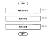
- FIG. 5 is a flowchart illustrating an operation example of the imaging apparatus 100 according to an embodiment of the present disclosure.
- FIG. 5 shows the composition designation process in step S101 of FIG. 4 in more detail.
- the composition specifying unit 114 causes the user to specify the feature points of the subject to be processed (step S111).
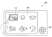
- FIG. 6 is an explanatory diagram illustrating an example of a screen displayed on the display unit 120 when the feature point of the target subject is designated by the user in step S111.
- FIG. 6 shows a Shinkansen vehicle body, a human face, a cat face, a moon, a bird face, and an airplane body as clockwise examples from the upper left as subject feature points to be designated by the user.
- the feature points of the subject specified by the user are not limited to those.
- the imaging apparatus 100 may prepare an example of feature points of a subject in advance and allow the user to select a feature point, or may cause a user to specify a feature point of an arbitrary object.
- FIG. 6 shows a state where the user has selected a Shinkansen vehicle body as a subject, and the Shinkansen vehicle body is surrounded by a frame line 171.
- the touch panel 122 is provided in the imaging apparatus 100, the feature point of the subject is designated by causing the user to touch the display unit 120 with a finger as shown in FIG.
- the present disclosure is not limited to the example in which the feature point of the target subject is designated, and the feature point of the subject may be designated by causing the user to operate the operation unit 130.
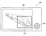
- FIG. 7 is an explanatory diagram illustrating an example of a screen displayed on the display unit 120 when the user designates a composition in step S112.
- an example of a screen displayed on the display unit 120 when the user selects the Shinkansen vehicle body as a subject feature point and designates the position of the Shinkansen vehicle body is shown.
- the composition is designated by causing the user to touch the display unit 120 with a finger.
- FIG. 7 shows a frame line 172 for designating the composition.
- the present disclosure is not limited to the example in which the composition is designated, and the composition may be designated by causing the user to operate the operation unit 130.
- the composition designating unit 114 When the user designates an arbitrary composition in this way, for example, the composition designating unit 114 then stores the designated composition in the flash memory 140 (step S102).
- step S102 the imaging apparatus 100 continues to detect whether the feature point designated by the user is included in the image captured by the imaging unit 102 or not. Is executed (step S103). This feature point detection process is executed by, for example, the composition detection unit 111.
- the imaging apparatus 100 determines whether the feature point designated by the user is included in the image captured by the imaging unit 102 (step S104). For example, the composition detection unit 111 executes the determination process in step S104.
- step S104 if the feature point designated by the user is not included in the image captured by the imaging unit 102, the process returns to step S103, and the imaging device 100 executes the feature point detection process again. To do.
- step S104 if the feature point designated by the user is included in the image captured by the image capturing unit 102, the image capturing apparatus 100 subsequently moves the detected feature point in the moving direction. Then, the moving speed is obtained (step S105). For example, the composition detection unit 111 executes the process of obtaining the moving direction and moving speed of the detected feature point in step S105.
- FIG. 8 is an explanatory diagram for explaining the process of obtaining the moving direction and moving speed of the detected feature point in step S105.
- the composition detection unit 111 can obtain the moving direction of the feature point by detecting that the feature point is moving from the upper left to the lower right of the image. If it can be detected that the detected feature point is moving linearly as shown in FIG. 8, the composition detection unit 111 can obtain the moving speed of the feature point.
- step S105 When the moving direction and moving speed of the detected feature point are obtained in step S105, the imaging apparatus 100 subsequently moves to the position designated by the user when the detected feature point is moving linearly.
- the time for the detected feature point to reach is calculated (step S106).
- the composition detection unit 111 executes the time calculation processing in step S106.
- FIG. 9 is an explanatory diagram for explaining the time calculation process in step S106.
- the feature point is located at the position designated by the user at time T1 after 900 milliseconds, for example, from the moving speed of the feature point.
- the composition detection unit 111 can calculate that it has reached.
- the imaging apparatus 100 calculates the time lag from when the imaging start trigger is issued until the imaging operation starts.
- the release correction time is determined (step S107).
- the release correction time is a time corresponding to the difference between the time when the feature point reaches the position designated by the user and the time when the trigger for actually starting imaging is issued.
- the time lag calculation process in step S107 is executed by the time lag calculation unit 112, for example.
- examples of factors that cause a time lag include, for example, the inherent processing speed of the imaging apparatus 100, the driving speed of the shutter curtain and the aperture of the imaging apparatus 100, the driving speed of the shutter curtain and the aperture specific to the lens, and the imaging apparatus.
- There are a processing speed that dynamically changes depending on the control state of 100 a processing speed that dynamically changes depending on the control state of the lens, and the like.
- the time lag from the state of the imaging device 100 or the lens depends on the processing performance of the imaging device 100.
- step S107 the time lag calculation unit 112 starts from when the composition detection unit 111 issues the trigger to the imaging control unit 113 until the imaging control unit 113 starts imaging processing. Time is calculated and the calculated time is notified to the composition detection unit 111.
- FIG. 10 is an explanatory diagram for explaining the time lag calculation processing in step S107.
- the time lag calculation unit 112 calculates that the time lag from when the imaging start trigger is issued to when the imaging operation is started is 20 milliseconds as a result of the time lag calculation process in step S107
- the time lag calculation unit 112 detects composition of the time lag information. Notification to the unit 111.
- the time lag calculation unit 112 may obtain the time lag by calculation when the feature point of the subject is detected. However, when the processing performance of the imaging device 100 is not high, the time lag calculation unit 112 is based on the setting state of the imaging device 100. Alternatively, a fixed value held in advance may be referred to.
- the imaging apparatus 100 determines whether the release timing has been reached from the time calculated in step S106 and the release correction time determined in step S107 ( Step S108).
- the determination of whether or not the release timing has been reached in step S108 is executed by, for example, the composition detection unit 111.
- a time lag release correction time
- the imaging apparatus 100 issues an imaging start trigger 20 milliseconds before the time T1 calculated in step S106, the imaging apparatus 100 captures an image in which a feature point exists at the position specified by the user. can do.
- step S108 if it is determined that the release timing has not been reached, the imaging apparatus 100 executes the feature point detection process in step S103 again. On the other hand, if it is determined that the release timing has been reached as a result of the determination in step S108, the imaging apparatus 100 performs release by issuing a trigger for starting imaging (step S109).
- the composition detection unit 111 issues a trigger for starting imaging to the imaging control unit 113.
- the imaging apparatus 100 performs the automatic imaging process in consideration of the time lag from when the imaging start trigger is issued until the imaging operation is started. As described above, by performing the automatic imaging process in consideration of the time lag, the imaging apparatus 100 according to an embodiment of the present disclosure executes imaging of the image with the composition specified by the user as the user intends. can do.
- the image capturing apparatus 100 may display the image captured by the release on the display unit 120 after executing the release in step S109, and correct the release correction time and the release timing when displaying the image. If not, the position of the subject may be superimposed on the image. In the above example, the imaging apparatus 100 may display the release correction time such as “20 msec” and superimpose it on the image. In addition, the imaging apparatus 100 may represent the position of the subject when correction is not performed by shifting the subject itself by image processing, or may be represented by an arbitrary mark or the like instead of the subject itself.
- the release correction time and the position of the subject when the release timing is not corrected are displayed superimposed on the image, so that the skill of the user of the imaging apparatus 100 regarding the release timing can be expected to improve.
- the imaging apparatus 100 starts the imaging operation after the time T1 when the feature point reaches the position specified by the user and the imaging start trigger are issued.
- the time lag to do was calculated.
- the subject to be imaged by the user using the imaging device 100 does not necessarily move linearly in the image, and may move in a curved manner in the image.
- the time lag is calculated as described above, and even if the imaging device 100 determines that the release timing has come, the user actually The subject may not exist at the specified position.
- the imaging apparatus 100 may allow position designation in a wider range, rather than position designation at one point on the screen, that is, so-called pinpoint position designation, when the user designates the composition. Further, in addition to pinpoint position designation, the imaging apparatus 100 designates a range in which the subject is assumed to move linearly, and when the subject is within the range, the user designates as described above. The time T1 at which the feature point arrives at the position and the time lag from when the imaging start trigger is issued until the imaging operation is started may be calculated.
- FIG. 11 is an explanatory diagram for explaining a case where the user of the imaging apparatus 100 is allowed to specify a wider range rather than pinpointing a position.
- a reference numeral 173 in FIG. 11 is a frame line indicating a range designated by the user.
- the composition specifying unit 114 may allow the user to specify a wider range than when the position is specified by pinpoint.
- the imaging apparatus 100 may automatically determine whether the position is specified in a pinpoint or in a wider range from the movement of the feature points. For example, if the feature point moves linearly within a certain time range, the imaging apparatus 100 may execute an automatic imaging process based on pinpoint position designation.
- the imaging apparatus 100 has performed the automatic imaging process of still images taking into account the time lag from when the trigger for starting imaging is issued until the imaging operation is started. It is not limited to examples.
- the imaging apparatus 100 may start the moving image imaging operation when the subject reaches the vicinity of the location specified by the user, and may end the moving image imaging operation when the subject moves away from the vicinity of the location specified by the user. . Then, the imaging apparatus 100 may extract a frame in which a subject is present at a location designated by the user from the moving images thus captured and record the frame as a still image.
- the imaging apparatus 100 that performs the automatic imaging process of a still image taking into account the time lag from when the trigger for starting imaging is issued until the imaging operation is started. Can be provided. By executing the still image automatic imaging process taking into account the time lag, the imaging apparatus 100 captures a still image with a composition reflecting the user's intention even when the subject moves at high speed. Can do.
- each step in the processing executed by each device in this specification does not necessarily have to be processed in chronological order in the order described as a sequence diagram or flowchart.
- each step in the processing executed by each device may be processed in an order different from the order described as the flowchart, or may be processed in parallel.
- a digital still camera has been described as an example.
- an apparatus to which the present disclosure is applied is not limited to such an example.
- the technology according to the present disclosure can also be provided in a mobile phone, a game machine, a personal computer, a tablet terminal, and other information processing apparatuses equipped with a camera.
- this technique can also take the following structures.
- a composition detection unit that calculates a time when the subject specified by the user included in the captured image becomes the composition specified by the user;
- a time calculation unit for calculating a time from when an instruction to start an imaging operation is performed until an image is captured;
- An imaging control unit that starts an imaging process of an image in response to an instruction to start an imaging operation;
- the composition detection unit instructs the imaging control unit to start an imaging operation before a time calculated by the time calculation unit from a time when the composition specified by the user is reached.
- the imaging control unit superimposes the time information calculated by the time calculation unit on an image obtained by an imaging operation performed based on an instruction from the composition detection unit.
- the imaging control unit converts information on the position of the subject when the imaging operation is executed at the time calculated by the composition detection unit into an image obtained by the imaging operation executed based on an instruction from the composition detection unit.
- the composition detection unit according to any one of (1) to (5), wherein the composition detection unit instructs the imaging control unit to start an imaging operation only when the subject is continuously included in the captured image. Imaging device.
- composition detection unit changes a timing for starting calculation of a time at which the composition specified by the user starts according to a method for specifying the composition by the user. apparatus.
- a method of specifying a composition by the user is changed depending on whether the subject moves linearly or curvedly.
- the composition detection step is a computer program for instructing to start an imaging operation in the imaging control step when the composition calculation step is before the time calculated in the time calculation step from the time specified by the user.
Landscapes
- Engineering & Computer Science (AREA)
- Multimedia (AREA)
- Signal Processing (AREA)
- Physics & Mathematics (AREA)
- General Physics & Mathematics (AREA)
- Human Computer Interaction (AREA)
- Studio Devices (AREA)
Abstract
【課題】構図の検出から撮像動作の開始までのタイムラグを考慮に入れた構図検出及び自動撮像処理を実行することが可能な撮像装置を提供する。 【解決手段】撮像されている画像に含まれているユーザが指定した被写体が、該ユーザが指定した構図になる時刻を算出する構図検出部と、撮像動作の開始指示がされてから画像が撮像されるまでの時間を算出する時間算出部と、撮像動作の開始指示を受けて画像の撮像処理を開始する撮像制御部と、を備え、前記構図検出部は、前記ユーザが指定した構図になる時間から、前記時間算出部が算出した時間の前になると前記撮像制御部に撮像動作の開始を指示する、撮像装置が提供される。
Description
本開示は、撮像装置、撮像装置の制御方法及びコンピュータプログラムに関する。
フィルムや感光板を使って撮影する銀塩カメラに代わって、CCD(Charge Coupled Device)やCMOS(ComplementaryMetal Oxide Semiconductor)などの固体撮像素子からなるイメージ・センサで捕捉した画像をデジタル符号化するデジタルカメラが広範に普及している。デジタルカメラによれば、デジタル符号化された画像をメモリに記憶し、コンピュータによる画像処理や画像管理を行なうことができ、さらにフィルムの寿命という問題がないといった利点がある。
写真を電子的に撮像するデジタルカメラを使用することで、操作に不慣れなユーザであっても手軽に鮮明な写真を撮ることが出来る。しかし、どのタイミングでシャッタレリーズボタンを押せば構図の良い写真を撮ることが出来るかというスキルを、初心者がいきなり身に付けるのは難しい。
そこで、デジタルカメラの扱いに慣れていない初心者でも、構図の良い写真を簡単に撮影することが出来るための技術が考えられており、またそのような技術を開示する文献も公開されている。
例えば特許文献1は、デジタルカメラが構図を検出して自動的に撮像処理を実行し、またユーザが指定した構図を検出するとユーザに通知する技術を開示している。また特許文献2は、シャッタレリーズボタンが押下されてから撮像素子への露光動作が開始されるまでのタイムラグによる撮影の失敗を防ぐために、光学ファインダから入力された画像をデジタルカメラの画面に表示する技術を開示している。
しかし、構図を検出して自動撮像を実行する場合、通常のデジタルカメラは、構図の検出から撮像動作の開始までのタイムラグが存在し、撮像したい構図と実際に撮像される画像との間にずれが生じる。特に高速で移動する被写体を撮像しようとする場合にこの現象が顕著となる。また特許文献2で開示された技術を用いても、シャッタレリーズボタンの操作のタイミングは結局ユーザに依存することになるので、構図の検出から撮像動作の開始までのタイムラグは解決されない。
そこで本開示は、構図の検出から撮像動作の開始までのタイムラグを考慮に入れた構図検出及び自動撮像処理を実行することが可能な、新規かつ改良された撮像装置、撮像装置の制御方法及びコンピュータプログラムを提供する。
本開示によれば、撮像されている画像に含まれているユーザが指定した被写体が、該ユーザが指定した構図になる時刻を算出する構図検出部と、撮像動作の開始指示がされてから画像が撮像されるまでの時間を算出する時間算出部と、撮像動作の開始指示を受けて画像の撮像処理を開始する撮像制御部と、を備え、前記構図検出部は、前記ユーザが指定した構図になる時間から、前記時間算出部が算出した時間の前になると前記撮像制御部に撮像動作の開始指示を行なう、撮像装置が提供される。
また本開示によれば、撮像されている画像に含まれているユーザが指定した被写体が、前記ユーザが指定した構図になる時刻を算出することと、撮像動作の開始指示がされてから画像が撮像されるまでの時間を算出することと、撮像動作の開始指示を受けて画像の撮像処理を開始することと、を含み、前記ユーザが指定した構図になる時間から、前記算出された時間の前になると前記撮像動作の開始指示を行なう、撮像装置の制御方法が提供される。
また本開示によれば、コンピュータに、撮像されている画像に含まれているユーザが指定した被写体が、前記ユーザが指定した構図になる時刻を算出することと、撮像動作の開始指示がされてから画像が撮像されるまでの時間を算出することと、撮像動作の開始指示を受けて画像の撮像処理を開始することと、を実行させ、前記ユーザが指定した構図になる時間から、前記算出された時間の前になると前記撮像動作の開始指示を行なう、コンピュータプログラムが提供される。
以上説明したように本開示によれば、構図の検出から撮像動作の開始までのタイムラグを考慮に入れた構図検出及び自動撮像処理を実行することが可能な、新規かつ改良された撮像装置、撮像装置の制御方法及びコンピュータプログラムを提供することができる。
以下に添付図面を参照しながら、本開示の好適な実施の形態について詳細に説明する。なお、本明細書及び図面において、実質的に同一の機能構成を有する構成要素については、同一の符号を付することにより重複説明を省略する。
なお、説明は以下の順序で行うものとする。
<1.本開示の一実施形態>
[撮像装置の外観例]
[撮像装置の機能構成例]
[撮像装置の動作例]
<2.まとめ>
<1.本開示の一実施形態>
[撮像装置の外観例]
[撮像装置の機能構成例]
[撮像装置の動作例]
<2.まとめ>
<1.本開示の一実施形態>
[撮像装置の外観例]
まず、図面を参照しながら、本開示の情報処理装置の一例として、本開示の一実施形態にかかる撮像装置の外観例について説明する。図1は、本開示の一実施形態に係る撮像装置100の外観例を、撮像装置100の背面側から斜視図で示す説明図である。以下、図1を用いて本開示の一実施形態に係る撮像装置100の外観例について説明する。
[撮像装置の外観例]
まず、図面を参照しながら、本開示の情報処理装置の一例として、本開示の一実施形態にかかる撮像装置の外観例について説明する。図1は、本開示の一実施形態に係る撮像装置100の外観例を、撮像装置100の背面側から斜視図で示す説明図である。以下、図1を用いて本開示の一実施形態に係る撮像装置100の外観例について説明する。
図1に示したように本開示の一実施形態に係る撮像装置100は、筐体101に、表示部120と、操作部130と、が設けられる。
表示部120は、撮像装置100が撮像した画像を表示したり、撮像装置100の各種設定画面を表示したりする。後述するが、表示部120にはタッチパネルが設けられており、撮像装置100のユーザは、表示部120に設けられるタッチパネルを指等の操作部材で触ることで、撮像装置100を操作することが出来る。
操作部130は、ユーザに撮像装置100を操作させるためのものであり、撮像装置100を操作するためのボタンやスイッチ等で構成される。図1には、操作部130として、ズームボタン131と、シャッタボタン132と、電源ボタン133と、が図示されている。ズームボタン131は、撮像装置100での撮像時の倍率を変化させるためのボタンである。シャッタボタン132は、撮像装置100で画像を撮像するためのボタンである。そして電源ボタン133は、撮像装置100の電源をオン・オフするためのボタンである。
撮像装置100の外観は係る例に限定されるものではないことは言うまでもない。また、操作部130を構成するボタンやスイッチも、図1に示したものに限定されるものではないことは言うまでもない。
本開示の一実施形態に係る撮像装置100は、ユーザが指定した被写体が、ユーザが指定した位置に達すると、自動的に撮像動作を開始する。そして本開示の一実施形態に係る撮像装置100が、その自動的な撮像動作の際に、構図の検出から撮像動作の開始までのタイムラグを考慮に入れる。構図の検出から撮像動作の開始までのタイムラグを考慮に入れることで、本開示の一実施形態に係る撮像装置100は、ユーザが意図した構図での撮像を実現できる。
なお、図1に示した本開示の一実施形態に係る撮像装置100の外観は一例にすぎないものであり、撮像装置100の外観は図1に示したようなものだけでなく様々な形態を採り得ることは言うまでもない。
以上、図1を用いて本開示の一実施形態に係る撮像装置100の外観例について説明した。次に、本開示の一実施形態に係る撮像装置100の機能構成例について説明する。
[撮像装置の機能構成例]
図2は、本開示の一実施形態に係る撮像装置100の機能構成例を示す説明図である。以下、図2を用いて本開示の一実施形態に係る撮像装置100の機能構成例について説明する。
図2は、本開示の一実施形態に係る撮像装置100の機能構成例を示す説明図である。以下、図2を用いて本開示の一実施形態に係る撮像装置100の機能構成例について説明する。
図2に示したように、本開示の一実施形態に係る撮像装置100は、撮像部102と、制御部110と、表示部120と、操作部130と、フラッシュメモリ140と、RAM150と、を含んで構成される。
撮像部102は、レンズ、CCD(Charge Coupled Device)やCMOS(ComplementaryMetal Oxide Semiconductor)などの固体撮像素子からなるイメージャ、イメージ・センサへの露光タイミング等を制御するタイミングジェネレータ、サンプルホールド回路、イメージャへの露光により得られる画像の元データを後段の回路に提供するためのインタフェース部などで構成される。なお、本実施形態では、撮像装置100に撮像部102が設けられている構成を示したが、本開示は係る例に限定されるものではなく、撮像装置100からレンズが着脱可能な構成であっても良い。
制御部110は、撮像装置100の動作を制御する。制御部110は、例えば、フラッシュメモリ140に記録されているコンピュータプログラムを読み出して、コンピュータプログラムを順次実行することで、撮像装置100の動作を制御してもよい。制御部110の具体的構成例については、後に詳述する。
表示部120は、上述したように、撮像装置100が撮像部102で撮像した画像を表示したり、撮像装置100の各種設定画面を表示したりする。図2に示したように、表示部120は、表示パネル121と、タッチパネル122と、を含んで構成される。表示パネル121は、撮像装置100が撮像した画像を表示したり、撮像装置100の各種設定画面を表示したりするものであり、例えば液晶表示パネルや有機EL表示パネル等の平板表示パネルから成るものである。タッチパネル122は、表示パネル121の表示面に設けられる。ユーザは、タッチパネル122を指等の操作部材で触ることで、撮像装置100の操作を可能にする。従って、制御部110は、タッチパネル122への操作部材の接触状態に応じて各種処理を実行する。
操作部130は、上述したように、ユーザに撮像装置100を操作させるためのものであり、撮像装置100を操作するためのボタンやスイッチ等で構成される。制御部110は、操作部130の操作状態に応じて各種処理を実行する。操作部130の操作状態に応じて制御部110が実行する各種処理は、例えば撮像装置100の電源オン・オフの処理、撮像の際の倍率の変更処理その他の撮像条件の変更処理、静止画像又は動画像の撮像処理等である。
フラッシュメモリ140は、制御部110の処理に必要な各種コンピュータプログラムや、各種データが記憶される不揮発性メモリである。またRAM150は、制御部110の処理の際に用いられるワーキングメモリである。
なお、制御部110と、表示部120と、操作部130と、フラッシュメモリ140と、RAM150とは、バス160を介して相互に接続されており、相互に通信することが可能である。
以上、図2を用いて本開示の一実施形態に係る撮像装置100の機能構成例について説明した。次に、本開示の一実施形態に係る撮像装置100に含まれる、制御部110の機能構成例について説明する。
図3は、本開示の一実施形態に係る撮像装置100に含まれる制御部110の機能構成例を示す説明図である。以下、図3を用いて本開示の一実施形態に係る撮像装置100に含まれる制御部110の機能構成例について説明する。
図3に示したように、本開示の一実施形態に係る制御部110は、構図検出部111と、タイムラグ算出部112と、撮像制御部113と、構図指定部114と、を含んで構成される。
構図検出部111は、撮像部102によって撮像されている画像が、ユーザの意図した構図となっているかどうかを検出する。本実施形態では、構図検出部111は、ユーザが指定した被写体の特徴点が、ユーザが指定した表示部120上の場所にあるかどうかによって、撮像部102によって撮像されている画像が、ユーザの意図した構図となっているかどうかを検出する。また構図検出部111は、ユーザが指定した被写体の特徴点が、撮像部102によって撮像されている画像中に存在している場合に、ユーザが指定した表示部120上の場所にその特徴点が達するまでの時間を算出する。
構図検出部111は、ユーザが指定した被写体の特徴点が、ユーザが指定した表示部120上の場所に存在することを検出すると、後述の撮像制御部113に対して、自動的に撮像動作を開始するためのトリガを発行する。
しかし、構図検出部111が撮像制御部113に対して上記トリガを発行してから、撮像制御部113が撮像処理を開始するまでには、撮像装置100のハードウェア的な要因やソフトウェア的な要因、また、撮像時の環境に起因するタイムラグが存在する。そのため、ユーザが指定した被写体の特徴点が、ユーザが指定した表示部120上の場所に存在した時点で構図検出部111が撮像制御部113に対して上記トリガをすると、その被写体が移動するような場合に、ユーザの意図した構図の画像を得ることが出来ない。
そこで本実施形態では、後述のタイムラグ算出部112により、構図検出部111が撮像制御部113に対して上記トリガを発行してから、撮像制御部113が撮像処理を開始するまでの時間を算出する。そして構図検出部111は、タイムラグ算出部112が算出した時間を考慮に入れて、撮像制御部113に対して、自動的に撮像動作を開始するためのトリガを発行する。
本実施形態に係る撮像装置100は、このように、構図検出部111が撮像制御部113に対して上記トリガを発行してから、撮像制御部113が撮像処理を開始するまでの時間を考慮に入れることで、ユーザが意図した通りの構図の画像を得ることが出来るようになる。
タイムラグ算出部112は、上述したように、構図検出部111が撮像制御部113に対して上記トリガを発行してから、撮像制御部113が撮像処理を開始するまでの時間(タイムラグ)を算出する。このタイムラグは、上述したように、撮像装置100のハードウェア的な要因やソフトウェア的な要因、また撮像時の環境に起因する。
このタイムラグをもたらす要因の例としては、例えば、撮像装置100の固有の処理速度、撮像装置100のシャッタ幕や絞りの駆動速度、レンズ固有のシャッタ幕や絞りの駆動速度、撮像装置100の制御状態により動的に変化する処理速度、レンズの制御状態により動的に変化する処理速度等がある。タイムラグ算出部112は、これらのタイムラグをもたらす要因に起因する、構図検出部111が撮像制御部113に対して上記トリガを発行してから撮像制御部113が撮像処理を開始するまでの時間(タイムラグ)を算出し、算出した時間を構図検出部111に通知する。構図検出部111は、タイムラグ算出部112が算出した時間を考慮して、撮像制御部113に対して上記トリガを発行する。
撮像制御部113は、ユーザによるシャッタボタン132の押下や、構図検出部111からの撮像動作を開始するためのトリガの受信に応じて撮像処理を実行する。撮像制御部113は、ユーザによるシャッタボタン132の押下や、構図検出部111からの撮像動作を開始するためのトリガの受信に応じ、撮像部102に対して撮像画像の取得を指示する。撮像制御部113の指示により取得された撮像画像は、フラッシュメモリ140に保存されたり、表示部120に表示されたりする。
構図指定部114は、ユーザに対して任意の構図を指定させる。構図指定部114がユーザに指定させた構図に関する情報はフラッシュメモリ140に記憶される。構図指定部114は、ユーザに構図を指定させる際に、対象となる被写体(またはその被写体の特徴点)と、その被写体が写っていて欲しい画像中の位置とを指定させる。
以上、図3を用いて本開示の一実施形態に係る制御部110の機能構成例について説明した。次に、本開示の一実施形態に係る撮像装置100の動作例について説明する。
[撮像装置の動作例]
図4は、本開示の一実施形態に係る撮像装置100の動作例を示す流れ図である。図4に示したのは、撮像部102で撮像している画像の内容を制御部110で検出して、自動的に撮像動作を実行する際の、撮像装置100の動作例を示したものである。以下、図4を用いて本開示の一実施形態に係る撮像装置100の動作例について説明する。
図4は、本開示の一実施形態に係る撮像装置100の動作例を示す流れ図である。図4に示したのは、撮像部102で撮像している画像の内容を制御部110で検出して、自動的に撮像動作を実行する際の、撮像装置100の動作例を示したものである。以下、図4を用いて本開示の一実施形態に係る撮像装置100の動作例について説明する。
まず撮像装置100は、ユーザに対して任意の構図を指定させる(ステップS101)。このステップS101の構図の指定は、例えば構図指定部114が実行する。撮像装置100は、ステップS101で、ユーザに対して任意の構図を指定させると、続いて指定させた構図を記憶する(ステップS102)。このステップS102は、例えば構図指定部114がユーザに指定させた構図に関する情報をフラッシュメモリ140に記憶させることで実行される。
図5は、本開示の一実施形態に係る撮像装置100の動作例を示す流れ図である。図5に示したのは、図4のステップS101の構図の指定処理をより詳細に示したものである。
例えば構図指定部114は、ユーザに対して対象となる被写体の特徴点を指定させる(ステップS111)。図6は、ステップS111でユーザに対して対象となる被写体の特徴点を指定させる際に、表示部120に表示される画面の例を示す説明図である。図6には、ユーザに指定させる被写体の特徴点の例として、左上から時計回りに、新幹線の車体、人間の顔、猫の顔、月、鳥の顔、飛行機の機体が示されている。
もちろんユーザに指定させる被写体の特徴点は係るものに限定されるものではない。例えば、撮像装置100が予め被写体の特徴点の例を用意してユーザに選択させるようにしてもよく、任意の物体の特徴点をユーザに指定させるようにしてもよい。図6には、ユーザが被写体として新幹線の車体を選択した状態が示されており、新幹線の車体は枠線171で囲まれている。
本実施形態では、撮像装置100にタッチパネル122が設けられているので、図6に示したように、ユーザに表示部120を指で触らせることで、被写体の特徴点を指定させている。もちろん本開示は、対象となる被写体の特徴点を指定させる方法は係る例に限定されるものではなく、ユーザに操作部130を操作させることで被写体の特徴点を指定させてもよい。
ユーザに対して対象となる被写体の特徴点を指定させると、続いて、例えば構図指定部114は、ユーザに対して、指定された特徴点の位置を指定させることで構図を指定させる(ステップS112)。図7は、ステップS112でユーザに構図を指定させる際に、表示部120に表示される画面の例を示す説明図である。ここでは、ユーザが被写体の特徴点として新幹線の車体を選択した場合に、その新幹線の車体の位置を指定するときの、表示部120に表示される画面の例が示されている。
本実施形態では、撮像装置100にタッチパネル122が設けられているので、図7に示したように、ユーザに表示部120を指で触らせることで、構図を指定させている。図7には、構図を指定させるための枠線172が示されている。もちろん本開示は、構図を指定させる方法は係る例に限定されるものではなく、ユーザに操作部130を操作させることで構図を指定させてもよい。
このようにユーザに対して任意の構図を指定させると、続いて、例えば構図指定部114は、指定させた構図をフラッシュメモリ140へ記憶する(ステップS102)。
図4に戻って本開示の一実施形態に係る撮像装置100の動作例の続きを説明する。ステップS102で、ユーザに指定させた構図を記憶すると、続いて撮像装置100は、ユーザに指定させた特徴点が、撮像部102で撮像している画像に含まれているかどうかの特徴点検出処理を実行する(ステップS103)。この特徴点検出処理は、例えば構図検出部111が実行する。
上記ステップS103で特徴点検出処理を実行すると、続いて撮像装置100は、撮像部102で撮像している画像に、ユーザに指定させた特徴点が含まれているかを判断する(ステップS104)。このステップS104の判断処理は、例えば構図検出部111が実行する。
ステップS104の判断の結果、撮像部102で撮像している画像に、ユーザに指定させた特徴点が含まれていなければ、上記ステップS103に戻って、撮像装置100は特徴点検出処理を再度実行する。一方、ステップS104の判断の結果、撮像部102で撮像している画像に、ユーザに指定させた特徴点が含まれていれば、続いて撮像装置100は、その検出された特徴点の移動方向及び移動速度を求める(ステップS105)。ステップS105の、検出された特徴点の移動方向及び移動速度を求める処理は、例えば構図検出部111が実行する。
図8は、上記ステップS105の、検出された特徴点の移動方向及び移動速度を求める処理を説明するための説明図である。例えば図8のように、特徴点が画像の左上から右下方向に移動していることを検出することで、構図検出部111は、特徴点の移動方向を求めることができる。また検出された特徴点が図8のように直線的に移動していることを検出できると、構図検出部111はその特徴点の移動速度を求めることができる。
上記ステップS105で、検出された特徴点の移動方向及び移動速度を求めると、続いて撮像装置100は、その検出された特徴点が直線的に移動している場合に、ユーザが指定した位置にその検出された特徴点が到達する時間を算出する(ステップS106)。ステップS106の時間の算出処理は、例えば構図検出部111が実行する。
図9は、上記ステップS106の、時間の算出処理を説明するための説明図である。例えば、検出された特徴点が画像の左上から右下方向に移動している場合に、その特徴点の移動速度から、例えば900ミリ秒後の時間T1にユーザが指定した位置にその特徴点が到達する、と構図検出部111は算出することができる。
上記ステップS106で、ユーザが指定した位置に特徴点が到達する時間を算出すると、続いて撮像装置100は、撮像開始のトリガが発行されてから撮像動作を開始するまでのタイムラグを算出することで、レリーズ補正時間を決定する(ステップS107)。レリーズ補正時間とは、ユーザが指定した位置に特徴点が到達する時刻と、実際に撮像開始のトリガを発行する時刻との差に相当する時間である。このステップS107のタイムラグの算出処理は、例えばタイムラグ算出部112が実行する。
上述したように、タイムラグをもたらす要因の例としては、例えば、撮像装置100の固有の処理速度、撮像装置100のシャッタ幕や絞りの駆動速度、レンズ固有のシャッタ幕や絞りの駆動速度、撮像装置100の制御状態により動的に変化する処理速度、レンズの制御状態により動的に変化する処理速度等がある。また、撮像装置100やレンズの状態からのタイムラグは、撮像装置100の処理性能によって左右される。
タイムラグ算出部112は、上記ステップS107において、これらの要因に起因する、構図検出部111が撮像制御部113に対して上記トリガを発行してから、撮像制御部113が撮像処理を開始するまでの時間を算出し、算出した時間を構図検出部111に通知する。
図10は、上記ステップS107の、タイムラグの算出処理を説明するための説明図である。例えばタイムラグ算出部112は、ステップS107のタイムラグ算出処理の結果、撮像開始のトリガが発行されてから撮像動作を開始するまでのタイムラグが20ミリ秒であると算出すると、そのタイムラグの情報を構図検出部111に通知する。
なお、タイムラグ算出部112は、被写体の特徴点が検出されている際に計算によってタイムラグを求めても良いが、撮像装置100の処理性能が高くない場合には、撮像装置100の設定状態に基づき、予め保持しておいた固定値を参照するようにしてもよい。
上記ステップS107でレリーズ補正時間を決定すると、続いて撮像装置100は、上記ステップS106で算出した時間と、上記ステップS107で決定したレリーズ補正時間とから、レリーズタイミングに到達したかどうかを判定する(ステップS108)。このステップS108のレリーズタイミングに到達したかどうかの判定は、例えば構図検出部111が実行する。
例えば、上記ステップS106でユーザが指定した位置に特徴点が到達する時間T1を算出し、上記ステップS107で撮像開始のトリガが発行されてから撮像動作を開始するまでのタイムラグ(レリーズ補正時間)が20ミリ秒であると算出すると、撮像装置100は、上記ステップS106で算出した時間T1の20ミリ秒前に撮像開始のトリガを発行すると、ユーザが指定した位置に特徴点が存在する画像を撮像することができる。
上記ステップS108の判断の結果、レリーズタイミングに到達していないと判断すると、撮像装置100は、上記ステップS103の特徴点検出処理を再度実行する。一方、上記ステップS108の判断の結果、レリーズタイミングに到達したと判断すると、撮像装置100は、撮像開始のトリガを発行することでレリーズを行なう(ステップS109)。撮像開始のトリガは、構図検出部111が撮像制御部113に対して発行する。
このように、本開示の一実施形態に係る撮像装置100は、撮像開始のトリガが発行されてから撮像動作を開始するまでのタイムラグを考慮に入れた自動撮像処理を実行する。このように、タイムラグを考慮に入れて自動撮像処理を実行することで、本開示の一実施形態に係る撮像装置100は、ユーザが指定した構図での画像の撮像を、ユーザの意図通りに実行することができる。
なお撮像装置100は、上記ステップS109によりレリーズを実行した後に、そのレリーズによって撮像した画像を表示部120に表示してもよく、その画像の表示の際に、レリーズ補正時間や、レリーズタイミングを補正しなかった場合の被写体の位置をその画像に重畳してもよい。上述の例では、撮像装置100は、「20msec」等のようにレリーズ補正時間を表記して、画像に重畳してもよい。また撮像装置100は、補正しなかった場合の被写体の位置を、被写体そのものを画像処理によってずらすことで表現してもよく、被写体そのものではなく任意のマーク等で表現してもよい。
このように、レリーズ補正時間や、レリーズタイミングを補正しなかった場合の被写体の位置をその画像に重畳して提示することで、レリーズタイミングについての撮像装置100のユーザのスキル向上が期待できる。
上述の説明では、撮像装置100は、被写体が画像中を直線的に移動する場合に、ユーザが指定した位置に特徴点が到達する時間T1及び撮像開始のトリガが発行されてから撮像動作を開始するまでのタイムラグを算出していた。しかし、ユーザが撮像装置100を用いて撮像しようとする被写体は必ずしも画像中を直線的に移動するとは限らず、画像中を曲線的に移動する場合もあり得る。ユーザが撮像装置100を用いて撮像しようとする被写体が曲線的に移動する場合は、上述したようにタイムラグを算出し、レリーズタイミングになったと撮像装置100が判断しても、実際にはユーザが指定した位置にその被写体が存在しないことも考えられる。
そのため撮像装置100は、ユーザに構図を指定させる際に、画面上での一点での位置指定、いわゆるピンポイントでの位置指定ではなく、より広い範囲での位置指定を可能にしてもよい。また撮像装置100は、ピンポイントでの位置指定に加え、被写体が直線的に移動すると仮定する範囲を指定しておき、被写体がその範囲に入ったことを検出すると、上述のようにユーザが指定した位置に特徴点が到達する時間T1及び撮像開始のトリガが発行されてから撮像動作を開始するまでのタイムラグを算出するようにしてもよい。
図11は、撮像装置100のユーザに対して、ピンポイントでの位置指定ではなく、より広い範囲の指定を行わせる場合について説明するための説明図である。図11の符号173は、ユーザによって指定された範囲を示す枠線である。構図指定部114は、図11に示したように、ピンポイントで位置を指定させる場合に比べてより広い範囲をユーザに指定させるようにしてもよい。
また撮像装置100は、特徴点の動きから、ピンポイントでの位置指定か、より広い範囲での指定かを自動的に判断してもよい。例えば、ある時間の範囲で特徴点が直線的に移動していれば、撮像装置100は、ピンポイントでの位置指定による自動撮像処理を実行しても良い。
また上述の説明では、撮像装置100は、撮像開始のトリガが発行されてから撮像動作を開始するまでのタイムラグを考慮に入れた静止画像の自動撮像処理を実行していたが、本開示は係る例に限定されるものではない。
例えば撮像装置100は、ユーザが指定した場所の近傍に被写体が到達すると動画像の撮像動作を開始し、ユーザが指定した場所の近傍から離れると動画像の撮像動作を終了するようにしてもよい。そして撮像装置100は、そのようにして撮像した動画像の中から、ユーザが指定した場所に被写体が存在するフレームを抜き出して静止画像として記録するようにしてもよい。
<2.まとめ>
以上説明したように本開示の一実施形態によれば、撮像開始のトリガが発行されてから撮像動作を開始するまでのタイムラグを考慮に入れた静止画の自動撮像処理を実行する撮像装置100を提供することができる。タイムラグを考慮に入れた静止画の自動撮像処理を実行することで、被写体が高速で移動するような場合でも、撮像装置100は、ユーザの意図を反映させた構図での静止画を撮像することができる。
以上説明したように本開示の一実施形態によれば、撮像開始のトリガが発行されてから撮像動作を開始するまでのタイムラグを考慮に入れた静止画の自動撮像処理を実行する撮像装置100を提供することができる。タイムラグを考慮に入れた静止画の自動撮像処理を実行することで、被写体が高速で移動するような場合でも、撮像装置100は、ユーザの意図を反映させた構図での静止画を撮像することができる。
本明細書の各装置が実行する処理における各ステップは、必ずしもシーケンス図またはフローチャートとして記載された順序に沿って時系列に処理する必要はない。例えば、各装置が実行する処理における各ステップは、フローチャートとして記載した順序と異なる順序で処理されても、並列的に処理されてもよい。
また、各装置に内蔵されるCPU、ROMおよびRAMなどのハードウェアを、上述した各装置の構成と同等の機能を発揮させるためのコンピュータプログラムも作成可能である。また、該コンピュータプログラムを記憶させた記憶媒体も提供されることが可能である。また、機能ブロック図で示したそれぞれの機能ブロックをハードウェアで構成することで、一連の処理をハードウェアで実現することもできる。
上述した本開示の一実施形態ではデジタルスチルカメラを例示して説明したが、本開示が適用される装置は係る例に限定されるものではない。例えばカメラが搭載された携帯電話、ゲーム機、パーソナルコンピュータ、タブレット端末その他の情報処理装置においても、同様に本開示における技術を提供することが出来ることは言うまでもない。
以上、添付図面を参照しながら本開示の好適な実施形態について詳細に説明したが、本開示はかかる例に限定されない。本開示の属する技術の分野における通常の知識を有する者であれば、特許請求の範囲に記載された技術的思想の範疇内において、各種の変更例または修正例に想到し得ることは明らかであり、これらについても、当然に本開示の技術的範囲に属するものと了解される。
なお、本技術は以下のような構成も取ることができる。
(1)
撮像されている画像に含まれているユーザが指定した被写体が、該ユーザが指定した構図になる時刻を算出する構図検出部と、
撮像動作の開始指示がされてから画像が撮像されるまでの時間を算出する時間算出部と、
撮像動作の開始指示を受けて画像の撮像処理を開始する撮像制御部と、
を備え、
前記構図検出部は、前記ユーザが指定した構図になる時間から、前記時間算出部が算出した時間の前になると前記撮像制御部に撮像動作の開始指示を行なう、撮像装置。
(2)
前記時間算出部は、前記撮像装置の制御状態に応じて動的に変化する処理時間を考慮して前記時間を算出する、前記(1)に記載の撮像装置。
(3)
前記撮像制御部は、前記時間算出部が算出した前記時間の情報を、前記構図検出部からの指示に基づいて実行した撮像動作によって得られる画像に重畳させる、前記(1)または(2)に記載の撮像装置。
(4)
前記撮像制御部は、前記構図検出部が算出した前記時刻で撮像動作を実行した場合の前記被写体の位置の情報を、前記構図検出部からの指示に基づいて実行した撮像動作によって得られる画像に重畳させる、前記(1)~(3)のいずれかに記載の撮像装置。
(5)
前記撮像制御部は、前記被写体を切り抜いて前記被写体の位置の情報として用いる、前記(4)に記載の撮像装置。
(6)
前記構図検出部は、撮像されている画像に前記被写体が含まれ続けている場合に限り前記撮像制御部に撮像動作の開始を指示する、前記(1)~(5)のいずれかに記載の撮像装置。
(7)
前記構図検出部は、前記ユーザによる構図の指定方法に応じて前記ユーザが指定した構図になる時刻の算出を開始するタイミングを変化させる、前記(1)~(6)のいずれかに記載の撮像装置。
(8)
前記ユーザによる構図の指定方法は、前記被写体が直線的に移動するか曲線的に移動するかで変更される、前記(7)に記載の撮像装置。
(9)
撮像されている画像に含まれているユーザが指定した被写体が、前記ユーザが指定した構図になる時刻を算出する構図検出ステップと、
撮像動作の開始指示がされてから画像が撮像されるまでの時間を算出する時間算出ステップと、
撮像動作の開始指示を受けて画像の撮像処理を開始する撮像制御ステップと、
を備え、
前記構図検出ステップは、前記ユーザが指定した構図になる時間から、前記時間算出ステップで算出された時間の前になると前記撮像制御ステップで撮像動作の開始指示を行なう、撮像装置の制御方法。
(10)
コンピュータに、
撮像されている画像に含まれているユーザが指定した被写体が、前記ユーザが指定した構図になる時刻を算出する構図検出ステップと、
撮像動作の開始指示がされてから画像が撮像されるまでの時間を算出する時間算出ステップと、
撮像動作の開始指示を受けて画像の撮像処理を開始する撮像制御ステップと、
を備え、
前記構図検出ステップは、前記ユーザが指定した構図になる時間から、前記時間算出ステップで算出された時間の前になると前記撮像制御ステップで撮像動作の開始指示を行なう、コンピュータプログラム。
100 撮像装置
102 撮像部
110 制御部
111 構図検出部
112 タイムラグ算出部
113 撮像制御部
114 構図指定部
120 表示部
130 操作部
131 ズームボタン
132 シャッタボタン
133 電源ボタン
140 フラッシュメモリ
150 RAM
160 バス
102 撮像部
110 制御部
111 構図検出部
112 タイムラグ算出部
113 撮像制御部
114 構図指定部
120 表示部
130 操作部
131 ズームボタン
132 シャッタボタン
133 電源ボタン
140 フラッシュメモリ
150 RAM
160 バス
Claims (10)
- 撮像されている画像に含まれているユーザが指定した被写体が、該ユーザが指定した構図になる時刻を算出する構図検出部と、
撮像動作の開始指示がされてから画像が撮像されるまでの時間を算出する時間算出部と、
撮像動作の開始指示を受けて画像の撮像処理を開始する撮像制御部と、
を備え、
前記構図検出部は、前記ユーザが指定した構図になる時間から、前記時間算出部が算出した時間の前になると前記撮像制御部に撮像動作の開始指示を行なう、撮像装置。 - 前記時間算出部は、前記撮像装置の制御状態に応じて動的に変化する処理時間を考慮して前記時間を算出する、請求項1に記載の撮像装置。
- 前記撮像制御部は、前記時間算出部が算出した前記時間の情報を、前記構図検出部からの指示に基づいて実行した撮像動作によって得られる画像に重畳させる、請求項1に記載の撮像装置。
- 前記撮像制御部は、前記構図検出部が算出した前記時刻で撮像動作を実行した場合の前記被写体の位置の情報を、前記構図検出部からの指示に基づいて実行した撮像動作によって得られる画像に重畳させる、請求項1に記載の撮像装置。
- 前記撮像制御部は、前記被写体を切り抜いて前記被写体の位置の情報として用いる、請求項4に記載の撮像装置。
- 前記構図検出部は、撮像されている画像に前記被写体が含まれ続けている場合に限り前記撮像制御部に撮像動作の開始を指示する、請求項1に記載の撮像装置。
- 前記構図検出部は、前記ユーザによる構図の指定方法に応じて前記ユーザが指定した構図になる時刻の算出を開始するタイミングを変化させる、請求項1に記載の撮像装置。
- 前記ユーザによる構図の指定方法は、前記被写体が直線的に移動するか曲線的に移動するかで変更される、請求項7に記載の撮像装置。
- 撮像されている画像に含まれているユーザが指定した被写体が、前記ユーザが指定した構図になる時刻を算出することと、
撮像動作の開始指示がされてから画像が撮像されるまでの時間を算出することと、
撮像動作の開始指示を受けて画像の撮像処理を開始することと、
を含み、
前記ユーザが指定した構図になる時間から、前記算出された時間の前になると前記撮像動作の開始指示を行なう、撮像装置の制御方法。 - コンピュータに、
撮像されている画像に含まれているユーザが指定した被写体が、前記ユーザが指定した構図になる時刻を算出することと、
撮像動作の開始指示がされてから画像が撮像されるまでの時間を算出することと、
撮像動作の開始指示を受けて画像の撮像処理を開始することと、
を実行させ、
前記ユーザが指定した構図になる時間から、前記算出された時間の前になると前記撮像動作の開始指示を行なう、コンピュータプログラム。
Priority Applications (1)
| Application Number | Priority Date | Filing Date | Title |
|---|---|---|---|
| US14/763,091 US9554035B2 (en) | 2013-02-07 | 2014-01-22 | Image pickup device, method of controlling image pickup device, and computer program for automatically achieving composition specified by user |
Applications Claiming Priority (2)
| Application Number | Priority Date | Filing Date | Title |
|---|---|---|---|
| JP2013022247 | 2013-02-07 | ||
| JP2013-022247 | 2013-02-07 |
Publications (1)
| Publication Number | Publication Date |
|---|---|
| WO2014122990A1 true WO2014122990A1 (ja) | 2014-08-14 |
Family
ID=51299587
Family Applications (1)
| Application Number | Title | Priority Date | Filing Date |
|---|---|---|---|
| PCT/JP2014/051219 WO2014122990A1 (ja) | 2013-02-07 | 2014-01-22 | 撮像装置、撮像装置の制御方法及びコンピュータプログラム |
Country Status (2)
| Country | Link |
|---|---|
| US (1) | US9554035B2 (ja) |
| WO (1) | WO2014122990A1 (ja) |
Citations (2)
| Publication number | Priority date | Publication date | Assignee | Title |
|---|---|---|---|---|
| JP2002335436A (ja) * | 2001-05-08 | 2002-11-22 | Fuji Photo Film Co Ltd | カメラ |
| JP2005215373A (ja) * | 2004-01-30 | 2005-08-11 | Konica Minolta Photo Imaging Inc | 撮像装置 |
Family Cites Families (9)
| Publication number | Priority date | Publication date | Assignee | Title |
|---|---|---|---|---|
| JP3814363B2 (ja) * | 1997-02-18 | 2006-08-30 | キヤノン株式会社 | カメラ |
| US7027087B2 (en) * | 1998-08-21 | 2006-04-11 | Nikon Corporation | Electronic camera |
| JP2003222790A (ja) * | 2002-01-31 | 2003-08-08 | Minolta Co Ltd | カメラ |
| JP2005107213A (ja) * | 2003-09-30 | 2005-04-21 | Olympus Corp | カメラの自動焦点調節装置 |
| US7773872B2 (en) * | 2007-02-19 | 2010-08-10 | Canon Kabushiki Kaisha | Camera having a function of predicting a future image plane position from a change in a plurality of past image plane positions and of time detection, a photographic lens to be mounted on the same, and a camera system |
| US20080284900A1 (en) * | 2007-04-04 | 2008-11-20 | Nikon Corporation | Digital camera |
| JP5225065B2 (ja) * | 2008-12-27 | 2013-07-03 | キヤノン株式会社 | 撮像装置及び撮像方法 |
| JP2012099984A (ja) | 2010-10-29 | 2012-05-24 | Fujifilm Corp | 撮像装置及び表示制御方法 |
| JP2011139498A (ja) | 2011-02-14 | 2011-07-14 | Fujifilm Corp | 撮像装置およびその制御方法 |
-
2014
- 2014-01-22 US US14/763,091 patent/US9554035B2/en active Active
- 2014-01-22 WO PCT/JP2014/051219 patent/WO2014122990A1/ja active Application Filing
Patent Citations (2)
| Publication number | Priority date | Publication date | Assignee | Title |
|---|---|---|---|---|
| JP2002335436A (ja) * | 2001-05-08 | 2002-11-22 | Fuji Photo Film Co Ltd | カメラ |
| JP2005215373A (ja) * | 2004-01-30 | 2005-08-11 | Konica Minolta Photo Imaging Inc | 撮像装置 |
Also Published As
| Publication number | Publication date |
|---|---|
| US20150373260A1 (en) | 2015-12-24 |
| US9554035B2 (en) | 2017-01-24 |
Similar Documents
| Publication | Publication Date | Title |
|---|---|---|
| US10270975B2 (en) | Preview image display method, apparatus and storage medium | |
| US9106836B2 (en) | Imaging apparatus, control method for the same, and recording medium, where continuous shooting or single shooting is performed based on touch | |
| US20100166404A1 (en) | Device and Method Using a Touch-Detecting Surface | |
| JP4910584B2 (ja) | 撮像装置、携帯電話、撮像制御方法、撮像制御プログラムおよびプログラム記録媒体 | |
| KR20170042491A (ko) | 전자기기 및 그 제어 방법 | |
| JP6414218B2 (ja) | 制御装置、制御方法及びプログラム | |
| JP2013179536A (ja) | 電子機器及びその制御方法 | |
| US20130329110A1 (en) | Image capturing apparatus and control method therefor | |
| JP2013009189A (ja) | 撮影装置および撮像方法 | |
| JP2017069618A (ja) | 電子機器及び撮像方法 | |
| KR101493591B1 (ko) | 촬상 장치 및 촬상 처리 방법과 기억 매체 | |
| JP2005143112A (ja) | カメラ及びこれに関連する方法 | |
| JP6300569B2 (ja) | 撮像装置及びその制御方法 | |
| US9232133B2 (en) | Image capturing apparatus for prioritizing shooting parameter settings and control method thereof | |
| JP2006317778A (ja) | 撮影装置 | |
| WO2014122990A1 (ja) | 撮像装置、撮像装置の制御方法及びコンピュータプログラム | |
| JP6124535B2 (ja) | 表示制御装置、制御方法、プログラム及び記憶媒体 | |
| JP5633679B2 (ja) | 撮像装置およびプログラム | |
| JP5700072B2 (ja) | 撮像装置および撮像方法 | |
| JP6270508B2 (ja) | 撮像装置および撮像装置の画像表示方法 | |
| JP2012134942A (ja) | 表示制御装置及びその制御方法 | |
| JP6257310B2 (ja) | 撮影装置、撮影制御方法及びプログラム | |
| JP2010288030A (ja) | 撮像装置及び撮像方法 | |
| JP5344604B2 (ja) | 撮像装置及びその制御方法 | |
| JP2011166301A (ja) | 撮像装置 |
Legal Events
| Date | Code | Title | Description |
|---|---|---|---|
| 121 | Ep: the epo has been informed by wipo that ep was designated in this application |
Ref document number: 14749215 Country of ref document: EP Kind code of ref document: A1 |
|
| WWE | Wipo information: entry into national phase |
Ref document number: 14763091 Country of ref document: US |
|
| NENP | Non-entry into the national phase |
Ref country code: DE |
|
| 122 | Ep: pct application non-entry in european phase |
Ref document number: 14749215 Country of ref document: EP Kind code of ref document: A1 |
|
| NENP | Non-entry into the national phase |
Ref country code: JP |