WO2014119435A1 - 自動分析装置 - Google Patents
自動分析装置 Download PDFInfo
- Publication number
- WO2014119435A1 WO2014119435A1 PCT/JP2014/051172 JP2014051172W WO2014119435A1 WO 2014119435 A1 WO2014119435 A1 WO 2014119435A1 JP 2014051172 W JP2014051172 W JP 2014051172W WO 2014119435 A1 WO2014119435 A1 WO 2014119435A1
- Authority
- WO
- WIPO (PCT)
- Prior art keywords
- transmitted light
- automatic analyzer
- deterioration
- distribution
- control unit
- Prior art date
Links
Images


Classifications
-
- G—PHYSICS
- G01—MEASURING; TESTING
- G01N—INVESTIGATING OR ANALYSING MATERIALS BY DETERMINING THEIR CHEMICAL OR PHYSICAL PROPERTIES
- G01N35/00—Automatic analysis not limited to methods or materials provided for in any single one of groups G01N1/00 - G01N33/00; Handling materials therefor
- G01N35/00584—Control arrangements for automatic analysers
- G01N35/00722—Communications; Identification
- G01N35/00732—Identification of carriers, materials or components in automatic analysers
-
- G—PHYSICS
- G01—MEASURING; TESTING
- G01N—INVESTIGATING OR ANALYSING MATERIALS BY DETERMINING THEIR CHEMICAL OR PHYSICAL PROPERTIES
- G01N21/00—Investigating or analysing materials by the use of optical means, i.e. using sub-millimetre waves, infrared, visible or ultraviolet light
- G01N21/17—Systems in which incident light is modified in accordance with the properties of the material investigated
- G01N21/25—Colour; Spectral properties, i.e. comparison of effect of material on the light at two or more different wavelengths or wavelength bands
- G01N21/251—Colorimeters; Construction thereof
- G01N21/253—Colorimeters; Construction thereof for batch operation, i.e. multisample apparatus
-
- G—PHYSICS
- G01—MEASURING; TESTING
- G01N—INVESTIGATING OR ANALYSING MATERIALS BY DETERMINING THEIR CHEMICAL OR PHYSICAL PROPERTIES
- G01N21/00—Investigating or analysing materials by the use of optical means, i.e. using sub-millimetre waves, infrared, visible or ultraviolet light
- G01N21/17—Systems in which incident light is modified in accordance with the properties of the material investigated
- G01N21/25—Colour; Spectral properties, i.e. comparison of effect of material on the light at two or more different wavelengths or wavelength bands
- G01N21/27—Colour; Spectral properties, i.e. comparison of effect of material on the light at two or more different wavelengths or wavelength bands using photo-electric detection ; circuits for computing concentration
- G01N21/274—Calibration, base line adjustment, drift correction
-
- G—PHYSICS
- G01—MEASURING; TESTING
- G01N—INVESTIGATING OR ANALYSING MATERIALS BY DETERMINING THEIR CHEMICAL OR PHYSICAL PROPERTIES
- G01N21/00—Investigating or analysing materials by the use of optical means, i.e. using sub-millimetre waves, infrared, visible or ultraviolet light
- G01N21/17—Systems in which incident light is modified in accordance with the properties of the material investigated
- G01N21/25—Colour; Spectral properties, i.e. comparison of effect of material on the light at two or more different wavelengths or wavelength bands
- G01N21/31—Investigating relative effect of material at wavelengths characteristic of specific elements or molecules, e.g. atomic absorption spectrometry
- G01N21/314—Investigating relative effect of material at wavelengths characteristic of specific elements or molecules, e.g. atomic absorption spectrometry with comparison of measurements at specific and non-specific wavelengths
-
- G—PHYSICS
- G01—MEASURING; TESTING
- G01N—INVESTIGATING OR ANALYSING MATERIALS BY DETERMINING THEIR CHEMICAL OR PHYSICAL PROPERTIES
- G01N35/00—Automatic analysis not limited to methods or materials provided for in any single one of groups G01N1/00 - G01N33/00; Handling materials therefor
- G01N35/00584—Control arrangements for automatic analysers
- G01N35/00594—Quality control, including calibration or testing of components of the analyser
- G01N35/00613—Quality control
- G01N35/00623—Quality control of instruments
-
- G—PHYSICS
- G01—MEASURING; TESTING
- G01N—INVESTIGATING OR ANALYSING MATERIALS BY DETERMINING THEIR CHEMICAL OR PHYSICAL PROPERTIES
- G01N21/00—Investigating or analysing materials by the use of optical means, i.e. using sub-millimetre waves, infrared, visible or ultraviolet light
- G01N21/17—Systems in which incident light is modified in accordance with the properties of the material investigated
- G01N21/25—Colour; Spectral properties, i.e. comparison of effect of material on the light at two or more different wavelengths or wavelength bands
- G01N21/31—Investigating relative effect of material at wavelengths characteristic of specific elements or molecules, e.g. atomic absorption spectrometry
- G01N21/314—Investigating relative effect of material at wavelengths characteristic of specific elements or molecules, e.g. atomic absorption spectrometry with comparison of measurements at specific and non-specific wavelengths
- G01N2021/317—Special constructive features
-
- G—PHYSICS
- G01—MEASURING; TESTING
- G01N—INVESTIGATING OR ANALYSING MATERIALS BY DETERMINING THEIR CHEMICAL OR PHYSICAL PROPERTIES
- G01N35/00—Automatic analysis not limited to methods or materials provided for in any single one of groups G01N1/00 - G01N33/00; Handling materials therefor
- G01N2035/00346—Heating or cooling arrangements
- G01N2035/00356—Holding samples at elevated temperature (incubation)
-
- G—PHYSICS
- G01—MEASURING; TESTING
- G01N—INVESTIGATING OR ANALYSING MATERIALS BY DETERMINING THEIR CHEMICAL OR PHYSICAL PROPERTIES
- G01N21/00—Investigating or analysing materials by the use of optical means, i.e. using sub-millimetre waves, infrared, visible or ultraviolet light
- G01N21/01—Arrangements or apparatus for facilitating the optical investigation
- G01N21/03—Cuvette constructions
- G01N21/0332—Cuvette constructions with temperature control
-
- G—PHYSICS
- G01—MEASURING; TESTING
- G01N—INVESTIGATING OR ANALYSING MATERIALS BY DETERMINING THEIR CHEMICAL OR PHYSICAL PROPERTIES
- G01N2201/00—Features of devices classified in G01N21/00
- G01N2201/12—Circuits of general importance; Signal processing
- G01N2201/127—Calibration; base line adjustment; drift compensation
- G01N2201/12707—Pre-test of apparatus, e.g. dark test, sensor test
-
- G—PHYSICS
- G01—MEASURING; TESTING
- G01N—INVESTIGATING OR ANALYSING MATERIALS BY DETERMINING THEIR CHEMICAL OR PHYSICAL PROPERTIES
- G01N2201/00—Features of devices classified in G01N21/00
- G01N2201/12—Circuits of general importance; Signal processing
- G01N2201/127—Calibration; base line adjustment; drift compensation
- G01N2201/12723—Self check capacity; automatic, periodic step of checking
-
- G—PHYSICS
- G01—MEASURING; TESTING
- G01N—INVESTIGATING OR ANALYSING MATERIALS BY DETERMINING THEIR CHEMICAL OR PHYSICAL PROPERTIES
- G01N2201/00—Features of devices classified in G01N21/00
- G01N2201/12—Circuits of general importance; Signal processing
- G01N2201/127—Calibration; base line adjustment; drift compensation
- G01N2201/12746—Calibration values determination
- G01N2201/12753—Calibration values determination and storage
-
- G—PHYSICS
- G01—MEASURING; TESTING
- G01N—INVESTIGATING OR ANALYSING MATERIALS BY DETERMINING THEIR CHEMICAL OR PHYSICAL PROPERTIES
- G01N35/00—Automatic analysis not limited to methods or materials provided for in any single one of groups G01N1/00 - G01N33/00; Handling materials therefor
- G01N35/02—Automatic analysis not limited to methods or materials provided for in any single one of groups G01N1/00 - G01N33/00; Handling materials therefor using a plurality of sample containers moved by a conveyor system past one or more treatment or analysis stations
- G01N35/025—Automatic analysis not limited to methods or materials provided for in any single one of groups G01N1/00 - G01N33/00; Handling materials therefor using a plurality of sample containers moved by a conveyor system past one or more treatment or analysis stations having a carousel or turntable for reaction cells or cuvettes
Definitions
- the present invention relates to an automatic analyzer for performing qualitative / quantitative analysis of biological samples such as blood and urine, and is provided with an automatic method for measuring the amount of light in a reaction container by arranging a light source and a spectroscopic detector across the reaction container.
- the present invention relates to an analyzer.
- the automatic analyzer measures the concentration or presence of a target component in a biological sample such as blood or urine. Compared to the measurement by laboratory technicians, the analysis speed and analysis accuracy (reproducibility) are higher than those measured by laboratory technicians.
- the absorbance is measured while rotating the rotating reaction vessel continuously on the circumference while moving the optical axis to the next reaction vessel.
- a projection lamp for projecting light to the rotating reaction container and a band-transmitting optical filter for preventing light in an unnecessary wavelength band from reaching the detector are provided. These facilities are known to have characteristics that deteriorate over time, and are required to be replaced regularly.
- Patent Document 1 discloses a technique for detecting a lamp abnormality during a corresponding analysis period by observing a change in photometric point absorbance during the corresponding analysis period. Has been.
- Patent Document 2 discloses a technique relating to a method for calculating the replacement time of the light source lamp.
- Patent Document 1 uses the reaction process data to detect an abnormal lamp transition during the analysis period. Although this method can detect an abnormality occurring during the analysis period, it cannot detect a lamp abnormality during a long period of use of the apparatus.
- Patent Documents 1 and 2 although a method for detecting abnormality or deterioration of a lamp using the absorbance of the wavelength used in the analysis is shown, other abnormality detection is described. Not disclosed.
- the deterioration of the optical system it may be difficult to specify whether the deterioration is caused by a lamp or an optical filter existing on the optical axis of the photometer.
- lamps and other parts vary considerably in their lifetimes, and current users are instructed to replace them with a spare replacement cycle. Part replacement is required. For this reason, there has been a case where parts are replaced without completing the lifetime.
- the purpose of the present invention is to detect any long-term deterioration or abnormality existing on the optical axis of the photometer, not just the lamp, without detecting abnormality using the absorbance at a predetermined wavelength in a certain analysis item. There is to do.
- the configuration of the present invention for solving the above problem is as follows.
- the present invention provides a storage unit for storing transmitted light intensity distributions of a plurality of wavelengths detected by a light receiving element during measurement of transmitted light transmitted from a light source through a light source, and a first transmitted light intensity stored in advance in the storage unit.
- a control unit that compares the distribution with the second transmitted light intensity distribution acquired at the time of measurement, and the control unit is an automatic analyzer that identifies and outputs a deteriorated part from a plurality of parts based on the comparison result.
- the deteriorated part is identified from the multiple parts by comparing the transmitted light intensity distribution of multiple wavelengths at the time of deterioration with the transmitted light intensity distribution acquired at the time of measurement. Can do.
- the trend of decreasing transmitted light over time is measured by wavelength and compared between wavelengths, so that abnormalities and deterioration of light source lamps and optical filters are classified by cause and notified to the user. You can also
- the present invention makes it easy to identify a deteriorated part from a plurality of parts, so that the replacement object can be easily grasped.
- the degree of deterioration of each part can be output, replacement information corresponding to the actual degree of deterioration can be given to the user, and the part can be used after the lifetime has been completed. For this reason, the possibility of lowering the frequency of parts replacement can be expected, which can contribute to the improvement of maintainability such as maintenance cost reduction.
- FIG. 1 is a schematic configuration diagram of an embodiment of an automatic analyzer according to the present invention.
- the automatic analyzer mainly includes a transfer line (101), a reaction disk (104), a reagent disk (103), and a spectrometer (107).
- the sample rack (111) on which the sample container (110) is installed is transferred from the transfer line (101) to the rotor (102) and transferred to the shield part (114) which is a dispensing position. Thereafter, a sample required for analysis is dispensed by the dispensing mechanism (105) into the reaction vessel (112) on the reaction disk (104). Further, necessary reagents are dispensed from the reagent container (113) on the reagent disk (103) to the reaction container (112), and the reaction solution is mixed by the stirring mechanism (106).
- the absorbance of the reaction solution is measured with a spectroscope (107). These mechanisms are controlled by the control unit (115). The measured absorbance is stored in a storage unit included in the control unit (115).
- FIG. 2 is a detailed view of photometric measurement in the automatic analyzer according to the present invention.
- the analysis unit (204) is transferred from the light source (217) to the reaction solution (206) in which the sample and the reagent are reacted in the reaction container (208) of the analysis unit.
- the light is transmitted and composition analysis is performed with a spectroscope (218).
- the reaction vessel (208) in the analysis unit (204) is immersed in a heat retaining medium (213) typified by water stored in the reaction tank (212), and is kept at a constant temperature.
- FIG. 3 is an example of a block diagram of photometric measurement in the automatic analyzer according to the present invention.
- the photometer includes a spectroscope (302), a light receiving unit (303), a log amplifier (304), and a photometric signal processing unit (305).
- the light intensity signal processing unit (305) includes an AD converter (307), a light amount data storage unit (308), and a CPU (309).
- the transmitted light (301) transmitted through the reaction solution from the light source lamp is divided into each wavelength by the spectroscope (302), and converted into a current according to the intensity of the light received for each wavelength by the light receiving unit (303), A weak current signal is amplified to an easy-to-handle voltage signal by the Log amplifier (304), and correction and the like are performed by the luminous intensity signal processing unit (305) to determine the final transmitted light amount.
- the amplified voltage signal is converted into a digital value, and the data is converted in the CPU (309) .
- absorbance using two wavelengths among a plurality of wavelengths is used. Output as.
- the voltage signal converted to digital ground is temporarily stored in the light quantity data storage unit (308) at the same time.
- the light amount data storage unit also stores light amount data when measuring a colorless and transparent liquid such as pure water immediately after installation of the device at the use destination or immediately after replacement of a life product.
- the CPU (309) (hereinafter also referred to as the control unit) analyzes the data and compares it with the light intensity data obtained when measuring past colorless and transparent liquids to identify the deteriorated parts. And the degree of deterioration of optical system components.
- the calculation result can be provided to the user by a display device such as a display. Furthermore, when it is detected by data analysis that the product is approaching the end of life, for example, when the specified deterioration level is reached, an alarm is output from the device, and information is provided to prompt the user or field engineer to replace or clean It is also possible to do.
- FIG. 4 is an example of identification of a deteriorated part by light amount data analysis or detection of deterioration of a life product in the automatic analyzer according to the present invention.
- a known transmitted light amount distribution (401) is stored in advance. Further, the transmitted light amount distribution (406) immediately after installation of the device is also stored in the light amount data storage unit (308) as initial data at the time of device installation or part replacement at the use destination.
- the known transmitted light distribution (403) when the filter is deteriorated tends to have different characteristics of decreasing the transmitted light amount depending on the wavelength, compared to the known initial transmitted light distribution (402).
- the transmitted light amount reduction characteristic depending on the wavelength tends to be uniform regardless of the wavelength. Therefore, by analyzing the transmitted light amount distribution (407) measured immediately before with the device and the transmitted light amount distribution (406) immediately after installation of the device, the component causing the deterioration is identified. Can be carved.
- control unit calculates the degree of correlation of these distributions from the initial transmitted light amount distribution, the transmitted light amount distribution at the time of deterioration, and the transmitted light amount distribution immediately after installation of the device for each of the multiple components.
- the control unit can output the degree of individual deterioration based on the transmitted light intensity distribution at the time of measurement and the degree of correlation.
- the plurality of parts are parts arranged on the optical axis of the light source, and are applied to a reaction container for storing a substance to be measured, which will be described later, and a heat retaining medium for keeping the reaction container in addition to an optical filter and a lamp. It can be applied to other combinations and combinations thereof.
- FIG. 5 is an example of an algorithm for calculating the correlation degree and the deterioration degree in the automatic analyzer according to the present invention.
- the database (501) that is experimentally obtained and stored in advance includes the initial transmitted light distribution, each transmitted light distribution when the optical filter and the lamp are deteriorated, and each transmitted light distribution whose limit is recommended for replacement by the manufacturer.
- each automatic analyzer has the current transmitted light distribution as data (502) acquired in real time.
- FIG. 6 is another example of a phenomenon that can be expected to detect abnormality in the automatic analyzer according to the present invention.
- the transmitted light amount distribution (606) of the reaction vessel (b) having a flaw is compared with the transmitted light amount distribution (605) of the reaction vessel (a) having no flaw.
- the deterioration of the lamp or filter described in FIG. 4 shows a uniform transmitted light amount reduction characteristic with respect to the transmitted light amount distribution transmitted through all the reaction vessels passing through the optical axis (602) of the lamp.
- an abnormality in a reaction vessel in order to show a characteristic of light intensity reduction in the transmitted light amount of the reaction vessel, by comparing the transmitted light amount distribution between adjacent reaction vessels in the same time zone, It is also possible to detect abnormality by paying attention.
- the transmitted light amount distribution (608) of the reaction vessel (e) and the transmitted light amount distribution (609) of the adjacent reaction vessel (f) are the initial values. Compared with the transmitted light amount distribution (604), it shows the same amount of light intensity reduction characteristic, and thus can be distinguished from the above-described abnormality detection of the individual reaction vessels.
- FIG. 7 is an example of data acquisition timing in the automatic analyzer according to the present invention.
- the basic data acquisition (701) in the device series is acquired as a general characteristic of the device series in order to construct a database for normal and abnormal parts.
- the acquisition (702) of instantaneous data in each device is data acquisition for confirming the current life degree and presence / absence of abnormality.
- Data acquisition (703) after status update in each device is used to acquire the transmitted light intensity distribution unique to that device.After the device installation is completed, data is acquired to hold it as the initial transmitted light amount distribution of the device. To do. It is also acquired when the state changes due to replacement of each life product, etc., and is replaced with the initial transmitted light distribution data held.
Landscapes
- Physics & Mathematics (AREA)
- Spectroscopy & Molecular Physics (AREA)
- Analytical Chemistry (AREA)
- Biochemistry (AREA)
- Pathology (AREA)
- Health & Medical Sciences (AREA)
- Life Sciences & Earth Sciences (AREA)
- Chemical & Material Sciences (AREA)
- Immunology (AREA)
- General Physics & Mathematics (AREA)
- General Health & Medical Sciences (AREA)
- Engineering & Computer Science (AREA)
- Quality & Reliability (AREA)
- Theoretical Computer Science (AREA)
- Mathematical Physics (AREA)
- Investigating Or Analysing Materials By Optical Means (AREA)
- Automatic Analysis And Handling Materials Therefor (AREA)
- Investigating Or Analysing Materials By The Use Of Chemical Reactions (AREA)
Abstract
血液、尿等の生体サンプル中の目的成分の濃度または、有無を測定する自動分析装置において、光学系における寿命部品の特定又は劣化度合いを検出し、使用者に情報提供する機能を備えた自動分析装置を提供することにある。光源から被測定物質を透過した透過光の測定時に、受光素子にて検出した複数波長の透過光度分布を記憶する記憶部と、予め前記記憶部に蓄えておいた第1透過光度分布と、測定時に取得した第2透過光度分布とを比較する制御部と、を備え、制御部は、比較結果から複数部品の中から劣化部品を特定し、出力する。
Description
本発明は、血液、尿等の生体サンプルの定性・定量分析を行う自動分析装置に係り、反応容器を挟んで光源と分光検出器を配置して反応容器の光量を測定する方式を備えた自動分析装置に関する。
自動分析装置は、血液、尿等の生体サンプル中の目的成分の濃度または、有無を測定するものである。用手法により検査技師が測定するのに比べ、分析速度、分析精度(再現性)が高いため、大病院、検査センターを中心に普及が進んでいる。
自動分析装置では、吸光度を測定するために、円周上に連続した回転反応容器を回転させながら光軸を次々ととなりの反応容器に移動しながら吸光度を測定する。回転反応容器に対して光を投光する投光用ランプ、および不要な波長帯域の光を検出器に到達させないための、帯域透過光学フィルターを具備している。それら設備は特性上、時間の経過に伴って、特性が劣化することがわかっており、定期的な交換が必要な部品になっている。
従来、交換周期という取り決めによって、その劣化が装置性能に影響を与えないうちに交換をすることで、検査の品質を確保していた。
また、このような目的を達成するための技術として、特許文献1には該当分析期間中での測光ポイント吸光度の推移を観察することにより、該当分析期間中でのランプ異常を検出する技術が開示されている。
また、特許文献2には、光源ランプの交換時期の算定方法に関する技術が開示されている。
特許文献1記載の技術は、反応過程データーを利用することによって、当該分析期間中のランプ異常遷移を検出する。この手法では、当該分析期間中に発生した異常は検出できるが、装置使用中という長い期間中でのランプ異常を検出することはできない。また、特許文献1および2の技術においては、ランプの異常や劣化を検出を、当該分析に用いた波長の吸光度を利用して検出する方法は示されているものの、それ以外の異常検出については開示されていない。
光学系の劣化については、光度計の光軸上に存在するランプと光学フィルターのどちらに起因する劣化かの特定が困難な場合があった。
また、ランプなどの部品はそれぞれ寿命に少なからずばらつきを持っており、現状使用者に対しては、余裕をもった交換周期で交換を指示しているため、寿命が残っているにも関わらず部品交換が必要となっている。このため、寿命期間を全うせずに部品交換を行う場合があった。
本発明の目的は、ある分析項目における決められた波長の吸光度を利用した異常検出をせず、ランプだけでなく、光度計の光軸上に存在する、長期的なあらゆる劣化や異常を、検知することにある。
上記問題を解決するための本発明の構成は以下の通りである。
本発明は、光源から被測定物質を透過した透過光の測定時に、受光素子にて検出した複数波長の透過光度分布を記憶する記憶部と、予め前記記憶部に蓄えておいた第1透過光度分布と、測定時に取得した第2透過光度分布とを比較する制御部と、を備え、前記制御部は、比較結果から複数部品の中から劣化部品を特定し、出力する自動分析装置である。
各部品に応じて、波長の劣化傾向が異なるため、劣化時における複数波長の透過光度分布と、測定時に取得した透過光度分布とを比較することで、複数部品の中から劣化部品を特定することができる。また、使用時間の経過にともなう透過光量の減少傾向を、波長別に測定および波長相互間の比較を行うことで、光源ランプや光学フィルターの異常や劣化を、原因別に切り分けして、使用者に通知することもできる。
本発明により、複数の部品から劣化部品を容易に特定できるため、交換対象が容易に把握できる。
また、本発明により、各部品の劣化度合いを出力できるため、実際の劣化度合いに応じた交換情報を使用者に与えることができ、寿命期間を全うして部品を使用することができる。このため、部品交換の頻度を下げる可能性が期待でき、メンテナンス費用削減などのメンテナンス性の向上に寄与できる。
以下本発明を実施例により詳細に説明する。
図1は、本発明による自動分析装置における一実施例の概略構成図である。
本実施形態による自動分析装置は主に、搬送ライン(101)、反応ディスク(104)、試薬ディスク(103)、分光器(107)から構成されている。
検体容器(110)が架設された検体ラック(111)は搬送ライン(101)からローター(102)に搬送され、分注位置であるシールド部(114)に搬送される。その後、分注機構(105)によって分析に必要な検体を反応ディスク(104)上の反応容器(112)に分注される。さらに必要な試薬が試薬ディスク(103)上の試薬容器(113)から当該反応容器(112)に分注され、撹拌機構(106)によって反応液を混合する。
反応液は分光器(107)によって、吸光度を測定する。これら機構は制御部(115)によって制御される。また、測定された吸光度は、制御部(115)に含まれる記憶部に記憶される。
図2は、本発明による自動分析装置における光度測定の詳細図である。
図2において、自動分析装置(201)の中で、分析部(204)は、分析部の反応容器(208)中で、検体と試薬が反応させた反応液(206)に光源(217)から光を透過させ、分光器(218)で組成分析を行う。
分析部(204)にある反応容器(208)は、反応槽(212)にためられた水を代表とする保温媒体(213)に浸っており、一定の温度に保たれている。
また、これら複数の反応容器(208)は、反応ディスク(215)上に配置され、反応ディスクモーター(216)を制御部(115)で制御することにより、反応ディスク(215)と共に回転又は移動し、分光器(118)と撹拌機構(106)や分注機構(105)の間を行き来する。
図3は、本発明による自動分析装置における光度測定のブロック図の例である。
図3は、本発明による自動分析装置における光度測定のブロック図の例である。
光度測定器は、分光器(302)、受光部(303)、Logアンプ(304)、光度信号処理部(305)で構成される。
光度信号処理部(305)は、AD変換器(307)、光量データ蓄積部(308)、CPU(309)で構成される。
光源ランプから反応液を透過した透過光(301)は、分光器(302)により各波長に分けられ、受光部(303)にて波長ごとに受光した光の強度に応じた電流に変換し、Logアンプ(304)にて微弱な電流信号を取扱しやすい電圧信号に増幅し、光度信号処理部(305)にて補正等の処理を行い最終的な透過光量を決定する。
光度信号処理部(305)では、増幅された電圧信号を、デジタル値に変換し、CPU(309)にてデータ変換を行い、一般的な分析項目においては複数波長のうち2波長を利用した吸光度として出力する。
また、デジタル地に変換した電圧信号は同時に光量データ蓄積部(308)に一時的に格納する。光量データー蓄積部には使用先での装置据え付け直後や、寿命品交換直後に、たとえば純水のような無色透明な液体を測定した際の光量データーも蓄積されている。
一時的に格納したデータをもとにCPU(309)(以下、制御部とも言う)にてデーター解析を行い、過去の無色透明な液体を測定した際の光量データと比較し、劣化部品の特定や光学系部品の劣化度合いを算出する。
また算出結果はディスプレイなどの表示装置によって使用者に情報提供することも可能である。さらにデータ解析により寿命が近づいていることが検出された場合、例えば所定の劣化度合いになった場合に、装置からアラーム等を出力し、使用者やフィールドエンジニアに交換や清掃を促すような情報提供をすることも可能になる。
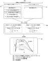
図4は、本発明による自動分析装置における、光量データ解析による劣化部品特定、又は、寿命品劣化検知の例である。
あらかじめ実験的に光学フィルターやランプといった寿命品の劣化による波長に対する透過光量の減少特性を調査しておき、既知のフィルター劣化時の透過光量分布(403)や、既知のランプ劣化時の透過光量分布(404)といった形でデータベース化しておく。
装置内の光量データ蓄積部(308)には、あらかじめ既知の透過光量分布(401)を格納しておく。さらに、使用先での装置据え付け時や部品交換時の初期データとして、当該装置の据え付け直後の透過光量分布(406)も、光量データ蓄積部(308)に格納しておく。
既知のフィルター劣化時の透過光量分布(403)は、既知の初期透過光量分布(402)に対して、波長によって透過光量の減少特性が異なる傾向がある。また、既知のランプ劣化時の透過光量分布(404)は、波長による透過光量の減少特性は波長によらず均一な傾向がある。そのため、当該装置にて直前に測定した透過光量分布(407)と、当該装置の据え付け直後の透過光量分布(406)から、透過光の減少傾向を解析することで、劣化原因の部品を特定し、切り分けることができる。
そこで、当該装置の透過光量分布(405)と既知の透過光量分布(401)に対して、波形相関度演算部(408)によって解析することで、ユーザーへの情報提供画面(409)にて、劣化部品の特定や寿命品情報として寿命の度合いについて情報提供可能である。
また、寿命部品の準備度合いについて使用者があらかじめ把握することが可能となる。
このように、制御部は、複数部品の個々の部品に対する、初期の透過光量分布と劣化時の透過光量分布、並びに、装置の据え付け直後の透過光量分布から、これらの分布の相関度を算出し、制御部は、測定時の透過光度分布と当該相関度に基づき、個々の劣化度合いを出力することができる。
なお、複数部品は、前記光源の光軸上に配置された部品であり、光学フィルターやランプの他、後述する被測定物質を収容する反応容器と前記反応容器を保温する保温媒体についても適用することができ、他の組み合わせや、これらの組み合わせについても適用できる。
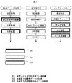
図5は、本発明による自動分析装置における、相関度および劣化度計算のアルゴリズムの例である。
例として光学フィルターおよびランプの劣化に関する演算を説明する。
あらかじめ実験的に求め保持しておくデータベース(501)として、初期の透過光分布、光学フィルターおよびランプ劣化時の各透過光分布、メーカー側として交換を推奨する限界の各透過光分布を備える。
また各々の自動分析装置では、リアルタイムに取得したデータ(502)として、現在の透過光分布を備える。
これらのデーターより、リアルタイムな演算内容(503)に示すような、現在の透過光分布と、各部品劣化時の透過光分布の相関を演算し、さらに現在の状態が各部品がどのくらいの劣化度であるかを、演算する。
その結果、各部品の劣化度を3つの現在の透過光分布条件で計算した例を、演算結果例(504)として示す。
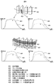
図6は、本発明による自動分析装置における、他に異常検出が期待できる現象の例である。
他に検出可能な情報としては、反応容器(601)の劣化および、保温媒体(607)の汚濁の検出が期待できる。
反応容器(601)に物理的な傷(603)が生じると、傷の無い反応容器(a)の透過光量分布(605)に比べて、傷のある反応容器(b)の透過光量分布(606)は、透過光量の低い傾向となる。図4において説明したランプやフィルターの劣化は、ランプの光軸(602)を通過する全ての反応容器を透過した透過光量分布に対して、一様の透過光量低下の特性を示すが、単独の反応容器の異常の場合は、当該反応容器の透過光量において特徴的な光量低下の特性を示すため、同一時間帯の隣接する反応容器どうしの透過光量分布を比較することで、個々の反応容器に着目して異常を検出することもできる。
また、保温媒体が腐敗などすることにより濁った場合、光度計のダイナミックレンジ低下により、分析精度の低下につながる影響が出てしまう。汚濁した保温媒体(607)において、透過光量の比較を行った場合、反応容器(e)の透過光量分布(608)と、隣接した反応容器(f)の透過光量分布(609)は、初期の透過光量分布(604)に比べて、同じ程度の光量低下の特性を示すため、前記の個々の反応容器の異常検出と区別することが可能となる。
このような性質を利用して、劣化部品の特定や劣化度合いを出力することができる。
図7は、本発明による自動分析装置における、データー取得タイミングの例である。
装置シリーズでの基礎データー取得(701)は、装置シリーズの一般特性として、通常時と部品異常時のデータベース構築のために取得するものである。各装置での瞬時データーの取得(702)は、現在の寿命度合いや異常の有無を確認するためのデーター取得である。各装置での状態更新後のデーター取得(703)は、その装置特有の透過光度分布を取得するもので、装置据え付け完了後に、当該装置の初期の透過光量分布として保持するために、データを取得する。また、各寿命品の交換時などで状態が変わった際も取得し、保持している初期の透過光分布データとの置き換えを行う。
101.搬送ライン
102.ローター
103.試薬ディスク
104.反応ディスク
105.分注機構
106.攪拌機構
107.分光器
110.検体容器
111.検体ラック
112.反応容器
113.試薬容器
114.シールド部
115.制御部
201.自動分析装置
204.分析部
206.反応液
208.反応容器
212.反応槽
213.保温媒体
215.反応ディスク
216.反応ディスクモーター
217.光源
218.分光器
220.光学フィルター
301.透過光
302.分光器
303.発光部
304.Logアンプ
305.光度信号処理部
307.AD変換器
308.光量データー蓄積部
309.CPU
401.既知の透過光量分布
402.既知の初期透過光量分布
403.既知のフィルター劣化時の透過光量分布
404.既知のランプ劣化時の透過光量分布
405.当該装置の透過光量分布
406.当該装置の据え付け直後の透過光量分布
407.直近に測定した透過光量分布
408.波形相関度演算部
409.ユーザーへの情報提供画面
501.あらかじめ実験的に求め保持しておくデータベース
502.リアルタイムに取得したデーター
503.リアルタイムな演算内容
504.演算結果例
601.反応容器
602.ランプの光軸
603.反応容器の物理的な傷
604.初期の透過光量分布
605.傷が無い反応容器(a)の透過光量分布
606.傷のある反応容器(b)の透過光量分布
607.汚濁した保温媒体
608.反応容器(e)の透過光量分布
609.反応容器(f)の透過光量分布
701.装置シリーズでの基礎データー取得
702.各装置での瞬時データーの取得
703.各装置での状態更新後のデーター取得
Claims (6)
- 光源から被測定物質を透過した透過光の測定時に、受光素子にて検出した複数波長の透過光度分布を記憶するデータ蓄積部と、
予め前記データ蓄積部に蓄えておいた第1透過光度分布と、測定時に取得した第2透過光度分布とを比較する制御部と、を備え、
前記制御部は、比較結果から複数部品の中から劣化部品を特定し、出力することを特徴とする自動分析装置。 - 請求項1記載の自動分析装置において、
前記複数の部品は、前記光源の光軸上に配置された部品であることを特徴とする自動分析装置。 - 請求項2記載の自動分析装置において、
前記複数部品は、前記光源と前記光軸上に配置された光学フィルター、又は、前記被測定物質を収容する反応容器と前記反応容器を保温する保温媒体の、いずれかの組み合わせを含むことを特徴とする自動分析装置。 - 請求項3記載の自動分析装置において、
前記制御部は、前記複数部品の個々の劣化度合いを出力することを特徴とする自動分析装置。 - 請求項4記載の自動分析装置において、
前記劣化度合いを表示する表示装置を備え、所定の劣化度合いになった場合に、前記表示装置にアラーム表示することを特徴とする自動分析装置。 - 請求項3記載の自動分析装置において、
前記制御部は、前記第1透過光度分布は、前記複数部品の個々の部品に対する、初期の透過光量分布と劣化時の透過光量分布、並びに、装置の据え付け直後の透過光量分布からなり、これらの分布の相関度を算出し、
前記制御部は、前記第2透過光度分布と当該相関度に基づき、前記個々の劣化度合いを出力することを特徴とする自動分析装置。
Priority Applications (3)
| Application Number | Priority Date | Filing Date | Title |
|---|---|---|---|
| EP14746842.5A EP2952879B1 (en) | 2013-01-31 | 2014-01-22 | Automatic analyzer |
| US14/762,922 US9575083B2 (en) | 2013-01-31 | 2014-01-22 | Automatic analysis apparatus |
| CN201480005796.8A CN104937393B (zh) | 2013-01-31 | 2014-01-22 | 自动分析装置 |
Applications Claiming Priority (2)
| Application Number | Priority Date | Filing Date | Title |
|---|---|---|---|
| JP2013-016321 | 2013-01-31 | ||
| JP2013016321A JP6129568B2 (ja) | 2013-01-31 | 2013-01-31 | 自動分析装置 |
Publications (1)
| Publication Number | Publication Date |
|---|---|
| WO2014119435A1 true WO2014119435A1 (ja) | 2014-08-07 |
Family
ID=51262149
Family Applications (1)
| Application Number | Title | Priority Date | Filing Date |
|---|---|---|---|
| PCT/JP2014/051172 WO2014119435A1 (ja) | 2013-01-31 | 2014-01-22 | 自動分析装置 |
Country Status (5)
| Country | Link |
|---|---|
| US (1) | US9575083B2 (ja) |
| EP (1) | EP2952879B1 (ja) |
| JP (1) | JP6129568B2 (ja) |
| CN (1) | CN104937393B (ja) |
| WO (1) | WO2014119435A1 (ja) |
Families Citing this family (4)
| Publication number | Priority date | Publication date | Assignee | Title |
|---|---|---|---|---|
| JP6658091B2 (ja) * | 2016-02-29 | 2020-03-04 | 株式会社島津製作所 | 分析測定装置システム |
| JP6984740B2 (ja) * | 2018-04-16 | 2021-12-22 | 株式会社島津製作所 | 吸光度検出器、液体クロマトグラフ及び異常判定方法 |
| WO2020148842A1 (ja) * | 2019-01-16 | 2020-07-23 | 株式会社島津製作所 | 吸光度検出器、クロマトグラフおよび光源交換時期管理方法 |
| CN115541897A (zh) * | 2021-06-30 | 2022-12-30 | 深圳市帝迈生物技术有限公司 | 血液分析仪预警方法和血液分析仪 |
Citations (7)
| Publication number | Priority date | Publication date | Assignee | Title |
|---|---|---|---|---|
| JPS64451A (en) * | 1987-02-20 | 1989-01-05 | Nittec Co Ltd | Method and instrument for optical measurement with automatic analysis device |
| JPH0777492A (ja) * | 1993-09-07 | 1995-03-20 | Toa Denpa Kogyo Kk | 吸光光度計およびこの吸光光度計の自己診断方法 |
| JPH09229939A (ja) | 1996-02-22 | 1997-09-05 | Hitachi Ltd | 自動化学分析装置における測光系の精度確認方法 |
| JPH11342123A (ja) * | 1998-06-03 | 1999-12-14 | Omron Corp | 非侵襲生体成分測定装置 |
| JP2004251802A (ja) * | 2003-02-21 | 2004-09-09 | Toshiba Corp | 自動分析装置 |
| JP2010243222A (ja) * | 2009-04-02 | 2010-10-28 | Hitachi High-Technologies Corp | 自動分析装置 |
| JP2011117746A (ja) | 2009-12-01 | 2011-06-16 | Hitachi High-Technologies Corp | 自動分析装置、および自動分析装置の光源ランプ交換方法 |
Family Cites Families (8)
| Publication number | Priority date | Publication date | Assignee | Title |
|---|---|---|---|---|
| JPH04204253A (ja) * | 1990-11-30 | 1992-07-24 | Hitachi Cable Ltd | 電線・ケーブルの劣化診断法 |
| JP3860846B2 (ja) * | 1994-02-25 | 2006-12-20 | 株式会社日立製作所 | 材料の劣化度測定システムおよび測定装置 |
| JPH09222393A (ja) * | 1996-02-16 | 1997-08-26 | Hitachi Ltd | 劣化度診断装置 |
| TW343281B (en) * | 1996-06-28 | 1998-10-21 | Hitachi Ltd | Method and apparatus for diagnosing degradation of an electric machine |
| JP2009047545A (ja) * | 2007-08-20 | 2009-03-05 | Olympus Corp | 分析装置および光源劣化検出方法 |
| JP4654256B2 (ja) * | 2008-02-28 | 2011-03-16 | 株式会社日立ハイテクノロジーズ | 自動分析装置 |
| JP5124498B2 (ja) * | 2009-01-30 | 2013-01-23 | 株式会社日立ハイテクノロジーズ | 自動分析装置 |
| JP5667757B2 (ja) * | 2009-11-04 | 2015-02-12 | トヨタホーム株式会社 | 建物外観の劣化診断方法及び建物外観の劣化診断システム |
-
2013
- 2013-01-31 JP JP2013016321A patent/JP6129568B2/ja active Active
-
2014
- 2014-01-22 WO PCT/JP2014/051172 patent/WO2014119435A1/ja active Application Filing
- 2014-01-22 US US14/762,922 patent/US9575083B2/en active Active
- 2014-01-22 EP EP14746842.5A patent/EP2952879B1/en active Active
- 2014-01-22 CN CN201480005796.8A patent/CN104937393B/zh active Active
Patent Citations (7)
| Publication number | Priority date | Publication date | Assignee | Title |
|---|---|---|---|---|
| JPS64451A (en) * | 1987-02-20 | 1989-01-05 | Nittec Co Ltd | Method and instrument for optical measurement with automatic analysis device |
| JPH0777492A (ja) * | 1993-09-07 | 1995-03-20 | Toa Denpa Kogyo Kk | 吸光光度計およびこの吸光光度計の自己診断方法 |
| JPH09229939A (ja) | 1996-02-22 | 1997-09-05 | Hitachi Ltd | 自動化学分析装置における測光系の精度確認方法 |
| JPH11342123A (ja) * | 1998-06-03 | 1999-12-14 | Omron Corp | 非侵襲生体成分測定装置 |
| JP2004251802A (ja) * | 2003-02-21 | 2004-09-09 | Toshiba Corp | 自動分析装置 |
| JP2010243222A (ja) * | 2009-04-02 | 2010-10-28 | Hitachi High-Technologies Corp | 自動分析装置 |
| JP2011117746A (ja) | 2009-12-01 | 2011-06-16 | Hitachi High-Technologies Corp | 自動分析装置、および自動分析装置の光源ランプ交換方法 |
Non-Patent Citations (1)
| Title |
|---|
| See also references of EP2952879A4 |
Also Published As
| Publication number | Publication date |
|---|---|
| JP2014149155A (ja) | 2014-08-21 |
| CN104937393A (zh) | 2015-09-23 |
| CN104937393B (zh) | 2018-01-02 |
| EP2952879B1 (en) | 2022-10-12 |
| JP6129568B2 (ja) | 2017-05-17 |
| EP2952879A1 (en) | 2015-12-09 |
| US9575083B2 (en) | 2017-02-21 |
| US20150369831A1 (en) | 2015-12-24 |
| EP2952879A4 (en) | 2016-10-26 |
Similar Documents
| Publication | Publication Date | Title |
|---|---|---|
| US8373861B2 (en) | System for rapid analysis of microbiological materials in liquid samples | |
| JP4654256B2 (ja) | 自動分析装置 | |
| CA2607086C (en) | System for rapid analysis of microbiological materials in liquid samples | |
| US7688448B2 (en) | Through-container optical evaluation system | |
| EP3182096B1 (en) | Calibration and/or error detection in an optical measurement device for biological samples | |
| US9400247B2 (en) | Automatic analyzer | |
| WO2015029595A1 (ja) | 核酸分析装置およびその装置診断方法 | |
| WO2014119435A1 (ja) | 自動分析装置 | |
| JPWO2010067513A1 (ja) | 自動分析装置 | |
| JP5932540B2 (ja) | 自動分析装置 | |
| RU2316755C2 (ru) | Способ и спектрометр для количественного определения компонента в образце | |
| JP7401993B2 (ja) | 検査室用機器内の検出ユニットの検出器によって測定された信号光強度を補正する方法 | |
| EP3514548B1 (en) | Automatic analysis apparatus | |
| JP4825442B2 (ja) | 臨床検査用自動分析装置の精度管理方法、及び自動分析装置 | |
| WO2023013344A1 (ja) | 化学分析装置 | |
| US10458997B2 (en) | Signal offset determination and correction | |
| JPH0660903B2 (ja) | 自動化学分析装置 | |
| JP6476275B2 (ja) | 分析装置およびその分析方法 | |
| JP5919218B2 (ja) | 核酸分析装置及び核酸分析方法 | |
| CN113777333A (zh) | 自动分析仪及其反应杯污染的判定方法和存储介质 | |
| JP2008203008A (ja) | 自動分析装置 | |
| JP2013024746A (ja) | 自動分析装置 | |
| WO2022019064A1 (ja) | 自動分析装置および自動分析方法 | |
| CN116165150A (zh) | 样本分析仪、样本分析仪的信号采集方法 | |
| JP2007240181A (ja) | 医用分析装置 |
Legal Events
| Date | Code | Title | Description |
|---|---|---|---|
| 121 | Ep: the epo has been informed by wipo that ep was designated in this application |
Ref document number: 14746842 Country of ref document: EP Kind code of ref document: A1 |
|
| WWE | Wipo information: entry into national phase |
Ref document number: 14762922 Country of ref document: US Ref document number: 2014746842 Country of ref document: EP |
|
| NENP | Non-entry into the national phase |
Ref country code: DE |