WO2014119432A1 - 連続重合装置、重合体組成物の製造方法およびインジェクションバルブ - Google Patents
連続重合装置、重合体組成物の製造方法およびインジェクションバルブ Download PDFInfo
- Publication number
- WO2014119432A1 WO2014119432A1 PCT/JP2014/051159 JP2014051159W WO2014119432A1 WO 2014119432 A1 WO2014119432 A1 WO 2014119432A1 JP 2014051159 W JP2014051159 W JP 2014051159W WO 2014119432 A1 WO2014119432 A1 WO 2014119432A1
- Authority
- WO
- WIPO (PCT)
- Prior art keywords
- reactor
- polymerization
- raw material
- material monomer
- temperature
- Prior art date
Links
- 238000006116 polymerization reaction Methods 0.000 title claims abstract description 370
- 238000002347 injection Methods 0.000 title claims abstract description 76
- 239000007924 injection Substances 0.000 title claims abstract description 76
- 239000000203 mixture Substances 0.000 title claims description 222
- 229920000642 polymer Polymers 0.000 title claims description 140
- 238000004519 manufacturing process Methods 0.000 title claims description 46
- 239000000178 monomer Substances 0.000 claims abstract description 254
- 239000003505 polymerization initiator Substances 0.000 claims abstract description 144
- 239000012530 fluid Substances 0.000 claims abstract description 65
- 239000002994 raw material Substances 0.000 claims description 232
- 238000006243 chemical reaction Methods 0.000 claims description 132
- 239000003112 inhibitor Substances 0.000 claims description 38
- 238000001816 cooling Methods 0.000 claims description 36
- 238000000605 extraction Methods 0.000 claims description 29
- 238000012662 bulk polymerization Methods 0.000 claims description 18
- 238000002156 mixing Methods 0.000 claims description 16
- 238000000034 method Methods 0.000 claims description 13
- 238000001514 detection method Methods 0.000 claims description 10
- 239000007858 starting material Substances 0.000 abstract 2
- 239000011342 resin composition Substances 0.000 description 36
- -1 Alkyl methacrylate Chemical compound 0.000 description 24
- 230000003068 static effect Effects 0.000 description 17
- 238000010528 free radical solution polymerization reaction Methods 0.000 description 13
- 238000011084 recovery Methods 0.000 description 13
- 239000006096 absorbing agent Substances 0.000 description 12
- 239000002609 medium Substances 0.000 description 12
- 239000000047 product Substances 0.000 description 12
- 239000002904 solvent Substances 0.000 description 12
- 235000014113 dietary fatty acids Nutrition 0.000 description 11
- 229930195729 fatty acid Natural products 0.000 description 11
- 239000000194 fatty acid Substances 0.000 description 11
- 238000003756 stirring Methods 0.000 description 11
- 239000012986 chain transfer agent Substances 0.000 description 9
- 239000003795 chemical substances by application Substances 0.000 description 9
- 239000000499 gel Substances 0.000 description 9
- 239000012760 heat stabilizer Substances 0.000 description 9
- 230000001276 controlling effect Effects 0.000 description 8
- 150000004665 fatty acids Chemical class 0.000 description 8
- 239000012535 impurity Substances 0.000 description 8
- 239000003999 initiator Substances 0.000 description 8
- 239000007788 liquid Substances 0.000 description 8
- 150000003254 radicals Chemical class 0.000 description 7
- 239000006097 ultraviolet radiation absorber Substances 0.000 description 7
- JHPBZFOKBAGZBL-UHFFFAOYSA-N (3-hydroxy-2,2,4-trimethylpentyl) 2-methylprop-2-enoate Chemical compound CC(C)C(O)C(C)(C)COC(=O)C(C)=C JHPBZFOKBAGZBL-UHFFFAOYSA-N 0.000 description 6
- UKMSUNONTOPOIO-UHFFFAOYSA-N docosanoic acid Chemical compound CCCCCCCCCCCCCCCCCCCCCC(O)=O UKMSUNONTOPOIO-UHFFFAOYSA-N 0.000 description 6
- 235000019441 ethanol Nutrition 0.000 description 6
- 125000005397 methacrylic acid ester group Chemical group 0.000 description 6
- 238000000354 decomposition reaction Methods 0.000 description 5
- 238000001746 injection moulding Methods 0.000 description 5
- 238000000465 moulding Methods 0.000 description 5
- 239000011541 reaction mixture Substances 0.000 description 5
- LFQSCWFLJHTTHZ-UHFFFAOYSA-N Ethanol Chemical compound CCO LFQSCWFLJHTTHZ-UHFFFAOYSA-N 0.000 description 4
- HPEUJPJOZXNMSJ-UHFFFAOYSA-N Methyl stearate Chemical compound CCCCCCCCCCCCCCCCCC(=O)OC HPEUJPJOZXNMSJ-UHFFFAOYSA-N 0.000 description 4
- OFOBLEOULBTSOW-UHFFFAOYSA-N Propanedioic acid Natural products OC(=O)CC(O)=O OFOBLEOULBTSOW-UHFFFAOYSA-N 0.000 description 4
- PPBRXRYQALVLMV-UHFFFAOYSA-N Styrene Chemical compound C=CC1=CC=CC=C1 PPBRXRYQALVLMV-UHFFFAOYSA-N 0.000 description 4
- 125000004432 carbon atom Chemical group C* 0.000 description 4
- POULHZVOKOAJMA-UHFFFAOYSA-N dodecanoic acid Chemical compound CCCCCCCCCCCC(O)=O POULHZVOKOAJMA-UHFFFAOYSA-N 0.000 description 4
- MVLVMROFTAUDAG-UHFFFAOYSA-N ethyl octadecanoate Chemical compound CCCCCCCCCCCCCCCCCC(=O)OCC MVLVMROFTAUDAG-UHFFFAOYSA-N 0.000 description 4
- 238000010438 heat treatment Methods 0.000 description 4
- BXWNKGSJHAJOGX-UHFFFAOYSA-N hexadecan-1-ol Chemical compound CCCCCCCCCCCCCCCCO BXWNKGSJHAJOGX-UHFFFAOYSA-N 0.000 description 4
- IPCSVZSSVZVIGE-UHFFFAOYSA-N hexadecanoic acid Chemical compound CCCCCCCCCCCCCCCC(O)=O IPCSVZSSVZVIGE-UHFFFAOYSA-N 0.000 description 4
- GLDOVTGHNKAZLK-UHFFFAOYSA-N octadecan-1-ol Chemical compound CCCCCCCCCCCCCCCCCCO GLDOVTGHNKAZLK-UHFFFAOYSA-N 0.000 description 4
- 239000008188 pellet Substances 0.000 description 4
- 235000021122 unsaturated fatty acids Nutrition 0.000 description 4
- 125000000391 vinyl group Chemical group [H]C([*])=C([H])[H] 0.000 description 4
- 235000021357 Behenic acid Nutrition 0.000 description 3
- RWSOTUBLDIXVET-UHFFFAOYSA-N Dihydrogen sulfide Chemical class S RWSOTUBLDIXVET-UHFFFAOYSA-N 0.000 description 3
- LYCAIKOWRPUZTN-UHFFFAOYSA-N Ethylene glycol Chemical compound OCCO LYCAIKOWRPUZTN-UHFFFAOYSA-N 0.000 description 3
- OKKJLVBELUTLKV-UHFFFAOYSA-N Methanol Chemical compound OC OKKJLVBELUTLKV-UHFFFAOYSA-N 0.000 description 3
- VVQNEPGJFQJSBK-UHFFFAOYSA-N Methyl methacrylate Chemical compound COC(=O)C(C)=C VVQNEPGJFQJSBK-UHFFFAOYSA-N 0.000 description 3
- 235000021355 Stearic acid Nutrition 0.000 description 3
- YXFVVABEGXRONW-UHFFFAOYSA-N Toluene Chemical compound CC1=CC=CC=C1 YXFVVABEGXRONW-UHFFFAOYSA-N 0.000 description 3
- 125000000217 alkyl group Chemical group 0.000 description 3
- 229940116226 behenic acid Drugs 0.000 description 3
- QRUDEWIWKLJBPS-UHFFFAOYSA-N benzotriazole Chemical compound C1=CC=C2N[N][N]C2=C1 QRUDEWIWKLJBPS-UHFFFAOYSA-N 0.000 description 3
- 239000012964 benzotriazole Substances 0.000 description 3
- 238000009826 distribution Methods 0.000 description 3
- 238000011049 filling Methods 0.000 description 3
- 239000007789 gas Substances 0.000 description 3
- FUZZWVXGSFPDMH-UHFFFAOYSA-N hexanoic acid Chemical compound CCCCCC(O)=O FUZZWVXGSFPDMH-UHFFFAOYSA-N 0.000 description 3
- FTWUXYZHDFCGSV-UHFFFAOYSA-N n,n'-diphenyloxamide Chemical compound C=1C=CC=CC=1NC(=O)C(=O)NC1=CC=CC=C1 FTWUXYZHDFCGSV-UHFFFAOYSA-N 0.000 description 3
- QIQXTHQIDYTFRH-UHFFFAOYSA-N octadecanoic acid Chemical compound CCCCCCCCCCCCCCCCCC(O)=O QIQXTHQIDYTFRH-UHFFFAOYSA-N 0.000 description 3
- OQCDKBAXFALNLD-UHFFFAOYSA-N octadecanoic acid Natural products CCCCCCCC(C)CCCCCCCCC(O)=O OQCDKBAXFALNLD-UHFFFAOYSA-N 0.000 description 3
- 230000000704 physical effect Effects 0.000 description 3
- 239000008117 stearic acid Substances 0.000 description 3
- 239000006188 syrup Substances 0.000 description 3
- 235000020357 syrup Nutrition 0.000 description 3
- 125000000999 tert-butyl group Chemical group [H]C([H])([H])C(*)(C([H])([H])[H])C([H])([H])[H] 0.000 description 3
- RMVRSNDYEFQCLF-UHFFFAOYSA-N thiophenol Chemical compound SC1=CC=CC=C1 RMVRSNDYEFQCLF-UHFFFAOYSA-N 0.000 description 3
- 229920002554 vinyl polymer Polymers 0.000 description 3
- FEODVXCWZVOEIR-UHFFFAOYSA-N (2,4-ditert-butylphenyl) octyl hydrogen phosphite Chemical compound CCCCCCCCOP(O)OC1=CC=C(C(C)(C)C)C=C1C(C)(C)C FEODVXCWZVOEIR-UHFFFAOYSA-N 0.000 description 2
- WRIDQFICGBMAFQ-UHFFFAOYSA-N (E)-8-Octadecenoic acid Natural products CCCCCCCCCC=CCCCCCCC(O)=O WRIDQFICGBMAFQ-UHFFFAOYSA-N 0.000 description 2
- QMMJWQMCMRUYTG-UHFFFAOYSA-N 1,2,4,5-tetrachloro-3-(trifluoromethyl)benzene Chemical compound FC(F)(F)C1=C(Cl)C(Cl)=CC(Cl)=C1Cl QMMJWQMCMRUYTG-UHFFFAOYSA-N 0.000 description 2
- MYRTYDVEIRVNKP-UHFFFAOYSA-N 1,2-Divinylbenzene Chemical compound C=CC1=CC=CC=C1C=C MYRTYDVEIRVNKP-UHFFFAOYSA-N 0.000 description 2
- PMBXCGGQNSVESQ-UHFFFAOYSA-N 1-Hexanethiol Chemical compound CCCCCCS PMBXCGGQNSVESQ-UHFFFAOYSA-N 0.000 description 2
- ULQISTXYYBZJSJ-UHFFFAOYSA-N 12-hydroxyoctadecanoic acid Chemical compound CCCCCCC(O)CCCCCCCCCCC(O)=O ULQISTXYYBZJSJ-UHFFFAOYSA-N 0.000 description 2
- WNWHHMBRJJOGFJ-UHFFFAOYSA-N 16-methylheptadecan-1-ol Chemical compound CC(C)CCCCCCCCCCCCCCCO WNWHHMBRJJOGFJ-UHFFFAOYSA-N 0.000 description 2
- OZAIFHULBGXAKX-UHFFFAOYSA-N 2-(2-cyanopropan-2-yldiazenyl)-2-methylpropanenitrile Chemical compound N#CC(C)(C)N=NC(C)(C)C#N OZAIFHULBGXAKX-UHFFFAOYSA-N 0.000 description 2
- QTWKINKGAHTPFJ-UHFFFAOYSA-N 2-(butan-2-yldisulfanyl)butane Chemical compound CCC(C)SSC(C)CC QTWKINKGAHTPFJ-UHFFFAOYSA-N 0.000 description 2
- LQJBNNIYVWPHFW-UHFFFAOYSA-N 20:1omega9c fatty acid Natural products CCCCCCCCCCC=CCCCCCCCC(O)=O LQJBNNIYVWPHFW-UHFFFAOYSA-N 0.000 description 2
- QSBYPNXLFMSGKH-UHFFFAOYSA-N 9-Heptadecensaeure Natural products CCCCCCCC=CCCCCCCCC(O)=O QSBYPNXLFMSGKH-UHFFFAOYSA-N 0.000 description 2
- KAKZBPTYRLMSJV-UHFFFAOYSA-N Butadiene Chemical compound C=CC=C KAKZBPTYRLMSJV-UHFFFAOYSA-N 0.000 description 2
- SOGAXMICEFXMKE-UHFFFAOYSA-N Butylmethacrylate Chemical compound CCCCOC(=O)C(C)=C SOGAXMICEFXMKE-UHFFFAOYSA-N 0.000 description 2
- 229920001651 Cyanoacrylate Polymers 0.000 description 2
- CETBSQOFQKLHHZ-UHFFFAOYSA-N Diethyl disulfide Chemical compound CCSSCC CETBSQOFQKLHHZ-UHFFFAOYSA-N 0.000 description 2
- YNQLUTRBYVCPMQ-UHFFFAOYSA-N Ethylbenzene Chemical compound CCC1=CC=CC=C1 YNQLUTRBYVCPMQ-UHFFFAOYSA-N 0.000 description 2
- QIGBRXMKCJKVMJ-UHFFFAOYSA-N Hydroquinone Chemical compound OC1=CC=C(O)C=C1 QIGBRXMKCJKVMJ-UHFFFAOYSA-N 0.000 description 2
- 239000005639 Lauric acid Substances 0.000 description 2
- BAPJBEWLBFYGME-UHFFFAOYSA-N Methyl acrylate Chemical compound COC(=O)C=C BAPJBEWLBFYGME-UHFFFAOYSA-N 0.000 description 2
- MWCLLHOVUTZFKS-UHFFFAOYSA-N Methyl cyanoacrylate Chemical compound COC(=O)C(=C)C#N MWCLLHOVUTZFKS-UHFFFAOYSA-N 0.000 description 2
- FLIACVVOZYBSBS-UHFFFAOYSA-N Methyl palmitate Chemical compound CCCCCCCCCCCCCCCC(=O)OC FLIACVVOZYBSBS-UHFFFAOYSA-N 0.000 description 2
- 239000005642 Oleic acid Substances 0.000 description 2
- ZQPPMHVWECSIRJ-UHFFFAOYSA-N Oleic acid Natural products CCCCCCCCC=CCCCCCCCC(O)=O ZQPPMHVWECSIRJ-UHFFFAOYSA-N 0.000 description 2
- 235000021314 Palmitic acid Nutrition 0.000 description 2
- OAICVXFJPJFONN-UHFFFAOYSA-N Phosphorus Chemical compound [P] OAICVXFJPJFONN-UHFFFAOYSA-N 0.000 description 2
- BQCADISMDOOEFD-UHFFFAOYSA-N Silver Chemical compound [Ag] BQCADISMDOOEFD-UHFFFAOYSA-N 0.000 description 2
- MOYAFQVGZZPNRA-UHFFFAOYSA-N Terpinolene Chemical compound CC(C)=C1CCC(C)=CC1 MOYAFQVGZZPNRA-UHFFFAOYSA-N 0.000 description 2
- 239000002253 acid Substances 0.000 description 2
- 150000001408 amides Chemical class 0.000 description 2
- RWCCWEUUXYIKHB-UHFFFAOYSA-N benzophenone Chemical compound C=1C=CC=CC=1C(=O)C1=CC=CC=C1 RWCCWEUUXYIKHB-UHFFFAOYSA-N 0.000 description 2
- 239000012965 benzophenone Substances 0.000 description 2
- VBICKXHEKHSIBG-UHFFFAOYSA-N beta-monoglyceryl stearate Natural products CCCCCCCCCCCCCCCCCC(=O)OCC(O)CO VBICKXHEKHSIBG-UHFFFAOYSA-N 0.000 description 2
- LEDIWWJKWAMGLD-UHFFFAOYSA-N bis(2-methylundecan-2-yl) disulfide Chemical compound CCCCCCCCCC(C)(C)SSC(C)(C)CCCCCCCCC LEDIWWJKWAMGLD-UHFFFAOYSA-N 0.000 description 2
- WQAQPCDUOCURKW-UHFFFAOYSA-N butanethiol Chemical compound CCCCS WQAQPCDUOCURKW-UHFFFAOYSA-N 0.000 description 2
- GLYJVQDYLFAUFC-UHFFFAOYSA-N butyl hexadecanoate Chemical compound CCCCCCCCCCCCCCCC(=O)OCCCC GLYJVQDYLFAUFC-UHFFFAOYSA-N 0.000 description 2
- 150000001735 carboxylic acids Chemical class 0.000 description 2
- 229960000541 cetyl alcohol Drugs 0.000 description 2
- 238000004040 coloring Methods 0.000 description 2
- NNBZCPXTIHJBJL-UHFFFAOYSA-N decalin Chemical compound C1CCCC2CCCCC21 NNBZCPXTIHJBJL-UHFFFAOYSA-N 0.000 description 2
- DIOQZVSQGTUSAI-UHFFFAOYSA-N decane Chemical compound CCCCCCCCCC DIOQZVSQGTUSAI-UHFFFAOYSA-N 0.000 description 2
- GHVNFZFCNZKVNT-UHFFFAOYSA-N decanoic acid Chemical compound CCCCCCCCCC(O)=O GHVNFZFCNZKVNT-UHFFFAOYSA-N 0.000 description 2
- ZQMIGQNCOMNODD-UHFFFAOYSA-N diacetyl peroxide Chemical compound CC(=O)OOC(C)=O ZQMIGQNCOMNODD-UHFFFAOYSA-N 0.000 description 2
- 239000000539 dimer Substances 0.000 description 2
- WQOXQRCZOLPYPM-UHFFFAOYSA-N dimethyl disulfide Chemical compound CSSC WQOXQRCZOLPYPM-UHFFFAOYSA-N 0.000 description 2
- DMBHHRLKUKUOEG-UHFFFAOYSA-N diphenylamine Chemical compound C=1C=CC=CC=1NC1=CC=CC=C1 DMBHHRLKUKUOEG-UHFFFAOYSA-N 0.000 description 2
- ALVPFGSHPUPROW-UHFFFAOYSA-N dipropyl disulfide Chemical compound CCCSSCCC ALVPFGSHPUPROW-UHFFFAOYSA-N 0.000 description 2
- NOPFSRXAKWQILS-UHFFFAOYSA-N docosan-1-ol Chemical compound CCCCCCCCCCCCCCCCCCCCCCO NOPFSRXAKWQILS-UHFFFAOYSA-N 0.000 description 2
- CAMHHLOGFDZBBG-UHFFFAOYSA-N epoxidized methyl oleate Natural products CCCCCCCCC1OC1CCCCCCCC(=O)OC CAMHHLOGFDZBBG-UHFFFAOYSA-N 0.000 description 2
- JIZCYLOUIAIZHQ-UHFFFAOYSA-N ethyl docosenyl Chemical compound CCCCCCCCCCCCCCCCCCCCCC(=O)OCC JIZCYLOUIAIZHQ-UHFFFAOYSA-N 0.000 description 2
- XIRNKXNNONJFQO-UHFFFAOYSA-N ethyl hexadecanoate Chemical compound CCCCCCCCCCCCCCCC(=O)OCC XIRNKXNNONJFQO-UHFFFAOYSA-N 0.000 description 2
- MMXKVMNBHPAILY-UHFFFAOYSA-N ethyl laurate Chemical compound CCCCCCCCCCCC(=O)OCC MMXKVMNBHPAILY-UHFFFAOYSA-N 0.000 description 2
- VKOBVWXKNCXXDE-UHFFFAOYSA-N icosanoic acid Chemical compound CCCCCCCCCCCCCCCCCCCC(O)=O VKOBVWXKNCXXDE-UHFFFAOYSA-N 0.000 description 2
- 238000009413 insulation Methods 0.000 description 2
- QXJSBBXBKPUZAA-UHFFFAOYSA-N isooleic acid Natural products CCCCCCCC=CCCCCCCCCC(O)=O QXJSBBXBKPUZAA-UHFFFAOYSA-N 0.000 description 2
- 229910052751 metal Inorganic materials 0.000 description 2
- 239000002184 metal Substances 0.000 description 2
- QSQLTHHMFHEFIY-UHFFFAOYSA-N methyl behenate Chemical compound CCCCCCCCCCCCCCCCCCCCCC(=O)OC QSQLTHHMFHEFIY-UHFFFAOYSA-N 0.000 description 2
- UQDUPQYQJKYHQI-UHFFFAOYSA-N methyl laurate Chemical compound CCCCCCCCCCCC(=O)OC UQDUPQYQJKYHQI-UHFFFAOYSA-N 0.000 description 2
- 239000006082 mold release agent Substances 0.000 description 2
- 239000012778 molding material Substances 0.000 description 2
- WQEPLUUGTLDZJY-UHFFFAOYSA-N n-Pentadecanoic acid Natural products CCCCCCCCCCCCCCC(O)=O WQEPLUUGTLDZJY-UHFFFAOYSA-N 0.000 description 2
- WIBFFTLQMKKBLZ-SEYXRHQNSA-N n-butyl oleate Chemical compound CCCCCCCC\C=C/CCCCCCCC(=O)OCCCC WIBFFTLQMKKBLZ-SEYXRHQNSA-N 0.000 description 2
- GOQYKNQRPGWPLP-UHFFFAOYSA-N n-heptadecyl alcohol Natural products CCCCCCCCCCCCCCCCCO GOQYKNQRPGWPLP-UHFFFAOYSA-N 0.000 description 2
- LYRFLYHAGKPMFH-UHFFFAOYSA-N octadecanamide Chemical compound CCCCCCCCCCCCCCCCCC(N)=O LYRFLYHAGKPMFH-UHFFFAOYSA-N 0.000 description 2
- WWZKQHOCKIZLMA-UHFFFAOYSA-N octanoic acid Chemical compound CCCCCCCC(O)=O WWZKQHOCKIZLMA-UHFFFAOYSA-N 0.000 description 2
- IIGMITQLXAGZTL-UHFFFAOYSA-N octyl octadecanoate Chemical compound CCCCCCCCCCCCCCCCCC(=O)OCCCCCCCC IIGMITQLXAGZTL-UHFFFAOYSA-N 0.000 description 2
- ZQPPMHVWECSIRJ-KTKRTIGZSA-N oleic acid Chemical compound CCCCCCCC\C=C/CCCCCCCC(O)=O ZQPPMHVWECSIRJ-KTKRTIGZSA-N 0.000 description 2
- SECPZKHBENQXJG-FPLPWBNLSA-N palmitoleic acid Chemical compound CCCCCC\C=C/CCCCCCCC(O)=O SECPZKHBENQXJG-FPLPWBNLSA-N 0.000 description 2
- PGMYKACGEOXYJE-UHFFFAOYSA-N pentyl acetate Chemical compound CCCCCOC(C)=O PGMYKACGEOXYJE-UHFFFAOYSA-N 0.000 description 2
- 229910052698 phosphorus Inorganic materials 0.000 description 2
- 239000011574 phosphorus Substances 0.000 description 2
- KJRCEJOSASVSRA-UHFFFAOYSA-N propane-2-thiol Chemical compound CC(C)S KJRCEJOSASVSRA-UHFFFAOYSA-N 0.000 description 2
- BEKZXQKGTDVSKX-UHFFFAOYSA-N propyl hexadecanoate Chemical compound CCCCCCCCCCCCCCCC(=O)OCCC BEKZXQKGTDVSKX-UHFFFAOYSA-N 0.000 description 2
- 230000001105 regulatory effect Effects 0.000 description 2
- 150000003839 salts Chemical class 0.000 description 2
- 229910052709 silver Inorganic materials 0.000 description 2
- 239000004332 silver Substances 0.000 description 2
- HLZKNKRTKFSKGZ-UHFFFAOYSA-N tetradecan-1-ol Chemical compound CCCCCCCCCCCCCCO HLZKNKRTKFSKGZ-UHFFFAOYSA-N 0.000 description 2
- CWERGRDVMFNCDR-UHFFFAOYSA-N thioglycolic acid Chemical compound OC(=O)CS CWERGRDVMFNCDR-UHFFFAOYSA-N 0.000 description 2
- VMPHSYLJUKZBJJ-UHFFFAOYSA-N trilaurin Chemical compound CCCCCCCCCCCC(=O)OCC(OC(=O)CCCCCCCCCCC)COC(=O)CCCCCCCCCCC VMPHSYLJUKZBJJ-UHFFFAOYSA-N 0.000 description 2
- 239000013638 trimer Substances 0.000 description 2
- HVLLSGMXQDNUAL-UHFFFAOYSA-N triphenyl phosphite Chemical compound C=1C=CC=CC=1OP(OC=1C=CC=CC=1)OC1=CC=CC=C1 HVLLSGMXQDNUAL-UHFFFAOYSA-N 0.000 description 2
- DCXXMTOCNZCJGO-UHFFFAOYSA-N tristearoylglycerol Chemical compound CCCCCCCCCCCCCCCCCC(=O)OCC(OC(=O)CCCCCCCCCCCCCCCCC)COC(=O)CCCCCCCCCCCCCCCCC DCXXMTOCNZCJGO-UHFFFAOYSA-N 0.000 description 2
- 150000004670 unsaturated fatty acids Chemical class 0.000 description 2
- WRXCBRHBHGNNQA-UHFFFAOYSA-N (2,4-dichlorobenzoyl) 2,4-dichlorobenzenecarboperoxoate Chemical compound ClC1=CC(Cl)=CC=C1C(=O)OOC(=O)C1=CC=C(Cl)C=C1Cl WRXCBRHBHGNNQA-UHFFFAOYSA-N 0.000 description 1
- SXJSETSRWNDWPP-UHFFFAOYSA-N (2-hydroxy-4-phenylmethoxyphenyl)-phenylmethanone Chemical compound C=1C=C(C(=O)C=2C=CC=CC=2)C(O)=CC=1OCC1=CC=CC=C1 SXJSETSRWNDWPP-UHFFFAOYSA-N 0.000 description 1
- FVQMJJQUGGVLEP-UHFFFAOYSA-N (2-methylpropan-2-yl)oxy 2-ethylhexaneperoxoate Chemical compound CCCCC(CC)C(=O)OOOC(C)(C)C FVQMJJQUGGVLEP-UHFFFAOYSA-N 0.000 description 1
- QEQBMZQFDDDTPN-UHFFFAOYSA-N (2-methylpropan-2-yl)oxy benzenecarboperoxoate Chemical compound CC(C)(C)OOOC(=O)C1=CC=CC=C1 QEQBMZQFDDDTPN-UHFFFAOYSA-N 0.000 description 1
- KDGNCLDCOVTOCS-UHFFFAOYSA-N (2-methylpropan-2-yl)oxy propan-2-yl carbonate Chemical compound CC(C)OC(=O)OOC(C)(C)C KDGNCLDCOVTOCS-UHFFFAOYSA-N 0.000 description 1
- ARVUDIQYNJVQIW-UHFFFAOYSA-N (4-dodecoxy-2-hydroxyphenyl)-phenylmethanone Chemical compound OC1=CC(OCCCCCCCCCCCC)=CC=C1C(=O)C1=CC=CC=C1 ARVUDIQYNJVQIW-UHFFFAOYSA-N 0.000 description 1
- NOBYOEQUFMGXBP-UHFFFAOYSA-N (4-tert-butylcyclohexyl) (4-tert-butylcyclohexyl)oxycarbonyloxy carbonate Chemical compound C1CC(C(C)(C)C)CCC1OC(=O)OOC(=O)OC1CCC(C(C)(C)C)CC1 NOBYOEQUFMGXBP-UHFFFAOYSA-N 0.000 description 1
- ALSTYHKOOCGGFT-KTKRTIGZSA-N (9Z)-octadecen-1-ol Chemical compound CCCCCCCC\C=C/CCCCCCCCO ALSTYHKOOCGGFT-KTKRTIGZSA-N 0.000 description 1
- OYHQOLUKZRVURQ-NTGFUMLPSA-N (9Z,12Z)-9,10,12,13-tetratritiooctadeca-9,12-dienoic acid Chemical compound C(CCCCCCC\C(=C(/C\C(=C(/CCCCC)\[3H])\[3H])\[3H])\[3H])(=O)O OYHQOLUKZRVURQ-NTGFUMLPSA-N 0.000 description 1
- 239000001149 (9Z,12Z)-octadeca-9,12-dienoate Substances 0.000 description 1
- WTTJVINHCBCLGX-UHFFFAOYSA-N (9trans,12cis)-methyl linoleate Natural products CCCCCC=CCC=CCCCCCCCC(=O)OC WTTJVINHCBCLGX-UHFFFAOYSA-N 0.000 description 1
- DNIAPMSPPWPWGF-GSVOUGTGSA-N (R)-(-)-Propylene glycol Chemical compound C[C@@H](O)CO DNIAPMSPPWPWGF-GSVOUGTGSA-N 0.000 description 1
- FYRCDEARNUVZRG-UHFFFAOYSA-N 1,1,5-trimethyl-3,3-bis(2-methylpentan-2-ylperoxy)cyclohexane Chemical compound CCCC(C)(C)OOC1(OOC(C)(C)CCC)CC(C)CC(C)(C)C1 FYRCDEARNUVZRG-UHFFFAOYSA-N 0.000 description 1
- QIMNMPKJEMBZKM-UHFFFAOYSA-N 1,1-bis(butylperoxy)cyclohexane Chemical compound CCCCOOC1(OOCCCC)CCCCC1 QIMNMPKJEMBZKM-UHFFFAOYSA-N 0.000 description 1
- NALFRYPTRXKZPN-UHFFFAOYSA-N 1,1-bis(tert-butylperoxy)-3,3,5-trimethylcyclohexane Chemical compound CC1CC(C)(C)CC(OOC(C)(C)C)(OOC(C)(C)C)C1 NALFRYPTRXKZPN-UHFFFAOYSA-N 0.000 description 1
- KOMNUTZXSVSERR-UHFFFAOYSA-N 1,3,5-tris(prop-2-enyl)-1,3,5-triazinane-2,4,6-trione Chemical compound C=CCN1C(=O)N(CC=C)C(=O)N(CC=C)C1=O KOMNUTZXSVSERR-UHFFFAOYSA-N 0.000 description 1
- DMBUODUULYCPAK-UHFFFAOYSA-N 1,3-bis(docosanoyloxy)propan-2-yl docosanoate Chemical compound CCCCCCCCCCCCCCCCCCCCCC(=O)OCC(OC(=O)CCCCCCCCCCCCCCCCCCCCC)COC(=O)CCCCCCCCCCCCCCCCCCCCC DMBUODUULYCPAK-UHFFFAOYSA-N 0.000 description 1
- FSWYUDLVKBSHDX-UHFFFAOYSA-N 1,4,5,8-tetrahydronaphthalene Chemical compound C1C=CCC2=C1CC=CC2 FSWYUDLVKBSHDX-UHFFFAOYSA-N 0.000 description 1
- HSOOIVBINKDISP-UHFFFAOYSA-N 1-(2-methylprop-2-enoyloxy)butyl 2-methylprop-2-enoate Chemical compound CC(=C)C(=O)OC(CCC)OC(=O)C(C)=C HSOOIVBINKDISP-UHFFFAOYSA-N 0.000 description 1
- GAYUSSOCODCSNF-UHFFFAOYSA-N 1-(dodecyldisulfanyl)dodecane Chemical compound CCCCCCCCCCCCSSCCCCCCCCCCCC GAYUSSOCODCSNF-UHFFFAOYSA-N 0.000 description 1
- WECGLUPZRHILCT-GSNKCQISSA-N 1-linoleoyl-sn-glycerol Chemical compound CCCCC\C=C/C\C=C/CCCCCCCC(=O)OC[C@@H](O)CO WECGLUPZRHILCT-GSNKCQISSA-N 0.000 description 1
- RZRNAYUHWVFMIP-KTKRTIGZSA-N 1-oleoylglycerol Chemical compound CCCCCCCC\C=C/CCCCCCCC(=O)OCC(O)CO RZRNAYUHWVFMIP-KTKRTIGZSA-N 0.000 description 1
- WJFKNYWRSNBZNX-UHFFFAOYSA-N 10H-phenothiazine Chemical compound C1=CC=C2NC3=CC=CC=C3SC2=C1 WJFKNYWRSNBZNX-UHFFFAOYSA-N 0.000 description 1
- ZIMCZOLRXKPXLN-UHFFFAOYSA-N 2,2,4-trimethyl-4-(2,4,4-trimethylpentan-2-yldisulfanyl)pentane Chemical compound CC(C)(C)CC(C)(C)SSC(C)(C)CC(C)(C)C ZIMCZOLRXKPXLN-UHFFFAOYSA-N 0.000 description 1
- YAJYJWXEWKRTPO-UHFFFAOYSA-N 2,3,3,4,4,5-hexamethylhexane-2-thiol Chemical compound CC(C)C(C)(C)C(C)(C)C(C)(C)S YAJYJWXEWKRTPO-UHFFFAOYSA-N 0.000 description 1
- OWPUOLBODXJOKH-UHFFFAOYSA-N 2,3-dihydroxypropyl prop-2-enoate Chemical compound OCC(O)COC(=O)C=C OWPUOLBODXJOKH-UHFFFAOYSA-N 0.000 description 1
- JWTVCTSPMWDTOF-UHFFFAOYSA-N 2,3-dimethylbutan-2-yloxy 2-ethylhexaneperoxoate Chemical compound CCCCC(CC)C(=O)OOOC(C)(C)C(C)C JWTVCTSPMWDTOF-UHFFFAOYSA-N 0.000 description 1
- BJELTSYBAHKXRW-UHFFFAOYSA-N 2,4,6-triallyloxy-1,3,5-triazine Chemical compound C=CCOC1=NC(OCC=C)=NC(OCC=C)=N1 BJELTSYBAHKXRW-UHFFFAOYSA-N 0.000 description 1
- ZXDDPOHVAMWLBH-UHFFFAOYSA-N 2,4-Dihydroxybenzophenone Chemical compound OC1=CC(O)=CC=C1C(=O)C1=CC=CC=C1 ZXDDPOHVAMWLBH-UHFFFAOYSA-N 0.000 description 1
- OPLCSTZDXXUYDU-UHFFFAOYSA-N 2,4-dimethyl-6-tert-butylphenol Chemical compound CC1=CC(C)=C(O)C(C(C)(C)C)=C1 OPLCSTZDXXUYDU-UHFFFAOYSA-N 0.000 description 1
- STMDPCBYJCIZOD-UHFFFAOYSA-N 2-(2,4-dinitroanilino)-4-methylpentanoic acid Chemical compound CC(C)CC(C(O)=O)NC1=CC=C([N+]([O-])=O)C=C1[N+]([O-])=O STMDPCBYJCIZOD-UHFFFAOYSA-N 0.000 description 1
- SMZOUWXMTYCWNB-UHFFFAOYSA-N 2-(2-methoxy-5-methylphenyl)ethanamine Chemical compound COC1=CC=C(C)C=C1CCN SMZOUWXMTYCWNB-UHFFFAOYSA-N 0.000 description 1
- JAHNSTQSQJOJLO-UHFFFAOYSA-N 2-(3-fluorophenyl)-1h-imidazole Chemical compound FC1=CC=CC(C=2NC=CN=2)=C1 JAHNSTQSQJOJLO-UHFFFAOYSA-N 0.000 description 1
- ZMWRRFHBXARRRT-UHFFFAOYSA-N 2-(benzotriazol-2-yl)-4,6-bis(2-methylbutan-2-yl)phenol Chemical compound CCC(C)(C)C1=CC(C(C)(C)CC)=CC(N2N=C3C=CC=CC3=N2)=C1O ZMWRRFHBXARRRT-UHFFFAOYSA-N 0.000 description 1
- LHPPDQUVECZQSW-UHFFFAOYSA-N 2-(benzotriazol-2-yl)-4,6-ditert-butylphenol Chemical compound CC(C)(C)C1=CC(C(C)(C)C)=CC(N2N=C3C=CC=CC3=N2)=C1O LHPPDQUVECZQSW-UHFFFAOYSA-N 0.000 description 1
- JKNCOURZONDCGV-UHFFFAOYSA-N 2-(dimethylamino)ethyl 2-methylprop-2-enoate Chemical compound CN(C)CCOC(=O)C(C)=C JKNCOURZONDCGV-UHFFFAOYSA-N 0.000 description 1
- BKCNDTDWDGQHSD-UHFFFAOYSA-N 2-(tert-butyldisulfanyl)-2-methylpropane Chemical compound CC(C)(C)SSC(C)(C)C BKCNDTDWDGQHSD-UHFFFAOYSA-N 0.000 description 1
- UCJMHYXRQZYNNL-UHFFFAOYSA-N 2-Ethyl-1-hexanethiol Chemical compound CCCCC(CC)CS UCJMHYXRQZYNNL-UHFFFAOYSA-N 0.000 description 1
- GOXQRTZXKQZDDN-UHFFFAOYSA-N 2-Ethylhexyl acrylate Chemical compound CCCCC(CC)COC(=O)C=C GOXQRTZXKQZDDN-UHFFFAOYSA-N 0.000 description 1
- LXUNZSDDXMPKLP-UHFFFAOYSA-N 2-Methylbenzenethiol Chemical compound CC1=CC=CC=C1S LXUNZSDDXMPKLP-UHFFFAOYSA-N 0.000 description 1
- NIXOWILDQLNWCW-UHFFFAOYSA-N 2-Propenoic acid Natural products OC(=O)C=C NIXOWILDQLNWCW-UHFFFAOYSA-N 0.000 description 1
- UZOYICMDDCNJJG-UHFFFAOYSA-N 2-[[3-(benzotriazol-2-yl)-2-hydroxy-5-methylphenyl]methyl]-4,5,6,7-tetrahydroisoindole-1,3-dione Chemical compound N1=C2C=CC=CC2=NN1C1=CC(C)=CC(CN2C(C3=C(CCCC3)C2=O)=O)=C1O UZOYICMDDCNJJG-UHFFFAOYSA-N 0.000 description 1
- TXBCBTDQIULDIA-UHFFFAOYSA-N 2-[[3-hydroxy-2,2-bis(hydroxymethyl)propoxy]methyl]-2-(hydroxymethyl)propane-1,3-diol Chemical compound OCC(CO)(CO)COCC(CO)(CO)CO TXBCBTDQIULDIA-UHFFFAOYSA-N 0.000 description 1
- PTJWCLYPVFJWMP-UHFFFAOYSA-N 2-[[3-hydroxy-2-[[3-hydroxy-2,2-bis(hydroxymethyl)propoxy]methyl]-2-(hydroxymethyl)propoxy]methyl]-2-(hydroxymethyl)propane-1,3-diol Chemical compound OCC(CO)(CO)COCC(CO)(CO)COCC(CO)(CO)CO PTJWCLYPVFJWMP-UHFFFAOYSA-N 0.000 description 1
- FJGNCDHMLZWTAR-UHFFFAOYSA-N 2-ethyl-2-(2,4,4-trimethylpentan-2-ylperoxy)hexanoic acid Chemical compound CCCCC(CC)(C(O)=O)OOC(C)(C)CC(C)(C)C FJGNCDHMLZWTAR-UHFFFAOYSA-N 0.000 description 1
- ZACVGCNKGYYQHA-UHFFFAOYSA-N 2-ethylhexoxycarbonyloxy 2-ethylhexyl carbonate Chemical compound CCCCC(CC)COC(=O)OOC(=O)OCC(CC)CCCC ZACVGCNKGYYQHA-UHFFFAOYSA-N 0.000 description 1
- WDQMWEYDKDCEHT-UHFFFAOYSA-N 2-ethylhexyl 2-methylprop-2-enoate Chemical compound CCCCC(CC)COC(=O)C(C)=C WDQMWEYDKDCEHT-UHFFFAOYSA-N 0.000 description 1
- OMIGHNLMNHATMP-UHFFFAOYSA-N 2-hydroxyethyl prop-2-enoate Chemical compound OCCOC(=O)C=C OMIGHNLMNHATMP-UHFFFAOYSA-N 0.000 description 1
- VHSHLMUCYSAUQU-UHFFFAOYSA-N 2-hydroxypropyl methacrylate Chemical compound CC(O)COC(=O)C(C)=C VHSHLMUCYSAUQU-UHFFFAOYSA-N 0.000 description 1
- GWZMWHWAWHPNHN-UHFFFAOYSA-N 2-hydroxypropyl prop-2-enoate Chemical compound CC(O)COC(=O)C=C GWZMWHWAWHPNHN-UHFFFAOYSA-N 0.000 description 1
- TVWBTVJBDFTVOW-UHFFFAOYSA-N 2-methyl-1-(2-methylpropylperoxy)propane Chemical compound CC(C)COOCC(C)C TVWBTVJBDFTVOW-UHFFFAOYSA-N 0.000 description 1
- OGTZMPFMCIZSIB-UHFFFAOYSA-N 2-methyl-2-(2-methylbutan-2-yldisulfanyl)butane Chemical compound CCC(C)(C)SSC(C)(C)CC OGTZMPFMCIZSIB-UHFFFAOYSA-N 0.000 description 1
- IFXDUNDBQDXPQZ-UHFFFAOYSA-N 2-methylbutan-2-yl 2-ethylhexaneperoxoate Chemical compound CCCCC(CC)C(=O)OOC(C)(C)CC IFXDUNDBQDXPQZ-UHFFFAOYSA-N 0.000 description 1
- ZAYGISOXMIXWHX-UHFFFAOYSA-N 2-methylpropoxycarbonyloxy 2-methylpropyl carbonate Chemical compound CC(C)COC(=O)OOC(=O)OCC(C)C ZAYGISOXMIXWHX-UHFFFAOYSA-N 0.000 description 1
- RUMACXVDVNRZJZ-UHFFFAOYSA-N 2-methylpropyl 2-methylprop-2-enoate Chemical compound CC(C)COC(=O)C(C)=C RUMACXVDVNRZJZ-UHFFFAOYSA-N 0.000 description 1
- FDVCQFAKOKLXGE-UHFFFAOYSA-N 216978-79-9 Chemical compound C1CC(C)(C)C2=CC(C=O)=CC3=C2N1CCC3(C)C FDVCQFAKOKLXGE-UHFFFAOYSA-N 0.000 description 1
- SSADPHQCUURWSW-UHFFFAOYSA-N 3,9-bis(2,6-ditert-butyl-4-methylphenoxy)-2,4,8,10-tetraoxa-3,9-diphosphaspiro[5.5]undecane Chemical compound CC(C)(C)C1=CC(C)=CC(C(C)(C)C)=C1OP1OCC2(COP(OC=3C(=CC(C)=CC=3C(C)(C)C)C(C)(C)C)OC2)CO1 SSADPHQCUURWSW-UHFFFAOYSA-N 0.000 description 1
- LNJCGNRKWOHFFV-UHFFFAOYSA-N 3-(2-hydroxyethylsulfanyl)propanenitrile Chemical compound OCCSCCC#N LNJCGNRKWOHFFV-UHFFFAOYSA-N 0.000 description 1
- DKIDEFUBRARXTE-UHFFFAOYSA-N 3-mercaptopropanoic acid Chemical compound OC(=O)CCS DKIDEFUBRARXTE-UHFFFAOYSA-N 0.000 description 1
- OFNISBHGPNMTMS-UHFFFAOYSA-N 3-methylideneoxolane-2,5-dione Chemical compound C=C1CC(=O)OC1=O OFNISBHGPNMTMS-UHFFFAOYSA-N 0.000 description 1
- VFXXTYGQYWRHJP-UHFFFAOYSA-N 4,4'-azobis(4-cyanopentanoic acid) Chemical compound OC(=O)CCC(C)(C#N)N=NC(C)(CCC(O)=O)C#N VFXXTYGQYWRHJP-UHFFFAOYSA-N 0.000 description 1
- DBCAQXHNJOFNGC-UHFFFAOYSA-N 4-bromo-1,1,1-trifluorobutane Chemical compound FC(F)(F)CCCBr DBCAQXHNJOFNGC-UHFFFAOYSA-N 0.000 description 1
- HRPVXLWXLXDGHG-UHFFFAOYSA-N Acrylamide Chemical compound NC(=O)C=C HRPVXLWXLXDGHG-UHFFFAOYSA-N 0.000 description 1
- NLHHRLWOUZZQLW-UHFFFAOYSA-N Acrylonitrile Chemical compound C=CC#N NLHHRLWOUZZQLW-UHFFFAOYSA-N 0.000 description 1
- KCMITHMNVLRGJU-CMDGGOBGSA-N Allyl cinnamate Chemical compound C=CCOC(=O)\C=C\C1=CC=CC=C1 KCMITHMNVLRGJU-CMDGGOBGSA-N 0.000 description 1
- 239000004342 Benzoyl peroxide Substances 0.000 description 1
- OMPJBNCRMGITSC-UHFFFAOYSA-N Benzoylperoxide Chemical compound C=1C=CC=CC=1C(=O)OOC(=O)C1=CC=CC=C1 OMPJBNCRMGITSC-UHFFFAOYSA-N 0.000 description 1
- DPUOLQHDNGRHBS-UHFFFAOYSA-N Brassidinsaeure Natural products CCCCCCCCC=CCCCCCCCCCCCC(O)=O DPUOLQHDNGRHBS-UHFFFAOYSA-N 0.000 description 1
- DKPFZGUDAPQIHT-UHFFFAOYSA-N Butyl acetate Natural products CCCCOC(C)=O DKPFZGUDAPQIHT-UHFFFAOYSA-N 0.000 description 1
- NDKYEUQMPZIGFN-UHFFFAOYSA-N Butyl dodecanoate Chemical compound CCCCCCCCCCCC(=O)OCCCC NDKYEUQMPZIGFN-UHFFFAOYSA-N 0.000 description 1
- 239000005632 Capric acid (CAS 334-48-5) Substances 0.000 description 1
- 239000005635 Caprylic acid (CAS 124-07-2) Substances 0.000 description 1
- BVKZGUZCCUSVTD-UHFFFAOYSA-L Carbonate Chemical compound [O-]C([O-])=O BVKZGUZCCUSVTD-UHFFFAOYSA-L 0.000 description 1
- RYGMFSIKBFXOCR-UHFFFAOYSA-N Copper Chemical compound [Cu] RYGMFSIKBFXOCR-UHFFFAOYSA-N 0.000 description 1
- XDTMQSROBMDMFD-UHFFFAOYSA-N Cyclohexane Chemical compound C1CCCCC1 XDTMQSROBMDMFD-UHFFFAOYSA-N 0.000 description 1
- FBPFZTCFMRRESA-FSIIMWSLSA-N D-Glucitol Natural products OC[C@H](O)[C@H](O)[C@@H](O)[C@H](O)CO FBPFZTCFMRRESA-FSIIMWSLSA-N 0.000 description 1
- 239000004641 Diallyl-phthalate Substances 0.000 description 1
- CUDSBWGCGSUXDB-UHFFFAOYSA-N Dibutyl disulfide Chemical compound CCCCSSCCCC CUDSBWGCGSUXDB-UHFFFAOYSA-N 0.000 description 1
- BWGNESOTFCXPMA-UHFFFAOYSA-N Dihydrogen disulfide Chemical compound SS BWGNESOTFCXPMA-UHFFFAOYSA-N 0.000 description 1
- ORAWFNKFUWGRJG-UHFFFAOYSA-N Docosanamide Chemical compound CCCCCCCCCCCCCCCCCCCCCC(N)=O ORAWFNKFUWGRJG-UHFFFAOYSA-N 0.000 description 1
- LVGKNOAMLMIIKO-UHFFFAOYSA-N Elaidinsaeure-aethylester Natural products CCCCCCCCC=CCCCCCCCC(=O)OCC LVGKNOAMLMIIKO-UHFFFAOYSA-N 0.000 description 1
- URXZXNYJPAJJOQ-UHFFFAOYSA-N Erucic acid Natural products CCCCCCC=CCCCCCCCCCCCC(O)=O URXZXNYJPAJJOQ-UHFFFAOYSA-N 0.000 description 1
- VGGSQFUCUMXWEO-UHFFFAOYSA-N Ethene Chemical compound C=C VGGSQFUCUMXWEO-UHFFFAOYSA-N 0.000 description 1
- JIGUQPWFLRLWPJ-UHFFFAOYSA-N Ethyl acrylate Chemical compound CCOC(=O)C=C JIGUQPWFLRLWPJ-UHFFFAOYSA-N 0.000 description 1
- IYXGSMUGOJNHAZ-UHFFFAOYSA-N Ethyl malonate Chemical compound CCOC(=O)CC(=O)OCC IYXGSMUGOJNHAZ-UHFFFAOYSA-N 0.000 description 1
- QUSNBJAOOMFDIB-UHFFFAOYSA-N Ethylamine Chemical compound CCN QUSNBJAOOMFDIB-UHFFFAOYSA-N 0.000 description 1
- 239000005977 Ethylene Substances 0.000 description 1
- ARIWANIATODDMH-UHFFFAOYSA-N Lauric acid monoglyceride Natural products CCCCCCCCCCCC(=O)OCC(O)CO ARIWANIATODDMH-UHFFFAOYSA-N 0.000 description 1
- YIVJZNGAASQVEM-UHFFFAOYSA-N Lauroyl peroxide Chemical compound CCCCCCCCCCCC(=O)OOC(=O)CCCCCCCCCCC YIVJZNGAASQVEM-UHFFFAOYSA-N 0.000 description 1
- 235000021353 Lignoceric acid Nutrition 0.000 description 1
- CQXMAMUUWHYSIY-UHFFFAOYSA-N Lignoceric acid Natural products CCCCCCCCCCCCCCCCCCCCCCCC(=O)OCCC1=CC=C(O)C=C1 CQXMAMUUWHYSIY-UHFFFAOYSA-N 0.000 description 1
- OYHQOLUKZRVURQ-HZJYTTRNSA-N Linoleic acid Chemical compound CCCCC\C=C/C\C=C/CCCCCCCC(O)=O OYHQOLUKZRVURQ-HZJYTTRNSA-N 0.000 description 1
- CERQOIWHTDAKMF-UHFFFAOYSA-N Methacrylic acid Chemical compound CC(=C)C(O)=O CERQOIWHTDAKMF-UHFFFAOYSA-N 0.000 description 1
- NTIZESTWPVYFNL-UHFFFAOYSA-N Methyl isobutyl ketone Chemical compound CC(C)CC(C)=O NTIZESTWPVYFNL-UHFFFAOYSA-N 0.000 description 1
- UIHCLUNTQKBZGK-UHFFFAOYSA-N Methyl isobutyl ketone Natural products CCC(C)C(C)=O UIHCLUNTQKBZGK-UHFFFAOYSA-N 0.000 description 1
- PKIXXJPMNDDDOS-UHFFFAOYSA-N Methyl linoleate Natural products CCCCC=CCCC=CCCCCCCCC(=O)OC PKIXXJPMNDDDOS-UHFFFAOYSA-N 0.000 description 1
- GYCMBHHDWRMZGG-UHFFFAOYSA-N Methylacrylonitrile Chemical compound CC(=C)C#N GYCMBHHDWRMZGG-UHFFFAOYSA-N 0.000 description 1
- CTQNGGLPUBDAKN-UHFFFAOYSA-N O-Xylene Chemical compound CC1=CC=CC=C1C CTQNGGLPUBDAKN-UHFFFAOYSA-N 0.000 description 1
- GWFGDXZQZYMSMJ-UHFFFAOYSA-N Octadecansaeure-heptadecylester Natural products CCCCCCCCCCCCCCCCCOC(=O)CCCCCCCCCCCCCCCCC GWFGDXZQZYMSMJ-UHFFFAOYSA-N 0.000 description 1
- QHZLMUACJMDIAE-UHFFFAOYSA-N Palmitic acid monoglyceride Natural products CCCCCCCCCCCCCCCC(=O)OCC(O)CO QHZLMUACJMDIAE-UHFFFAOYSA-N 0.000 description 1
- 235000021319 Palmitoleic acid Nutrition 0.000 description 1
- JKIJEFPNVSHHEI-UHFFFAOYSA-N Phenol, 2,4-bis(1,1-dimethylethyl)-, phosphite (3:1) Chemical compound CC(C)(C)C1=CC(C(C)(C)C)=CC=C1OP(OC=1C(=CC(=CC=1)C(C)(C)C)C(C)(C)C)OC1=CC=C(C(C)(C)C)C=C1C(C)(C)C JKIJEFPNVSHHEI-UHFFFAOYSA-N 0.000 description 1
- ZJCCRDAZUWHFQH-UHFFFAOYSA-N Trimethylolpropane Chemical compound CCC(CO)(CO)CO ZJCCRDAZUWHFQH-UHFFFAOYSA-N 0.000 description 1
- DAKWPKUUDNSNPN-UHFFFAOYSA-N Trimethylolpropane triacrylate Chemical compound C=CC(=O)OCC(CC)(COC(=O)C=C)COC(=O)C=C DAKWPKUUDNSNPN-UHFFFAOYSA-N 0.000 description 1
- ALBJGICXDBJZGK-UHFFFAOYSA-N [1-[(1-acetyloxy-1-phenylethyl)diazenyl]-1-phenylethyl] acetate Chemical compound C=1C=CC=CC=1C(C)(OC(=O)C)N=NC(C)(OC(C)=O)C1=CC=CC=C1 ALBJGICXDBJZGK-UHFFFAOYSA-N 0.000 description 1
- 239000000654 additive Substances 0.000 description 1
- 150000001298 alcohols Chemical class 0.000 description 1
- 125000003342 alkenyl group Chemical group 0.000 description 1
- XYLMUPLGERFSHI-UHFFFAOYSA-N alpha-Methylstyrene Chemical compound CC(=C)C1=CC=CC=C1 XYLMUPLGERFSHI-UHFFFAOYSA-N 0.000 description 1
- DTOSIQBPPRVQHS-PDBXOOCHSA-N alpha-linolenic acid Chemical compound CC\C=C/C\C=C/C\C=C/CCCCCCCC(O)=O DTOSIQBPPRVQHS-PDBXOOCHSA-N 0.000 description 1
- 235000020661 alpha-linolenic acid Nutrition 0.000 description 1
- 150000001412 amines Chemical class 0.000 description 1
- 150000008064 anhydrides Chemical class 0.000 description 1
- 239000002216 antistatic agent Substances 0.000 description 1
- QVGXLLKOCUKJST-UHFFFAOYSA-N atomic oxygen Chemical compound [O] QVGXLLKOCUKJST-UHFFFAOYSA-N 0.000 description 1
- 159000000009 barium salts Chemical class 0.000 description 1
- 235000019400 benzoyl peroxide Nutrition 0.000 description 1
- AOJOEFVRHOZDFN-UHFFFAOYSA-N benzyl 2-methylprop-2-enoate Chemical compound CC(=C)C(=O)OCC1=CC=CC=C1 AOJOEFVRHOZDFN-UHFFFAOYSA-N 0.000 description 1
- 229930006974 beta-terpinene Natural products 0.000 description 1
- SODJJEXAWOSSON-UHFFFAOYSA-N bis(2-hydroxy-4-methoxyphenyl)methanone Chemical compound OC1=CC(OC)=CC=C1C(=O)C1=CC=C(OC)C=C1O SODJJEXAWOSSON-UHFFFAOYSA-N 0.000 description 1
- ZPOLOEWJWXZUSP-WAYWQWQTSA-N bis(prop-2-enyl) (z)-but-2-enedioate Chemical compound C=CCOC(=O)\C=C/C(=O)OCC=C ZPOLOEWJWXZUSP-WAYWQWQTSA-N 0.000 description 1
- QUDWYFHPNIMBFC-UHFFFAOYSA-N bis(prop-2-enyl) benzene-1,2-dicarboxylate Chemical compound C=CCOC(=O)C1=CC=CC=C1C(=O)OCC=C QUDWYFHPNIMBFC-UHFFFAOYSA-N 0.000 description 1
- OCWYEMOEOGEQAN-UHFFFAOYSA-N bumetrizole Chemical compound CC(C)(C)C1=CC(C)=CC(N2N=C3C=C(Cl)C=CC3=N2)=C1O OCWYEMOEOGEQAN-UHFFFAOYSA-N 0.000 description 1
- NSGQRLUGQNBHLD-UHFFFAOYSA-N butan-2-yl butan-2-yloxycarbonyloxy carbonate Chemical compound CCC(C)OC(=O)OOC(=O)OC(C)CC NSGQRLUGQNBHLD-UHFFFAOYSA-N 0.000 description 1
- ZGPBOPXFOJBLIV-UHFFFAOYSA-N butoxycarbonyloxy butyl carbonate Chemical compound CCCCOC(=O)OOC(=O)OCCCC ZGPBOPXFOJBLIV-UHFFFAOYSA-N 0.000 description 1
- CQEYYJKEWSMYFG-UHFFFAOYSA-N butyl acrylate Chemical compound CCCCOC(=O)C=C CQEYYJKEWSMYFG-UHFFFAOYSA-N 0.000 description 1
- SLUTZBDOCDXRSH-UHFFFAOYSA-N butyl docosanoate Chemical compound CCCCCCCCCCCCCCCCCCCCCC(=O)OCCCC SLUTZBDOCDXRSH-UHFFFAOYSA-N 0.000 description 1
- 125000000484 butyl group Chemical group [H]C([*])([H])C([H])([H])C([H])([H])C([H])([H])[H] 0.000 description 1
- 239000006227 byproduct Substances 0.000 description 1
- 159000000007 calcium salts Chemical class 0.000 description 1
- 150000001733 carboxylic acid esters Chemical class 0.000 description 1
- SECPZKHBENQXJG-UHFFFAOYSA-N cis-palmitoleic acid Natural products CCCCCCC=CCCCCCCCC(O)=O SECPZKHBENQXJG-UHFFFAOYSA-N 0.000 description 1
- 238000004581 coalescence Methods 0.000 description 1
- 239000003086 colorant Substances 0.000 description 1
- 238000001944 continuous distillation Methods 0.000 description 1
- 229910052802 copper Inorganic materials 0.000 description 1
- 239000010949 copper Substances 0.000 description 1
- IXPUJMULXNNEHS-UHFFFAOYSA-L copper;n,n-dibutylcarbamodithioate Chemical compound [Cu+2].CCCCN(C([S-])=S)CCCC.CCCCN(C([S-])=S)CCCC IXPUJMULXNNEHS-UHFFFAOYSA-L 0.000 description 1
- UVJHQYIOXKWHFD-UHFFFAOYSA-N cyclohexa-1,4-diene Chemical compound C1C=CCC=C1 UVJHQYIOXKWHFD-UHFFFAOYSA-N 0.000 description 1
- BSVQJWUUZCXSOL-UHFFFAOYSA-N cyclohexylsulfonyl ethaneperoxoate Chemical compound CC(=O)OOS(=O)(=O)C1CCCCC1 BSVQJWUUZCXSOL-UHFFFAOYSA-N 0.000 description 1
- 230000003247 decreasing effect Effects 0.000 description 1
- 230000003111 delayed effect Effects 0.000 description 1
- 230000006866 deterioration Effects 0.000 description 1
- 125000000118 dimethyl group Chemical group [H]C([H])([H])* 0.000 description 1
- OGVJEUDMQQIAPV-UHFFFAOYSA-N diphenyl tridecyl phosphite Chemical compound C=1C=CC=CC=1OP(OCCCCCCCCCCCCC)OC1=CC=CC=C1 OGVJEUDMQQIAPV-UHFFFAOYSA-N 0.000 description 1
- 239000002612 dispersion medium Substances 0.000 description 1
- 229960000735 docosanol Drugs 0.000 description 1
- LQZZUXJYWNFBMV-UHFFFAOYSA-N dodecan-1-ol Chemical compound CCCCCCCCCCCCO LQZZUXJYWNFBMV-UHFFFAOYSA-N 0.000 description 1
- ILRSCQWREDREME-UHFFFAOYSA-N dodecanamide Chemical compound CCCCCCCCCCCC(N)=O ILRSCQWREDREME-UHFFFAOYSA-N 0.000 description 1
- GFQOFGWPGYRLAO-UHFFFAOYSA-N dodecanamide;ethene Chemical compound C=C.CCCCCCCCCCCC(N)=O.CCCCCCCCCCCC(N)=O GFQOFGWPGYRLAO-UHFFFAOYSA-N 0.000 description 1
- WNAHIZMDSQCWRP-UHFFFAOYSA-N dodecane-1-thiol Chemical compound CCCCCCCCCCCCS WNAHIZMDSQCWRP-UHFFFAOYSA-N 0.000 description 1
- MCPKSFINULVDNX-UHFFFAOYSA-N drometrizole Chemical compound CC1=CC=C(O)C(N2N=C3C=CC=CC3=N2)=C1 MCPKSFINULVDNX-UHFFFAOYSA-N 0.000 description 1
- 230000000694 effects Effects 0.000 description 1
- QYDYPVFESGNLHU-UHFFFAOYSA-N elaidic acid methyl ester Natural products CCCCCCCCC=CCCCCCCCC(=O)OC QYDYPVFESGNLHU-UHFFFAOYSA-N 0.000 description 1
- 229920001971 elastomer Polymers 0.000 description 1
- 230000007613 environmental effect Effects 0.000 description 1
- 125000003700 epoxy group Chemical group 0.000 description 1
- UAUDZVJPLUQNMU-KTKRTIGZSA-N erucamide Chemical compound CCCCCCCC\C=C/CCCCCCCCCCCC(N)=O UAUDZVJPLUQNMU-KTKRTIGZSA-N 0.000 description 1
- DPUOLQHDNGRHBS-KTKRTIGZSA-N erucic acid Chemical compound CCCCCCCC\C=C/CCCCCCCCCCCC(O)=O DPUOLQHDNGRHBS-KTKRTIGZSA-N 0.000 description 1
- 150000002148 esters Chemical class 0.000 description 1
- WCZVSEOBNBZLEY-UHFFFAOYSA-N ethene;hexadecanamide Chemical compound C=C.CCCCCCCCCCCCCCCC(N)=O.CCCCCCCCCCCCCCCC(N)=O WCZVSEOBNBZLEY-UHFFFAOYSA-N 0.000 description 1
- ZJOLCKGSXLIVAA-UHFFFAOYSA-N ethene;octadecanamide Chemical compound C=C.CCCCCCCCCCCCCCCCCC(N)=O.CCCCCCCCCCCCCCCCCC(N)=O ZJOLCKGSXLIVAA-UHFFFAOYSA-N 0.000 description 1
- FARYTWBWLZAXNK-WAYWQWQTSA-N ethyl (z)-3-(methylamino)but-2-enoate Chemical compound CCOC(=O)\C=C(\C)NC FARYTWBWLZAXNK-WAYWQWQTSA-N 0.000 description 1
- IAJNXBNRYMEYAZ-UHFFFAOYSA-N ethyl 2-cyano-3,3-diphenylprop-2-enoate Chemical compound C=1C=CC=CC=1C(=C(C#N)C(=O)OCC)C1=CC=CC=C1 IAJNXBNRYMEYAZ-UHFFFAOYSA-N 0.000 description 1
- SUPCQIBBMFXVTL-UHFFFAOYSA-N ethyl 2-methylprop-2-enoate Chemical compound CCOC(=O)C(C)=C SUPCQIBBMFXVTL-UHFFFAOYSA-N 0.000 description 1
- FKIRSCKRJJUCNI-UHFFFAOYSA-N ethyl 7-bromo-1h-indole-2-carboxylate Chemical compound C1=CC(Br)=C2NC(C(=O)OCC)=CC2=C1 FKIRSCKRJJUCNI-UHFFFAOYSA-N 0.000 description 1
- 229940031016 ethyl linoleate Drugs 0.000 description 1
- FMMOOAYVCKXGMF-MURFETPASA-N ethyl linoleate Chemical compound CCCCC\C=C/C\C=C/CCCCCCCC(=O)OCC FMMOOAYVCKXGMF-MURFETPASA-N 0.000 description 1
- LVGKNOAMLMIIKO-QXMHVHEDSA-N ethyl oleate Chemical compound CCCCCCCC\C=C/CCCCCCCC(=O)OCC LVGKNOAMLMIIKO-QXMHVHEDSA-N 0.000 description 1
- 229940093471 ethyl oleate Drugs 0.000 description 1
- 229940067592 ethyl palmitate Drugs 0.000 description 1
- STVZJERGLQHEKB-UHFFFAOYSA-N ethylene glycol dimethacrylate Substances CC(=C)C(=O)OCCOC(=O)C(C)=C STVZJERGLQHEKB-UHFFFAOYSA-N 0.000 description 1
- 238000001125 extrusion Methods 0.000 description 1
- 150000002191 fatty alcohols Chemical class 0.000 description 1
- AWUCVROLDVIAJX-UHFFFAOYSA-N glycerol 1-phosphate Chemical compound OCC(O)COP(O)(O)=O AWUCVROLDVIAJX-UHFFFAOYSA-N 0.000 description 1
- VOZRXNHHFUQHIL-UHFFFAOYSA-N glycidyl methacrylate Chemical compound CC(=C)C(=O)OCC1CO1 VOZRXNHHFUQHIL-UHFFFAOYSA-N 0.000 description 1
- 150000002334 glycols Chemical class 0.000 description 1
- 230000012447 hatching Effects 0.000 description 1
- HSEMFIZWXHQJAE-UHFFFAOYSA-N hexadecanamide Chemical compound CCCCCCCCCCCCCCCC(N)=O HSEMFIZWXHQJAE-UHFFFAOYSA-N 0.000 description 1
- IPCSVZSSVZVIGE-UHFFFAOYSA-M hexadecanoate Chemical compound CCCCCCCCCCCCCCCC([O-])=O IPCSVZSSVZVIGE-UHFFFAOYSA-M 0.000 description 1
- 229910000037 hydrogen sulfide Inorganic materials 0.000 description 1
- 125000002887 hydroxy group Chemical group [H]O* 0.000 description 1
- 238000011065 in-situ storage Methods 0.000 description 1
- 239000011810 insulating material Substances 0.000 description 1
- 238000005304 joining Methods 0.000 description 1
- SFIHQZFZMWZOJV-HZJYTTRNSA-N linoleamide Chemical compound CCCCC\C=C/C\C=C/CCCCCCCC(N)=O SFIHQZFZMWZOJV-HZJYTTRNSA-N 0.000 description 1
- 229940049918 linoleate Drugs 0.000 description 1
- 235000020778 linoleic acid Nutrition 0.000 description 1
- OYHQOLUKZRVURQ-IXWMQOLASA-N linoleic acid Natural products CCCCC\C=C/C\C=C\CCCCCCCC(O)=O OYHQOLUKZRVURQ-IXWMQOLASA-N 0.000 description 1
- FMMOOAYVCKXGMF-UHFFFAOYSA-N linoleic acid ethyl ester Natural products CCCCCC=CCC=CCCCCCCCC(=O)OCC FMMOOAYVCKXGMF-UHFFFAOYSA-N 0.000 description 1
- AJAMRCUNWLZBDF-UHFFFAOYSA-N linoleic acid propyl ester Natural products CCCCCC=CCC=CCCCCCCCC(=O)OCCC AJAMRCUNWLZBDF-UHFFFAOYSA-N 0.000 description 1
- HBOQXIRUPVQLKX-UHFFFAOYSA-N linoleic acid triglyceride Natural products CCCCCC=CCC=CCCCCCCCC(=O)OCC(OC(=O)CCCCCCCC=CCC=CCCCCC)COC(=O)CCCCCCCC=CCC=CCCCCC HBOQXIRUPVQLKX-UHFFFAOYSA-N 0.000 description 1
- 229960004488 linolenic acid Drugs 0.000 description 1
- KQQKGWQCNNTQJW-UHFFFAOYSA-N linolenic acid Natural products CC=CCCC=CCC=CCCCCCCCC(O)=O KQQKGWQCNNTQJW-UHFFFAOYSA-N 0.000 description 1
- 239000004973 liquid crystal related substance Substances 0.000 description 1
- 239000000314 lubricant Substances 0.000 description 1
- VZCYOOQTPOCHFL-UPHRSURJSA-N maleic acid Chemical compound OC(=O)\C=C/C(O)=O VZCYOOQTPOCHFL-UPHRSURJSA-N 0.000 description 1
- 239000011976 maleic acid Substances 0.000 description 1
- FPYJFEHAWHCUMM-UHFFFAOYSA-N maleic anhydride Chemical compound O=C1OC(=O)C=C1 FPYJFEHAWHCUMM-UHFFFAOYSA-N 0.000 description 1
- 150000002696 manganese Chemical class 0.000 description 1
- 229940071125 manganese acetate Drugs 0.000 description 1
- UOGMEBQRZBEZQT-UHFFFAOYSA-L manganese(2+);diacetate Chemical compound [Mn+2].CC([O-])=O.CC([O-])=O UOGMEBQRZBEZQT-UHFFFAOYSA-L 0.000 description 1
- 239000000463 material Substances 0.000 description 1
- 238000002844 melting Methods 0.000 description 1
- 230000008018 melting Effects 0.000 description 1
- FQPSGWSUVKBHSU-UHFFFAOYSA-N methacrylamide Chemical compound CC(=C)C(N)=O FQPSGWSUVKBHSU-UHFFFAOYSA-N 0.000 description 1
- QYDYPVFESGNLHU-KHPPLWFESA-N methyl oleate Chemical compound CCCCCCCC\C=C/CCCCCCCC(=O)OC QYDYPVFESGNLHU-KHPPLWFESA-N 0.000 description 1
- 229940073769 methyl oleate Drugs 0.000 description 1
- LVHBHZANLOWSRM-UHFFFAOYSA-N methylenebutanedioic acid Natural products OC(=O)CC(=C)C(O)=O LVHBHZANLOWSRM-UHFFFAOYSA-N 0.000 description 1
- 238000012986 modification Methods 0.000 description 1
- 230000004048 modification Effects 0.000 description 1
- RZRNAYUHWVFMIP-UHFFFAOYSA-N monoelaidin Natural products CCCCCCCCC=CCCCCCCCC(=O)OCC(O)CO RZRNAYUHWVFMIP-UHFFFAOYSA-N 0.000 description 1
- 229940043348 myristyl alcohol Drugs 0.000 description 1
- 229940078812 myristyl myristate Drugs 0.000 description 1
- OMNKZBIFPJNNIO-UHFFFAOYSA-N n-(2-methyl-4-oxopentan-2-yl)prop-2-enamide Chemical compound CC(=O)CC(C)(C)NC(=O)C=C OMNKZBIFPJNNIO-UHFFFAOYSA-N 0.000 description 1
- PECBPCUKEFYARY-ZPHPHTNESA-N n-[(z)-octadec-9-enyl]octadecanamide Chemical compound CCCCCCCCCCCCCCCCCC(=O)NCCCCCCCC\C=C/CCCCCCCC PECBPCUKEFYARY-ZPHPHTNESA-N 0.000 description 1
- SLCVBVWXLSEKPL-UHFFFAOYSA-N neopentyl glycol Chemical compound OCC(C)(C)CO SLCVBVWXLSEKPL-UHFFFAOYSA-N 0.000 description 1
- 150000002828 nitro derivatives Chemical class 0.000 description 1
- 229910052757 nitrogen Inorganic materials 0.000 description 1
- QJGQUHMNIGDVPM-UHFFFAOYSA-N nitrogen group Chemical group [N] QJGQUHMNIGDVPM-UHFFFAOYSA-N 0.000 description 1
- 150000002832 nitroso derivatives Chemical class 0.000 description 1
- QUAMTGJKVDWJEQ-UHFFFAOYSA-N octabenzone Chemical compound OC1=CC(OCCCCCCCC)=CC=C1C(=O)C1=CC=CC=C1 QUAMTGJKVDWJEQ-UHFFFAOYSA-N 0.000 description 1
- NKBWPOSQERPBFI-UHFFFAOYSA-N octadecyl octadecanoate Chemical compound CCCCCCCCCCCCCCCCCCOC(=O)CCCCCCCCCCCCCCCCC NKBWPOSQERPBFI-UHFFFAOYSA-N 0.000 description 1
- TVMXDCGIABBOFY-UHFFFAOYSA-N octane Chemical compound CCCCCCCC TVMXDCGIABBOFY-UHFFFAOYSA-N 0.000 description 1
- KZCOBXFFBQJQHH-UHFFFAOYSA-N octane-1-thiol Chemical compound CCCCCCCCS KZCOBXFFBQJQHH-UHFFFAOYSA-N 0.000 description 1
- 229960002446 octanoic acid Drugs 0.000 description 1
- SRSFOMHQIATOFV-UHFFFAOYSA-N octanoyl octaneperoxoate Chemical compound CCCCCCCC(=O)OOC(=O)CCCCCCC SRSFOMHQIATOFV-UHFFFAOYSA-N 0.000 description 1
- WGOROJDSDNILMB-UHFFFAOYSA-N octatriacontanediamide Chemical compound NC(=O)CCCCCCCCCCCCCCCCCCCCCCCCCCCCCCCCCCCCC(N)=O WGOROJDSDNILMB-UHFFFAOYSA-N 0.000 description 1
- FMJSMJQBSVNSBF-UHFFFAOYSA-N octocrylene Chemical compound C=1C=CC=CC=1C(=C(C#N)C(=O)OCC(CC)CCCC)C1=CC=CC=C1 FMJSMJQBSVNSBF-UHFFFAOYSA-N 0.000 description 1
- QTDSLDJPJJBBLE-PFONDFGASA-N octyl (z)-octadec-9-enoate Chemical compound CCCCCCCCOC(=O)CCCCCCC\C=C/CCCCCCCC QTDSLDJPJJBBLE-PFONDFGASA-N 0.000 description 1
- BBZAGOMQOSEWBH-UHFFFAOYSA-N octyl dodecanoate Chemical compound CCCCCCCCCCCC(=O)OCCCCCCCC BBZAGOMQOSEWBH-UHFFFAOYSA-N 0.000 description 1
- 125000002347 octyl group Chemical group [H]C([*])([H])C([H])([H])C([H])([H])C([H])([H])C([H])([H])C([H])([H])C([H])([H])C([H])([H])[H] 0.000 description 1
- FATBGEAMYMYZAF-KTKRTIGZSA-N oleamide Chemical compound CCCCCCCC\C=C/CCCCCCCC(N)=O FATBGEAMYMYZAF-KTKRTIGZSA-N 0.000 description 1
- 235000021313 oleic acid Nutrition 0.000 description 1
- 229940055577 oleyl alcohol Drugs 0.000 description 1
- XMLQWXUVTXCDDL-UHFFFAOYSA-N oleyl alcohol Natural products CCCCCCC=CCCCCCCCCCCO XMLQWXUVTXCDDL-UHFFFAOYSA-N 0.000 description 1
- 150000001451 organic peroxides Chemical class 0.000 description 1
- RPQRDASANLAFCM-UHFFFAOYSA-N oxiran-2-ylmethyl prop-2-enoate Chemical compound C=CC(=O)OCC1CO1 RPQRDASANLAFCM-UHFFFAOYSA-N 0.000 description 1
- DXGLGDHPHMLXJC-UHFFFAOYSA-N oxybenzone Chemical compound OC1=CC(OC)=CC=C1C(=O)C1=CC=CC=C1 DXGLGDHPHMLXJC-UHFFFAOYSA-N 0.000 description 1
- 239000001301 oxygen Substances 0.000 description 1
- 229910052760 oxygen Inorganic materials 0.000 description 1
- NWVVVBRKAWDGAB-UHFFFAOYSA-N p-methoxyphenol Chemical compound COC1=CC=C(O)C=C1 NWVVVBRKAWDGAB-UHFFFAOYSA-N 0.000 description 1
- WXZMFSXDPGVJKK-UHFFFAOYSA-N pentaerythritol Chemical compound OCC(CO)(CO)CO WXZMFSXDPGVJKK-UHFFFAOYSA-N 0.000 description 1
- PNJWIWWMYCMZRO-UHFFFAOYSA-N pent‐4‐en‐2‐one Natural products CC(=O)CC=C PNJWIWWMYCMZRO-UHFFFAOYSA-N 0.000 description 1
- 150000002989 phenols Chemical class 0.000 description 1
- 229950000688 phenothiazine Drugs 0.000 description 1
- 229920002857 polybutadiene Polymers 0.000 description 1
- 150000007519 polyprotic acids Polymers 0.000 description 1
- 159000000001 potassium salts Chemical class 0.000 description 1
- 238000002360 preparation method Methods 0.000 description 1
- FBCQUCJYYPMKRO-UHFFFAOYSA-N prop-2-enyl 2-methylprop-2-enoate Chemical compound CC(=C)C(=O)OCC=C FBCQUCJYYPMKRO-UHFFFAOYSA-N 0.000 description 1
- QTECDUFMBMSHKR-UHFFFAOYSA-N prop-2-enyl prop-2-enoate Chemical compound C=CCOC(=O)C=C QTECDUFMBMSHKR-UHFFFAOYSA-N 0.000 description 1
- BOQSSGDQNWEFSX-UHFFFAOYSA-N propan-2-yl 2-methylprop-2-enoate Chemical compound CC(C)OC(=O)C(C)=C BOQSSGDQNWEFSX-UHFFFAOYSA-N 0.000 description 1
- BWJUFXUULUEGMA-UHFFFAOYSA-N propan-2-yl propan-2-yloxycarbonyloxy carbonate Chemical compound CC(C)OC(=O)OOC(=O)OC(C)C BWJUFXUULUEGMA-UHFFFAOYSA-N 0.000 description 1
- SUVIGLJNEAMWEG-UHFFFAOYSA-N propane-1-thiol Chemical compound CCCS SUVIGLJNEAMWEG-UHFFFAOYSA-N 0.000 description 1
- NHARPDSAXCBDDR-UHFFFAOYSA-N propyl 2-methylprop-2-enoate Chemical compound CCCOC(=O)C(C)=C NHARPDSAXCBDDR-UHFFFAOYSA-N 0.000 description 1
- OKYLPPWXDVPDBZ-UHFFFAOYSA-N propyl docosanoate Chemical compound CCCCCCCCCCCCCCCCCCCCCC(=O)OCCC OKYLPPWXDVPDBZ-UHFFFAOYSA-N 0.000 description 1
- FTBUKOLPOATXGV-UHFFFAOYSA-N propyl dodecanoate Chemical compound CCCCCCCCCCCC(=O)OCCC FTBUKOLPOATXGV-UHFFFAOYSA-N 0.000 description 1
- AJAMRCUNWLZBDF-MURFETPASA-N propyl linoleate Chemical compound CCCCC\C=C/C\C=C/CCCCCCCC(=O)OCCC AJAMRCUNWLZBDF-MURFETPASA-N 0.000 description 1
- BTAXGNQLYFDKEF-UHFFFAOYSA-N propyl octadecanoate Chemical compound CCCCCCCCCCCCCCCCCC(=O)OCCC BTAXGNQLYFDKEF-UHFFFAOYSA-N 0.000 description 1
- PNXMTCDJUBJHQJ-UHFFFAOYSA-N propyl prop-2-enoate Chemical compound CCCOC(=O)C=C PNXMTCDJUBJHQJ-UHFFFAOYSA-N 0.000 description 1
- 238000010526 radical polymerization reaction Methods 0.000 description 1
- 238000004064 recycling Methods 0.000 description 1
- 239000003507 refrigerant Substances 0.000 description 1
- WBHHMMIMDMUBKC-XLNAKTSKSA-N ricinelaidic acid Chemical compound CCCCCC[C@@H](O)C\C=C\CCCCCCCC(O)=O WBHHMMIMDMUBKC-XLNAKTSKSA-N 0.000 description 1
- 229960003656 ricinoleic acid Drugs 0.000 description 1
- FEUQNCSVHBHROZ-UHFFFAOYSA-N ricinoleic acid Natural products CCCCCCC(O[Si](C)(C)C)CC=CCCCCCCCC(=O)OC FEUQNCSVHBHROZ-UHFFFAOYSA-N 0.000 description 1
- 150000004671 saturated fatty acids Chemical class 0.000 description 1
- 238000007789 sealing Methods 0.000 description 1
- 238000007493 shaping process Methods 0.000 description 1
- 159000000000 sodium salts Chemical class 0.000 description 1
- 239000000600 sorbitol Substances 0.000 description 1
- 229920003048 styrene butadiene rubber Polymers 0.000 description 1
- 150000005846 sugar alcohols Polymers 0.000 description 1
- CXVGEDCSTKKODG-UHFFFAOYSA-N sulisobenzone Chemical compound C1=C(S(O)(=O)=O)C(OC)=CC(O)=C1C(=O)C1=CC=CC=C1 CXVGEDCSTKKODG-UHFFFAOYSA-N 0.000 description 1
- 239000013589 supplement Substances 0.000 description 1
- OPQYOFWUFGEMRZ-UHFFFAOYSA-N tert-butyl 2,2-dimethylpropaneperoxoate Chemical compound CC(C)(C)OOC(=O)C(C)(C)C OPQYOFWUFGEMRZ-UHFFFAOYSA-N 0.000 description 1
- VNJISVYSDHJQFR-UHFFFAOYSA-N tert-butyl 4,4-dimethylpentaneperoxoate Chemical compound CC(C)(C)CCC(=O)OOC(C)(C)C VNJISVYSDHJQFR-UHFFFAOYSA-N 0.000 description 1
- NMOALOSNPWTWRH-UHFFFAOYSA-N tert-butyl 7,7-dimethyloctaneperoxoate Chemical compound CC(C)(C)CCCCCC(=O)OOC(C)(C)C NMOALOSNPWTWRH-UHFFFAOYSA-N 0.000 description 1
- DLSMLZRPNPCXGY-UHFFFAOYSA-N tert-butylperoxy 2-ethylhexyl carbonate Chemical compound CCCCC(CC)COC(=O)OOOC(C)(C)C DLSMLZRPNPCXGY-UHFFFAOYSA-N 0.000 description 1
- WMXCDAVJEZZYLT-UHFFFAOYSA-N tert-butylthiol Chemical compound CC(C)(C)S WMXCDAVJEZZYLT-UHFFFAOYSA-N 0.000 description 1
- TUNFSRHWOTWDNC-HKGQFRNVSA-N tetradecanoic acid Chemical compound CCCCCCCCCCCCC[14C](O)=O TUNFSRHWOTWDNC-HKGQFRNVSA-N 0.000 description 1
- DZKXJUASMGQEMA-UHFFFAOYSA-N tetradecyl tetradecanoate Chemical compound CCCCCCCCCCCCCCOC(=O)CCCCCCCCCCCCC DZKXJUASMGQEMA-UHFFFAOYSA-N 0.000 description 1
- 238000005979 thermal decomposition reaction Methods 0.000 description 1
- VZCYOOQTPOCHFL-UHFFFAOYSA-N trans-butenedioic acid Natural products OC(=O)C=CC(O)=O VZCYOOQTPOCHFL-UHFFFAOYSA-N 0.000 description 1
- UFTFJSFQGQCHQW-UHFFFAOYSA-N triformin Chemical compound O=COCC(OC=O)COC=O UFTFJSFQGQCHQW-UHFFFAOYSA-N 0.000 description 1
- PHYFQTYBJUILEZ-IUPFWZBJSA-N triolein Chemical compound CCCCCCCC\C=C/CCCCCCCC(=O)OCC(OC(=O)CCCCCCC\C=C/CCCCCCCC)COC(=O)CCCCCCC\C=C/CCCCCCCC PHYFQTYBJUILEZ-IUPFWZBJSA-N 0.000 description 1
- PVNIQBQSYATKKL-UHFFFAOYSA-N tripalmitin Chemical compound CCCCCCCCCCCCCCCC(=O)OCC(OC(=O)CCCCCCCCCCCCCCC)COC(=O)CCCCCCCCCCCCCCC PVNIQBQSYATKKL-UHFFFAOYSA-N 0.000 description 1
- PXXNTAGJWPJAGM-UHFFFAOYSA-N vertaline Natural products C1C2C=3C=C(OC)C(OC)=CC=3OC(C=C3)=CC=C3CCC(=O)OC1CC1N2CCCC1 PXXNTAGJWPJAGM-UHFFFAOYSA-N 0.000 description 1
- 239000002699 waste material Substances 0.000 description 1
- XLYOFNOQVPJJNP-UHFFFAOYSA-N water Substances O XLYOFNOQVPJJNP-UHFFFAOYSA-N 0.000 description 1
- 239000008096 xylene Substances 0.000 description 1
- SCWPFSIZUZUCCE-UHFFFAOYSA-N β-terpinene Chemical compound CC(C)C1=CCC(=C)CC1 SCWPFSIZUZUCCE-UHFFFAOYSA-N 0.000 description 1
- DGVVWUTYPXICAM-UHFFFAOYSA-N β‐Mercaptoethanol Chemical compound OCCS DGVVWUTYPXICAM-UHFFFAOYSA-N 0.000 description 1
Images

Classifications
-
- C—CHEMISTRY; METALLURGY
- C08—ORGANIC MACROMOLECULAR COMPOUNDS; THEIR PREPARATION OR CHEMICAL WORKING-UP; COMPOSITIONS BASED THEREON
- C08F—MACROMOLECULAR COMPOUNDS OBTAINED BY REACTIONS ONLY INVOLVING CARBON-TO-CARBON UNSATURATED BONDS
- C08F20/00—Homopolymers and copolymers of compounds having one or more unsaturated aliphatic radicals, each having only one carbon-to-carbon double bond, and only one being terminated by only one carboxyl radical or a salt, anhydride, ester, amide, imide or nitrile thereof
- C08F20/02—Monocarboxylic acids having less than ten carbon atoms, Derivatives thereof
- C08F20/10—Esters
-
- C—CHEMISTRY; METALLURGY
- C08—ORGANIC MACROMOLECULAR COMPOUNDS; THEIR PREPARATION OR CHEMICAL WORKING-UP; COMPOSITIONS BASED THEREON
- C08F—MACROMOLECULAR COMPOUNDS OBTAINED BY REACTIONS ONLY INVOLVING CARBON-TO-CARBON UNSATURATED BONDS
- C08F2/00—Processes of polymerisation
- C08F2/01—Processes of polymerisation characterised by special features of the polymerisation apparatus used
-
- B—PERFORMING OPERATIONS; TRANSPORTING
- B01—PHYSICAL OR CHEMICAL PROCESSES OR APPARATUS IN GENERAL
- B01J—CHEMICAL OR PHYSICAL PROCESSES, e.g. CATALYSIS OR COLLOID CHEMISTRY; THEIR RELEVANT APPARATUS
- B01J19/00—Chemical, physical or physico-chemical processes in general; Their relevant apparatus
- B01J19/18—Stationary reactors having moving elements inside
- B01J19/1862—Stationary reactors having moving elements inside placed in series
-
- B—PERFORMING OPERATIONS; TRANSPORTING
- B01—PHYSICAL OR CHEMICAL PROCESSES OR APPARATUS IN GENERAL
- B01J—CHEMICAL OR PHYSICAL PROCESSES, e.g. CATALYSIS OR COLLOID CHEMISTRY; THEIR RELEVANT APPARATUS
- B01J19/00—Chemical, physical or physico-chemical processes in general; Their relevant apparatus
- B01J19/24—Stationary reactors without moving elements inside
- B01J19/245—Stationary reactors without moving elements inside placed in series
-
- B—PERFORMING OPERATIONS; TRANSPORTING
- B01—PHYSICAL OR CHEMICAL PROCESSES OR APPARATUS IN GENERAL
- B01J—CHEMICAL OR PHYSICAL PROCESSES, e.g. CATALYSIS OR COLLOID CHEMISTRY; THEIR RELEVANT APPARATUS
- B01J4/00—Feed or outlet devices; Feed or outlet control devices
- B01J4/001—Feed or outlet devices as such, e.g. feeding tubes
-
- B—PERFORMING OPERATIONS; TRANSPORTING
- B01—PHYSICAL OR CHEMICAL PROCESSES OR APPARATUS IN GENERAL
- B01J—CHEMICAL OR PHYSICAL PROCESSES, e.g. CATALYSIS OR COLLOID CHEMISTRY; THEIR RELEVANT APPARATUS
- B01J4/00—Feed or outlet devices; Feed or outlet control devices
- B01J4/02—Feed or outlet devices; Feed or outlet control devices for feeding measured, i.e. prescribed quantities of reagents
-
- F—MECHANICAL ENGINEERING; LIGHTING; HEATING; WEAPONS; BLASTING
- F16—ENGINEERING ELEMENTS AND UNITS; GENERAL MEASURES FOR PRODUCING AND MAINTAINING EFFECTIVE FUNCTIONING OF MACHINES OR INSTALLATIONS; THERMAL INSULATION IN GENERAL
- F16K—VALVES; TAPS; COCKS; ACTUATING-FLOATS; DEVICES FOR VENTING OR AERATING
- F16K1/00—Lift valves or globe valves, i.e. cut-off apparatus with closure members having at least a component of their opening and closing motion perpendicular to the closing faces
- F16K1/12—Lift valves or globe valves, i.e. cut-off apparatus with closure members having at least a component of their opening and closing motion perpendicular to the closing faces with streamlined valve member around which the fluid flows when the valve is opened
-
- F—MECHANICAL ENGINEERING; LIGHTING; HEATING; WEAPONS; BLASTING
- F16—ENGINEERING ELEMENTS AND UNITS; GENERAL MEASURES FOR PRODUCING AND MAINTAINING EFFECTIVE FUNCTIONING OF MACHINES OR INSTALLATIONS; THERMAL INSULATION IN GENERAL
- F16K—VALVES; TAPS; COCKS; ACTUATING-FLOATS; DEVICES FOR VENTING OR AERATING
- F16K1/00—Lift valves or globe valves, i.e. cut-off apparatus with closure members having at least a component of their opening and closing motion perpendicular to the closing faces
- F16K1/32—Details
- F16K1/34—Cutting-off parts, e.g. valve members, seats
- F16K1/36—Valve members
-
- B—PERFORMING OPERATIONS; TRANSPORTING
- B01—PHYSICAL OR CHEMICAL PROCESSES OR APPARATUS IN GENERAL
- B01J—CHEMICAL OR PHYSICAL PROCESSES, e.g. CATALYSIS OR COLLOID CHEMISTRY; THEIR RELEVANT APPARATUS
- B01J2204/00—Aspects relating to feed or outlet devices; Regulating devices for feed or outlet devices
- B01J2204/002—Aspects relating to feed or outlet devices; Regulating devices for feed or outlet devices the feeding side being of particular interest
-
- B—PERFORMING OPERATIONS; TRANSPORTING
- B01—PHYSICAL OR CHEMICAL PROCESSES OR APPARATUS IN GENERAL
- B01J—CHEMICAL OR PHYSICAL PROCESSES, e.g. CATALYSIS OR COLLOID CHEMISTRY; THEIR RELEVANT APPARATUS
- B01J2219/00—Chemical, physical or physico-chemical processes in general; Their relevant apparatus
- B01J2219/00049—Controlling or regulating processes
- B01J2219/00051—Controlling the temperature
- B01J2219/00054—Controlling or regulating the heat exchange system
- B01J2219/00056—Controlling or regulating the heat exchange system involving measured parameters
- B01J2219/00058—Temperature measurement
-
- B—PERFORMING OPERATIONS; TRANSPORTING
- B01—PHYSICAL OR CHEMICAL PROCESSES OR APPARATUS IN GENERAL
- B01J—CHEMICAL OR PHYSICAL PROCESSES, e.g. CATALYSIS OR COLLOID CHEMISTRY; THEIR RELEVANT APPARATUS
- B01J2219/00—Chemical, physical or physico-chemical processes in general; Their relevant apparatus
- B01J2219/00049—Controlling or regulating processes
- B01J2219/00051—Controlling the temperature
- B01J2219/00074—Controlling the temperature by indirect heating or cooling employing heat exchange fluids
- B01J2219/00087—Controlling the temperature by indirect heating or cooling employing heat exchange fluids with heat exchange elements outside the reactor
- B01J2219/00103—Controlling the temperature by indirect heating or cooling employing heat exchange fluids with heat exchange elements outside the reactor in a heat exchanger separate from the reactor
-
- B—PERFORMING OPERATIONS; TRANSPORTING
- B01—PHYSICAL OR CHEMICAL PROCESSES OR APPARATUS IN GENERAL
- B01J—CHEMICAL OR PHYSICAL PROCESSES, e.g. CATALYSIS OR COLLOID CHEMISTRY; THEIR RELEVANT APPARATUS
- B01J2219/00—Chemical, physical or physico-chemical processes in general; Their relevant apparatus
- B01J2219/24—Stationary reactors without moving elements inside
Definitions
- the present invention relates to a continuous polymerization apparatus, that is, an apparatus for continuously performing polymerization.
- the present invention also relates to a method for producing a polymer composition carried out using such a continuous polymerization apparatus.
- the invention further relates to an injection valve.
- a resin composition such as a methacrylic acid ester polymer is obtained from a polymer composition produced by continuous polymerization in which raw material monomers, a polymerization initiator, and the like are continuously supplied to a reactor and polymerized.
- a continuous polymerization method a continuous solution polymerization method in which continuous polymerization is performed using a solvent (or a dispersion medium, the same applies hereinafter) and a continuous bulk polymerization method in which continuous polymerization is performed without using a solvent are known.
- Patent Document 1 proposes a production method in which most of the polymerization is performed in the former reactor and the polymerization is completed in the latter reactor and the polymerization initiator is removed. Thus, it is described that an additional portion of the chain transfer agent is supplied to a subsequent reactor through a delayed addition line.
- Patent Document 2 proposes a production method in which polymerization is carried out to some extent in the former reactor and polymerized by adding a solvent in the latter reactor. If necessary, additional copolymerizable vinyl compounds and chain transfer are proposed. It is described that the agent is supplied from the additional raw material line to the subsequent reactor.
- Patent Document 3 proposes a production method in which the reaction apparatus has two stages and the average residence time in these reaction apparatuses is set within a predetermined range with respect to the half-life of the polymerization initiator. It is described that the body mixture can be supplied to the former reactor, but a part of the body mixture may be side-fed to the latter reactor. These Patent Documents 1 to 3 all relate to a continuous solution polymerization method.
- An object of the present invention is to provide a novel continuous polymerization apparatus and a method for producing a polymer composition that can be produced using such a continuous polymerization apparatus and that can produce polymer compositions having different qualities. There is to do.
- Another object of the present invention is to provide an injection valve that can be used in such a continuous polymerization apparatus.
- the present inventors continuously polymerize in both the first and second reactors to obtain a polymer composition in two stages.
- continuous polymerization is carried out in one stage using only the first reactor, and the resulting composition (intermediate composition) is continuously produced in the second reactor without polymerization.
- switching the operation in the case of letting it pass through hereinafter also referred to as a one-stage polymerization operation).
- the raw material monomer stays in the supply line (supplement line) of the raw material monomer to the second reactor and polymerizes in situ. Even if the supply line is blocked and an attempt is made to switch to the two-stage polymerization operation again, the raw material monomer and the like cannot be supplied to the second reactor due to the blockage of the supply line. Also, in order to switch from the two-stage polymerization operation to the one-stage polymerization operation, the polymerization inhibitor is supplied to the second reactor in addition to the raw material monomer without stopping the supply of the raw material monomer to the second reactor. It is also possible to do.
- the present invention provides the following [1] to [28].
- [1] including at least first and second reactors, Each reactor has a supply port and an extraction port, The supply port of the first reactor is connected to a supply source of raw material monomers and a polymerization initiator, The outlet of the first reactor is connected to the supply port of the second reactor by a connection line, The connection line joins via the replenishment line and the injection valve at the junction located between the outlet of the first reactor and the supply port of the second reactor, The injection valve is a continuous polymerization apparatus having a gap in which a fluid containing at least a raw material monomer can flow from a replenishment line to a connection line in a fully closed state.
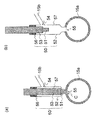
- the injection valve includes a plug, a body having a space for accommodating the plug, and a shaft for supporting and operating the plug in the space.
- the replenishment line is switchably connected to a supply source of the raw material monomer and the polymerization initiator and a supply source of the raw material monomer and the polymerization inhibitor.
- the continuous polymerization apparatus as described.
- the first and second reactors are tank reactors, and the outlet of each reactor is located at the top of each reactor, according to any one of [1] to [4] Continuous polymerization equipment.
- the continuous polymerization apparatus according to any one of [1] to [6], wherein the first and second reaction apparatuses further include temperature detection means for detecting the temperature in each reaction apparatus.
- the raw material monomer and the polymerization initiator are continuously supplied from the supply source of the raw material monomer and the polymerization initiator to the first reaction device from the supply port of the first reaction device, and the continuous polymerization is performed in the first reaction device.
- a first polymerization step in which the intermediate composition thus obtained is continuously withdrawn from the outlet of the first reactor; While the intermediate composition reaches from the outlet of the first reactor to the supply port of the second reactor through the connection line, the fluid containing at least the raw material monomer is intermediated from the replenishment line via the injection valve.
- a method for producing a polymer composition. [13] The method for producing a polymer composition according to [12], wherein the fluid containing at least the raw material monomer further contains a polymerization initiator. [14] At least the intermediate composition is continued by the cooling means of the connection line from the outlet of the first reactor through the connection line to the supply port of the second reactor.
- the temperature of the mixture at the supply port of the second reactor is 5 to 80 ° C. lower than the temperature of the intermediate composition at the discharge port of the first reactor.
- the manufacturing method of the polymer composition in any one.
- the raw material monomer and the polymerization initiator are continuously supplied from the supply source of the raw material monomer and the polymerization initiator to the first reaction device from the supply port of the first reaction device, and the continuous polymerization is performed in the first reaction device.
- a polymerization step of continuously extracting the intermediate composition thus obtained from the outlet of the first reactor While the intermediate composition reaches from the outlet of the first reactor to the supply port of the second reactor through the connection line, the fluid containing at least the raw material monomer is intermediated from the replenishment line via the injection valve.
- a method for producing a polymer composition comprising a step of continuously feeding from a mouth, passing through a second reactor, and continuously passing out from the outlet of the second reactor as a polymer composition.
- An injection valve including a plug, a body having a space for accommodating the plug, and a shaft for supporting and operating the plug in the space, An injection valve in which a gap is formed between the inner wall surface of the body and the surface of the plug when the injection valve is fully closed.
- the injection valve according to [21] which is used in a reactor for carrying out polymerization.
- a novel continuous polymerization apparatus is provided. More specifically, the continuous polymerization apparatus of the present invention is suitable to be operated by switching between a two-stage polymerization operation and a one-stage polymerization operation.
- the resin composition obtained from the coalescence composition can be produced while effectively preventing coloring.
- the manufacturing method of the polymer composition which can be implemented using such a continuous polymerization apparatus and can manufacture a polymer composition from which quality differs is also provided.
- an injection valve that can be used in such a continuous polymerization apparatus (but is not limited to such an application) is also provided.
- the continuous polymerization apparatus of the present invention includes at least two reaction apparatuses, and continuous polymerization such as continuous bulk polymerization and continuous solution polymerization can be performed in each reaction apparatus.
- the continuous polymerization apparatus of the present invention is understood as a continuous bulk polymerization apparatus when continuous bulk polymerization is performed in all reactors, and a continuous solution polymerization apparatus when continuous solution polymerization is performed in all reaction apparatuses.
- the present invention is not limited thereto, and the continuous polymerization apparatus of the present invention is such that a continuous bulk polymerization is performed in a certain reaction apparatus (for example, at least one reaction apparatus in the preceding stage), and a certain reaction apparatus (for example, at least one in the subsequent stage). In the reactor), continuous solution polymerization may be carried out.
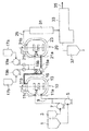
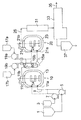
- the continuous polymerization apparatus of this embodiment includes at least a first reaction apparatus 10 and a second reaction apparatus 20.
- These reactors 10 and 20 are not particularly limited as long as they can carry out continuous polymerization such as continuous bulk polymerization and continuous solution polymerization, and are preferably used for carrying out continuous bulk polymerization.
- the reactors 10 and 20 may be, for example, tank reactors or tube reactors, and are preferably (continuous) tank reactors.
- it is preferable that the reactors 10 and 20 are completely mixed reactors. More preferably, the reactors 10 and 20 are both fully mixed (continuous) tank reactors, and more preferably used for carrying out continuous bulk polymerization.
- a completely mixed (continuous) tank reactor is used as the reactors 10 and 20 will be described with respect to the embodiments of the present invention. However, the reactor used in the present invention is limited to these. is not.
- the first reaction apparatus 10 has a supply port 11a and an extraction port 11b, and preferably a jacket 13 as temperature adjusting means for adjusting the temperature of the outer wall surface of the reaction apparatus, And a stirrer 14 for stirring the product.
- the second reaction device 20 has a supply port 21a and an extraction port 21b, and preferably a jacket surrounding the outer wall surface of the reaction device as temperature adjusting means for adjusting the temperature of the outer wall surface of the reaction device. 23 and a stirrer 24 for stirring the contents.
- the extraction ports 11b and 21b are provided so as to be located at the top of each reaction apparatus in the present embodiment, but are not limited thereto.
- supply port 11a and 21a do not limit this embodiment, generally it can be provided in the appropriate position under each reactor.
- these reaction apparatuses 10 and 20 may each include a temperature sensor T as temperature detection means for detecting the temperature in each reaction apparatus.
- the volumes of the first reactor 10 and the second reactor 20 may be the same or different. By making the volume of the first reactor 10 and the volume of the second reactor 20 different, the average residence time is effectively made different between the first reactor 10 and the second reactor 20. Can do.
- the stirrers 14 and 24 are for bringing the inside of the reactor into a substantially complete mixed state.
- These agitators may be equipped with any appropriate agitating blade, such as a MIG wing, a Max blend wing (registered trademark, manufactured by Sumitomo Heavy Industries, Ltd.), a paddle wing, a double helical ribbon wing, a full zone. Wings (registered trademark, manufactured by Shinko Environmental Solution Co., Ltd.) may be provided.
- a baffle in the reactor.
- the present embodiment is not limited to this, and may preferably have any appropriate configuration in place of the agitators 14 and 24 as long as the inside of the reaction apparatus can be substantially completely mixed.
- the stirring power is not particularly limited, but is preferably 0.5 to 30 kW / m 3 , more preferably 0.5 to 20 kW / m 3 , and even more preferably 1 to 15 kW / m 3. 3 .
- the stirring power is preferably set larger as the viscosity of the reaction system becomes higher (or as the content of the polymer in the reaction system becomes higher).
- the supply port 11a of the first reactor 10 is pumped to a raw material monomer tank (raw material monomer supply source) 1 and a polymerization initiator tank (a polymerization initiator and optionally a raw material monomer supply source) 3 respectively.
- the raw material supply line 9 is connected through 5 and 7.
- the raw material monomer and polymerization initiator supply sources are the raw material monomer tank 1 and the polymerization initiator tank 3, but the number of raw material monomer and polymerization initiator supply sources and the raw material monomer and polymerization initiator modes (For example, in the case of a mixture, the composition thereof) and the like are not particularly limited as long as the raw material monomer and the polymerization initiator can be appropriately supplied to the first reactor 10.
- the first reactor 10 is provided with another supply port 11c.
- This supply port 11c is connected to the polymerization initiator tank 3 with a pump 7 as shown by a dotted line in FIG. It may be connected via.
- the extraction port 11b of the first reactor 10 is connected to the supply port 21a of the second reactor 20 through a connection line 15a.
- the extraction port 21 b of the second reactor 20 is connected to the extraction line 25.
- the 1st reaction apparatus 10 and the 2nd reaction apparatus 20 are connected in series. It is preferable that no pump exists on the connection line 15a between the outlet 11b of the first reactor 10 and the supply port 21a of the second reactor 20.
- connection line 15a joins via the replenishment line 15b and the injection valve 50 at the junction located between the outlet 11b of the first reactor 10 and the supply port 21a of the second reactor 20.
- the replenishment line 15b is connected to a two-stage polymerization raw material monomer tank (a supply source of new raw material monomer and polymerization initiator) 17a via a pump 19a, and the first stage polymerization raw material monomer A tank (a supply source of new raw material monomer and polymerization inhibitor) 17b is connected via a pump 19b.
- the replenishment line 15b is switchably connected to the raw material monomer and polymerization initiator supply source and the raw material monomer and polymerization inhibitor supply source.
- the raw material monomer tank 17a for two-stage polymerization contains a polymerization initiator in addition to the raw material monomer, it can be understood as a supply source of a new polymerization initiator.
- the number of the supply sources and the mode of the polymerization initiator are not particularly limited as long as a new polymerization initiator can be appropriately supplied to the second reactor 20.
- the supply port 21a of the second reactor 20 may be connected to the two-stage polymerization raw material monomer tank 17a via the pump 19a through the connection line 15a by the injection valve 50, as shown by the solid line in FIG. Further, another supply port 21c is provided in the second reactor 20, and this supply port 21c may be connected to the polymerization initiator tank 17a via a pump 19a, for example, as indicated by a dotted line in FIG. Good.
- the present invention is not limited to such an embodiment, and it is sufficient that a fluid containing at least a raw material monomer can be supplied from the replenishment line 15b to the replenishment line 15a from the injection valve 50.
- a fluid containing at least a raw material monomer can be supplied from the replenishment line 15b to the replenishment line 15a from the injection valve 50.
- the raw material monomer is included, and both the polymerization initiator and the polymerization inhibitor are included.
- a non-common (common) raw material monomer tank and a pump associated therewith may be used.
- the injection valve 50 includes a plug 51, a body 52 having a space for accommodating the plug 51, and a shaft 53 for supporting and operating the plug 51 in the space.
- the shaft 53 is connected to a drive unit (not shown), and can be operated (moves up and down in the embodiment shown) while supporting the plug 51 in the body 52.
- the body 52 is formed with an inlet 54 and an outlet 55.
- the introduction port 54 communicates with the replenishment line 15b so that a fluid containing at least a raw material monomer can be introduced into the body 52 from the replenishment line 15b.
- the outflow port 55 communicates with the connection line 15a so that a fluid containing at least the raw material monomer introduced into the body 52 can be supplied to the connection line 15a.
- the body 52 has a tapered portion as shown in the figure, for example, and the plug 51 is fitted in the vicinity of the outlet 55 of the body 52 (leaving a gap C as will be described later) by operating the plug 51 through the shaft 53. It is possible.
- a seal portion 56 can seal between the body 52 and the shaft 53.
- FIG. 2A when the tip of the plug 51 is substantially flush with the inner wall surface of the connection line 15a, the injection valve 50 is assumed to be in a fully closed state. As shown in FIG.
- the injection valve 50 when the tip of the plug 51 is at a position farthest from the outlet 55, the injection valve 50 is assumed to be fully open.
- the injection valve 50 In the fully closed state shown in FIG. 2A, the injection valve 50 has a gap C between the inner wall surface of the body 52 and the surface of the plug 51, and a fluid containing at least a raw material monomer is replenished through the gap C. 15b can flow to the connection line 15a.
- the internal volume of the body 52 in other words, the volume of the internal space 57 that can be filled with the fluid of the body 52 changes between the fully closed state shown in FIG. 2 (a) and the fully open state shown in FIG. 2 (b). To do.
- the internal volume of the body 52 in the fully closed state may be, for example, 1 to 30%, preferably 1 to 20%, of the internal volume of the body 52 in the fully open state.
- a fluid containing at least the raw material monomer stays (particularly when the fluid contains a polymerization initiator). It is possible to prevent clogging of C, and by setting it to 30% or less, it is effective that the resin composition finally obtained is colored (even if this fluid contains a polymerization inhibitor). Can be prevented.
- the pumps 5, 7, 19a, and 19b are not particularly limited, but are preferably pumps that can set the flow rate from the tanks 1, 3, 17a, and 17b to a constant amount. Specifically, a multiple reciprocating pump is preferable, and a non-pulsating constant pump such as a double non-pulsating metering pump or a triple non-pulsating metering pump is more preferable.
- the supply amount (or supply flow rate, the same applies hereinafter) of the raw material monomer and the polymerization initiator to the first reactor 10 and the fluid containing at least the raw material monomer to the second reactor 20 (in this embodiment) A mixture of the raw material monomer and the polymerization initiator, or a mixture of the raw material monomer and the polymerization inhibitor) can be controlled.
- connection line 15a that connects the outlet 11b of the first reactor 10 to the supply port 21a of the second reactor 20 serves as a cooling means that can at least partially cool the connection line 15a.
- Jacket 16 surrounding part or all of the outer wall surface of 15a shown by hatching in FIG. 3
- cooler 40 replacing part of connection line 15a as shown in FIG. 4
- trace piping for passing refrigerant A connection line with a jacket is understood as a double tube.
- the first reaction apparatus 10 includes the temperature sensor T as temperature detection means for detecting the temperature in the first reaction apparatus 10, and thus the jacket 16 and the cooler 40 ( The cooling means) is such that the temperature in the connection line 15a in the vicinity of the supply port 21a of the second reactor 20 is lower than the temperature in the first reactor 10 detected by the temperature sensor T. Can be controlled.
- the cooler 40 is provided in the connection line 15a in any appropriate manner, and the line portion other than the cooler 40 of the connection line 15a is kept warm by covering it with a heat insulating material (not shown).
- a jacket surrounding the outer wall surface of the connection line 15a may be used in combination for cooling.
- Such cooling is preferably performed in a two-stage polymerization operation, but may be performed in a one-stage polymerization operation.
- connection line 15a increases the uniformity of the temperature distribution in the connection line 15a, and prevents the connection line 15a from being blocked by an intermediate composition (described later) flowing in the connection line 15a. It is preferable to provide a mixing means in that it can be suppressed.
- the mixing means is preferably provided in the cooling portion of the connection line 15a in terms of increasing the cooling efficiency. Examples of the mixing means include a static mixer and a dynamic mixer. Among them, a static mixer is preferable.
- the static mixer is a mixer that does not require a drive unit, and is provided in the connection line 15a in any appropriate manner. For example, in FIGS.
- a static mixer may be inserted at an appropriate position inside the connection line 15a, or a part or all of the connection line 15a may be replaced with a static mixer that forms the line. Also good.
- the static mixer may be inserted in an appropriate position inside the line portion other than the cooler 40 of the connection line 15a, or a part or all of the line portion other than the cooler 40 of the connection line 15a. May be replaced with a static mixer forming a line.
- the static mixer include “Sulzer Mixer” manufactured by Sulzer Chemtech Ltd. For example, SMX type, SMI type, SMV type, SMF type, SMXL type, etc. are used. Can be done.
- the cooler 40 may be provided with both a cooling means and a mixing means.
- Examples of the cooler 40 having both a cooling unit and a mixing unit include a cooler having a dynamic mixing function and a cooler having a static mixing function.
- Examples of the cooler having a dynamic mixing function include a screw mixer that can cool a cylinder.
- a static mixer built-in type heat exchanger etc. are mentioned, for example.
- As the heat exchanger with a built-in static mixer an SMR-type sulzer mixer manufactured by Sruzer Chemtech Co., Ltd. is preferably used because it has a large heat transfer area and a high cooling capacity can be obtained.
- a static mixer built-in heat exchanger is used as the cooler 40, a part or all of the connection line 15a may be replaced with a static mixer built-in heat exchanger that forms a line.
- the temperature of the outer wall surface of the reaction apparatus set for the jackets (temperature adjusting means) 13 and 23 and the temperature in the reaction apparatus detected by the temperature sensor (temperature detection means) T are the first
- the raw material monomers and The supply amount of the polymerization initiator to the first reactor 10 can be adjusted by adjusting the operation of the pumps 5 and 7, or the temperature of the outer wall surface of the reactor set for the jackets 13 and 23 can be adjusted.
- a fluid containing at least a raw material monomer in this embodiment, a mixture of a raw material monomer and a polymerization initiator, or a mixture of a raw material monomer and a polymerization inhibitor
- Additional feed to the second reactor 20 can be adjusted the operation of the pump 19a and 19b.
- the connection line is used so that the polymerization temperature in the second reactor 20 is not excessively high while achieving a desired polymerization rate in the second reactor 20.
- the temperature in the connection line 15a in the vicinity of the supply port 21a of the second reactor 20 is changed to the temperature.
- the temperature can be lower than the temperature in the first reactor 10 detected by the sensor (temperature detecting means) T.
- the first reaction in which the temperature in the connection line 15a in the vicinity of the supply port 21a of the second reaction device 20 is detected by the temperature sensor (temperature detection means) T is adjusted. Can be such that the temperature lower than the temperature in the location 10.
- the temperature in the connection line 15a is actually measured by temperature detection means for detecting the temperature in the connection line 15a in the vicinity of the supply port 21a of the second reactor 20 and in some other places.
- the polymerization reaction of an intermediate composition (described later) extracted from the extraction port 11b may be caused by factors such as consumption of the supplied polymerization initiator.
- 15a does not proceed, that is, the polymerization reaction heat may not be generated in the connection line 15a.
- the temperature in the connection line 15a in the vicinity of the outlet 11b of the first reactor 10 is The temperature in the first reaction apparatus 10 detected by the temperature sensor (temperature detection means) T may be considered as substantially the same temperature.
- the temperature of the jacket 16 covering the connection line 15a or the temperature of the cooler 40 replacing a part of the connection line 15a is set to a temperature lower than the temperature in the first reactor 10.
- the temperature in the connection line 15 a in the vicinity of the supply port 21 a of the second reactor 20 is considered to be lower than the temperature in the first reactor 10.
- surroundings is provided in line parts other than the cooler 40 of the connection line 15a, you may adjust the temperature in the connection line 15a by using this jacket together.
- the jackets 13 and 23 cover substantially the entirety of each of the reaction devices 10 and 20, and the reaction is performed by introducing a heat medium such as steam, hot water, or an organic heat medium from a heat medium supply path (not shown).
- the apparatuses 10 and 20 are appropriately heated or kept warm.
- the temperatures of the jackets 13 and 23 can be appropriately adjusted depending on the temperature or pressure of the supplied heat medium.
- the heat medium introduced into the jackets 13 and 23 is removed from the heat medium discharge path (not shown).
- the temperature and pressure of the jackets 13 and 23 are detected by a sensor such as a temperature sensor (not shown) provided on the heat medium discharge path.
- the location of the sensor such as the temperature sensor is not particularly limited, and may be on the heat medium supply path or in the jackets 13 and 23, for example.
- connection line 15 a may have the same configuration as the jackets 13 and 23.
- connection line 15a may be a double tube, and the inner space of the inner tube serves as a flow path for an intermediate composition (described later), and the inner tube and The space between the outer pipes is a heat medium flow path (jacket 16).
- the polymerization reaction in the reaction apparatuses 10 and 20 (the polymerization reaction in the reaction apparatus 20 is the same when the operation is performed in a two-stage polymerization operation) from the viewpoint of maintaining the quality of the polymer to be formed constant.
- the temperature adjusting means (jackets 13 and 23) is controlled to a preset constant temperature so that the internal temperatures of the reactors 10 and 20 can be kept substantially constant.
- the set temperature of the temperature adjusting means (jackets 13 and 23) is transmitted to a control means to be described later, and monomer supply means (pumps 5, 19a, 19b), initiator supply means (pumps 7, 19a) and stop agent supply means. This is data for determining whether or not the supply flow rate needs to be controlled by the (pump 19b).
- the set temperature of the temperature adjusting means (jackets 13 and 23) can be adjusted by controlling the temperature or pressure of the heating medium.
- control means examples include a control unit (not shown) including a CPU, a ROM, a RAM, and the like.
- the ROM of the control unit is a device for storing a program for controlling the pumps 5, 7, 19a, 19b, etc.
- the RAM of the control unit is detected by the temperature sensor T in order to execute the program.
- a device that temporarily stores temperature data in the reactors 10 and 20, data on the set temperatures of the jackets 13 and 23, and data on the set temperature of the jacket 16 or the cooler 40 in the connection line 15a if present. is there.
- the CPU of the control unit executes the program stored in the ROM based on the temperature data in the reaction devices 10 and 20 and the set temperature data of the jackets 13 and 23 stored in the RAM, and performs a reaction.
- the supply flow rate of the raw material monomer, the polymerization initiator and / or the polymerization inhibitor into the apparatuses 10 and 20 is changed to the monomer supply means (pumps 5, 19a, 19b), the initiator supply means (pumps 7, 19a) and / or the stop. It is controlled by the agent supply means (pump 19b).
- the CPU of the control unit stores the temperature data in the reactors 10 and 20 stored in the RAM and the jacket of the connection line 15a. 16 or the set temperature data of the cooler 40 and, if actually measured, the temperature in the connection line 15a in the vicinity of the supply port 21a of the second reactor 20 and in other locations, the ROM A stored program (which may be a part of the program or a program different from the program) may be executed to adjust the set temperature of the jacket 16 or the cooler 40 of the connection line 15a.
- control means control unit
- the valve V between the replenishment line 15b and the pump 19b is closed, the valve V between the replenishment line 15b and the pump 19a is opened, and the injection valve 50 is controlled to be fully opened.
- the valve V between the replenishment line 15b and the pump 19a is closed, the valve V between the replenishment line 15b and the pump 19b is opened, and the injection valve 50 is controlled to be fully closed.
- the CPU executes the program in the ROM.
- the pump 7 is controlled so as to decrease the supply flow rate of the polymerization initiator into the reactor 10.
- the raw material monomer and the polymerization initiator are supplied to the reaction apparatus 20 by the pump 19a, and the temperature in the reaction apparatus 20 detected by the temperature sensor T is detected by the temperature sensor T.
- the program in the ROM is executed by the CPU, thereby controlling the pump 19a so as to reduce the supply flow rates of the raw material monomer and the polymerization initiator into the reaction apparatus 20, for example.
- the heat of polymerization generated in the reactor 10 and / or 20 can be reduced, and as a result, the temperature in the reactor 10 and / or 20 can be lowered.
- the two-stage polymerization operation and the first-stage polymerization operation when the temperature of the reaction apparatus 10 is lower than the set temperature of the jacket 13, by executing the program in the ROM by the CPU, for example, into the reaction apparatus 10
- the pump 7 is controlled so as to increase the supply flow rate of the polymerization initiator.
- the raw material monomer and the polymerization initiator are supplied to the reaction device 20 by the pump 19a and the polymerization is being performed.
- the CPU stores the contents in the ROM.
- the pump 19a is controlled so as to increase the supply flow rates of the raw material monomer and the polymerization initiator into the reaction apparatus 20.
- the heat of polymerization generated in the reactor 10 and / or 20 can be increased, and as a result, the temperature in the reactor 10 and / or 20 can be increased.
- control examples include the following control. That is, in the two-stage polymerization operation and the first-stage polymerization operation, when the temperature in the reactor 10 detected by the temperature sensor T exceeds the set temperature of the jacket 13 that is a temperature adjusting means, the pump 5 is controlled to control the raw material. By increasing the monomer supply flow rate, the relative supply flow rate of the polymerization initiator into the reactor 10 is decreased. Also by such control, the temperature in the reactor 10 can be lowered.
- the ratio between the supply flow rate of the raw material monomer and the supply flow rate of the polymerization initiator may be appropriately set according to the type of polymer to be produced, the type of polymerization initiator to be used, and the like. Further, the supply flow rate of the raw material monomer and the extent to increase or decrease the supply flow rate of the polymerization initiator are appropriately set according to the type of polymer to be produced, the type of polymerization initiator to be used, etc. .
- the initiator supply means when what is supplied into the reactors 10 and 20 by the initiator supply means is not a polymerization initiator alone but a raw material monomer containing a polymerization initiator, the supply flow rate of the polymerization initiator is the polymerization start It is necessary to control in consideration of the content ratio of the polymerization initiator in the raw material monomer including the agent.
- the jacket 16 or the cooler 40 that can be provided as a cooling means in the connection line 15a
- the following control is exemplified.
- the temperature in the connection line 15a in the vicinity of the supply port 21a of the second reactor 20 is equal to or higher than the temperature in the first reactor 10 detected by the temperature sensor T
- the temperature in the connection line 15a in the vicinity of the supply port 21a of the second reactor 20 is lower than the temperature in the first reactor 10, preferably 5 Control related equipment (not shown) of the jacket 16 or the cooler 40 so as to adjust the set temperature of the jacket 16 or the cooler 40 of the connecting line 15a to a lower temperature so that the temperature is lower by -80 ° C.
- the set temperature of the jacket 16 of the connection line 15a is not particularly limited, but is generally adjustable by controlling the flow rate and / or temperature of the heat medium flowing through the jacket 16.
- the set temperature of the cooler 40 in the connection line 15a is not particularly limited, but when a static mixer built-in heat exchanger is used as the cooler 40, the flow rate of the heat medium generally flowing through the static mixer built-in heat exchanger And / or can be adjusted by controlling the temperature.
- the following control can be performed.
- the first reactor in which the temperature in the second reactor 20 detected by the temperature sensor T in the second reactor 20 is detected by the temperature sensor T in the first reactor 10 When the temperature is equal to or higher than the temperature in 10, the CPU executes the program in the ROM so that the temperature in the connection line 15a in the vicinity of the supply port 21a of the second reactor 20 is within the first reactor 10.
- Setting of the jacket 16 of the connection line 15a or the cooler 40 (and the jacket when the cooler 40 and the jacket are used together) as appropriate so that the temperature is lower than the temperature of this, preferably 5 to 80 ° C.
- a preheater 31 and a devolatilizing extruder 33 can be disposed downstream of the extraction line 25.
- a pressure regulating valve (not shown) may be provided between the preheater 31 and the devolatilizing extruder 33. The extrudate after devolatilization is taken out from the take-out line 35.
- the devolatilizing extruder 33 may be a screw type single-screw or multi-screw devolatilizing extruder.
- a recovery tank 37 for storing raw material monomers separated and recovered from volatile components (mainly including unreacted raw material monomers) separated by the devolatilizing extruder 33.
- the production method of the polymer composition of the present embodiment is carried out using the above-described continuous polymerization apparatus so as to be switchable between a two-stage polymerization operation and a one-stage polymerization operation.
- a methacrylic ester monomer is continuously polymerized, in other words, a case where a methacrylic ester polymer is produced will be described, but the present invention is not limited thereto.
- raw material monomers a polymerization initiator and a polymerization inhibitor are prepared.
- a methacrylic acid ester monomer is used as the raw material monomer.
- methacrylic acid ester monomers include: ⁇ Alkyl methacrylate (alkyl group having 1 to 4 carbon atoms) alone or ⁇ Methyl methacrylate (alkyl group having 1 to 4 carbon atoms) 80% by weight or more, copolymerizable with this And a mixture with other vinyl monomers of 20% by weight or less.
- alkyl methacrylate examples include, for example, methyl methacrylate, ethyl methacrylate, n-propyl methacrylate, isopropyl methacrylate, n-butyl methacrylate, t-methacrylic acid t- Examples thereof include butyl, sec-butyl methacrylate, and isobutyl methacrylate. Among them, methyl methacrylate is preferable.
- the alkyl methacrylates exemplified above may be used alone or in combination of two or more.
- Examples of the copolymerizable vinyl monomer include a monofunctional monomer having one radical polymerizable double bond and a polyfunctional monomer having two or more radical polymerizable double bonds. It is done.
- examples of the monofunctional monomer having one radical-polymerizable double bond include methacrylic acid esters such as benzyl methacrylate and 2-ethylhexyl methacrylate (provided that the alkyl methacrylate (alkyl Acrylic esters such as methyl acrylate, ethyl acrylate, propyl acrylate, butyl acrylate, 2-ethylhexyl acrylate; acrylic acid, methacrylic acid, Unsaturated carboxylic acids such as maleic acid, itaconic acid, maleic anhydride, itaconic anhydride or their anhydrides; 2-hydroxyethyl acrylate, 2-hydroxypropyl acrylate, monoglycerol acrylate, 2-hydroxy methacrylate Ethyl, 2-
- Epoxy group-containing monomers styrene monomers such as styrene and ⁇ -methylstyrene.
- the polyfunctional monomer having two or more double bonds capable of radical polymerization include unsaturated carboxylic acid diesters of glycols such as ethylene glycol dimethacrylate and butanediol dimethacrylate; allyl acrylate, allyl methacrylate, Alkenyl esters of unsaturated carboxylic acids such as allyl cinnamate; polyalkenyl esters of polybasic acids such as diallyl phthalate, diallyl maleate, triallyl cyanurate, triallyl isocyanurate; multivalents such as trimethylolpropane triacrylate Unsaturated carboxylic acid ester of alcohol; divinylbenzene.
- the above exemplified copolymerizable vinyl monomers may be used singly or in combination of two or more.
- a radical initiator is used as the polymerization initiator.
- the radical initiator include azobisisobutyronitrile, azobisdimethylvaleronitrile, azobiscyclohexanenitrile, 1,1′-azobis (1-acetoxy-1-phenylethane), dimethyl 2,2′-azo.
- Azo compounds such as bisisobutyrate and 4,4′-azobis-4-cyanovaleric acid; benzoyl peroxide, lauroyl peroxide, acetyl peroxide, caprylyl peroxide, 2,4-dichlorobenzoyl peroxide, isobutyl peroxide Oxide, acetylcyclohexylsulfonyl peroxide, t-butylperoxypivalate, t-butylperoxyneodecanoate, t-butylperoxyneoheptanoate, t-butylperoxy-2-ethylhexanoate, 1 , 1-Di ( -Butylperoxy) cyclohexane, 1,1-di (t-butylperoxy) -3,3,5-trimethylcyclohexane, 1,1-di (t-hexylperoxy) -3,3,5-trimethylcyclohexane ,
- the polymerization initiator is selected according to the type of polymer to be produced and the raw material monomer to be used.
- the polymerization initiator (radical initiator) has a half-life of the polymerization initiator at the polymerization temperature of ⁇ (seconds) and an average residence time in the reaction apparatus of ⁇ ( As the second), ⁇ / ⁇ ( ⁇ ) is, for example, 0.1 or less, preferably 0.02 or less, more preferably 0.01 or less. If the value of ⁇ / ⁇ is equal to or less than this value, the polymerization initiator is sufficiently decomposed in the reaction apparatus (and thus radical generation), and the polymerization reaction can be effectively started.
- the polymerization initiator is sufficiently decomposed in the first reactor 10, it can be effectively reduced that the polymerization initiator is decomposed in the connection line 15 a to start the polymerization. It can be effectively avoided that the viscosity of the composition increases while it passes through the connection line 15a, and that the connection line 15a is blocked by the intermediate composition.
- the supply amount of the polymerization initiator is not particularly limited, but is usually 0.001 to 1% by weight with respect to the raw material monomer (raw material monomer finally supplied to the reactor 10). It is.
- the polymerization initiator can be supplied separately to the first reaction apparatus 10 and the second reaction apparatus 20. .
- the total supply of the polymerization initiator supplied to the reactor 10 and the reactor 20 The amount may be within the above range with respect to the total amount of the raw material monomer finally supplied to the reactor 10 and the raw material monomer newly supplied to the reactor 20.
- phenols such as hydroquinone, 2,4-dimethyl-6-tert-butylphenol, and hydroquinone monomethyl ether
- amines such as phenothiazine and diphenylamine
- copper such as copper dibutyldithiocarbamate Salt
- manganese salt such as manganese acetate
- nitro compound nitroso compound and the like.
- the polymerization inhibitor to be used is appropriately selected according to the polymer to be produced and the monomer used as the raw material.
- the supply amount of the polymerization inhibitor is not particularly limited, but the content of the polymerization inhibitor in the fluid containing the raw material monomer (fluid supplied to the injection valve 50) is 0.0002 to 0.2% by weight. Can be set to By setting the content ratio to be equal to or less than the above upper limit value, the ratio of the polymerization inhibitor supplied to the reaction apparatus 20 does not become too high, and the resin composition finally obtained can be effectively prevented from being colored. In addition, by setting the supply amount to be equal to or higher than the lower limit, it is possible to effectively suppress the raw material monomer from being polymerized and clogging in the gap C of the injection valve 50.
- any appropriate other components such as chain transfer agents, release agents, rubbery polymers such as butadiene and styrene butadiene rubber (SBR), heat Stabilizers and UV absorbers may be used.
- Chain transfer agents are used to adjust the molecular weight of the polymer produced.
- a mold release agent is used in order to improve the moldability of the resin composition obtained from a polymer composition.
- a heat stabilizer is used in order to suppress thermal decomposition of the produced polymer.
- An ultraviolet absorber is used in order to suppress deterioration by the ultraviolet-ray of the polymer to produce
- the chain transfer agent may be either a monofunctional or polyfunctional chain transfer agent. Specifically, for example, n-propyl mercaptan, isopropyl mercaptan, n-butyl mercaptan, t-butyl mercaptan, n-hexyl mercaptan, n-octyl mercaptan, 2-ethylhexyl mercaptan, n-dodecyl mercaptan, t-dodecyl mercaptan, etc.
- Alkyl mercaptans such as phenyl mercaptan and thiocresol; mercaptans having 18 or less carbon atoms such as ethylene thioglycol; ethylene glycol, neopentyl glycol, trimethylolpropane, pentaerythritol, dipentaerythritol, tripentaerythritol, Polyhydric alcohols such as sorbitol; hydroxyl group esterified with thioglycolic acid or 3-mercaptopropionic acid, 1,4- Tetrahydronaphthalene, 1,4,5,8-tetrahydronaphthalene, beta-terpinene, terpinolene, 1,4-cyclohexadiene, and the like hydrogen sulfide. These may be used alone or in combination of two or more.
- the supply amount of the chain transfer agent is not particularly limited because it varies depending on the type of the chain transfer agent to be used.
- the raw material monomer (finally the reactor) Is preferably from 0.01 to 3% by weight, more preferably from 0.05 to 1% by weight, based on the raw material monomer supplied to 10 or 20.
- the release agent is not particularly limited, and examples thereof include higher fatty acid esters, higher aliphatic alcohols, higher fatty acids, higher fatty acid amides, and higher fatty acid metal salts. In addition, only 1 type may be sufficient as a mold release agent, and 2 or more types may be sufficient as it.
- higher fatty acid esters include, for example, methyl laurate, ethyl laurate, propyl laurate, butyl laurate, octyl laurate, methyl palmitate, ethyl palmitate, propyl palmitate, butyl palmitate, and palmitate.
- methyl stearate, ethyl stearate, butyl stearate, octyl stearate, stearic acid monoglyceride, stearic acid diglyceride, stearic acid triglyceride and the like are preferable.
- the higher aliphatic alcohol include saturated aliphatic alcohols such as lauryl alcohol, palmityl alcohol, stearyl alcohol, isostearyl alcohol, behenyl alcohol, myristyl alcohol, cetyl alcohol; oleyl alcohol, linolyl alcohol, and the like.
- saturated aliphatic alcohols such as lauryl alcohol, palmityl alcohol, stearyl alcohol, isostearyl alcohol, behenyl alcohol, myristyl alcohol, cetyl alcohol; oleyl alcohol, linolyl alcohol, and the like.
- unsaturated fatty alcohols Of these, stearyl alcohol is preferred.
- higher fatty acids include, for example, caproic acid, caprylic acid, capric acid, lauric acid, myristic acid, palmitic acid, stearic acid, arachidic acid, behenic acid, lignoceric acid, and 12-hydroxyoctadecanoic acid.
- Fatty acids unsaturated fatty acids such as palmitoleic acid, oleic acid, linoleic acid, linolenic acid, cetreic acid, erucic acid, ricinoleic acid and the like.
- the higher fatty acid amide include saturated fatty acid amides such as lauric acid amide, palmitic acid amide, stearic acid amide, and behenic acid amide; unsaturated fatty acid amides such as oleic acid amide, linoleic acid amide, and erucic acid amide.
- higher fatty acid metal salts include sodium salts, potassium salts, calcium salts and barium salts of the higher fatty acids described above.
- the amount of the release agent used is preferably adjusted to be 0.01 to 1.0 part by weight with respect to 100 parts by weight of the polymer contained in the obtained polymer composition. It is more preferable to adjust so that it may become 50 weight part.
- the heat stabilizer is not particularly limited, and examples thereof include phosphorus heat stabilizers and organic disulfide compounds. Of these, organic disulfide compounds are preferred. In addition, only 1 type may be sufficient as a heat stabilizer, and 2 or more types may be sufficient as it.
- Examples of the phosphorus-based heat stabilizer include tris (2,4-di-t-butylphenyl) phosphite, 2-[[2,4,8,10-tetrakis (1,1-dimethylethyl) dibenzo [d.
- organic disulfide compounds include dimethyl disulfide, diethyl disulfide, di-n-propyl disulfide, di-n-butyl disulfide, di-sec-butyl disulfide, di-tert-butyl disulfide, di-tert-amyl disulfide, dicyclohexyl.
- examples thereof include disulfide, di-tert-octyl disulfide, di-n-dodecyl disulfide, di-tert-dodecyl disulfide and the like.
- di-tert-alkyl disulfide is preferable, and di-tert-dodecyl disulfide is more preferable.
- the amount of the heat stabilizer used is preferably 1 to 2000 ppm by weight based on the polymer contained in the resulting polymer composition.
- the molding temperature is set high for the purpose of increasing molding efficiency. In such a case, it is more effective to add a heat stabilizer.
- UV absorbers examples include benzophenone UV absorbers, cyanoacrylate UV absorbers, benzotriazole UV absorbers, malonic ester UV absorbers, and oxalanilide UV absorbers.
- An ultraviolet absorber may be used independently and may be used in combination of 2 or more type. Among these, benzotriazole type ultraviolet absorbers, malonic acid ester type ultraviolet absorbers, and oxalanilide type ultraviolet absorbers are preferable.
- benzophenone-based UV absorber examples include 2,4-dihydroxybenzophenone, 2-hydroxy-4-methoxybenzophenone, 2-hydroxy-4-methoxybenzophenone-5-sulfonic acid, 2-hydroxy-4-octyloxybenzophenone, Examples include 4-dodecyloxy-2-hydroxybenzophenone, 4-benzyloxy-2-hydroxybenzophenone, 2,2′-dihydroxy-4,4′-dimethoxybenzophenone.
- cyanoacrylate ultraviolet absorber examples include ethyl 2-cyano-3,3-diphenylacrylate, 2-ethylhexyl 2-cyano-3,3-diphenylacrylate, and the like.
- benzotriazole ultraviolet absorber examples include 2- (2-hydroxy-5-methylphenyl) -2H-benzotriazole and 5-chloro-2- (3,5-di-t-butyl-2-hydroxyphenyl). ) -2H-benzotriazole, 2- (3-t-butyl-2-hydroxy-5-methylphenyl) -5-chloro-2H-benzotriazole, 2- (3,5-di-t-pentyl-2- Hydroxyphenyl) -2H-benzotriazole, 2- (3,5-di-tert-butyl-2-hydroxyphenyl) -2H-benzotriazole, 2- (2H-benzotriazol-2-yl) -4-methyl- 6- (3,4,5,6-tetrahydrophthalimidylmethyl) phenol, 2- (2-hydroxy-5-t-octylphenyl) -2H-benzo Riazor, and the like.
- 2- (1-arylalkylidene) malonic acid esters are usually used, and examples thereof include 2- (paramethoxybenzylidene) malonic acid dimethyl.
- 2-alkoxy-2'-alkyloxalanilides are usually used, and examples thereof include 2-ethoxy-2'-ethyloxalanilide.
- the amount of the ultraviolet absorber used is preferably 5 to 1000 ppm by weight with respect to the polymer contained in the obtained polymer composition.
- the above raw material monomers (one type or a mixture of two or more types) are appropriately mixed (optionally together with other components such as a chain transfer agent).
- the polymerization initiator as described above is appropriately mixed with the raw material monomer (and optionally other components such as a chain transfer agent) as necessary.
- the polymerization initiator tank 3 may store the polymerization initiator alone or in the form of a mixture of the raw material monomer and the polymerization initiator (which may further include other components such as a chain transfer agent in some cases). May be.
- the two-stage polymerization raw material monomer tank 17a a mixture of the raw material monomer and the polymerization initiator as described above is appropriately mixed (optionally together with other components such as a chain transfer agent).
- the two-stage polymerization raw material monomer tank 17a only needs to store a fluid containing at least the raw material monomer. However, in order to promote continuous polymerization in the second reaction tank 20, such a fluid is used in the present embodiment. It is preferable to contain a raw material monomer and a polymerization initiator as described above.
- the supply port 21c is connected to the two-stage polymerization raw material monomer tank 17a via the pump 19a, if the raw material monomer is stored in the form of a mixture of the raw material monomer and the polymerization initiator as in this embodiment, the polymerization is performed. Since the initiator is premixed with a part of the raw material monomer, the possibility that the polymerization reaction locally proceeds in the reactor 20 (for example, when the polymerization initiator is supplied to the reactor 20 alone) is eliminated. Can be done.
- Second polymerization step From the raw material monomer tank 1 and the polymerization initiator tank 3 which are supply sources of the raw material monomer and the polymerization initiator, the raw material monomer and the polymerization initiator are continuously supplied to the first reactor 10 from the supply port 11a.
- Supply Specifically, the raw material monomer is supplied from the raw material monomer tank 1 by the pump 5 and the polymerization initiator tank 3 is supplied with a polymerization initiator (preferably a mixture of the raw material monomer and the polymerization initiator, simply referred to as a polymerization initiator in this specification).
- a polymerization initiator preferably a mixture of the raw material monomer and the polymerization initiator, simply referred to as a polymerization initiator in this specification.
- the polymerization initiator may be supplied from the polymerization initiator tank 3 to the first reactor 10 through the supply port 11c as shown by the dotted line in FIG.
- the supply flow rate A of the raw material monomer from the raw material monomer tank 1 Kg / h
- a feed flow rate B kg / h
- the ratio A: B to h) is preferably adjusted to be in the range of 80:20 to 98: 2.
- the temperature of the raw material monomer and the polymerization initiator supplied to the first reaction apparatus 10 is not particularly limited, but it causes the heat balance in the reaction apparatus to be lost and the polymerization temperature to fluctuate. For this reason, it is preferable to adjust the temperature appropriately before being supplied to the reaction apparatus 10 by a heater / cooler (not shown).
- the raw material monomer and the polymerization initiator supplied to the first reactor 10 as described above are subjected to continuous polymerization, in this embodiment, continuous bulk polymerization (in other words, polymerization without a solvent). .
- the first polymerization step only needs to allow the polymerization reaction to proceed halfway, and the intermediate composition is continuously extracted from the extraction port 11b of the first reactor 10.
- the continuous polymerization can be performed in a state where the reaction apparatus is filled with the reaction mixture and substantially no gas phase is present (hereinafter referred to as “full liquid state”).
- This is particularly suitable for continuous bulk polymerization. Due to this full liquid state, a problem such that the gel adheres to the inner wall surface of the reactor and grows, and a problem that the quality of the finally obtained polymer composition is deteriorated when this gel is mixed into the reaction mixture. Can be prevented in advance. Furthermore, this full liquid state can effectively use the entire volume of the reaction apparatus in the reaction space, and thus high production efficiency can be obtained.
- the full liquid state is simple by simply supplying and withdrawing the first reactor 10 continuously by positioning the outlet 11b of the first reactor 10 at the top of the reactor as in this embodiment. Can be realized.
- the position of the outlet at the top of the reactor is particularly suitable for continuous polymerization of methacrylic ester monomers.
- continuous polymerization can be carried out in an adiabatic state (a state in which there is substantially no heat in and out from the outside of the reactor).
- adiabatic state a state in which there is substantially no heat in and out from the outside of the reactor. This is particularly suitable for continuous bulk polymerization. Due to this heat insulation state, there is a problem that the gel adheres to and grows on the inner wall surface of the reactor, and a problem that the quality of the finally obtained polymer composition is deteriorated when this gel is mixed into the reaction mixture. Occurrence can be prevented in advance. Furthermore, this adiabatic state can stabilize the polymerization reaction and can provide self-controllability for suppressing the runaway reaction.
- the adiabatic state can be realized by making the temperature inside the first reactor 10 and the temperature of the outer wall surface substantially equal. Specifically, the temperature of the outer wall surface of the first reactor 10 set for the jacket (temperature adjusting means) 13 and the temperature sensor (temperature detecting means) using the above-described control means (not shown). ) Adjusting the operation of the pumps 5 and 7 for the supply amounts of the raw material monomer and the polymerization initiator to the first reactor 10 so that the temperature in the first reactor 10 detected by T matches. Can be realized. If the temperature of the outer wall surface of the reaction apparatus is set too high as compared with the temperature in the reaction apparatus, excess heat is applied to the reaction apparatus, which is not preferable. It is preferable that the temperature difference between the inside of the reaction apparatus and the outer wall surface of the reaction apparatus is as small as possible.
- the polymerization heat and heat of stirring generated in the first reactor 10 are usually carried away when the intermediate composition is extracted from the first reactor 10.
- the amount of heat that the intermediate composition takes away is determined by the flow rate of the intermediate composition, the specific heat, and the temperature of the polymerization reaction.
- the temperature of continuous polymerization in the first polymerization step is understood as the temperature in the first reactor 10 (detected by the temperature sensor T).
- the first polymerization step is performed, for example, at a temperature within the range of 120 to 180 ° C., preferably at a temperature within the range of 130 to 175 ° C.
- the temperature in the reactor can vary depending on various conditions until a steady state is reached.
- the pressure of continuous polymerization in the first polymerization step is understood as the pressure in the first reactor 10.
- This pressure is set to a pressure equal to or higher than the vapor pressure of the raw material monomer at the temperature in the reaction device so that no gas of the raw material monomer is generated in the reaction device, and is usually about 1.0 to 2.0 MPa as a gauge pressure. .
- the time given for continuous polymerization in the first polymerization step is understood as the average residence time of the first reactor 10.
- the average residence time in the first reactor 10 can be set according to the production efficiency of the polymer in the intermediate composition, and is not particularly limited, but is, for example, 15 minutes to 6 hours.
- the average residence time in the first reaction apparatus 10 can be adjusted by changing the supply amount (supply flow rate) of raw material monomers and the like to the first reaction apparatus 10 using the pumps 5 and 7, but the first reaction Since it largely depends on the volume of the apparatus 10, it is important how to design the volume of the first reactor 10 and the volume of the second reactor 20 as described later.
- the intermediate composition is continuously extracted from the extraction port 11 b of the first reactor 10.
- the obtained intermediate composition contains the produced polymer and unreacted raw material monomer, and may further contain an unreacted polymerization initiator, a polymerization initiator decomposition product, and the like.
- the polymerization rate in the intermediate composition is not limited to this embodiment, but is, for example, 5 to 80% by weight.
- the polymerization rate in the intermediate composition generally corresponds to the polymer content in the intermediate composition.
- Raw Material Monomer Supply Step After the intermediate composition obtained as described above is extracted from the extraction port 11b of the first reactor 10, it is supplied from the supply port 21a to the second reactor 20 through the connection line 15a. Continuously supplied.
- a fluid containing at least the raw material monomer is continuously supplied from the two-stage polymerization raw material monomer tank 17a, which is a supply source of the fluid containing at least the raw material monomer, to the connection line 15a.
- the fluid containing at least the raw material monomer (in this embodiment, the raw material monomer and the polymerization initiator) from the two-stage polymerization raw material monomer tank 17a is pumped through the replenishment line 15b and the injection valve 50 by the connection line 15a.
- a new raw material monomer (and a new polymerization initiator in this embodiment) is added to the intermediate composition.
- the injection valve 50 is in the fully open state described above with reference to FIG.
- the temperature of the fluid containing at least the raw material monomer supplied from the two-stage polymerization raw material monomer tank 17a to the connection line 15a is not particularly limited, but the polymerization temperature is changed by breaking the heat balance in the reactor. Therefore, it is preferable to adjust the temperature appropriately before being supplied to the connection line 15a by a heating / cooling device (not shown).
- a mixture of the raw material monomer and the polymerization initiator is prepared and supplied to the polymerization initiator tank 3 and the raw material monomer tank 17a for two-stage polymerization.
- the ratio a: (B 1 + B 2 ) is 80: 20-98: 2's range, and the ratio B 1: B 2 is from 10: 90-90: With a range of 10 It is preferable to adjust to.
- the fluid containing at least the raw material monomer from the outlet 11b of the first reactor 10 through the connection line 15a to the supply port 21a of the second reactor 20 as described above. Is supplied to the intermediate composition through the injection valve 50 from the replenishment line 15b.
- connection line 15a includes the jacket 16 or the cooler 40 as a cooling means
- the intermediate composition extracted from the extraction port 11b of the first reactor 10 is connected to the connection line 15a.
- the second reactor 20 is continuously supplied to the second reactor 20 through the supply port 21a alone or together with the fluid containing at least the raw material monomer supplied from the replenishment line 15b via the injection valve 50, or the jacket 16 or It can be continuously cooled by the cooler 40.
- connection line 15a Although not essential to the present invention, it is preferable to provide a mixing means in the connection line 15a.
- the mixing means By providing the mixing means, the intermediate composition (or the mixture of the intermediate composition and the fluid containing at least the raw material monomer) flowing in the connection line 15a is uniformly mixed, and the temperature distribution is likely to be uniform, and the intermediate composition Blockage of the connection line 15a due to (or the above mixture) can be suppressed.
- a static mixer or a dynamic mixer may be provided in the connection line 15a, or the cooler 40 having both the mixing means and the cooling means may be provided in the connection line 15a.
- the degree of cooling can vary depending on, for example, the difference between the temperature in the first reactor 10 and the temperature in the second reactor 20 as in the above preferred control example. Although it adjusts according to desired polymerization temperature and polymerization rate, specifically, the temperature of the mixture in the supply port 21a of the 2nd reactor 20 is the intermediate composition in the extraction port 11b of the 1st reactor 10. For example, it can be carried out so as to be 5 to 80 ° C. lower than this temperature.
- polymerization process is implemented in series after a 1st superposition
- the mixture of the intermediate composition extracted from the extraction port 11b of the first reactor 10 and the fluid containing at least the raw material monomer supplied from the replenishment line 15b via the injection valve 50 is connected. It is continuously supplied from the supply port 21a to the second reactor 20 from the line 15a. This mixture is further subjected to continuous polymerization in the second reactor 20, and in this embodiment, continuous bulk polymerization.
- the polymerization reaction is advanced to a desired polymerization rate, and the polymer composition (or polymerization syrup) is continuously extracted from the extraction port 21b of the second reactor 20.
- the second polymerization step will be described mainly with respect to differences from the first polymerization step, and the same description as the first polymerization step will be applied unless otherwise specified.
- a part of the fluid preferably a mixture of the raw material monomer and the polymerization initiator
- a part of the fluid containing at least the raw material monomer supplied from the two-stage polymerization raw material monomer tank 17a by the pump 19a is used for the second step.
- the temperature of the fluid containing at least the raw material monomer supplied from the polymerization initiator tank 17a to the second reactor 20 through another supply port 21c is not particularly limited, but the heat balance in the reactor is broken. Therefore, it is preferable to adjust the temperature before being supplied to the reaction apparatus 20 by a heating / cooling device (not shown) as appropriate.
- the intermediate composition extracted from the first reactor using the jacket 16 or the cooler 40 which is preferably provided as a cooling means in the connection line 15a, or such an intermediate composition.
- the mixture of the fluid containing at least the raw material monomer supplied from the replenishment line is cooled before being supplied to the second reactor. Achieving a high polymerization rate while performing continuous polymerization while avoiding the occurrence of a temperature non-uniform state in the reactor 20, and keeping the temperature in the second reactor 20 low, that is, production of a polymer
- a polymer composition having excellent thermal stability and heat resistance can be obtained efficiently.
- the supply temperature of the mixture to the second reactor 20 is adjusted to keep the supply temperature constant.
- the continuous polymerization in the second polymerization step can be performed more stably.
- continuous polymerization can be carried out in a full liquid state.
- This is particularly suitable for continuous bulk polymerization. Due to this full liquid state, a problem such that the gel adheres to the inner wall surface of the reactor and grows, and a problem that the quality of the finally obtained polymer composition is deteriorated when this gel is mixed into the reaction mixture. Can be prevented in advance. Furthermore, this full liquid state can effectively use the entire volume of the reaction apparatus in the reaction space, and thus high production efficiency can be obtained.
- the full liquid state is simple by simply supplying and withdrawing the second reactor 20 continuously by positioning the outlet 21b of the second reactor 20 at the top of the reactor as in this embodiment. Can be realized.
- the position of the outlet at the top of the reactor is particularly suitable for continuous polymerization of methacrylic ester monomers.
- continuous polymerization can be carried out in an adiabatic state.
- This is particularly suitable for continuous bulk polymerization. Due to this heat insulation state, there is a problem that the gel adheres to and grows on the inner wall surface of the reactor, and a problem that the quality of the finally obtained polymer composition is deteriorated when this gel is mixed into the reaction mixture. Occurrence can be prevented in advance. Furthermore, this adiabatic state can stabilize the polymerization reaction and can provide self-controllability for suppressing the runaway reaction.
- the adiabatic state can be realized by making the temperature inside the second reactor 20 and the temperature of the outer wall surface substantially equal. Specifically, the temperature of the outer wall surface of the second reactor 20 set for the jacket (temperature adjusting means) 23 and the temperature sensor (temperature detecting means) using the above-described control means (not shown). ) Adjust the operation of the pumps 5, 7, and 19 a to adjust the supply amounts of the raw material monomer and the polymerization initiator to the second reactor 20 so that the temperature in the second reactor 20 detected by T matches. It can be realized by doing. If the temperature of the outer wall surface of the reaction apparatus is set too high as compared with the temperature in the reaction apparatus, excess heat is applied to the reaction apparatus, which is not preferable. It is preferable that the temperature difference between the inside of the reaction apparatus and the outer wall surface of the reaction apparatus is as small as possible.
- the polymerization heat and stirring heat generated in the second reaction apparatus 20 are usually carried away when the polymer composition is extracted from the second reaction apparatus 20.
- the amount of heat carried away by the polymer composition is determined by the flow rate of the polymer composition, the specific heat, and the temperature of the polymerization reaction.
- the temperature of continuous polymerization in the second polymerization step is understood as the temperature in the second reactor 20.
- the second polymerization step is performed, for example, at a temperature within the range of 120 to 180 ° C., preferably at a temperature within the range of 130 to 175 ° C.
- the temperature of the second polymerization step is preferably 10 ° C. or less with respect to the continuous polymerization in the first polymerization step.
- the temperature can be increased by the polymerization heat generated by the polymerization reaction, but preferably by performing intermediate cooling, the difference between the temperature in the second polymerization step and the temperature in the first polymerization step.
- the thermal stability and heat resistance are improved as compared with the case where the first reactor is polymerized at a low temperature and then the second reactor is polymerized at a high temperature.
- the continuous polymerization pressure in the second polymerization step is understood as the pressure in the second reactor 20. This pressure is usually about 1.0 to 2.0 MPa in gauge pressure, and may be equivalent to the pressure in the first polymerization step.
- the time for continuous polymerization in the second polymerization step is understood as the average residence time of the second reactor 20.
- the average residence time in the second reactor 20 can be set according to the production efficiency of the polymer in the polymer composition, and is not particularly limited, but is, for example, 15 minutes to 6 hours.
- the ratio of the average residence time in the second reactor 20 to the average residence time in the first reactor 10 is preferably 9/1 to 1/9, more preferably 8/2 to 2/8. .
- the average residence time in the second polymerization step may be equivalent to the average residence time in the first polymerization step, but is preferably different from that.
- the average residence time in the second reaction apparatus 20 can be adjusted by changing the supply amount (supply flow rate) of the raw material monomer or the like to the second reaction apparatus 20 using the pumps 5, 7, 19a. Therefore, it is important to design the volume of the first reactor 10 and the volume of the second reactor 20 as will be described later.
- the polymer composition is continuously extracted from the extraction port 21 b of the second reactor 20.
- the obtained polymer composition contains the produced polymer, and may further contain unreacted raw material monomers, unreacted polymerization initiator, polymerization initiator decomposition product, and the like.
- the polymerization rate in the polymer composition is not limited to this embodiment, but is, for example, 30 to 90% by weight.
- the polymerization rate in the polymer composition generally corresponds to the polymer content in the polymer composition.
- the higher the polymerization rate the higher the productivity of the polymer.
- the viscosity of the intermediate composition to the polymer composition increases, and a large stirring power is required.
- the lower the polymerization rate the lower the productivity of the polymer and the greater the burden for recovering unreacted raw material monomers. Therefore, it is preferable to set an appropriate polymerization rate as a target or a guide.
- the supply port of the second reactor is preferably set so that the polymerization temperature in the second reactor 20 can be kept low while achieving a desired polymerization rate. Controlling the cooling means of the connection line so that the temperature in the connection line in the vicinity is lower than the temperature in the first reactor detected by the temperature detection means of the first reactor, Thereby, the polymer composition excellent in thermal stability and heat resistance can be obtained with high productivity.
- the amount of polymerization initiator can be set according to other conditions such as polymerization temperature, desired polymerization rate and average residence time, the lower the polymerization temperature and the shorter the average residence time, the desired In order to achieve the polymerization rate, the amount of the polymerization initiator increases. However, the larger the amount of the polymerization initiator, the more the polymerization termination end (terminal polymer) composed of unstable unsaturated bonds in the polymer composition. Since it remains, the thermal stability of the finally obtained resin composition tends to be low.
- continuous polymerization is performed at a temperature in a predetermined range (for example, 120 to 180 ° C.) in the first polymerization step, and then, in the second polymerization step, in the same range as the first polymerization step.
- Further continuous polymerization can be performed at a temperature (for example, 120 to 180 ° C.).
- the first polymerization is performed by performing cooling in the connection line between the first reactor and the second reactor, and adding a new polymerization initiator to the second reactor.
- Adiabatic polymerization can be performed after reducing the difference between the temperature of continuous polymerization in the step and the temperature of continuous polymerization in the second polymerization step.
- the time given to continuous polymerization in the first polymerization step can be made different from the time given to continuous polymerization in the second polymerization step.
- the average residence time of the first reactor and the average residence time of the second reactor can be different.
- the average residence time of the first reactor and the average residence time of the second reactor can be made different by adding a new polymerization initiator together with the raw material monomer to the second reactor. .
- the resin composition can be controlled by controlling the residence time and the polymerization rate in the first reaction apparatus and the second reaction apparatus.
- a polymer composition suitable for obtaining a resin composition having high thermal stability by adjusting the overall thermal stability can be obtained.
- How to set the polymerization reaction conditions in each of the first polymerization step and the second polymerization step depends on the polymer to be produced, the raw material monomers to be used and the polymerization initiator, the desired heat resistance, thermal stability and It can vary depending on production efficiency.
- the polymer composition (polymerization syrup) extracted from the extraction port 21b of the second reaction apparatus 20 is not only the produced polymer but also unreacted raw material monomer and polymerization initiator. And so on.
- a polymer composition does not limit the present embodiment, but it is preferable to separate and recover the raw material monomer through devolatilization or the like.
- the polymer composition is extracted and transferred to the preheater 31 through the extraction line 25.
- the polymer composition is given a part or all of the amount of heat necessary for volatilization of volatile components mainly composed of unreacted raw material monomers.
- the polymer composition is then transferred to a devolatilizing extruder 33 via a pressure regulating valve (not shown), where volatile components are at least partially removed in the devolatilizing extruder, and the remaining extrudate is It is formed into a pellet and taken out from the take-out line 35.
- the resin composition containing a methacrylic ester polymer is produced in the form of pellets.
- JP-B-4-48802 As the method for transferring the polymer composition, the method described in JP-B-4-48802 is suitable.
- methods using a devolatilizing extruder include, for example, JP-A-3-49925, JP-B-51-29914, JP-B-52-17555, JP-B-1-53682, JP-A-62.
- the method described in JP-A-89710 is suitable.
- lubricants such as higher alcohols and higher fatty acid esters, ultraviolet absorbers, heat stabilizers. Colorants, antistatic agents, etc. can be added to the polymer composition or extrudate and included in the resin composition.
- Volatile components removed by the devolatilizing extruder 33 are mainly composed of unreacted raw material monomers, impurities originally contained in the raw material monomers, additives used as necessary, and volatile by-products generated in the polymerization process. Impurities such as products, oligomers such as dimers and trimers, polymerization initiator decomposition products, and the like are included. Generally, an increase in the amount of impurities is not preferable because the resulting resin composition is colored.
- the volatile components removed by the devolatilizing extruder 33 (mainly composed of unreacted raw material monomers and including impurities as described above) are passed through a monomer recovery tower (not shown), and the monomer recovery tower
- the unreacted raw material monomer can be recovered with high purity, and is suitable as a raw material monomer for polymerization.
- Can be reused for example, in the monomer recovery tower, unreacted raw material monomer is recovered with high purity as a distillate from the top of the monomer recovery tower by continuous distillation, stored in the recovery tank 37, and then transferred to the raw material monomer tank 1. May be recycled, or may be transferred to the raw material monomer tank 1 for recycling without being stored in the recovery tank 37.
- impurities removed in the monomer recovery tower can be discarded as waste.
- the recovered raw material monomer is added with a polymerization inhibitor in the recovery tank 37 or the raw material monomer tank 1, for example, 2 to It is preferably present at a rate of 8 ppm by weight, and more preferably, the oxygen concentration in the gas phase part of the recovery tank 37 and the raw material monomer tank 1 is set to 2 to 8% by volume. Further, when it is desired to store in the recovery tank 37 for a long period of time, it is desirable to store at a low temperature of, for example, 0 to 5 ° C.
- a polymer composition is produced by a two-stage polymerization operation, and a resin composition in the form of pellets is appropriately obtained.
- a polymer composition (or a resin composition obtained therefrom) obtained by a two-stage polymerization operation has high quality and is excellent in physical properties such as heat resistance and thermal stability.
- paragraph polymerization operation may be implemented similarly to the 1st polymerization process in 2 step
- This polymerization step is not particularly limited as long as the polymerization reaction proceeds to a desired level, and the intermediate composition is continuously extracted from the extraction port 11b of the first reactor 10.
- the polymerization rate in the intermediate composition is not limited to this embodiment, but is, for example, 5 to 80% by weight.
- Raw Material Monomer Supply Step After the intermediate composition obtained as described above is extracted from the extraction port 11b of the first reactor 10, it is supplied from the supply port 21a to the second reactor 20 through the connection line 15a. Continuously supplied.
- a fluid containing at least the raw material monomer is continuously supplied to the connection line 15a from the first stage polymerization raw material monomer tank 17b which is a supply source of the fluid containing at least the raw material monomer.
- the fluid containing at least the raw material monomer (in this embodiment, the raw material monomer and the polymerization inhibitor) from the first-stage polymerization raw material monomer tank 17b is supplied by the pump 19b through the replenishment line 15b and the injection valve 50 to the connection line 15a.
- a new raw material monomer (and a polymerization inhibitor in this embodiment) is added to the intermediate composition.
- the injection valve 50 is in the fully closed state described above with reference to FIG.
- the fluid containing at least the raw material monomer is supplied to the connection line 15a through the gap C.
- the temperature of the fluid containing at least the raw material monomer supplied from the first stage raw material monomer tank 17b to the connection line 15a is not particularly limited, but it is a factor that causes the polymerization temperature to vary. It is preferable to adjust the temperature appropriately before being supplied to the connection line 15a by a heating / cooling device (not shown).
- a mixture of the raw material monomer and the polymerization initiator is prepared in the polymerization initiator tank 3, and the mixture of the raw material monomer and the polymerization inhibitor is used as the raw material monomer for one-stage polymerization.
- the raw material monomer supply flow rate A ′ (kg / h) from the raw material monomer tank 1 and a mixture of the raw material monomer and the polymerization initiator from the polymerization initiator tank 3 (polymerization initiator)
- the feed flow rate B 1 ′ (kg / h) with a content ratio of 0.002 to 10% by weight) and a mixture of the raw material monomer and the polymerization inhibitor from the polymerization initiator tank 17b (of the polymerization inhibitor)
- the ratio A ′ :( B 1 ′ + B 2 ′) is 70:30 to 95 with respect to the supply flow rate B 2 ′ (kg / h) with a content ratio of 0.0002 to 0.2 wt%. : In the range of 5, and B 1: B 2 is 30: 70-95: It is preferable to adjust such that the range of 5.
- the fluid containing at least the raw material monomer from the outlet 11b of the first reactor 10 through the connection line 15a to the supply port 21a of the second reactor 20 as described above. Is supplied to the intermediate composition through the injection valve 50 from the replenishment line 15b.
- the fluid containing at least the raw material monomer when supplied from the replenishment line 15b to the intermediate composition via the injection valve 50, the monomer stays in the replenishment line 15b to the second reactor 20, It is possible to prevent the replenishment line 15b from being blocked by polymerization in the field. Further, as in this embodiment, since the fluid containing at least the raw material monomer contains the polymerization inhibitor, in the connection line 15a in the downstream portion from the joining portion of the replenishment line 15b and the connection line 15a in some cases. Polymerization that can proceed can be quickly stopped.
- the connection line 15a The supply flow rate of the fluid containing at least the raw material monomer, and thus the polymerization inhibitor contained in the fluid, is small, and in the resin composition finally obtained from the polymer composition, coloring caused by the polymerization inhibitor is effective. Can be reduced.
- connection line 15a includes the jacket 16 or the cooler 40 as a cooling means
- the intermediate composition extracted from the extraction port 11b of the first reactor 10 is connected to the connection line 15a.
- the second reactor 20 is continuously supplied to the second reactor 20 through the supply port 21a alone or together with the fluid containing at least the raw material monomer supplied from the replenishment line 15b via the injection valve 50, or the jacket 16 or You may cool continuously with the cooler 40.
- the connecting line 15a when the connecting line 15a is provided with a mixing means, an intermediate composition flowing in the connecting line 15a (or a mixture of the intermediate composition and a fluid containing at least a raw material monomer). Are uniformly mixed, the temperature distribution tends to be uniform, and the plugging of the connection line 15a by the intermediate composition (or the mixture) can be suppressed.
- the second reactor 20 is used in any appropriate manner as long as the mixture from the connection line 15a can pass through.
- the second reaction apparatus 20 may or may not be in an adiabatic state.
- the temperature of the mixture in the passing step is understood as the temperature in the second reactor 20, and is not particularly limited, but may be a temperature within a range of 120 to 180 ° C., for example.
- the pressure in the passing step is understood as the pressure in the second reaction apparatus 20 and is not particularly limited, but is usually about 1.0 to 2.0 MPa in gauge pressure and may be equivalent to the pressure in the polymerization step.
- the time required for the passing step is understood as the average residence time of the second reactor 20, and is not particularly limited, and may be arbitrary depending on the continuous polymerization apparatus to be used and its operating conditions. For example, 15 minutes to 6 hours It is.
- the mixture that has passed through the second reactor 20 is continuously extracted from the extraction port 21b as a polymer composition.
- the obtained polymer composition includes the produced polymer, and further includes unreacted raw material monomers, unreacted polymerization initiator and polymerization initiator decomposition product, unreacted polymerization inhibitor and polymerization inhibitor decomposition product, and the like. Can be included.
- the polymerization rate in the polymer composition can be approximately the same as the polymerization rate in the intermediate composition, and is not limited to this embodiment, but is, for example, 5 to 80% by weight.
- the devolatilization process in a 1-stage polymerization operation may be implemented similarly to the devolatilization process in the 2-stage polymerization operation mentioned above.
- a polymer composition is produced by a one-stage polymerization operation, and a resin composition in the form of pellets is appropriately obtained.
- a polymer composition (or a resin composition obtained therefrom) obtained by a one-stage polymerization operation usually has a lower quality than that obtained by a two-stage polymerization operation, for example, in physical properties such as heat resistance and thermal stability. Can be inferior. Therefore, while using the same continuous polymerization apparatus, a high-quality polymer composition can be obtained by a two-stage polymerization operation, and a low-quality polymer composition can be obtained by a one-stage polymerization operation.
- the continuous polymerization apparatus is operated by switching between the two-stage polymerization operation and the first-stage polymerization operation in this way, since the injection valve 50 having the gap C is used in the fully closed state, the replenishment line is effectively blocked. Can be prevented.
- the injection valve 50 since the injection valve 50 is in a fully closed state (however, having a gap C), it is included in the polymer composition. The amount of the polymerization inhibitor to be obtained is small, and therefore, the coloration caused by the polymerization inhibitor can be effectively reduced in the finally obtained resin composition.
- the continuous bulk polymerization apparatus that can be used by both the first reaction apparatus and the second reaction apparatus to perform continuous bulk polymerization has been described.
- the continuous polymerization apparatus of the present invention is not limited to this, and one or both of the first reaction apparatus and the second reaction apparatus may be usable for carrying out continuous solution polymerization.
- the continuous polymerization apparatus since a solvent is used for solution polymerization, the continuous polymerization apparatus has the same configuration as the continuous polymerization apparatus described above with reference to FIGS.
- a solvent tank and a supply line and a pump (supply means) associated therewith are further provided.
- the solvent may be supplied to a predetermined reactor that performs solution polymerization after being mixed with the raw material monomer and / or polymerization initiator, or may be directly supplied to a predetermined reactor that performs solution polymerization.
- the polymerization step is performed in the same manner as the polymerization step described above with reference to FIGS. 1 to 4 except that a solvent is used for the polymerization reaction.
- the solvent is appropriately set according to the raw material monomer of the solution polymerization reaction and is not particularly limited.
- the ratio C: D between the supply flow rate C (kg / h) of the raw material monomer to the predetermined reactor for performing the solution polymerization and the supply flow rate D (kg / h) of the solvent to the predetermined reaction device is For example, it is 70:30 to 95: 5, and preferably 80:20 to 90:10.
- a novel continuous polymerization apparatus is provided. If such a continuous polymerization apparatus is used in a two-stage polymerization operation, the polymerization can be carried out in at least two stages in series using at least the first reaction apparatus and the second reaction apparatus.
- the polymerization reaction conditions specifically the temperature, time (average residence time), amount of polymerization initiator (a ratio of the polymerization initiator to the raw material monomer), and the like can be individually set for the polymerization step.
- the cooling means of the connection line is controlled so that the temperature in the connection line in the vicinity of the supply port of the second reactor is the first reaction.
- the syndiotacticity of the polymer contained in the finally obtained resin composition can be controlled by making the temperature lower than the temperature in the first reactor detected by the temperature detecting means of the apparatus.
- a polymer composition suitable for obtaining a resin composition having high heat resistance and thermal stability can be produced more efficiently.
- such a continuous polymerization apparatus can be used by switching to a one-stage polymerization operation, whereby a polymer composition having a quality different from that of the polymer composition obtained by the two-stage polymerization operation can be obtained.
- the present invention is not limited to the above-described embodiment, and various modifications are possible.
- the polymerization may be performed in three or more stages in series using three or more reactors.
- the method for producing the polymer composition of the present invention is preferably carried out continuously using the continuous polymerization apparatus of the present invention, but may be carried out batchwise.
- the injection valve 50 itself described above with reference to FIG. 2 is provided.
- the injection valve of the present invention is provided on the connection line 15a that connects between the first reactor 10 and the second reactor 20 of the continuous polymerization apparatus, but this is not limitative. Instead, it can be provided at any suitable location in the polymerization apparatus.
- the injection valve 50 can be used as a valve related to at least one of the first reaction apparatus 10 and the second reaction apparatus 20, for example, the supply port 11 a and / or You may provide in 21a, and when it exists, you may provide in another supply port 11c and / or 21c.
- the injection valve of the present invention can be used to supply a fluid containing at least a raw material monomer directly or indirectly to a reactor for carrying out polymerization, preferably a reactor for carrying out continuous polymerization.
- a reactor for carrying out polymerization preferably a reactor for carrying out continuous polymerization.
- the application of the injection valve of the present invention is not limited to such an application, and can be widely used for various applications to which the injection valve can be applied.
- the polymer composition obtained by the production method of the present invention can be suitably used as a material for a molded body, and the molded body obtained thereby has an advantage of having high heat resistance and thermal stability.
- the polymer composition (more specifically, the resin composition after devolatilization) obtained by the production method of the present invention is used alone, or together with any appropriate other components such as injection molding, extrusion molding, etc. It can shape
- the polymer composition obtained by the production method of the present invention is preferably used when a molded body is obtained by injection molding.
- a resin composition containing a methacrylic acid ester-based polymer has excellent transparency
- a molded product obtained by injection molding of the resin composition has high transparency and silver streak is generated. Suppressed and has good moldability, so it is preferably used as a light guide plate used for backlight unit members of various liquid crystal displays, and vehicle members such as tail lamp covers, head lamp covers, visors and meter panels. .
- the injection molding can be carried out by filling (injecting) a polymer composition obtained by at least the production method of the present invention into a mold having a predetermined thickness in a molten state, and then cooling and then demolding the molded article.
- a polymer composition (more specifically, a resin composition after devolatilization) obtained by the production method of the present invention is molded from a hopper alone or together with any appropriate other component.
- the resin composition is put into the machine, moved backward while rotating the screw, the resin composition is weighed in the cylinder of the molding machine, the resin composition is melted in the cylinder, and the mold (for example, a mold can be manufactured by filling in a mold), holding the pressure for a certain period of time until the mold is sufficiently cooled, and then opening the mold and taking out the molded body.
- a molded product obtained from the polymer composition obtained by the production method of the present invention is also provided.
- Various conditions for producing the molded product of the present invention from the polymer composition for example, in the case of injection molding, the melting temperature of the molding material, the mold temperature when the molding material is injected into the mold, the resin composition as the mold) What is necessary is just to set suitably about the pressure at the time of hold
- the present invention can be used to produce a polymer composition suitable for obtaining a resin composition containing a methacrylic acid ester-based polymer.
Landscapes
- Chemical & Material Sciences (AREA)
- Chemical Kinetics & Catalysis (AREA)
- Organic Chemistry (AREA)
- Engineering & Computer Science (AREA)
- General Engineering & Computer Science (AREA)
- Mechanical Engineering (AREA)
- Medicinal Chemistry (AREA)
- Polymers & Plastics (AREA)
- Health & Medical Sciences (AREA)
- Fluid Mechanics (AREA)
- Physics & Mathematics (AREA)
- Polymerisation Methods In General (AREA)
- Addition Polymer Or Copolymer, Post-Treatments, Or Chemical Modifications (AREA)
- Manufacturing & Machinery (AREA)
- Materials Engineering (AREA)
Priority Applications (3)
| Application Number | Priority Date | Filing Date | Title |
|---|---|---|---|
| CN201480011517.9A CN105073786A (zh) | 2013-01-31 | 2014-01-15 | 连续聚合装置、聚合物组合物的制造方法和喷射阀 |
| KR1020157022709A KR20150111962A (ko) | 2013-01-31 | 2014-01-15 | 연속 중합 장치, 중합체 조성물의 제조 방법 및 인젝션 밸브 |
| US14/764,890 US9403922B2 (en) | 2013-01-31 | 2014-01-15 | Continuous polymerization device, method for producing polymer composition, and injection valve |
Applications Claiming Priority (2)
| Application Number | Priority Date | Filing Date | Title |
|---|---|---|---|
| JP2013-017323 | 2013-01-31 | ||
| JP2013017323A JP5998071B2 (ja) | 2013-01-31 | 2013-01-31 | 連続重合装置、重合体組成物の製造方法およびインジェクションバルブ |
Publications (1)
| Publication Number | Publication Date |
|---|---|
| WO2014119432A1 true WO2014119432A1 (ja) | 2014-08-07 |
Family
ID=51262146
Family Applications (1)
| Application Number | Title | Priority Date | Filing Date |
|---|---|---|---|
| PCT/JP2014/051159 WO2014119432A1 (ja) | 2013-01-31 | 2014-01-15 | 連続重合装置、重合体組成物の製造方法およびインジェクションバルブ |
Country Status (6)
Cited By (2)
| Publication number | Priority date | Publication date | Assignee | Title |
|---|---|---|---|---|
| CN112041396A (zh) * | 2018-04-12 | 2020-12-04 | Agc株式会社 | 液体组合物的分取方法 |
| US11933412B2 (en) | 2021-07-16 | 2024-03-19 | Engineered Controls International, Llc | Actuating assembly for an internal valve |
Families Citing this family (3)
| Publication number | Priority date | Publication date | Assignee | Title |
|---|---|---|---|---|
| US10137406B2 (en) * | 2015-06-11 | 2018-11-27 | Hamilton Sundstrand Corporation | Temperature controlled nitrogen generation system |
| EP4389775A1 (en) * | 2022-12-20 | 2024-06-26 | ExxonMobil Chemical Patents Inc. | Initiator injection line for high pressure polymerization |
| WO2025079624A1 (ja) * | 2023-10-10 | 2025-04-17 | 株式会社ダイセル | ポリマーの製造方法 |
Citations (5)
| Publication number | Priority date | Publication date | Assignee | Title |
|---|---|---|---|---|
| JPH07118431A (ja) * | 1993-10-19 | 1995-05-09 | Mitsubishi Chem Corp | 通気性樹脂フィルム |
| JP2000507634A (ja) * | 1996-04-01 | 2000-06-20 | ザ ダウ ケミカル カンパニー | オレフィンの溶液重合 |
| JP2003082004A (ja) * | 2001-06-29 | 2003-03-19 | Mitsubishi Rayon Co Ltd | ビニル系重合体の製造方法 |
| JP2004027180A (ja) * | 2002-05-10 | 2004-01-29 | Ps Japan Corp | スチレン系重合体の製造方法およびスチレン系重合体樹脂 |
| JP2008184575A (ja) * | 2007-01-31 | 2008-08-14 | Sumitomo Chemical Co Ltd | エチレン−α−オレフィン系共重合体の製造方法 |
Family Cites Families (22)
| Publication number | Priority date | Publication date | Assignee | Title |
|---|---|---|---|---|
| JPH07119259B2 (ja) | 1987-12-15 | 1995-12-20 | ポリマー テクノロジー インコーポレーテド | アクリル酸エステルの連続溶液重合方法 |
| JP3013951B2 (ja) | 1992-05-29 | 2000-02-28 | 宇部興産株式会社 | アクリル系樹脂の製造法 |
| DE19609715C2 (de) | 1996-03-13 | 1998-10-08 | Roehm Gmbh | Mehrstufiges Verfahren zur Herstellung von hochwärmeformbeständigen Polymethacrylat-Formmassen |
| JP3628518B2 (ja) * | 1998-07-14 | 2005-03-16 | 三菱レイヨン株式会社 | メタクリル系重合体およびその製造方法 |
| CN1290871C (zh) | 2002-05-10 | 2006-12-20 | Ps日本株式会社 | 苯乙烯-基聚合物树脂及其组合物 |
| US20040086639A1 (en) | 2002-09-24 | 2004-05-06 | Grantham Daniel Harrison | Patterned thin-film deposition using collimating heated mask asembly |
| JP3906848B2 (ja) | 2004-04-21 | 2007-04-18 | 三菱瓦斯化学株式会社 | メタクリル樹脂の製造方法 |
| US7906598B2 (en) | 2006-08-30 | 2011-03-15 | Intertape Polymer Corp. | Recirculation loop reactor bulk polymerization process |
| KR100689598B1 (ko) | 2006-04-18 | 2007-03-02 | 제일모직주식회사 | 안정성 및 유동성이 우수한 메타크릴계 수지의 제조방법 |
| CA2670188A1 (en) | 2008-09-30 | 2010-03-30 | Intertape Polymer Corp. | Recirculation loop reactor bulk polymerization process |
| JP5620146B2 (ja) | 2009-05-22 | 2014-11-05 | 三星ディスプレイ株式會社Samsung Display Co.,Ltd. | 薄膜蒸着装置 |
| JP5118122B2 (ja) | 2009-12-22 | 2013-01-16 | 日東電工株式会社 | 樹脂製造装置及び樹脂製造方法 |
| WO2011111134A1 (ja) | 2010-03-09 | 2011-09-15 | シャープ株式会社 | 蒸着マスク、蒸着装置及び蒸着方法 |
| WO2011125980A1 (ja) | 2010-04-06 | 2011-10-13 | 三菱レイヨン株式会社 | メタクリル系重合体を製造する装置および製造方法 |
| US9055653B2 (en) | 2010-04-12 | 2015-06-09 | Sharp Kabushiki Kaisha | Deposition apparatus and deposition method |
| KR101434084B1 (ko) | 2010-05-28 | 2014-09-22 | 샤프 가부시키가이샤 | 증착 마스크 및 이것을 사용한 유기el 소자의 제조 방법과 제조 장치 |
| JP5307940B2 (ja) | 2010-09-27 | 2013-10-02 | シャープ株式会社 | 蒸着方法、蒸着装置、及び有機el表示装置 |
| JP5431376B2 (ja) | 2011-01-26 | 2014-03-05 | 住友化学株式会社 | 連続重合装置および重合体組成物の製造方法 |
| JP5249366B2 (ja) | 2011-01-26 | 2013-07-31 | 住友化学株式会社 | 連続重合装置および重合体組成物の製造方法 |
| JP5324010B2 (ja) | 2011-03-14 | 2013-10-23 | シャープ株式会社 | 蒸着粒子射出装置および蒸着装置並びに蒸着方法 |
| JP2012207203A (ja) | 2011-03-17 | 2012-10-25 | Sumitomo Chemical Co Ltd | 重合体組成物の製造方法 |
| JP5901361B2 (ja) | 2011-11-18 | 2016-04-06 | 住友化学株式会社 | 連続重合装置および重合体組成物の製造方法 |
-
2013
- 2013-01-31 JP JP2013017323A patent/JP5998071B2/ja not_active Expired - Fee Related
-
2014
- 2014-01-15 US US14/764,890 patent/US9403922B2/en not_active Expired - Fee Related
- 2014-01-15 CN CN201480011517.9A patent/CN105073786A/zh active Pending
- 2014-01-15 WO PCT/JP2014/051159 patent/WO2014119432A1/ja active Application Filing
- 2014-01-15 KR KR1020157022709A patent/KR20150111962A/ko not_active Withdrawn
- 2014-01-24 TW TW103102769A patent/TW201446810A/zh unknown
Patent Citations (6)
| Publication number | Priority date | Publication date | Assignee | Title |
|---|---|---|---|---|
| JPH07118431A (ja) * | 1993-10-19 | 1995-05-09 | Mitsubishi Chem Corp | 通気性樹脂フィルム |
| JPH11189667A (ja) * | 1993-10-19 | 1999-07-13 | Mitsubishi Chemical Corp | フィルムの製造法 |
| JP2000507634A (ja) * | 1996-04-01 | 2000-06-20 | ザ ダウ ケミカル カンパニー | オレフィンの溶液重合 |
| JP2003082004A (ja) * | 2001-06-29 | 2003-03-19 | Mitsubishi Rayon Co Ltd | ビニル系重合体の製造方法 |
| JP2004027180A (ja) * | 2002-05-10 | 2004-01-29 | Ps Japan Corp | スチレン系重合体の製造方法およびスチレン系重合体樹脂 |
| JP2008184575A (ja) * | 2007-01-31 | 2008-08-14 | Sumitomo Chemical Co Ltd | エチレン−α−オレフィン系共重合体の製造方法 |
Cited By (2)
| Publication number | Priority date | Publication date | Assignee | Title |
|---|---|---|---|---|
| CN112041396A (zh) * | 2018-04-12 | 2020-12-04 | Agc株式会社 | 液体组合物的分取方法 |
| US11933412B2 (en) | 2021-07-16 | 2024-03-19 | Engineered Controls International, Llc | Actuating assembly for an internal valve |
Also Published As
| Publication number | Publication date |
|---|---|
| US20160009831A1 (en) | 2016-01-14 |
| US9403922B2 (en) | 2016-08-02 |
| JP2014148585A (ja) | 2014-08-21 |
| CN105073786A (zh) | 2015-11-18 |
| JP5998071B2 (ja) | 2016-09-28 |
| KR20150111962A (ko) | 2015-10-06 |
| TW201446810A (zh) | 2014-12-16 |
Similar Documents
| Publication | Publication Date | Title |
|---|---|---|
| JP5901361B2 (ja) | 連続重合装置および重合体組成物の製造方法 | |
| JP6002017B2 (ja) | メタクリル系重合体組成物の製造方法 | |
| KR101852201B1 (ko) | 중합체 조성물 제조 방법 | |
| JP5150708B2 (ja) | 連続重合装置および重合体組成物の製造方法 | |
| JP5431376B2 (ja) | 連続重合装置および重合体組成物の製造方法 | |
| JP5998071B2 (ja) | 連続重合装置、重合体組成物の製造方法およびインジェクションバルブ | |
| TWI597294B (zh) | 製備甲基丙烯酸系聚合物組成物之方法 | |
| JP5984702B2 (ja) | 連続重合装置および重合体組成物の製造方法 | |
| JP5959253B2 (ja) | 連続重合装置および重合体組成物の製造方法 | |
| JP2013203840A (ja) | 連続重合装置の操作方法 | |
| WO2014136699A1 (ja) | メタクリル酸エステル系モノマーを含む反応液の冷却方法 |
Legal Events
| Date | Code | Title | Description |
|---|---|---|---|
| WWE | Wipo information: entry into national phase |
Ref document number: 201480011517.9 Country of ref document: CN |
|
| 121 | Ep: the epo has been informed by wipo that ep was designated in this application |
Ref document number: 14746157 Country of ref document: EP Kind code of ref document: A1 |
|
| WWE | Wipo information: entry into national phase |
Ref document number: 14764890 Country of ref document: US |
|
| NENP | Non-entry into the national phase |
Ref country code: DE |
|
| ENP | Entry into the national phase |
Ref document number: 20157022709 Country of ref document: KR Kind code of ref document: A |
|
| 122 | Ep: pct application non-entry in european phase |
Ref document number: 14746157 Country of ref document: EP Kind code of ref document: A1 |