WO2014119047A1 - 内視鏡用画像処理装置、内視鏡装置、画像処理方法及び画像処理プログラム - Google Patents
内視鏡用画像処理装置、内視鏡装置、画像処理方法及び画像処理プログラム Download PDFInfo
- Publication number
- WO2014119047A1 WO2014119047A1 PCT/JP2013/077286 JP2013077286W WO2014119047A1 WO 2014119047 A1 WO2014119047 A1 WO 2014119047A1 JP 2013077286 W JP2013077286 W JP 2013077286W WO 2014119047 A1 WO2014119047 A1 WO 2014119047A1
- Authority
- WO
- WIPO (PCT)
- Prior art keywords
- information
- unit
- subject
- image
- distance
- Prior art date
- Legal status (The legal status is an assumption and is not a legal conclusion. Google has not performed a legal analysis and makes no representation as to the accuracy of the status listed.)
- Ceased
Links
Images


Classifications
-
- G—PHYSICS
- G06—COMPUTING OR CALCULATING; COUNTING
- G06T—IMAGE DATA PROCESSING OR GENERATION, IN GENERAL
- G06T7/00—Image analysis
- G06T7/0002—Inspection of images, e.g. flaw detection
- G06T7/0012—Biomedical image inspection
-
- A—HUMAN NECESSITIES
- A61—MEDICAL OR VETERINARY SCIENCE; HYGIENE
- A61B—DIAGNOSIS; SURGERY; IDENTIFICATION
- A61B1/00—Instruments for performing medical examinations of the interior of cavities or tubes of the body by visual or photographical inspection, e.g. endoscopes; Illuminating arrangements therefor
- A61B1/00002—Operational features of endoscopes
- A61B1/00004—Operational features of endoscopes characterised by electronic signal processing
- A61B1/00009—Operational features of endoscopes characterised by electronic signal processing of image signals during a use of endoscope
- A61B1/000094—Operational features of endoscopes characterised by electronic signal processing of image signals during a use of endoscope extracting biological structures
-
- A—HUMAN NECESSITIES
- A61—MEDICAL OR VETERINARY SCIENCE; HYGIENE
- A61B—DIAGNOSIS; SURGERY; IDENTIFICATION
- A61B1/00—Instruments for performing medical examinations of the interior of cavities or tubes of the body by visual or photographical inspection, e.g. endoscopes; Illuminating arrangements therefor
- A61B1/00002—Operational features of endoscopes
- A61B1/00004—Operational features of endoscopes characterised by electronic signal processing
- A61B1/00009—Operational features of endoscopes characterised by electronic signal processing of image signals during a use of endoscope
- A61B1/000095—Operational features of endoscopes characterised by electronic signal processing of image signals during a use of endoscope for image enhancement
-
- A—HUMAN NECESSITIES
- A61—MEDICAL OR VETERINARY SCIENCE; HYGIENE
- A61B—DIAGNOSIS; SURGERY; IDENTIFICATION
- A61B1/00—Instruments for performing medical examinations of the interior of cavities or tubes of the body by visual or photographical inspection, e.g. endoscopes; Illuminating arrangements therefor
- A61B1/04—Instruments for performing medical examinations of the interior of cavities or tubes of the body by visual or photographical inspection, e.g. endoscopes; Illuminating arrangements therefor combined with photographic or television appliances
- A61B1/05—Instruments for performing medical examinations of the interior of cavities or tubes of the body by visual or photographical inspection, e.g. endoscopes; Illuminating arrangements therefor combined with photographic or television appliances characterised by the image sensor, e.g. camera, being in the distal end portion
-
- A—HUMAN NECESSITIES
- A61—MEDICAL OR VETERINARY SCIENCE; HYGIENE
- A61B—DIAGNOSIS; SURGERY; IDENTIFICATION
- A61B1/00—Instruments for performing medical examinations of the interior of cavities or tubes of the body by visual or photographical inspection, e.g. endoscopes; Illuminating arrangements therefor
- A61B1/06—Instruments for performing medical examinations of the interior of cavities or tubes of the body by visual or photographical inspection, e.g. endoscopes; Illuminating arrangements therefor with illuminating arrangements
- A61B1/07—Instruments for performing medical examinations of the interior of cavities or tubes of the body by visual or photographical inspection, e.g. endoscopes; Illuminating arrangements therefor with illuminating arrangements using light-conductive means, e.g. optical fibres
-
- G—PHYSICS
- G01—MEASURING; TESTING
- G01B—MEASURING LENGTH, THICKNESS OR SIMILAR LINEAR DIMENSIONS; MEASURING ANGLES; MEASURING AREAS; MEASURING IRREGULARITIES OF SURFACES OR CONTOURS
- G01B11/00—Measuring arrangements characterised by the use of optical techniques
- G01B11/14—Measuring arrangements characterised by the use of optical techniques for measuring distance or clearance between spaced objects or spaced apertures
-
- G—PHYSICS
- G06—COMPUTING OR CALCULATING; COUNTING
- G06F—ELECTRIC DIGITAL DATA PROCESSING
- G06F18/00—Pattern recognition
- G06F18/20—Analysing
- G06F18/22—Matching criteria, e.g. proximity measures
-
- G—PHYSICS
- G06—COMPUTING OR CALCULATING; COUNTING
- G06F—ELECTRIC DIGITAL DATA PROCESSING
- G06F18/00—Pattern recognition
- G06F18/20—Analysing
- G06F18/24—Classification techniques
-
- G—PHYSICS
- G06—COMPUTING OR CALCULATING; COUNTING
- G06F—ELECTRIC DIGITAL DATA PROCESSING
- G06F18/00—Pattern recognition
- G06F18/20—Analysing
- G06F18/24—Classification techniques
- G06F18/241—Classification techniques relating to the classification model, e.g. parametric or non-parametric approaches
- G06F18/2413—Classification techniques relating to the classification model, e.g. parametric or non-parametric approaches based on distances to training or reference patterns
-
- G—PHYSICS
- G06—COMPUTING OR CALCULATING; COUNTING
- G06T—IMAGE DATA PROCESSING OR GENERATION, IN GENERAL
- G06T1/00—General purpose image data processing
- G06T1/0007—Image acquisition
-
- G—PHYSICS
- G06—COMPUTING OR CALCULATING; COUNTING
- G06T—IMAGE DATA PROCESSING OR GENERATION, IN GENERAL
- G06T5/00—Image enhancement or restoration
-
- G—PHYSICS
- G06—COMPUTING OR CALCULATING; COUNTING
- G06T—IMAGE DATA PROCESSING OR GENERATION, IN GENERAL
- G06T7/00—Image analysis
- G06T7/60—Analysis of geometric attributes
- G06T7/64—Analysis of geometric attributes of convexity or concavity
-
- G—PHYSICS
- G06—COMPUTING OR CALCULATING; COUNTING
- G06V—IMAGE OR VIDEO RECOGNITION OR UNDERSTANDING
- G06V10/00—Arrangements for image or video recognition or understanding
- G06V10/40—Extraction of image or video features
- G06V10/44—Local feature extraction by analysis of parts of the pattern, e.g. by detecting edges, contours, loops, corners, strokes or intersections; Connectivity analysis, e.g. of connected components
-
- G—PHYSICS
- G06—COMPUTING OR CALCULATING; COUNTING
- G06V—IMAGE OR VIDEO RECOGNITION OR UNDERSTANDING
- G06V10/00—Arrangements for image or video recognition or understanding
- G06V10/70—Arrangements for image or video recognition or understanding using pattern recognition or machine learning
- G06V10/764—Arrangements for image or video recognition or understanding using pattern recognition or machine learning using classification, e.g. of video objects
-
- G—PHYSICS
- G06—COMPUTING OR CALCULATING; COUNTING
- G06T—IMAGE DATA PROCESSING OR GENERATION, IN GENERAL
- G06T2207/00—Indexing scheme for image analysis or image enhancement
- G06T2207/10—Image acquisition modality
- G06T2207/10024—Color image
-
- G—PHYSICS
- G06—COMPUTING OR CALCULATING; COUNTING
- G06T—IMAGE DATA PROCESSING OR GENERATION, IN GENERAL
- G06T2207/00—Indexing scheme for image analysis or image enhancement
- G06T2207/10—Image acquisition modality
- G06T2207/10028—Range image; Depth image; 3D point clouds
-
- G—PHYSICS
- G06—COMPUTING OR CALCULATING; COUNTING
- G06T—IMAGE DATA PROCESSING OR GENERATION, IN GENERAL
- G06T2207/00—Indexing scheme for image analysis or image enhancement
- G06T2207/10—Image acquisition modality
- G06T2207/10068—Endoscopic image
-
- G—PHYSICS
- G06—COMPUTING OR CALCULATING; COUNTING
- G06T—IMAGE DATA PROCESSING OR GENERATION, IN GENERAL
- G06T2207/00—Indexing scheme for image analysis or image enhancement
- G06T2207/30—Subject of image; Context of image processing
- G06T2207/30004—Biomedical image processing
- G06T2207/30028—Colon; Small intestine
-
- G—PHYSICS
- G06—COMPUTING OR CALCULATING; COUNTING
- G06T—IMAGE DATA PROCESSING OR GENERATION, IN GENERAL
- G06T2207/00—Indexing scheme for image analysis or image enhancement
- G06T2207/30—Subject of image; Context of image processing
- G06T2207/30004—Biomedical image processing
- G06T2207/30092—Stomach; Gastric
-
- G—PHYSICS
- G06—COMPUTING OR CALCULATING; COUNTING
- G06V—IMAGE OR VIDEO RECOGNITION OR UNDERSTANDING
- G06V2201/00—Indexing scheme relating to image or video recognition or understanding
- G06V2201/03—Recognition of patterns in medical or anatomical images
- G06V2201/032—Recognition of patterns in medical or anatomical images of protuberances, polyps nodules, etc.
-
- G—PHYSICS
- G06—COMPUTING OR CALCULATING; COUNTING
- G06V—IMAGE OR VIDEO RECOGNITION OR UNDERSTANDING
- G06V2201/00—Indexing scheme relating to image or video recognition or understanding
- G06V2201/03—Recognition of patterns in medical or anatomical images
- G06V2201/034—Recognition of patterns in medical or anatomical images of medical instruments
Definitions
- the present invention relates to an endoscope image processing apparatus, an endoscope apparatus, an image processing method, an image processing program, and the like.
- a method of emphasizing a structure of a captured image for example, a concavo-convex structure such as a groove
- image processing for example, image processing of emphasizing a specific spatial frequency and a method disclosed in Patent Document 1 below are known.
- image processing instead of image processing, a method is known in which an object after change is imaged by causing some change (for example, pigment dispersion) on the object side.
- Patent Document 1 emphasizes a concavo-convex structure by comparing the luminance level of a target pixel in a local extraction area with the luminance level of its peripheral pixels and performing coloring processing when the target area is darker than the peripheral area. An approach is disclosed.
- an endoscope image processing apparatus an endoscope apparatus, an image processing method, an image processing program, and the like that can apply enhancement processing to a subject to be enhanced. Can be provided.
- One aspect of the present invention is an image acquisition unit that acquires a captured image including an image of a subject, and a distance information acquisition unit that acquires distance information based on a distance from the imaging unit when capturing the captured image to the subject
- Concavo-convex specifying processing for specifying the concavo-convex portion of the subject that matches the property specified by the known property information based on the distance information and the known property information that is information representing the known property about the structure of the subject
- An unevenness specifying unit that performs an operation, a biological mucous membrane specifying unit that specifies an area of a biological mucous membrane in the captured image, and an area of the specified biological mucous membrane, based on the information of the uneven part specified by the unevenness specifying process
- an emphasizing processing unit for emphasizing processing.
- the region of the in-vivo mucous membrane in the captured image is identified, and the identified region of the in-vivo mucous membrane is based on the information of the uneven portion obtained based on the known characteristic information and the distance information. It is emphasized. This makes it possible to apply emphasis processing to the subject to be emphasized.
- an image acquisition unit for acquiring a captured image including an image of a subject
- distance information acquisition for acquiring distance information based on a distance from the imaging unit when capturing the captured image to the subject
- Emphasis processing is performed on the captured image based on the information of the unevenness specifying unit performing the specifying process, the exclusion target specifying unit specifying the area to be excluded in the captured image, and the uneven portion specified by the unevenness identifying process
- an emphasizing processing unit that applies or suppresses the emphasizing process to the identified exclusion target area.
- the exclusion target area in the captured image is identified, and the emphasizing process based on the information of the uneven portion acquired based on the known characteristic information and the distance information is performed on the exclusion target area. Inapplicable or suppressed. This makes it possible to invalidate or suppress the emphasis process on objects that should not be emphasized, and as a result, it is possible to apply the emphasis process to objects to be emphasized.
- Yet another aspect of the present invention relates to an endoscope apparatus including the endoscope image processing apparatus described in any of the above.
- a captured image including an image of a subject is acquired, distance information based on a distance from the imaging unit when capturing the captured image to the subject, and the distance information;
- An unevenness specifying process for specifying the uneven portion of the subject matching the property specified by the known property information is performed based on the known property information which is information indicating the known property regarding the structure of the subject, and the captured image
- the present invention relates to an image processing method of specifying the area of the in-vivo mucous membrane and emphasizing the specified area of the in-vivo mucous membrane based on the information of the uneven part specified by the uneven part specifying process.
- a captured image including an image of a subject is acquired, distance information based on a distance from the imaging unit when capturing the captured image to the subject, and the distance information;
- An unevenness specifying process for specifying the uneven portion of the subject matching the property specified by the known property information is performed based on the known property information which is information indicating the known property regarding the structure of the subject, and the captured image
- emphasizing processing on the captured image based on the information of the concavo-convex portion specified by the concavo-convex specifying processing, the emphasizing processing on the specified exclusion target area is performed. It relates to an image processing method which is not applied or suppressed.
- a captured image including an image of a subject is acquired, distance information based on a distance from the imaging unit when capturing the captured image to the subject, and the distance information;
- An unevenness specifying process for specifying the uneven portion of the subject matching the property specified by the known property information is performed based on the known property information which is information indicating the known property regarding the structure of the subject, and the captured image Relates to an image processing program that causes the computer to execute the step of identifying the area of the in-vivo mucous membrane and emphasizing the identified area of the in-vivo mucous membrane based on the information of the uneven part identified by the uneven part identifying process Do.
- a captured image including an image of a subject is acquired, distance information based on a distance from the imaging unit when capturing the captured image to the subject, and the distance information;
- An unevenness specifying process for specifying the uneven portion of the subject matching the property specified by the known property information is performed based on the known property information which is information indicating the known property regarding the structure of the subject, and the captured image
- emphasizing processing on the captured image based on the information of the concavo-convex portion specified by the concavo-convex specifying processing, the emphasizing processing on the specified exclusion target area is performed.
- the step of not applying or suppressing relates to an image processing program that causes a computer to execute.
- FIG. 1 shows a first configuration example of the image processing apparatus.
- FIG. 2 shows a second configuration example of the image processing apparatus.
- FIG. 3 is a structural example of the endoscope apparatus in 1st Embodiment.
- FIG. 4 is a detailed configuration example of the rotational color filter.
- FIG. 5 is a detailed configuration example of the image processing unit in the first embodiment.
- FIG. 6 is a detailed configuration example of a biological mucous membrane identification unit.
- FIG. 7A and FIG. 7B are explanatory diagrams of the emphasis amount in the emphasis processing.
- FIG. 8 is a detailed configuration example of the unevenness information acquisition unit.
- FIG. 9A to FIG. 9F are explanatory diagrams of extraction processing of extraction asperity information by morphological processing.
- FIGS. 15 (A) and 15 (B) are setting examples of the emphasis amount (gain coefficient) in the emphasizing process of the concave portion.
- FIG. 16 is a detailed configuration example of the distance information acquisition unit.
- FIG. 17 is a detailed configuration example of the image processing unit in the second embodiment.
- FIG. 18 is a detailed configuration example of the exclusion target identification unit.
- FIG. 19 is a detailed configuration example of the excluded subject identification unit.
- FIG. 20 shows an example of a captured image when inserting forceps.
- 21 (A) to 21 (C) are explanatory diagrams of exclusion target identification processing in the case where the treatment tool is to be excluded.
- FIG. 22 is a detailed configuration example of the excluded scene identification unit.
- FIG. 23 is a detailed configuration example of the image processing unit in the third embodiment.
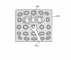
- FIG. 24A is a view showing the relationship between an imaging unit and an object when observing an abnormal part.
- FIG. 24B is an example of the acquired image.
- FIG. 25 is an explanatory diagram of classification processing.
- FIG. 26 is a detailed configuration example of a biological mucous membrane identifying unit in the third embodiment.
- FIG. 27 is a detailed configuration example of the image processing unit in the first modified example of the third embodiment.
- FIG. 28 is a detailed configuration example of the image processing unit in the second modified example of the third embodiment.
- FIG. 29 is a detailed configuration example of the image processing unit in the fourth embodiment.
- FIG. 30 is a detailed structural example of the uneven
- 31 (A) and 31 (B) are explanatory diagrams of processing performed by the surface shape calculation unit.
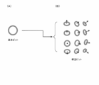
- FIG. 32 (A) shows an example of a basic pit.
- FIG. 32 (B) shows an example of a correction pit.
- FIG. 33 is a detailed configuration example of the surface shape calculation unit.
- FIG. 32 (A) shows an example of a basic pit.
- FIG. 32 (B) shows an example of a correction pit.
- FIG. 33 is a detailed configuration example of the surface shape calculation unit.
- FIG. 34 shows a detailed configuration example of a classification processing unit in the first classification processing method.
- 35 (A) to 35 (F) are explanatory views of a specific example of classification processing.
- FIG. 36 shows a detailed configuration example of a classification processing unit in the second classification processing method.
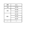
- FIG. 37 shows an example of classification types in the case of using a plurality of classification types.
- FIGS. 38A to 38F show examples of pit patterns.
- Method of this embodiment As a method of emphasizing the unevenness of the subject, there is a method of imaging the subject after the change by causing some change on the subject side.
- the endoscope apparatus for the living body there is a method of staining the living body itself and applying a contrast to the surface mucous membrane by dispersing a pigment such as indigo carmine.
- pigment dispersion is time-consuming and costly, and there is a risk that the inherent pigmentation may impair the original color of the subject, and the visibility of structures other than irregularities may be reduced.
- pigment dispersion to a living body may cause a problem of being highly invasive to the patient.
- the unevenness of the subject is emphasized by image processing.
- the uneven portion itself but also the uneven portion may be classified, and emphasis may be performed according to the classification result.
- the emphasizing process for example, various methods such as reproduction of the pigment dispersion described above and emphasizing of high frequency components can be adopted.
- emphasizing by image processing there is a problem that the unevenness of the subject to be emphasized and the unevenness of the subject not to be emphasized are similarly emphasized.
- the emphasis process is performed on the subject to be emphasized.
- the image is an image of an object (or a scene) to be emphasized, the emphasis process on the object (or the entire image) is excluded or suppressed.
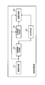
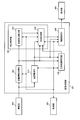
- FIG. 1 shows a first configuration example of an image processing apparatus as a configuration example in the case of performing enhancement processing on a subject to be enhanced.
- the image processing apparatus includes an image acquisition unit 310, a distance information acquisition unit 320, an unevenness specifying unit 350, a biological mucous membrane specifying unit 370, and an emphasis processing unit 340.
- the image acquisition unit 310 acquires a captured image including an image of a subject.
- the distance information acquisition unit 320 acquires distance information based on the distance from the imaging unit to the subject when capturing a captured image.
- the concavo-convex specifying unit 350 specifies the concavo-convex portion of the subject that matches the characteristic identified by the known characteristic information based on the distance information and the known characteristic information that is information representing the known characteristic regarding the structure of the subject. Perform unevenness identification processing.
- the in-vivo mucous membrane identifying unit 370 identifies an area of the in-vivo mucous membrane in the captured image.
- the emphasizing unit 340 emphasizes the identified area of the mucous membrane of the living body based on the information of the uneven portion specified by the uneven part specifying process.
- this configuration example it is possible to specify a living body mucous membrane which is a subject to be emphasized, and to perform an emphasizing process on the specified living body mucous membrane. That is, it is possible to apply emphasis processing to a living mucous membrane and not apply or suppress emphasizing processing to a region other than a living mucous membrane that does not need to be emphasized. This makes it easy for the user to distinguish between the mucous membrane of the living body and the other area, thereby improving the examination accuracy and reducing the user's fatigue.
- the distance information is information in which each position of the captured image is associated with the distance to the subject at each position.
- the distance information is a distance map.
- the distance map for example, when the optical axis direction of the imaging unit 200 in FIG. 3 is the Z axis, the distance (depth / depth) in the Z axis direction to the subject at each point (for example, each pixel) in the XY plane Is a map with the value of that point.
- the distance information may be various information acquired based on the distance from the imaging unit 200 to the subject. For example, in the case of triangulation with a stereo optical system, a distance based on an arbitrary point on a surface connecting two lenses generating parallax may be used as distance information. Alternatively, in the case of using the Time of Flight method, for example, a distance based on each pixel position of the imaging device surface may be acquired as distance information.
- the reference point for distance measurement is set in the imaging unit 200, but the reference point is an arbitrary location other than the imaging unit 200, for example, an arbitrary location in a three-dimensional space including the imaging unit and the subject. It may be set, and information when using such a reference point is also included in the distance information of the present embodiment.
- the distance from the imaging unit 200 to the subject may be, for example, the distance from the imaging unit 200 to the subject in the depth direction.
- the distance in the optical axis direction of the imaging unit 200 may be used.
- the viewpoint is set in a direction perpendicular to the optical axis of the imaging unit 200, the distance observed from the viewpoint (from the imaging unit 200 on the line parallel to the optical axis passing through the Distance)).
- the distance information acquisition unit 320 performs a known coordinate conversion process on the coordinates of each corresponding point in the first coordinate system with the first reference point of the imaging unit 200 as the origin, as a second coordinate in the three-dimensional space.
- the coordinates may be converted into the coordinates of the corresponding point in the second coordinate system with the reference point as the origin, and the distance may be measured based on the converted coordinates.
- the distance from the second reference point in the second coordinate system to each corresponding point is the distance from the first reference point in the first coordinate system to each corresponding point, that is, “the corresponding points from the imaging unit The distance between the two is the same.
- the distance information acquisition unit 320 is virtual at a position where the same magnitude relationship as the magnitude relationship between distance values between pixels on the distance map acquired when the reference point is set in the imaging unit 200 can be maintained.
- distance information based on the distance from the imaging unit 200 to the corresponding point may be acquired. For example, when the actual distances from the imaging unit 200 to the three corresponding points are “3”, “4”, and “5”, for example, the distance information acquiring unit 320 maintains the magnitude relationship of the distance values between the pixels. It is also possible to obtain “1.5”, “2”, “2.5” in which the distances are uniformly halved. As described later in FIG.
- the unevenness information acquisition unit 380 acquires unevenness information using the extraction processing parameter
- the unevenness information acquisition unit 380 extracts as compared with the case where the reference point is set in the imaging unit 200.
- Different parameters will be used as processing parameters. Since it is necessary to use distance information to determine the extraction processing parameter, the method of determining the extraction processing parameter also changes when the way of representing the distance information is changed due to the change of the reference point of the distance measurement. For example, when extracting extraction unevenness information by morphology processing as described later, the size (for example, the diameter of a sphere) of the structural element used for the extraction process is adjusted, and extraction of the unevenness portion is performed using the adjusted structural element Perform the process.
- the known characteristic information is information which can separate the structure useful in the present embodiment and the structure not so among the structures of the object surface.
- information on uneven portions that is useful to emphasize may be used as known characteristic information, in which case a subject that matches the known characteristic information is the target of emphasis processing.
- a structure that is not useful even if emphasized may be used as known characteristic information, in which case an object that does not match the known characteristic information is to be emphasized.
- information on both the useful unevenness and the non-useful structure may be held, and the range of the useful unevenness may be set with high accuracy.
- the known characteristic information is information that can classify the structure of the subject into a particular type or state.
- it is information for classifying a structure of a living body into types such as blood vessels, polyps, cancer, and other lesions, and information such as shape, color, size, etc. characteristic of those structures.
- it may be information that can determine whether a specific structure (for example, a pit pattern present in the large intestine mucosa) is normal or abnormal, etc., and the shape of the normal or abnormal structure. It may be information such as color and size.
- the area of the in-vivo mucous membrane is not limited to the entire in-vivo mucous membrane shown in the captured image, but a part thereof may be specified as the in-vivo mucous membrane. That is, the part which is the implementation object of emphasis processing among the body mucous membranes should just be specified as a field of the body mucous membrane.
- a groove region which is a part of the surface of the living body is specified as a region of the living mucous membrane, and the region is emphasized.
- a portion where a feature (for example, color) other than the unevenness on the surface of the living body meets a predetermined condition is specified as the region of the living mucous membrane.
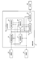
- FIG. 2 shows a second configuration example of the image processing apparatus as a configuration example in the case of excluding or suppressing enhancement processing on a subject (or a scene) that should not be enhanced.
- the image processing apparatus includes an image acquisition unit 310, a distance information acquisition unit 320, an unevenness information acquisition unit 380, an exclusion target identification unit 330, and an emphasis processing unit 340.
- the image acquisition unit 310 acquires a captured image including an image of a subject.
- the distance information acquisition unit 320 acquires distance information based on the distance from the imaging unit to the subject when capturing a captured image.
- the concavo-convex specifying unit 350 specifies the concavo-convex portion of the subject that matches the characteristic identified by the known characteristic information based on the distance information and the known characteristic information that is information representing the known characteristic regarding the structure of the subject. Perform unevenness identification processing.
- the emphasizing processing unit 340 performs emphasizing processing on the captured image based on the information of the concavo-convex portion specified by the concavo-convex specifying processing.
- the exclusion target specifying unit 330 specifies an exclusion target area in the captured image for which enhancement processing is not performed. At this time, the emphasizing processing unit 340 does not apply or suppresses emphasizing processing on the identified exclusion target area.
- the emphasizing process is applied to the area other than the exclusion target, and as a result, the emphasizing process can be performed on the biological mucous membrane to be emphasized. This makes it easy for the user to distinguish between the mucous membrane of the living body and the other area, thereby improving the examination accuracy and reducing the user's fatigue.
- the exclusion target is a subject or scene that does not need to be emphasized (for example, not a living body) or a subject or a scene that is not useful to emphasize (for example, to enhance the doctor's medical examination by emphasizing).
- a subject such as a residue or a blood clot, a treatment tool, a sunken (blackout) area, a whiteout (highlight) area, or a treatment with, for example, water supply or IT knife.
- mist is generated when the knife cauterizes a living body. If an image in which such mist is captured is enhanced, there is a possibility that the image will be rather difficult to observe.
- the enhancement processing of the area is not applied (or suppressed), and in the case of an image obtained by capturing the scene to be excluded, the entire image Do not apply (or suppress) emphasis processing of
- a local uneven structure eg, polyp, eyebrows, etc.
- a desired size eg, width, height, depth, etc.
- the extraction process is performed excluding the global structure (for example, the surface undulation larger than the scale).
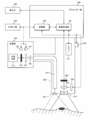
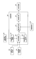
- FIG. 3 shows an example of the configuration of the endoscope apparatus according to the first embodiment.
- the endoscope apparatus includes a light source unit 100, an imaging unit 200, a processor unit 300, a display unit 400, and an external I / F unit 500.
- the light source unit 100 includes a white light source 110, a light source diaphragm 120, a light source diaphragm driving unit 130 for driving the light source diaphragm 120, and a rotational color filter 140 having filters of a plurality of spectral transmittances.
- the light source unit 100 also includes a rotary drive unit 150 for driving the rotary color filter 140, and a condenser lens 160 for condensing light transmitted through the rotary color filter 140 on the incident end face of the light guide fiber 210.
- the light source diaphragm drive unit 130 adjusts the light amount by opening and closing the light source diaphragm 120 based on a control signal from the control unit 302 of the processor unit 300.
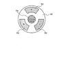
- FIG. 4 shows a detailed configuration example of the rotary color filter 140.
- the rotating color filter 140 is composed of three primary color red (abbreviated as R) filters 701, a green (abbreviated as G) filter 702, a blue (abbreviated as B) filter 703, and a rotating motor 704.
- R red
- G green
- B blue
- the R filter 701 transmits light having a wavelength of 580 nm to 700 nm
- the G filter 702 transmits light having a wavelength of 480 nm to 600 nm
- the B filter 703 transmits light having a wavelength of 400 nm to 500 nm.
- the rotation drive unit 150 rotates the rotation color filter 140 at a predetermined rotation speed in synchronization with the imaging period of the imaging device 260 based on the control signal from the control unit 302. For example, if the rotary color filter 140 is rotated 20 times per second, each color filter will cross incident white light at intervals of 1/60 second. In this case, the imaging device 260 completes the imaging and transfer of the image signal at an interval of 1/60 of a second.
- the imaging device 260 is, for example, a monochrome single-plate imaging device, and is configured of, for example, a CCD, a CMOS image sensor, or the like. That is, in the present embodiment, imaging in a plane-sequential method is performed in which images of respective primary colors (R, G, or B) of three primary colors are captured at an interval of 1/60 second.
- the imaging unit 200 is formed to be elongated and bendable, for example, to allow insertion into a body cavity.
- the imaging unit 200 diffuses the light guided to the tip by the light guide fiber 210 for guiding the light collected by the light source unit 100 to the illumination lens 220 and irradiates the observation target with the light And an illumination lens 220.
- the imaging unit 200 includes an objective lens 230 for condensing reflected light returning from an observation target, a focus lens 240 for adjusting a focal position, and a lens driving unit 250 for moving the position of the focus lens 240.
- an imaging element 260 for detecting the collected reflected light.
- the lens driving unit 250 is, for example, a VCM (Voice Coil Motor), and is connected to the focus lens 240.
- the lens drive unit 250 adjusts the in-focus object position by switching the position of the focus lens 240 at a continuous position.
- the imaging unit 200 is provided with a switch 270 for allowing the user to instruct on / off of the emphasizing process.
- a switch 270 for allowing the user to instruct on / off of the emphasizing process.
- an on / off instruction signal of enhancement processing is output from the switch 270 to the control unit 302.
- the imaging unit 200 also includes a memory 211 in which information of the imaging unit 200 is recorded.
- a scope ID indicating the use of the imaging unit 200
- information of optical characteristics of the imaging unit 200 information of a function of the imaging unit 200, and the like are recorded.
- the scope ID is, for example, an ID corresponding to a scope for the lower digestive tract (large intestine) or a scope for the upper digestive tract (esophagus, stomach).
- the information of the optical characteristic is, for example, information such as the magnification (angle of view) of the optical system.
- the information of the function is information representing the execution state of the function such as water supply provided in the scope.
- the processor unit 300 (control device) performs control of each unit of the endoscope apparatus and image processing.
- the processor unit 300 includes a control unit 302 and an image processing unit 301.
- the control unit 302 is bidirectionally connected to each unit of the endoscope apparatus, and controls each unit. For example, the control unit 302 transfers the control signal to the lens drive unit 250 to change the position of the focus lens 240.
- the image processing unit 301 performs a process of specifying an area of a biological mucous membrane from a captured image, an enhancement process of the specified area of a biological mucous membrane, and the like. Details of the image processing unit 301 will be described later.
- the display unit 400 displays the endoscopic image transferred from the processor unit 300.
- the display unit 400 is an image display device capable of displaying moving images, such as an endoscope monitor, for example.
- the external I / F unit 500 is an interface for performing input from the user to the endoscope apparatus.
- the external I / F unit 500 starts, for example, a power switch for turning on / off the power, a mode switching button for switching the shooting mode and other various modes, and an autofocus operation for automatically focusing on the subject.
- Is configured to include an AF button and the like.
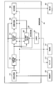
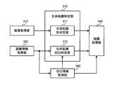
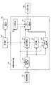
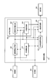
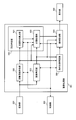
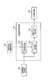
- FIG. 5 shows a configuration example of the image processing unit 301 in the first embodiment.
- the image processing unit 301 includes an image acquisition unit 310, a distance information acquisition unit 320, a biological mucous membrane identification unit 370, an emphasis processing unit 340, a post-processing unit 360, an unevenness identification unit 350, and a storage unit 390.
- the unevenness identification unit 350 includes an unevenness information acquisition unit 380.
- the image acquisition unit 310 is connected to the distance information acquisition unit 320, the biological mucous membrane identification unit 370, and the emphasis processing unit 340.
- the distance information acquisition unit 320 is connected to the in-vivo mucous membrane identification unit 370 and the unevenness information acquisition unit 380.
- the biological mucous membrane identification unit 370 is connected to the emphasis processing unit 340.
- the emphasizing processing unit 340 is connected to the post-processing unit 360.
- the post-processing unit 360 is connected to the display unit 400.
- the unevenness information acquisition unit 380 is connected to the in-vivo mucous membrane identification unit 370 and the emphasis processing unit 340.
- the storage unit 390 is connected to the unevenness information acquisition unit 380.
- the control unit 302 is bidirectionally connected to each unit of the image processing unit 301, and controls each unit. For example, the control unit 302 synchronizes the image acquisition unit 310, the post-processing unit 360, and the light source aperture drive unit 130. Further, the switch 270 (or the external I / F unit 500) transfers an emphasis processing on / off instruction signal to the emphasis processing unit 340.
- the image acquisition unit 310 converts an analog image signal transferred from the imaging device 260 into a digital image signal by A / D conversion processing. Then, OB clamp processing, gain correction processing, and WB correction processing are performed on the digital image signal using the OB clamp value, gain correction value, and WB coefficient value stored in advance in the control unit 302. Further, the synchronization processing is performed on the R image, the G image, and the B image captured by the field sequential method, and a color image having RGB pixel values for each pixel is acquired. The color image is transferred as an endoscopic image (captured image) to the distance information acquisition unit 320, the biological mucous membrane identification unit 370, and the emphasis processing unit 340.
- the A / D conversion process may be performed at a stage before the image processing unit 301 (for example, built in the imaging unit 200).
- the distance information acquisition unit 320 acquires distance information to the subject based on the endoscope image, and transfers the distance information to the biological mucous membrane identification unit 370 and the unevenness information acquisition unit 380.
- the distance information acquisition unit 320 detects the distance to the subject by calculating the blur parameter from the endoscopic image.
- the imaging unit 200 may have an optical system for capturing a stereo image, and the distance information acquisition unit 320 performs stereo matching processing on the stereo image to detect the distance to the subject. Good.
- the imaging unit 200 may have a sensor that detects TOF (Time Of Flight), and the distance information acquisition unit 320 may detect the distance to the subject based on the sensor output. The details of the distance information acquisition unit 320 will be described later.
- TOF Time Of Flight
- the distance information is, for example, a distance map having distance information corresponding to each pixel of the endoscopic image.
- the distance information includes both information representing the rough structure of the subject and information representing the unevenness relatively smaller than the rough structure.
- the information representing the rough structure corresponds to, for example, the rough structure of the luminal structure or mucous membrane originally possessed by the organ, and is, for example, a low frequency component of distance information.
- the information representing the unevenness corresponds to, for example, the unevenness of the mucous membrane surface or the lesion, and is, for example, a high frequency component of the distance information.
- the concavo-convex information acquisition unit 380 extracts the extracted concavo-convex information representing the concavo-convex part on the surface of the living body from the distance information, based on the known characteristic information stored in the storage unit 390. Specifically, the concavo-convex information acquisition unit 380 acquires, as known characteristic information, the size (dimension information such as width, height, depth, etc.) of the concavo-convex portion unique to the living body desired to be extracted, and the desired dimension represented by the known characteristic information. Extract asperities having characteristics. Details of the unevenness information acquisition unit 380 will be described later.
- the biological mucous membrane identification unit 370 identifies an area of a biological mucous membrane (for example, a part of a biological body in which a lesion may be present) to be subjected to enhancement processing in an endoscopic image. As described later, for example, based on an endoscopic image, a region that matches the color feature of the in-vivo mucous membrane is specified as the in-vivo mucous membrane region.
- a region matching the feature of the biological mucous membrane (for example, a recess or a groove) to be emphasized is specified as a region of the biological mucous membrane among the concavity and convexity represented by the extracted concavity and convexity information.
- the in-vivo mucous membrane identification unit 370 determines whether each pixel is in-vivo mucous membrane, and outputs positional information (coordinates) of the pixel determined to be in-vivo mucous membrane to the emphasis processing unit 340.
- a set of pixels determined to be the in-vivo mucous membrane corresponds to the area of the in-vivo mucous membrane.
- the emphasizing processing unit 340 performs emphasizing processing on the identified area of the mucous membrane of the living body, and outputs the endoscopic image to the post-processing unit 360.
- the biological mucous membrane identification unit 370 specifies the region of the biological mucous membrane by color
- the emphasizing unit 340 emphasizes the region of the biological mucous membrane based on the extracted unevenness information.
- the in-vivo mucous membrane identification unit 370 identifies the area of the in-vivo mucous membrane based on the extracted unevenness information
- the emphasizing unit 340 emphasizes the in-vivo mucous membrane area. In any case, the emphasizing process is performed based on the extracted unevenness information.
- the emphasizing process may be, for example, a process of emphasizing a concavo-convex structure (for example, a high frequency component of an image) of a living mucous membrane, or a process of emphasizing a predetermined color component according to the concavo-convex of the living mucous membrane.
- processing for reproducing pigment dispersion may be performed by making predetermined color components darker in concave portions than in convex portions.
- the post-processing unit 360 performs tone conversion on the endoscope image transferred from the enhancement processing unit 340 using tone conversion coefficients, color conversion coefficients, and edge enhancement coefficients stored in advance in the control unit 302. Performs processing, color processing, and edge enhancement processing.
- the post-processing unit 360 transfers the post-processed endoscopic image to the display unit 400.
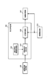
- FIG. 6 shows a detailed configuration example of the biological mucous membrane identification unit 370.
- the biological mucous membrane identification unit 370 includes a biological mucous membrane color judgment unit 371 and a biological mucous membrane unevenness judgment unit 372.
- at least one of the in-vivo mucous membrane color determination unit 371 and the in-vivo mucous membrane unevenness determination unit 372 identifies the region of the in-vivo mucous membrane.
- the endoscopic image is transferred from the image acquisition unit 310 to the in-vivo mucous membrane color determination unit 371.
- the biological mucous membrane color determination unit 371 compares the hue value at each pixel of the endoscopic image with the range of hue values possessed by the biological mucous membrane, and determines whether each pixel corresponds to the biological mucous membrane.
- a pixel whose hue value H satisfies the following expression (1) is determined as a pixel corresponding to a biological mucous membrane (hereinafter referred to as a biological mucous membrane pixel). 10 ° ⁇ H ⁇ 30 ° (1)
- the hue value H is calculated from the RGB pixel values by the following equation (2), and takes a range of 0 ° to 360 °.
- max (R, G, B) is the maximum value among R pixel value, G pixel value, and B pixel value
- min (R, G, B) is R pixel value, G pixel Value, which is the minimum value of B pixel values.
- the emphasizing process can be performed by limiting to a region in which the in-vivo mucous membrane can be determined from the color feature. As a result, it is possible to perform an emphasizing process suitable for medical examination, in order not to emphasize a subject that does not need to be emphasized.
- the distance information is transferred from the distance information acquisition unit 320 to the biological mucous membrane unevenness determination unit 372, and the extracted unevenness information is transferred from the unevenness information acquisition unit 380.
- the biological mucous membrane unevenness judgment unit 372 judges whether each pixel corresponds to a biological mucous membrane based on the distance information and the extracted unevenness information. Specifically, based on the extracted asperity information, a groove on the surface of the living body (for example, a recess with a width of 1000 ⁇ m or less (including its value) and a depth of 100 ⁇ m or less (including its value)) is detected.
- the above equation (4) represents that the pixel at the coordinates (p, q) is a pixel detected as a groove on the surface of the living body.
- D (x, y) is the distance to the subject at the pixel at coordinate (x, y)
- D (p, q) is the distance to the subject at the pixel at coordinate (p, q) It is a distance.
- Tneighbor is a threshold for the distance difference between pixels.
- the distance information acquisition unit 320 acquires a distance map as distance information.
- the distance map means, for example, the distance (depth / depth) in the Z-axis direction to the subject at each point (for example, each pixel) in the XY plane when the optical axis direction of the imaging unit 200 is the Z axis. It is the map which made the value of the point concerned.
- the distance D (x, y) at the coordinate (x, y) of the endoscopic image is the coordinate (x, y) of the distance map. It is the value in).
- the biological mucous membrane on which enhancement processing is to be performed is specified in the endoscopic image, and the specified biological mucous membrane on the subject surface is Emphasize unevenness information.
- the emphasizing process can be performed on the area requiring the emphasizing process, so the ability to distinguish between the area requiring the emphasizing process and the area not requiring the emphasizing process is improved, and the user feels tired in image observation when the emphasizing process is performed. Can be minimized.
- the biological mucous membrane specifying unit 370 specifies a region in which the feature amount based on the pixel value of the captured image satisfies the predetermined condition corresponding to the biological mucous membrane as the region of the biological mucous membrane. More specifically, the in-vivo mucous membrane identification unit 370 uses, as the in-vivo mucous membrane area, a region in which color information (for example, hue value) that is a feature amount satisfies a predetermined condition (for example, a range of hue values) Identify.
- a predetermined condition for example, a range of hue values
- the subject to be emphasized can be identified based on the feature amount of the image. That is, by setting the feature of the mucous membrane of the living body as the condition of the feature amount and detecting the region meeting the predetermined condition, it is possible to specify the subject to be emphasized. For example, by setting a color characteristic of the mucous membrane of the living body as a predetermined condition, it is possible to specify an area matching the color condition as a subject to be emphasized.
- the in-vivo mucous membrane identifying unit 370 identifies an area in which the extracted asperity information matches the asperity characteristic that is the known characteristic information as the in-vivo mucous membrane area. More specifically, the in-vivo mucous membrane identification unit 370 acquires, as known characteristic information, dimension information representing at least one of the width and the depth of the recess (groove) of the subject, and among the irregularities included in the extracted unevenness information, Extract a recess that matches the characteristics specified by the dimension information. Then, the recessed area which is an area on the captured image corresponding to the extracted recessed area and the area near the recessed area are specified as the area of the mucous membrane of the living body.
- the subject to be emphasized can be identified based on the uneven shape of the subject. That is, by setting the feature of the mucous membrane of the living body as the condition of the concavo-convex shape and detecting the region meeting the predetermined condition, the subject to be emphasized can be specified. Further, by specifying the recessed area as the area of the mucous membrane of the living body, the emphasizing process can be performed on the recessed area. As will be described later, in the case of dye dispersion, since the concave portions on the surface of the living body tend to be dyed deeply, it is possible to reproduce the dye dispersion by image processing by emphasizing the concave portions.
- the concavo-convex characteristic is a characteristic of the concavo-convex portion specified by the concavo-convex characteristic information.
- the asperity characteristic information is information for specifying the asperity characteristic of the subject that is desired to be extracted from the distance information. Specifically, it includes at least one of information indicating the characteristics of the unevenness to be non-extracted and the information indicating the characteristics of the unevenness to be extracted among the unevenness included in the distance information.
- the emphasizing process is performed such that the emphasizing process is turned on for the area of the mucous membrane of the living body and the emphasizing process is turned off for the other areas.
- the emphasizing processing unit 340 performs emphasizing processing with an emphasizing amount that changes continuously at the boundary between the region of the mucous membrane of the body and the other region.
- the amount of enhancement is multi-valued (for example, 0% to 100%) by applying a low-pass filter to the amount of enhancement at the boundary between the region of the body mucous membrane and the other region. Make it continuous.
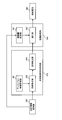
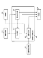
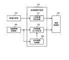
- FIG. 8 shows a detailed configuration example of the unevenness information acquisition unit 380.
- the unevenness information acquisition unit 380 includes a known characteristic information acquisition unit 381, an extraction processing unit 383 and an extraction unevenness information output unit 385.
- an uneven portion having a desired dimension characteristic (in a narrow sense, an uneven portion whose width is in a desired range) is extracted as extracted uneven information. Since the three-dimensional structure of the subject is reflected in the distance information, the distance information is a rough surface corresponding to the eyebrow structure, which is a larger structure than the desired uneven portion, and the wall surface structure of the lumen. Structure is included. That is, it can also be said that the extraction unevenness information acquisition process of the present embodiment is a process of excluding the eyelid structure and the lumen structure from the distance information.
- the extraction unevenness information acquisition process is not limited to this.
- the known characteristic information may not be used in the process of acquiring the extracted unevenness information.
- various modifications can be made as to what kind of information is used as the known characteristic information.
- information on lumen structure may be excluded from distance information, but extraction processing may be performed to leave information on hemorrhoid structure.
- known property information for example, dimension information of a recess
- the known characteristic information acquisition unit 381 acquires known characteristic information from the storage unit 390. Specifically, the size of the unevenness inherent in the living body that is desired to be extracted from the lesion surface (dimension information such as width, height, depth, etc.), and the size of the area specific lumen and fold based on the observation area information ( Dimension information such as width, height, and depth is acquired as known characteristic information.
- the observation site information is information indicating a site to be observed, which is determined based on, for example, scope ID information, and the observation site information may also be included in the known characteristic information.
- the observation site is the esophagus, the stomach, and the duodenum
- the observation site is the information determined to be the large intestine. Since the dimension information of the uneven portion to be extracted and the lumen and ⁇ region specific information of the region are different depending on the region, the known characteristic information acquisition unit 381 obtains the standard information acquired based on the observation region information. The information such as the size of the lumen and the fistula is output to the extraction processing unit 383.
- the observation site information is not limited to the one determined by the scope ID information, but may be determined by another method such as being selected using a switch operable by the user in the external I / F unit 500.
- the extraction processing unit 383 determines an extraction processing parameter based on the known characteristic information, and performs extraction processing of the extracted unevenness information based on the determined extraction processing parameter.
- the extraction processing unit 383 performs low-pass filter processing of a predetermined size of N ⁇ N pixels on the input distance information to extract rough distance information. Then, based on the extracted rough distance information, an extraction processing parameter is determined adaptively. Details of the extraction processing parameters will be described later, for example, the kernel size of the morphology (size of structural element) adapted to the distance information at the plane position orthogonal to the distance information of the distance map or the distance information of the plane position. It is the low pass characteristic of the adapted low pass filter or the high pass characteristic of the high pass filter adapted to the planar position. That is, it is change information for changing an adaptive non-linear and linear low-pass filter or high-pass filter according to distance information.
- the low-pass filter processing here is intended to suppress the reduction in the accuracy of the extraction processing due to frequent or extreme changes of the extraction processing parameters according to the position on the image, and the accuracy reduction is a problem. If not, it is not necessary to perform low pass filter processing.
- the extraction processing unit 383 performs extraction processing based on the determined extraction processing parameter, thereby extracting only the uneven portion of a desired size existing in the subject.
- the extraction concavo-convex information output unit 385 sends the extracted concavo-convex portion to the biological mucous membrane identification unit 370 or the emphasis processing unit 340 as extraction concavo-convex information (concave and convexity image) of the same size as the captured image (image to be enhanced). Output.
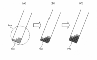
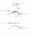
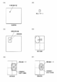
- FIGS. 9A to 9F are the diameters of structural elements (spheres) used for the opening processing of the morphological processing and the closing processing.
- FIG. 9A is a view schematically showing a cross section in the vertical direction of the living body surface of the subject and the imaging unit 200.
- the wrinkles 2, 3 and 4 on the living body surface are, for example, the wrinkles of the stomach wall. Further, it is assumed that the early lesions 10, 20, 30 are formed on the surface of the living body.
- the extraction processing parameter determination processing in the extraction processing unit 383 is the extraction for extracting only the early lesions 10, 20, 30 without extracting the wrinkles 2, 3, 4 from such a living body surface It is to determine processing parameters.
- the diameter of the sphere is smaller than the size of the region-specific lumen and eyebrow based on the observation region information, and the diameter is set larger than the size of the body-specific unevenness to be extracted due to the lesion. More specifically, it is preferable to set the diameter smaller than half of the size of the eyebrows to be equal to or larger than the size of the unevenness inherent in the living body to be extracted due to the lesion.
- FIGS. 9 (A) to 9 (F) An example in which a sphere satisfying the above conditions is used for the opening process and the closing process is depicted in FIGS. 9 (A) to 9 (F).
- FIG. 9 (B) shows the surface of the living body after the closing process.
- extraction processing parameters size of the structural element
- extraction is performed while maintaining the distance change due to the biological wall and the structure such as wrinkles. It can be seen that, among the uneven portions of the target dimension, information in which the concave portion is filled can be obtained.
- FIG. 9C By taking the difference between the information obtained by the closing process and the original living body surface (corresponding to FIG. 9A), it is possible to extract only the recess on the living body surface as shown in FIG. 9C.
- FIG. 9D shows the surface of the living body after the opening process, and it is understood that among the uneven portions of the dimension to be extracted, information in which the convex portion is scraped can be obtained. Therefore, by taking the difference between the information obtained by the opening process and the original living body surface, it is possible to extract only the convex portion of the living body surface as shown in FIG. 9 (E).
- control may be performed to increase the diameter of the sphere when the distance information is close and reduce the diameter of the sphere when the distance information is far.
- control is performed such that the diameter of the sphere is changed with respect to average distance information in the case of performing opening processing and closing processing on the distance map. That is, in order to extract a desired uneven portion with respect to the distance map, it is necessary to correct with the optical magnification in order to make the real size of the living body surface coincide with the size of the pixel pitch on the image formed on the imaging device . Therefore, it is preferable that the extraction processing unit 383 acquire the optical magnification and the like of the imaging unit 200 determined based on the scope ID information.
- the size of a structural element which is the extraction process parameter when the process by the structural element is performed on the shape which is a non-extraction object such as a weir (in FIG. In the case of (1), the size of a structural element which does not collapse the shape (the ball moves following the shape) is determined.
- the processing by the structural element is performed on the uneven portion to be extracted as the extracted uneven portion information, the uneven portion is eliminated (if it is slid from above, it does not enter into the depressed portion, or is slid from below) In such a case, the size of the structural element which does not enter the convex portion) may be determined.
- the morphological processing is a widely known method, so detailed description will be omitted.
- the asperity information acquisition unit 380 determines the extraction processing parameter based on the known characteristic information, and extracts the asperity portion of the subject as the extraction asperity information based on the determined extraction process parameter.
- extraction processing for example, separation processing
- a specific method of the extraction process may be considered to be the morphological process described above, a filter process described later, etc., in any case, in order to accurately extract the extracted unevenness information, information of various structures included in the distance information From this, it is necessary to control to exclude other structures (for example, a structure unique to a living body such as wrinkles) while extracting information on a desired uneven portion.
- control is realized by setting extraction processing parameters based on known characteristic information.
- the captured image is an in-vivo image obtained by imaging the inside of a living body
- the known characteristic information acquisition unit 381 indicates region information indicating which part of the living body the subject corresponds to; Concavo-convex characteristic information which is information on a part may be acquired as known characteristic information.
- the asperity information acquisition unit 380 determines an extraction processing parameter based on the part information and the asperity characteristic information.
- the site information on the site of the subject of the in-vivo image is , It becomes possible to acquire as known characteristic information.
- extraction of a concavo-convex structure useful for detection of an early lesion and the like as extraction concavities and convexity information is assumed.
- the characteristics (for example, dimension information) of the uneven portion may differ depending on the part.
- the structure unique to the living body to be excluded such as wrinkles naturally varies depending on the site. Therefore, if a living body is targeted, it is necessary to perform appropriate processing according to the site, and in the present embodiment, the process is performed based on the site information.
- the unevenness information acquisition unit 380 determines the size of the structural element used for the opening process and the closing process as the extraction process parameter based on the known property information, and uses the structural element of the determined size.
- the opening process and closing process described above are performed to extract the uneven portion of the subject as the extracted uneven information.
- the extraction process parameter at that time is the size of the structural element used in the opening process and the closing process. Since a sphere is assumed as a structural element in FIG. 9A, the extraction processing parameter is a parameter that represents the diameter of the sphere and the like.
- the extraction process of the present embodiment is not limited to the morphological process, and may be performed by a filter process.
- the unevenness inherent in the living body desired to be extracted due to the lesion can be smoothed, and the characteristics of the low pass filter in which the structure of the lumen and eyebrow specific to the observation site is retained are determined. Since the characteristics of the uneven portion to be extracted, the wrinkles to be excluded, and the lumen structure are known from the known characteristic information, their spatial frequency characteristics become known, and the characteristics of the low pass filter can be determined.
- the low-pass filter may be a well-known Gaussian filter or bilateral filter, the characteristics of which are controlled by ⁇ , and a ⁇ map corresponding to the pixels of the distance map may be created (in the case of the bilateral filter, ⁇ of the luminance difference
- the ⁇ map may be created by using either one or both of the distances ⁇ ).
- the Gaussian filter can be expressed by the following equation (5)
- the bilateral filter can be expressed by the following equation (6).
- a thinned ⁇ map may be created, and a desired low-pass filter may be applied to the distance map by the ⁇ map.
- the ⁇ which determines the characteristics of the low-pass filter is, for example, larger than a predetermined multiple ⁇ (> 1) of the interpixel distance D1 of the distance map corresponding to the size of the unevenness unique to the living body to be extracted
- a value smaller than a predetermined multiple ⁇ ( ⁇ 1) of the inter-pixel distance D2 of the distance map corresponding to the size is set.
- ⁇ ( ⁇ * D1 + ⁇ * D2) / 2 * R ⁇ may be used.
- the filter characteristic is controlled not by ⁇ but by the cutoff frequency fc.
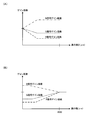
- R ⁇ is a function of the local average distance, and the output value increases as the local average distance decreases, and decreases as the local average distance increases.
- Rf is a function in which the output value decreases as the local average distance decreases and increases as the local average distance increases.
- the recess image can be output by subtracting the low pass processing result from the distance map not subjected to the low pass processing and extracting only a region that is negative. Further, the convex image can be output by subtracting the low-pass processing result from the distance map not subjected to the low-pass processing and extracting only a region that is positive.
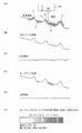
- FIGS. 10 (A) to 10 (D) show explanatory views of a process of extracting a desired uneven portion derived from a lesion by a low pass filter.
- filter processing using a low pass filter on the distance map of FIG. 10A, as shown in FIG. 10B, while maintaining the distance change due to the living body wall surface and the structure such as wrinkles, It can be seen that information can be obtained from which the uneven portion of the dimension to be extracted has been removed.
- the low pass filter processing results in the reference phase (FIG. 10 (B)) for extracting the desired uneven portion even without performing the opening processing and the closing processing as described above, the distance map (FIG. 10 (A) By the subtraction process with), the uneven portion can be extracted as shown in FIG.
- FIG. 10 (D) An example is shown in FIG. 10 (D).
- high pass filter processing may be performed instead of low pass filter processing, in which case a high pass filter which holds the unevenness inherent in the living body to be extracted due to the lesion and cuts the structure of the lumen and eyebrow specific to the observation site Determine the characteristics.
- the filter characteristic is controlled at the cutoff frequency fhc.
- the cutoff frequency fhc may be specified to pass the frequency F1 of the D1 cycle and to cut the frequency F2 of the D2 cycle.
- Rf is a function in which the output value decreases as the local average distance decreases, and increases as the local average distance increases.
- the high-pass filter processing it is possible to extract an uneven portion to be extracted directly from the lesion. Specifically, as shown in FIG. 10C, the extracted asperity information is directly acquired without taking the difference.
- the concavo-convex information acquisition unit 380 determines the frequency characteristic of the filter used for the filtering process on the distance information as the extraction process parameter based on the known characteristic information, and determines the determined frequency characteristic.
- a filtering process using a filter is performed to extract the uneven portion of the subject as extracted uneven information.
- the extraction processing parameter at that time is the characteristic (spatial frequency characteristic in a narrow sense) of the filter used in the filter processing.
- the value of ⁇ and the cut-off frequency may be determined based on the frequency corresponding to the exclusion target such as wrinkles and the frequency corresponding to the uneven portion.
- Body mucous membrane unevenness judgment processing emphasizing processing
- the body mucous membrane unevenness judgment unit 372 extracts a recess on the surface of the living body (hereinafter referred to as a groove) and its vicinity as a biological mucous membrane, and the emphasizing processor 340 emphasizes the area of the biological mucous membrane
- the process to be performed will be described in detail.
- an image simulating an image in which indigo carmine is dispersed to improve the contrast of a minute uneven portion on the surface of a living body is created.
- the pixel values of the groove area and the neighboring area are multiplied by a gain that increases bluish.
- the extracted asperity information transferred from the asperity information acquisition unit 380 is in one-to-one correspondence with the endoscopic image input from the image acquisition unit 310 for each pixel.
- FIG. 11 shows a detailed configuration example of the biological mucous membrane unevenness judgment unit 372.
- the biological mucous membrane unevenness determination unit 372 includes a dimension information acquisition unit 601, a recess extraction unit 602, and a vicinity extraction unit 604.
- the dimension information acquisition unit 601 acquires known characteristic information (here, particularly, dimension information) from the storage unit 390 or the like.
- the concave portion extraction unit 602 extracts the concave portion to be emphasized among the concave and convex portions included in the extracted concave and convex information based on the known characteristic information.
- the vicinity extraction unit 604 extracts the surface of the living body within (a vicinity of) a predetermined distance from the extracted recess.
- the groove of the biological body surface is detected from the extracted unevenness information based on the known characteristic information.
- the known characteristic information refers to the width and depth of the groove on the surface of the living body.
- the width of a minute groove on the surface of a living body is several thousand ⁇ m or less (including its value), and the depth is several hundred ⁇ m or less (including its value).
- the width and the depth of the groove on the surface of the living body are calculated from the extracted unevenness information.
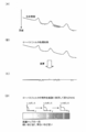
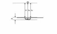
- FIG. 12 shows one-dimensional extracted asperity information.
- the distance from the imaging element 260 to the surface of the living body is assumed to be a positive value in the depth direction, with the position of the imaging element 260 (imaging surface) being zero.
- FIG. 13 shows a method of calculating the width of the groove.
- the end of a point separated by a threshold value x1 or more (including that value) from the imaging plane which is farther than the reference plane is detected (Points A and B in FIG. 13) ).
- the distance x1 is a reference plane.
- the number N of pixels corresponding to the inside of the detected point is calculated.
- the average value of the distances x1 to xN from the image pickup element is calculated with respect to the internal point, and is defined as xave.
- the equation for calculating the width w of the groove is shown in the following equation (7).
- p is the width per pixel of the imaging device 260
- K is the optical magnification corresponding to the distance xave from the imaging device on a one-to-one basis.
- w N x p x K (7)
- FIG. 14 shows a method of calculating the depth of the groove.
- the formula for calculating the depth d of the groove is shown in the following formula (8).
- the maximum value of x1 to xN is xM
- the smaller one of x1 and xN is xmin.
- d xM-xmin1 (8)
- the user may set an arbitrary value via the external I / F unit 500 for the reference plane (the plane of the distance x1 from the imaging device). If the calculated groove width and depth match the known characteristic information, the pixel position of the corresponding endoscopic image is determined to be a pixel of the groove area. Here, it is determined whether the width of the groove is equal to or less than 3000 ⁇ m (including its value) and the depth of the groove is equal to or less than 500 ⁇ m (including its value). It is determined that the pixel
- the width and depth of the groove serving as the threshold may be set by the user via the external I / F unit 500.
- the proximity extraction unit 604 detects a pixel on the surface of the living body whose distance in the depth direction is within a predetermined distance from the groove area as a proximity pixel.
- the pixels in the groove area and the pixels in the vicinity area are output to the emphasis processing unit 340 as pixels of the biological mucous membrane.
- the emphasis processing unit 340 includes an emphasis amount setting unit 341 and a correction unit 342.
- the emphasizing processing unit 340 multiplies the pixel value of the biological mucous membrane pixel by the gain coefficient. Specifically, the gain coefficient of one or more (including its value) is multiplied to increase the B signal of the pixel of interest, and the gain coefficient of one or less (including its value) is reduced to decrease the R and G signals. Do. As a result, the grooves (recesses) on the surface of the living body can be bluish to obtain an image as if indigo carmine has been dispersed.
- the correction unit 342 performs a correction process that enhances the visibility of the emphasis target. Details will be described later. At this time, the emphasis amount may be set by the emphasis amount setting unit 341 and correction processing may be performed according to the set emphasis amount.
- an on / off instruction signal of enhancement processing is input from the switch 270 and the external I / F unit 500 via the control unit 302.
- the enhancement processing unit 340 transfers the endoscopic image input from the image acquisition unit 310 to the post-processing unit 360 without performing the enhancement processing.
- emphasis processing is performed.
- the enhancement process may be uniformly performed on the biological mucous membrane pixel. Specifically, it is conceivable to perform enhancement processing using the same gain coefficient for all living body mucous membrane pixels.
- the method of emphasizing processing may be changed among the biological mucous membrane pixels that are targets of the emphasizing processing.
- the gain coefficient may be changed according to the width and depth of the groove, and the enhancement processing using the gain coefficient may be performed. Specifically, the gain coefficient is multiplied so that the bluishness becomes thinner as the depth of the groove becomes shallower. By doing this, it is possible to obtain an image close to that obtained by actual dye dispersion.
- An example of setting of the gain coefficient in this case is shown in FIG.
- the fine structure is useful for lesion detection etc.
- the more the amount of emphasis may be, the finer the groove width is, that is, the setting example of the gain coefficient in this case. Is shown in FIG.
- the color to be colored may be changed according to the depth of the groove.
- the continuity of the grooves can be visually recognized as compared with the emphasizing processing in which the same color tone is applied to all the grooves regardless of their depths, and therefore, a more accurate range diagnosis can be performed.
- the gain is increased to raise the B signal and to lower the R and G signals as emphasis processing, but the gain is not limited to this, and the gain is multiplied to increase the B signal and decrease the R signal. There is no need to multiply. As a result, since the signal values of the B and G signals remain even in the concave portion where the bluishness is increased, the structure in the concave portion is displayed in cyan.
- the target of the enhancement processing is not limited to the living body mucous membrane pixels, and the entire image may be processed.
- processing is performed to increase the visibility, such as increasing the gain coefficient, for the region specified as a biological mucous membrane, and the gain coefficient is decreased to 1 for other regions (same as the original color Or conversion to a specific color (for example, to enhance the visibility of the target to be emphasized so as to be complementary to the target color to be emphasized).
- the enhancement processing of the present embodiment is not limited to the generation of a pseudo image similar to that in the case of using indigo carmine, and can be realized by various types of processing for improving the visibility of an object to be noted.
- FIG. 16 shows a detailed configuration example of the distance information acquisition unit 320.
- the distance information acquisition unit 320 includes a luminance signal calculation unit 323, a difference calculation unit 324, a second derivative calculation unit 325, a blur parameter calculation unit 326, a storage unit 327, and a LUT storage unit 328.
- the calculated luminance signal Y is transferred to the difference calculation unit 324, the second derivative calculation unit 325, and the storage unit 327.
- the difference calculation unit 324 calculates the difference of the luminance signal Y from a plurality of images required for blur parameter calculation.
- the second derivative calculation unit 325 calculates a second derivative of the luminance signal Y in the image, and calculates an average value of second derivatives obtained from a plurality of luminance signals Y different in blur.
- the blur parameter calculation unit 326 calculates a blur parameter by dividing the average value of the second derivative calculated by the second derivative calculator 325 from the difference of the luminance signal Y of the image calculated by the difference calculator 324.
- the storage unit 327 stores the luminance signal Y and the result of the second derivative of the first captured image.
- the distance information acquisition unit 320 can arrange the focus lens at different positions via the control unit 302, and acquire a plurality of luminance signals Y at different times.
- the LUT storage unit 328 stores the relationship between the blur parameter and the subject distance in the form of a look-up table (LUT).
- the control unit 302 is bidirectionally connected to the luminance signal calculation unit 323, the difference calculation unit 324, the second derivative calculation unit 325, and the blur parameter calculation unit 326, and controls them.
- the control unit 302 uses the known contrast detection method, phase difference detection method, or the like based on the photographing mode preset by the external I / F unit 500 to obtain the optimum focus lens position. calculate.
- the lens drive unit 250 drives the focus lens 240 to the calculated focus lens position.
- the first image of the subject is acquired by the imaging device 260 at the driven focus lens position.
- the acquired image is stored in the storage unit 327 via the image acquisition unit 310 and the luminance signal calculation unit 323.
- the lens driving unit 250 drives the focus lens 240 to a second focus lens position different from the focus lens position at which the first image was obtained, and the image sensor 260 obtains a second image of the subject. Do.
- the second image thus acquired is output to the distance information acquisition unit 320 via the image acquisition unit 310.
- the difference calculation unit 324 reads the luminance signal Y of the first image from the storage unit 327, and outputs the luminance signal Y of the first image and the luminance signal calculation unit 323. The difference with the luminance signal Y in the first image is calculated.
- the second derivative calculation unit 325 calculates the second derivative of the luminance signal Y in the second image output from the luminance signal calculation unit 323. Thereafter, the luminance signal Y in the first image is read from the storage unit 327, and the second derivative thereof is calculated. Then, the average value of the calculated second derivative of the first and second images is calculated.
- the blur parameter calculation unit 326 calculates a blur parameter by dividing the average value of the second derivative calculated by the second derivative calculation unit 325 from the difference calculated by the difference calculation unit 324.
- the blur parameter has a linear relationship with the reciprocal of the subject distance. Furthermore, the relationship between the subject distance and the focus lens position is one-to-one correspondence. Therefore, the relationship between the blur parameter and the focus lens position is also in a one-to-one correspondence relationship.
- the relationship between the blur parameter and the focus lens position is stored in the LUT storage unit 328 as a table. Distance information corresponding to the value of the subject distance is represented by the position of the focus lens. Therefore, the blur parameter calculation unit 326 uses the blur parameter and the table information stored in the LUT storage unit 328 to obtain the subject distance with respect to the optical system from the blur parameter by linear interpolation. Thereby, the blur parameter calculation unit 326 calculates the value of the subject distance corresponding to the blur parameter. The calculated subject distance is output to the unevenness information acquisition unit 380 as distance information.
- the imaging unit 200 has an optical system for capturing a left image and a right image (parallax image). Then, the distance information acquisition unit 320 calculates parallax information by performing block matching on the epipolar line with the processing target pixel and its surrounding area (block of a predetermined size) using the left image as a reference image and the parallax information Convert information to distance information. This conversion includes correction processing of the optical magnification of the imaging unit 200. The converted distance information is output to the unevenness information acquisition unit 380 as a distance map consisting of pixels of the same size as the stereo image in a narrow sense.
- the distance information may be obtained by the Time of Flight method or the like using infrared light or the like.
- Time of Flight modification implementation of using not blue light but infrared light is possible.
- Second embodiment 3.1. Image Processing Unit A second embodiment will be described. Similar to the first embodiment, the uneven portion is identified by the extracted uneven information, but unlike the identification of the biological mucous membrane in the first embodiment, an exclusion target for which enhancement processing is not performed (or suppressed) is specified.
- FIG. 17 shows a configuration example of the image processing unit 301 in the second embodiment.
- the image processing unit 301 includes an image acquisition unit 310, a distance information acquisition unit 320, an exclusion target identification unit 330, an emphasis processing unit 340, a post-processing unit 360, an unevenness information acquisition unit 380, and a storage unit 390. including.
- the same components as the components described in the first embodiment will be assigned the same reference numerals and descriptions thereof will be omitted as appropriate.
- the image processing unit 301 is connected to the distance information acquisition unit 320, the exclusion target identification unit 330, and the emphasis processing unit 340.
- the distance information acquisition unit 320 is connected to the exclusion target identification unit 330 and the unevenness information acquisition unit 380.
- the exclusion target identification unit 330 is connected to the emphasis processing unit 340.
- the control unit 302 is bidirectionally connected to each unit of the image processing unit 301, and controls each unit.
- the exclusion target specifying unit 330 specifies an exclusion target for which enhancement processing is not performed (or suppressed) in an endoscopic image based on the endoscopic image from the image acquisition unit 310 and the distance information from the distance information acquisition unit 320. Do. Details of the exclusion target identification unit 330 will be described later.
- the emphasizing processing unit 340 performs emphasizing processing on the endoscopic image based on the extracted concavity and convexity information from the concavity and convexity information acquiring unit 380, and transfers the endoscopic image after the emphasizing processing to the post-processing unit 360.
- the exclusion targets identified by the exclusion target identification unit 330 are excluded from the targets of the emphasizing process (or the emphasizing process is suppressed).
- the emphasis processing may be performed by continuously changing the amount of emphasis at the boundary between the exclusion target area and the other area.
- the emphasizing process for example, the emphasizing process simulating the dye dispersion described in the first embodiment is performed.
- the emphasis processing unit 340 includes the dimension information acquisition unit 601 and the recess extraction unit 602 in FIG. 11, extracts the groove area on the surface of the living body, and emphasizes the B component on the groove area.
- this embodiment is not limited to this, For example, various emphasis processes, such as a structure emphasis process, are employable.
- FIG. 18 shows a detailed configuration example of the exclusion target identification unit 330.
- the exclusion target identification unit 330 includes an exclusion subject identification unit 331, a control information reception unit 332, an exclusion scene identification unit 333, and a determination unit 334.
- the excluded subject identification unit 331 is connected to the determination unit 334.
- the control information accepting unit 332 is connected to the excluded scene identifying unit 333.
- the excluded scene identification unit 333 is connected to the determination unit 334.
- the determination unit 334 is connected to the emphasis processing unit 340.
- the excluded subject specifying unit 331 determines whether or not each pixel of the endoscopic image corresponds to an exclusion target based on the endoscopic image from the image acquiring unit 310 and the distance information from the distance information acquiring unit 320. .
- a set of pixels determined to be excluded (hereinafter, referred to as excluded pixels) is specified as an excluded subject in the endoscopic image.
- the excluded subject is a part of the exclusion target, and the exclusion target includes the excluded scene described later.
- the control information accepting unit 332 extracts control information for controlling the endoscope function related to the exclusion target from the control signals output from the control unit 302, and the extracted control information is excluded scene identification unit Transfer to 333.
- the control information is control information related to the operating state of the endoscope function in which an excluded scene described later may occur. For example, it is control information on on / off of a water supply function provided in the endoscope.
- the excluded scene identification unit 333 identifies an endoscopic image not to be enhanced (or suppressed) based on the endoscopic image from the image acquisition unit 310 and the control information from the control information reception unit 332. With respect to the identified endoscopic image, the enhancement processing is not performed (or suppressed) on the entire image.
- the determination unit 334 specifies the exclusion target in the endoscopic image based on the identification result of the excluded subject identification unit 331 and the identification result of the excluded scene identification unit 333. Specifically, when the endoscopic image is identified as an excluded scene, the entire endoscopic image is identified as an exclusion target. In addition, when the endoscopic image is not identified as an excluded scene, a set of exclusion target pixels is specified as an exclusion target. The determination unit 334 transfers the identified exclusion target to the emphasis processing unit 340.
- FIG. 19 shows a detailed configuration example of the excluded object identification unit 331.
- the excluded subject identification unit 331 includes a color determination unit 611, a brightness determination unit 612, and a distance determination unit 613.
- the image acquisition unit 310 transfers the endoscopic image to the color determination unit 611 and the brightness determination unit 612.
- the distance information acquisition unit 320 transfers the distance information to the distance determination unit 613.
- the color determination unit 611, the brightness determination unit 612, and the distance determination unit 613 are connected to the determination unit 334.
- the control unit 302 is bi-directionally connected to each unit of the excluded subject specifying unit 331, and controls each unit.
- the color determination unit 611 determines whether or not to be an exclusion target pixel based on the color in each pixel of the endoscopic image. Specifically, the color determination unit 611 compares the hue at each pixel of the endoscope image with the predetermined hue corresponding to the excluded subject to determine the exclusion target pixel.
- the excluded subject is, for example, a residue in an endoscopic image. The residue appears generally yellow in endoscopic images.
- the hue H of a pixel satisfies the following expression (10)
- the pixel is determined as an exclusion target pixel because it is a residue. 30 ° ⁇ H ⁇ 50 ° (10)
- the excluded subject is not limited to the residue.
- it may be a subject other than a biological mucous membrane that exhibits a characteristic color in an endoscopic image, such as a metallic color of a treatment tool.
- the excluded subject is determined only by the hue, but it may be determined by further adding saturation.
- the determination target pixel is close to an achromatic color, the hue changes largely even with a slight change in pixel value due to the influence of noise, and it may be difficult to stably determine. In such a case, the excluded subject can be determined more stably by making the determination further taking into consideration the saturation.
- the brightness determination unit 612 determines whether or not to be an exclusion target pixel based on the brightness of each pixel of the endoscopic image. Specifically, the brightness determination unit 612 compares the brightness at each pixel of the endoscope image with the predetermined brightness corresponding to the excluded subject to determine the exclusion target pixel.
- the exclusion target pixel is, for example, a blackout area or a whiteout area.
- the sunk region is a region where improvement in detection accuracy of a lesion can not be expected due to lack of brightness even if enhancement processing is performed on an endoscopic image.
- the overexposed area is an area in the endoscopic image in which a pixel value is saturated and a body mucous membrane to be emphasized is not imaged.
- the brightness determination unit 612 determines that the region satisfying the following equation (11) is a dark region, and determines the region satisfying the following equation (12) as a whiteout region. Y ⁇ T low (11) Y> T high (12)
- Y is a luminance value calculated by the above equation (9).
- T low is a predetermined threshold value for determining the darkened area
- T high is a predetermined threshold value for determining the whiteout area.
- the brightness is not limited to the brightness, and the G pixel value may be adopted as the brightness, or the maximum value among the R pixel value, the G pixel value and the B pixel value may be adopted as the brightness. It is also good.
- the region that does not contribute to the improvement of the detection accuracy of the lesion can be excluded from the target for the enhancement processing.
- the distance determination unit 613 determines whether or not each pixel is an exclusion target pixel constituting an exclusion subject based on the distance information in each pixel of the endoscope image.
- the excluded subject is, for example, a treatment tool.
- the treatment tool exists in a roughly fixed range (treatment tool presence region R tool ) in the endoscopic image EP. Therefore, the distance information in the forceps opening vicinity region Rout on the tip end side of the imaging unit 200 is also known from the design information of the endoscope. Therefore, it is determined in the following procedure whether or not each pixel is an exclusion target pixel that constitutes a treatment tool.
- the distance determination unit 613 determines whether a treatment tool is inserted into the forceps port. Specifically, as shown in FIG. 21A, in the forceps opening vicinity region Rout, the determination is made based on the number of pixels PX1 whose distance satisfies the following expressions (13) and (14). When the number of pixels is equal to or more than a predetermined threshold value, it is determined that the treatment tool is inserted. If it is determined that the treatment tool is inserted, the pixel PX1 is set as the exclusion target pixel. D (x, y) ⁇ T dist (13)
- D (x, y) is the distance (value of the distance map) at the pixel of the coordinates (x, y).
- T dist is a distance threshold in the forceps opening vicinity region Rout, and is set based on the design information of the endoscope.
- the above equation (14) represents that the pixel at the coordinates (x, y) is a pixel present in the forceps opening neighborhood region Rout in the endoscopic image.
- the distance determination unit 613 newly determines a pixel PX2 adjacent to the exclusion target pixel and satisfying the following equations (15) and (16) as the exclusion target pixel.
- D remove (p, q) is the distance (value of the distance map) at the exclusion target pixel adjacent to the pixel at the coordinate (x, y), and (p, q) is the coordinate of the pixel .
- the above equation (16) represents that the pixel at the coordinate (x, y) is a pixel in the treatment tool existing region R tool in the endoscopic image.
- Tneighbor is a threshold value for the difference between the distance at the pixel in the treatment tool existing region R tool and the distance at the exclusion target pixel.
- the distance determination unit 613 repeatedly executes the above determination as shown in FIG. 21 (C).
- the pixel PX3 satisfying the above equations (15) and (16) does not exist any more, or when the number of exclusion target pixels becomes equal to or more than a predetermined number, the repetition of the determination is ended.
- the termination condition is not limited to the above, and the repetition may be terminated when it is determined that the exclusion determination pixel is different from the shape of the treatment instrument, for example, by a known technique such as template matching.
- each component of the excluded object identification unit 331 determines the exclusion target pixel based on different determination criteria (color, brightness, distance), but the present embodiment is not limited to this, and excluded object identification The unit 331 may determine the exclusion target pixel by combining the determination criteria.
- determination criteria color, brightness, distance
- excluded object identification The unit 331 may determine the exclusion target pixel by combining the determination criteria. For example, the case where blood clots at the time of bleeding are specified as excluded subjects will be described. First, in an endoscopic image, blood clots exhibit the color of blood itself. Also, the surface of the blood clot is roughly flat. Therefore, by determining the blood color by the color determination unit 611 and the flatness of the surface of the blood clot by the distance determination unit 613, the blood clot can be identified as an excluded subject.
- the flatness of the surface of the blood clot is determined, for example, by locally summing up the absolute values of the extracted unevenness information. If the local sum of the absolute values of the extracted asper
- the treatment tool can be excluded from the target of the emphasizing process.
- the exclusion target specifying unit 330 specifies, as the exclusion target area, a region where the feature amount based on the pixel value of the captured image satisfies the predetermined condition corresponding to the exclusion target. More specifically, the exclusion target specifying unit 330 determines that color information (for example, hue value) that is a feature amount is a predetermined condition (for example, a color range corresponding to a residue or a color range corresponding to a treatment tool) The area that satisfies) is specified as the area to be excluded.
- color information for example, hue value
- a predetermined condition for example, a color range corresponding to a residue or a color range corresponding to a treatment tool
- the exclusion target specifying unit 330 sets the brightness information (for example, the brightness value) that is the feature amount to a predetermined condition related to the brightness of the exclusion target (for example, the brightness range corresponding to An area satisfying the brightness range corresponding to the area is specified as the exclusion target area.
- the brightness information for example, the brightness value
- a predetermined condition related to the brightness of the exclusion target for example, the brightness range corresponding to An area satisfying the brightness range corresponding to the area is specified as the exclusion target area.
- the color information is not limited to the hue value, and for example, index values representing various colors such as saturation can be adopted.
- the brightness information is not limited to the brightness value, and for example, an index value representing various brightness such as a G pixel value can be adopted.
- the exclusion target specifying unit 330 specifies an area in which the distance information matches the predetermined condition on the distance to be excluded as an area to be excluded. More specifically, the exclusion target specifying unit 330 specifies an area in which the distance to the subject represented by the distance information changes continuously (for example, the area of the forceps shown in the captured image) as the area to be excluded.
- objects to be emphasized can be identified based on the distance. That is, by setting the feature to be excluded as the condition of the distance and detecting the region meeting the predetermined condition, it is possible to specify the subject that should not be emphasized.
- the excluded subject specified by the distance information is not limited to the forceps, and may be any treatment tool that may appear in the captured image.
- FIG. 22 shows a detailed configuration example of the exclusion scene identification unit 333.
- the excluded scene identification unit 333 includes an image analysis unit 621 and a control information determination unit 622. In the present embodiment, when any one of the image analysis unit 621 and the control information determination unit 622 determines that the scene is an excluded scene, the excluded scene identification unit 333 identifies an excluded scene.
- the image acquisition unit 310 transfers the endoscopic image to the image analysis unit 621.
- Control information accepting unit 332 transfers the extracted control information to control information determining unit 622.
- the image analysis unit 621 is connected to the determination unit 334.
- the control information determination unit 622 is connected to the determination unit 334.
- the image analysis unit 621 analyzes the endoscopic image, and determines whether the endoscopic image is an image obtained by capturing an excluded scene.
- the excluded scene is, for example, a water supply scene. During water supply, almost the entire surface of the endoscopic image is covered with flowing water, and there is no subject useful for lesion detection, and there is no need for enhancement processing.
- the image analysis unit 621 calculates an image feature amount from the endoscopic image, compares it with the image feature amount stored in advance in the control unit 302, and determines the water supply scene if the similarity is equal to or more than a predetermined value.
- the image feature quantity stored in advance is a feature quantity calculated from an endoscopic image at the time of water supply, and is, for example, a Haar-like feature quantity.
- the Haar-like feature is described, for example, in Non-Patent Document 1.
- the image feature amount is not limited to the Haar-like feature amount, and another known image feature amount may be used.
- the excluded scene is not limited to the water supply scene, and it may be a scene where a subject useful for lesion detection can not be seen in the endoscopic image, for example, when mist (smoke generated at the time of biological cauterization) is generated.
- mist smoke generated at the time of biological cauterization
- the control information determination unit 622 determines the excluded scene based on the control information from the control information reception unit 332. For example, when control information in which the water supply function is on is input, it is determined that the scene is an excluded scene. Control information for determining an excluded scene is not limited to the ON state of the water supply function. For example, when the function of the IT knife that generates mist is turned on, it may be control information of a function in which a subject useful for lesion detection can not be seen in an endoscopic image.
- the excluded scene identification unit 333 identifies an excluded scene if any one of the image analysis unit 621 and the control information determination unit 622 determines that it is an excluded scene, but the present embodiment is not limited to this. And the determination results of both may be combined to specify an excluded scene. For example, even if there is a possibility of mist generation because the IT knife is turned on, if the IT knife is not in contact with the living body or if the generation of smoke is very small, the subject to be emphasized is displayed. Is desirable. However, since the control information determination unit 622 determines that the scene is an excluded scene when the IT knife is turned on, the emphasizing process is not performed.
- Unnecessary emphasizing processing can be suppressed by determining the excluded scene based on the operation of the function in which the excluded scene may occur.
- the exclusion target for which enhancement processing is not performed is specified in the endoscopic image based on the endoscopic image and the distance information, and the unevenness information of the object surface based on the distance information other than the exclusion target. Emphasize.
- the user's sense of fatigue in image observation can be reduced as compared to the case where emphasis processing is performed.
- the exclusion target identification unit 330 includes the control information reception unit 332 that receives control information of the endoscope apparatus, and the exclusion target identification unit 330 receives the control information received by the control information reception unit 332.
- the captured image is specified as an exclusion target area.
- an image of a scene not to be emphasized can be identified based on the control information of the endoscope apparatus. That is, by setting control information that causes a scene to be excluded as a condition and detecting control information that matches the predetermined condition, it is possible to specify an image of a scene that should not be emphasized. This makes it possible to turn off the enhancement processing when the subject to be observed does not appear in the first place, resulting in enhancement processing only when necessary, thus providing the user with an image suitable for medical examination. it can.
- a process of specifying the uneven portion of the subject a process of classifying the uneven portion into a specific type or state is performed.
- the scale and size of the uneven portion to be classified may be different from or similar to those of the first and second embodiments.
- mucus and polyps of mucous membrane are extracted.
- smaller pit patterns present on mucous surface such as mucus and polyp are classified.
- FIG. 23 shows a configuration example of the image processing unit 301 in the third embodiment.
- the image processing unit 301 includes a distance information acquisition unit 320, an emphasis processing unit 340, an unevenness specifying unit 350, a biological mucous membrane specifying unit 370, and an image configuration unit 810.
- the unevenness identifying unit 350 includes a surface shape calculating unit 820 (three-dimensional shape calculating unit) and a classification processing unit 830.
- the endoscope apparatus can be configured as shown in FIG.
- the same components as those in the first and second embodiments are denoted by the same reference numerals, and the description thereof will be appropriately omitted.
- the image configuration unit 810 is connected to the classification processing unit 830, the biological mucous membrane identification unit 370, and the enhancement processing unit 340.
- the distance information acquisition unit 320 is connected to the surface shape calculation unit 820, the classification processing unit 830, and the biological mucous membrane identification unit 370.
- the surface shape calculation unit 820 is connected to the classification processing unit 830.
- the classification processing unit 830 is connected to the emphasis processing unit 340.
- the biological mucous membrane identification unit 370 is connected to the emphasis processing unit 340.
- the emphasis processing unit 340 is connected to the display unit 400.
- a control unit 302 is bi-directionally connected to each unit of the image processing unit 301 and controls them. The control unit 302 also outputs the optical magnification recorded in the memory 211 of the imaging unit 200 to the image processing unit 301.
- the image configuration unit 810 acquires a captured image output from the imaging unit 200, and performs image processing for converting the captured image into an image that can be output to the display unit 400.
- the imaging unit 200 may have an A / D conversion unit (not shown), and the image configuration unit 810 performs OB processing, gain processing, ⁇ processing, etc. on the digital image from the A / D conversion unit.
- the image configuration unit 810 outputs the processed image to the classification processing unit 830, the biological mucous membrane identification unit 370, and the emphasis processing unit 340.
- the concavo-convex specifying unit 350 classifies pixels corresponding to the image of the structure in the image based on the distance information and the classification reference. The details of the classification process will be described later, and an outline will be described here.
- FIG. 24A shows the relationship between the imaging unit 200 and the subject when observing an abnormal part (for example, an early lesion). Further, FIG. 24B shows an example of the image acquired at that time.
- the normal duct 40 exhibits a normal pit pattern
- the abnormal duct 50 exhibits an abnormal pit pattern having an irregular shape
- the duct disappearance region 60 is an abnormal region in which the pit pattern is lost due to a lesion.
- the normal gland duct 40 is a structure classified as a normal part
- the abnormal gland duct 50 and the duct loss region 60 are structures classified as an abnormal part (non-normal part).
- the normal part is a structure that is unlikely to be a lesion
- the abnormal part is a structure that is suspected to be a lesion.
- the imaging part 200 is brought close to the abnormal part, and the imaging part 200 and the abnormal part are faced as much as possible.
- FIG. 24B in the pit pattern of the normal part, regular structures are arranged in a uniform array.
- known characteristic information look-ahead information
- the pit pattern of the abnormal part exhibits or disappears in an irregular shape, it takes various shapes compared to the normal part. Therefore, it is difficult to detect an abnormal part based on prior known characteristic information.
- the pit pattern is classified into a normal part and an abnormal part by classifying an area not detected as a normal part as an abnormal part.
- the surface shape calculation unit 820 calculates a normal vector of the object surface at each pixel of the distance map as surface shape information (three-dimensional shape information in a broad sense). Then, the classification processing unit 830 projects the reference pit pattern (classification reference) on the object surface based on the normal vector. Also, based on the distance at the pixel position, the size of the reference pit pattern is adjusted to the size on the image (that is, the apparent size decreases on the image as the distance is larger). The classification processing unit 830 performs matching processing between the reference pit pattern thus corrected and the image, and detects an area that matches the reference pit pattern.
- the classification processing unit 830 sets the shape of a normal pit pattern as a reference pit pattern, and classifies the area GR1 matching the reference pit pattern as a "normal part” and does not match the area GR2. , GR3 is classified as "abnormal part (non-normal part)".
- the area GR3 is an area where, for example, a treatment tool (for example, a forceps, a scalpel, etc.) is captured, and is classified as "abnormality" because no pit pattern is captured.
- the biological mucous membrane identification unit 370 includes a biological mucous membrane color judgment unit 371, a biological mucous membrane unevenness judgment unit 372, and a unevenness information acquisition unit 380 as shown in FIG.
- the concavo-convex information acquisition unit 380 does not specify the concavo-convex portion for emphasizing processing, but extracts concavo-convex information for specifying the living mucous membrane by concavities and convexities (for example, grooves and the like).
- the operations of the biological mucous membrane color judgment unit 371, the biological mucous membrane unevenness judgment unit 372, and the unevenness information acquisition unit 380 are the same as in the first embodiment, and thus the description thereof is omitted.
- the emphasizing processing unit 340 performs emphasizing processing on the image of the area which is specified as the living body mucous membrane by the living body mucous membrane specifying unit 370 and is classified as an abnormal part by the classification processing unit 830, and displays the processed image Output to 400.
- the regions GR1 and GR2 are identified as the mucous membrane of the living body, and the regions GR2 and GR3 are classified as an abnormal part. That is, the emphasizing process is performed on the area GR2.
- the emphasis processing unit 340 performs filter processing and color emphasis for emphasizing the structure of the pit pattern on the area GR2 which is the in-vivo mucous membrane and the abnormal part.
- the emphasizing process is not limited to the above, and may be a process of making a specific object on an image stand out or identify it.
- the process of highlighting an area classified into a specific type or state, the process of surrounding the area with a line, or the process of adding a mark indicating the area may be used.
- processing such as adding a specific color to an area other than the specific area (GR1 and GR3 in the example of FIG. 25), the specific area (GR2) is highlighted (or identified) ) Is also good.
- the unevenness identification unit 350 generates a classification reference based on the surface shape calculation unit 820 for obtaining surface shape information of the subject based on the distance information and the known characteristic information, and the surface shape information. And a classification processing unit 830 that performs classification processing using the generated classification standard. Then, the unevenness specifying unit 350 performs a classification process using the classification reference as an unevenness specifying process.
- FIG. 27 shows a configuration example of the image processing unit 301 in the first modified example of the third embodiment.
- the image processing unit 301 includes a distance information acquisition unit 320, an emphasis processing unit 340, an unevenness specifying unit 350, a biological mucous membrane specifying unit 370, and an image configuration unit 810.
- the unevenness identifying unit 350 includes a surface shape calculating unit 820 and a classification processing unit 830.
- the same components as those in the configuration example of FIG. 23 will be assigned the same reference numerals and descriptions thereof will be omitted as appropriate.
- the biological mucous membrane identification unit 370 is connected to the classification processing unit 830.
- the classification processing unit 830 is connected to the emphasis processing unit 340. That is, in the configuration example of FIG. 23, the living body mucous membrane identifying process and the classifying process are performed in parallel, but in this modification, the classifying process is performed in series after the biological mucous membrane identifying process.
- the classification processing unit 830 performs classification processing on the image of the area (GR1 and GR2 in FIG. 25) identified as the in-vivo mucous membrane by the in-vivo mucous membrane identifying unit 370, and identifies the area identified as the in-vivo mucous membrane. Further, it is classified into a normal part (GR1) and an abnormal part (GR2).
- the emphasizing processing unit 340 performs emphasizing processing on the image of the area (GR2) classified into the abnormal portion by the classification processing unit 830.
- the unevenness specifying unit 350 performs classification processing on the area of the in-vivo mucous membrane specified by the in-vivo mucous membrane specifying unit 370.
- FIG. 28 shows a configuration example of an image processing unit 301 in a second modified example of the third embodiment.
- the image processing unit 301 includes a distance information acquisition unit 320, an emphasis processing unit 340, an unevenness specifying unit 350, a biological mucous membrane specifying unit 370, and an image configuration unit 810.
- the unevenness identifying unit 350 includes a surface shape calculating unit 820 and a classification processing unit 830.
- the same components as those in the configuration example of FIG. 23 will be assigned the same reference numerals and descriptions thereof will be omitted.
- the classification processing unit 830 is connected to the in-vivo mucous membrane identification unit 370.
- the biological mucous membrane identification unit 370 is connected to the emphasis processing unit 340. That is, in the present modification, the biological mucous membrane identification process is performed in series after the classification process. Specifically, the biological mucous membrane identification unit 370 performs a biological mucous membrane identification process on the image of the area (GR2 and GR3 in FIG. 25) classified as an abnormal part by the classification processing unit 830, and is classified as an abnormal part.
- the area (GR2) of the in-vivo mucous membrane is further specified from the area.
- the enhancement processing unit 340 performs enhancement processing on the image of the area (GR2) specified as the in-vivo mucous membrane by the in-vivo mucous membrane identifying unit 370.
- the in-vivo mucous membrane identifying unit 370 performs a process of identifying an area of in-vivo mucous membrane for an object determined to be a particular classification (for example, an abnormal part) by classification processing.
- the pit pattern is classified into a normal part and an abnormal part as in the third embodiment, but unlike the identification of the biological mucous membrane in the third embodiment, the emphasizing process is not performed (or Identify the exclusion target.
- FIG. 29 shows a configuration example of the image processing unit 301 in the fourth embodiment.
- the image processing unit 301 includes a distance information acquisition unit 320, an emphasis processing unit 340, an unevenness specifying unit 350, an exclusion target specifying unit 330, and an image configuration unit 810.
- the unevenness identifying unit 350 includes a surface shape calculating unit 820 and a classification processing unit 830.
- the endoscope apparatus can be configured as shown in FIG.
- the same components as those of the third embodiment are denoted by the same reference numerals, and the description thereof will be appropriately omitted.
- the image configuration unit 810 is connected to the classification processing unit 830, the exclusion target identification unit 330, and the emphasis processing unit 340.
- the distance information acquisition unit 320 is connected to the surface shape calculation unit 820, the classification processing unit 830, and the exclusion target identification unit 330.
- the surface shape calculation unit 820 is connected to the classification processing unit 830.
- the classification processing unit 830 is connected to the emphasis processing unit 340.
- the exclusion target identification unit 330 is connected to the emphasis processing unit 340.
- the emphasis processing unit 340 is connected to the display unit 400.
- a control unit 302 is bi-directionally connected to each unit of the image processing unit 301 and controls them.
- the control unit 302 also outputs information related to the execution state of the function of the endoscope (hereinafter referred to as function information), which is recorded in the memory 211 of the imaging unit 200, to the image processing unit 301.
- function information information related to the execution state of the function of the endoscope
- the function of the endoscope is, for example, a "water supply” function of discharging the water to the subject and washing out the object that interferes with the observation.
- the exclusion target specifying unit 330 specifies a specific subject (for example, a residue, a treatment tool, a sunken area, etc.) or a specific scene (for example, water supply, treatment with an IT knife, etc.) as an exclusion target.
- the emphasizing processing unit 340 is other than the area specified as the exclusion target (for example, GR3 in FIG. 25) by the exclusion target specifying unit 330 (GR1, GR2), and the classification processing unit 830 displays the abnormal portion (GR2, GR3). Emphasis processing is performed on the classified area (GR2). If a specific scene is detected, the entire image is excluded and no emphasis processing is performed.
- the classification process may be performed in series after the exclusion target identification process is performed. That is, when a specific subject is detected, classification processing may be performed on images other than the specific subject. On the other hand, when a specific scene is detected, classification processing may be performed if the specific scene is not detected.
- the exclusion target identification process may be performed in series after the classification process. That is, when a specific subject is detected, the exclusion target identification process may be performed on the image of the area classified as the abnormal part.
- the present embodiment by emphasizing only the structures other than the exclusion target and classified as the abnormal part, it is possible to suppress the emphasis of the subject that should be emphasized but not the abnormal part such as the water supply location. Can. As described above, since it is different from the normal shape of the living body surface, the qualitative diagnosis of the lesion / non-lesion can be assisted by excluding and emphasizing the structure other than the mucous membrane which is classified as a lesion.
- FIG. 30 shows a detailed configuration example of the unevenness specifying unit 350.
- the unevenness specifying unit 350 includes a known characteristic information acquiring unit 840, a surface shape calculating unit 820, and a classification processing unit 830.
- the living body surface 1 of the large intestine to be observed has a polyp 5 of a raised lesion, and the mucosal surface of the polyp 5 has a normal duct 40 and an abnormal duct 50. It is assumed that at the root of the polyp 5, it is assumed that there is a depressed lesion 60 in which the duct structure has disappeared.
- the normal gland duct 40 exhibits a substantially circular shape, and the abnormal gland duct 50 has a shape different from that of the normal gland duct 40. It is presenting.
- the surface shape calculation unit 820 performs the closing process or the adaptive low-pass filter process on the distance information (for example, the distance map) input from the distance information acquisition unit 320 to obtain the size equal to or larger than the size of the predetermined structural element. Extract the structure you have.
- the predetermined structural element is a glandular structure (pit pattern) to be classified and determined which is formed on the living body surface 1 at the observation site.
- known characteristic information acquisition unit 840 acquires structural element information as one of known characteristic information, and outputs the structural element information to surface shape calculation unit 820.
- the structural element information is size information determined by the optical magnification of the imaging unit 200 and the size (information of width) of the duct structure to be classified from the surface structure of the living body surface 1. That is, the optical magnification is determined in accordance with the distance to the subject, and by performing size adjustment with the optical magnification, the size on the image of the duct structure imaged at that distance is acquired as structure element information.
- the control unit 302 of the processor unit 300 stores the standard size of the duct structure, and the known characteristic information acquisition unit 840 acquires the size from the control unit 302 and performs size adjustment by the optical magnification.
- the control unit 302 determines the observation site based on scope ID information input from the memory 211 of the imaging unit 200. For example, when the imaging unit 200 is an upper digestive scope, the observation site is determined to be the esophagus, the stomach, and the duodenum. When the imaging unit 200 is a lower digestive scope, the observation site is determined to be the large intestine. In the control unit 302, standard duct sizes according to these observation sites are recorded in advance.
- the external I / F part 500 has a switch which a user can operate, for example, and there exists a method of a user selecting an observation site
- the surface shape calculation unit 820 adaptively generates surface shape calculation information based on the input distance information, and calculates surface shape information of the subject using the surface shape calculation information.
- the surface shape information is, for example, a normal vector NV shown in FIG. 31 (B).
- the details of the surface shape calculation information will be described later, for example, the kernel size (size of structural element) of the morphology adapted to the distance information at the target position of the distance map, or the low pass of the filter adapted to the distance information It is characteristic. That is, the surface shape calculation information is information that adaptively changes the characteristics of the non-linear or linear low-pass filter according to the distance information.
- the generated surface shape information is input to the classification processing unit 830 together with the distance map.
- the classification processing unit 830 adapts the basic pits to the three-dimensional shape of the living body surface of the captured image to generate corrected pits (classification criteria).
- the basic pit is a model of one normal duct structure for classifying duct structures, and is, for example, a binary image.
- the terms basic pit and correction pit are used, but it is possible to replace the reference pattern and the correction pattern as broader terms.
- the classification processing unit 830 performs classification processing using the generated classification standard (corrected pit). Specifically, the image from the image configuration unit 810 is further input to the classification processing unit 830. The classification processing unit 830 determines whether or not a correction pit exists on the captured image by known pattern matching processing, and outputs a classification map obtained by grouping classification regions to the emphasis processing unit 340.
- the classification map is a map in which the captured image is classified into the area where the correction pits are present and the other area.
- the binary image is a binary image in which “1” is assigned to the pixels in the area where the correction pits exist, and “0” is assigned to the pixels in the other areas.
- the image (the same size as the classified image) from the image configuration unit 810 is further input to the enhancement processing unit 340. Then, the enhancement processing unit 340 performs enhancement processing on the image output from the image configuration unit 810 using the information indicating the classification result.
- FIG. 31A is a cross-sectional view of the living body surface 1 of the subject and the imaging unit 200 in a cross section along the optical axis of the imaging unit 200, in which the surface shape is calculated by morphology processing (closing processing). It is a model.
- the radius of the sphere SP (structural element) used for the closing process is, for example, twice or more (including the value) of the size of the duct structure to be classified (surface shape calculation information).
- the size of the duct structure is adjusted to the size on the image according to the distance to the subject at each pixel.
- the living body surface 1 3 which is smoother than the minute bumps and dips thereof.
- the dimensional surface shape can be extracted. Therefore, the correction error can be reduced as compared with the case where the basic pit is corrected to the correction pit using the surface shape with the minute unevenness left.
- FIG. 31 (B) is a cross-sectional view of the surface of the living body after the closing process, which schematically shows the result of calculation of the normal vector NV with respect to the surface of the living body.
- the surface shape information is this normal vector NV.
- the surface shape information is not limited to the normal vector NV, and may be the curved surface itself after the closing process shown in FIG. 31 (B), or other information capable of expressing the surface shape, It is also good.
- the known characteristic information acquisition unit 840 acquires the size (such as the width in the longitudinal direction) of the inherent duct of the living body as the known characteristic information, and uses the information to trace the actual living body surface by the closing process.
- the radius of the sphere SP (radius according to the size of the duct on the image) is determined. At this time, the radius of the sphere SP is set to a radius larger than the size of the duct on the image.
- the surface shape calculation unit 820 can extract only a desired surface shape by performing the closing process using the sphere SP.
- FIG. 33 shows a detailed configuration example of the surface shape calculation unit 820.
- the surface shape calculation unit 820 includes a morphology characteristic setting unit 821, a closing processing unit 822, and a normal vector calculation unit 823.
- the known characteristic information acquisition unit 840 inputs the size (such as the width in the longitudinal direction) of the inherent duct of the living body, which is the known characteristic information, to the morphology characteristic setting unit 821.
- the morphological property setting unit 821 determines surface shape calculation information (such as the radius of the sphere SP used for the closing process) based on the size of the duct and the distance map.
- the determined radius information of the sphere SP is input to the closing processing unit 822 as, for example, a radius map having the same number of pixels as the distance map.
- the radius map is a map in which each pixel is associated with information on the radius of the sphere SP at that pixel.
- the closing processing unit 822 changes the radius on a pixel-by-pixel basis according to the radius map, performs closing processing, and outputs the processing result to the normal vector calculation unit 823.
- the normal vector calculation unit 823 receives the distance map after the closing process.
- the normal vector calculation unit 823 calculates three-dimensional information (for example, coordinates of the pixel and distance information at the coordinates) of the sample position of interest on the distance map and three of the two sample positions adjacent to the sample position of interest.
- a plane is defined by the dimensional information and a normal vector of the defined plane is calculated.
- the normal vector calculation unit 823 outputs the calculated normal vector to the classification processing unit 830 as a normal vector map having the same number of samplings as the distance map.
- the surface shape calculated in the present embodiment is basically different from the irregularities extracted in the first and second embodiments. That is, as shown in FIG. 10C, the extracted asperity information is information of fine asperities excluding global asperities (FIG. 10B), and as shown in FIG. 31B, the surface shape is as shown in FIG.
- the information of is the information of global unevenness that smoothed the duct structure.
- the scale of the structure to be smoothed is different between the morphology processing in the case of calculating the surface shape and the morphology processing (e.g., FIG. 9B) in the case of obtaining the global unevenness to obtain the extracted unevenness information.
- the size of the structuring element is different. Therefore, it is basically configured as a separate processing unit.
- the extraction of unevenness it is a groove or polyp to be extracted, and a structure corresponding to the size is used.
- the structure is smaller than in the case of the extraction of the concavities and convexities in order to smooth a fine pit pattern which can not be seen unless close observation is performed.
- the morphological processing may be performed by a common processing unit.
- FIG. 34 shows a detailed configuration example of the classification processing unit 830.
- the classification processing unit 830 includes a classification reference data storage unit 831, a projective transformation unit 832, a search area size setting unit 833, a similarity calculation unit 834, and an area setting unit 835.
- the classification reference data storage unit 831 stores basic pits obtained by modeling a normal gland duct exposed on the surface of a living body shown in FIG. This basic pit is a binary image, and is an image of a size corresponding to a case where a normal duct at a predetermined distance is imaged.
- the classification reference data storage unit 831 outputs the basic pits to the projective transformation unit 832.
- the projection conversion unit 832 receives the distance map from the distance information acquisition unit 320, the normal vector map from the surface shape calculation unit 820, and the optical magnification from the control unit 302 (not shown).
- the projective transformation unit 832 extracts distance information of the sample position of interest from the distance map, and extracts a normal vector of the corresponding sample position from the normal vector map. Then, as shown in FIG. 32B, the basic pit is projective-transformed using the normal vector, and magnification correction is further performed in accordance with the optical magnification to generate a correction pit.
- the projective transformation unit 832 outputs the corrected pit as a classification reference to the similarity calculation unit 834, and outputs the size of the corrected pit to the search area size setting unit 833.
- the search area size setting unit 833 sets an area twice as large and smaller than the size of the correction pit as a search area for similarity calculation processing, and outputs information on the search area to the similarity calculation unit 834.
- the corrected pit at the sample position of interest is input from the projective transformation unit 832 to the similarity calculation unit 834, and a search area corresponding to the corrected pit is input from the search area size setting unit 833.
- the similarity calculation unit 834 extracts the image of the search area from the image input from the image configuration unit 810.
- the similarity calculation unit 834 performs high-pass filter processing or band-pass filter processing on the image of the extracted search area to cut low frequency components, and performs binarization processing on the image after the filter processing. To generate a binary image of the search area. Then, the inside of the binary image of the search area is subjected to pattern matching processing with correction pits to calculate a correlation value, and a map of the peak position of the correlation value and the maximum correlation value is output to the area setting unit 835.
- the correlation value is the sum of absolute differences
- the maximum correlation value is the minimum value of the sum of absolute differences.
- POC Phase Only Correlation
- the region setting unit 835 extracts a region whose sum of absolute differences is equal to or less than a predetermined threshold T (including its value) on the basis of the maximum correlation value map input from the similarity calculation unit 834, and further extracts that region. A three-dimensional distance between the position of the maximum correlation value and the position of the maximum correlation value in the adjacent search range is calculated. Then, if the calculated three-dimensional distance is included in the range of the predetermined error, an area including the maximum correlation position is grouped as a normal area to generate a classification map. The region setting unit 835 outputs the generated classification map to the emphasis processing unit 340.
- T including its value
- FIG. 35 (A) to FIG. 35 (F) Specific examples of the classification process are shown in FIG. 35 (A) to FIG. 35 (F).
- a certain in-image position is set as a processing target position.
- the projective transformation unit 832 deforms the reference pattern based on the surface shape information at the processing target position, thereby acquiring a correction pattern at the processing target position.
- the search area size setting unit 833 uses the acquired correction pattern to search for a search area around the processing target position (in the above example, an area that is twice the size of the correction pattern). Set).
- the similarity calculating unit 834 matches the imaged structure with the correction pattern in the search area. If this matching is performed in pixel units, the similarity is calculated for each pixel. Then, as shown in FIG. 35E, the area setting unit 835 specifies a pixel corresponding to the peak of the similarity in the search area, and the similarity in the pixel is equal to or greater than a given threshold value. Determine if If the similarity is equal to or higher than the threshold value, the area of the size of the correction pattern based on the peak position (in FIG. 35E, the central portion of the correction pattern is taken as the reference position) Since the pattern is detected, the area can be classified as an area that matches the reference pattern.
- the inside of the shape representing the correction pattern may be a region that matches the classification reference, and various modifications can be made.
- the similarity is less than the threshold value, it means that there is no structure matching the reference pattern in the peripheral area of the processing target position.
- an area that matches zero, one, or a plurality of reference patterns and an area other than the reference pattern are set in the captured image.
- classification processing based on the degree of similarity described here is an example, and classification processing may be performed by another method.
- various methods for calculating the degree of similarity between images and the degree of difference between images are known, and thus the detailed description will be omitted.
- the unevenness specifying unit 350 generates a classification reference based on the surface shape information and the surface shape calculating unit 820 for obtaining the surface shape information of the subject based on the distance information and the known characteristic information. And a classification processing unit 830 that performs classification processing using the generated classification standard.
- the known characteristic information acquisition unit 840 acquires a reference pattern corresponding to the structure of the subject in a given state as known characteristic information
- the classification processing unit 830 is based on surface shape information with respect to the reference pattern.
- the correction pattern acquired by performing the deformation process may be generated as a classification standard, and the classification process may be performed using the generated classification standard.
- the known characteristic information acquisition unit 840 acquires a reference pattern corresponding to the structure of the subject in the normal state as acquisition of known characteristic information.
- An area that is not normal is, for example, an area suspected of being a lesion of a living body in the case of a living body endoscope. Since it is assumed that such a region has a high degree of attention for the user, it is possible to prevent missing of the region to be noted by appropriately classifying.
- the subject has a global three-dimensional structure and a local uneven structure as compared to the global three-dimensional structure
- the surface shape calculation unit 820 has a global three-dimensional structure that the subject has.
- Surface shape information may be obtained by extracting a global three-dimensional structure from the distance information among the local uneven structures.
- FIG. 36 shows a detailed configuration example of the classification processing unit 830 in the second classification processing method.
- the classification processing unit 830 includes a classification reference data storage unit 831, a projection conversion unit 832, a search area size setting unit 833, a similarity calculation unit 834, an area setting unit 835, and a second classification reference data generation unit 836.
- symbol is attached
- the basic pit that is the classification reference is prepared not only for the normal duct but also for the abnormal duct, and the pits of the actual captured image are extracted, and the second classification reference data
- the second embodiment is different from the first classification processing method in that the classification reference data is replaced as (second reference pattern) and the similarity is calculated again based on the replaced second classification reference data.
- the pit pattern on the surface of the living body corresponds to the normal state or the abnormal state, and the lesion in the abnormal state.
- the shape changes according to the degree of progress of For example, in the case of normal mucous membrane, as shown in FIG. 38 (A), the pit pattern is close to circular, and when the lesion progresses, the star-like shape of FIG. 38 (B), FIG. 38 (C), FIG. It becomes a complicated shape such as a tubular mold, and if it proceeds further, the pit pattern disappears as shown in FIG. 38 (F). Therefore, the state of the subject can be determined by holding these typical patterns as a reference pattern and determining the similarity between the surface of the subject imaged in the captured image and the reference pattern. .
- the classification reference data storage unit 831 records not only the basic pits of a normal duct but also a plurality of pits as shown in FIG. 37, and these pits are output to the projective transformation unit 832.
- the processing of the projective transformation unit 832 is the same as the first classification processing method. That is, projection conversion processing is performed on all the pits stored in the classification reference data storage unit 831, and correction pits for a plurality of classification types are output to the search area size setting unit 833 and the similarity calculation unit 834.
- the similarity calculation unit 834 generates maximum correlation value maps for a plurality of correction pits. Note that the maximum correlation value map at this time point is not used for generation of the classification map (generation of the final output of the classification process), and is output to the second classification reference data generation unit 836, and new classification reference data is generated. Will be used to generate
- the second classification reference data generation unit 836 newly classifies the pit image of the position on the image determined to have a high degree of similarity (for example, the difference absolute value is equal to or less than a predetermined threshold) by the similarity calculation unit 834 Adopt as.
- a high degree of similarity for example, the difference absolute value is equal to or less than a predetermined threshold
- the second classification reference data generation unit 836 includes the maximum correlation value map for each classification from the similarity calculation unit 834, the image from the image configuration unit 810, and the distance from the distance information acquisition unit 320.
- the map, the optical magnification from the control unit 302, and the size of the gland for each classification from the known characteristic information acquisition unit 840 are input. Then, the second classification reference data generation unit 836 extracts image data corresponding to the sample position of the maximum correlation value for each classification based on the distance information of the position, the size of the duct and the optical magnification.
- the second classification reference data generation unit 836 acquires a gray scale image (for canceling the difference in brightness) obtained by removing the low frequency component from the extracted real image, and performs the second classification of the gray scale image. As the reference data, it is output to the classification reference data storage unit 831 together with the normal vector and the distance information.
- the classification reference data storage unit 831 stores the second classification reference data and the related information. As a result, in each classification, it is possible to collect second classification reference data highly correlated with the subject.
- the second classification reference data described above excludes the influence of deformation (change in size) due to the angle between the optical axis direction of the imaging unit 200 and the object surface and the distance from the imaging unit 200 to the object surface.
- the second classification reference data generation unit 836 may generate the second classification reference data after performing processing for canceling those influences. Specifically, as a result of performing deformation processing (projective conversion processing and scaling processing) to correspond to the case where the gray scale image is imaged as being at a given distance from a given reference direction As the second classification reference data.
- the projective transformation unit 832, the search area size setting unit 833, and the similarity calculation unit 834 may perform the process again on the second classification reference data. Specifically, projective transformation processing is performed on the second classification reference data to generate a second correction pattern, and the same processing as the first classification processing method using the generated second correction pattern as a classification reference I do.
- the basic pit of the abnormal gland duct used in the present embodiment is mostly not a point target. Therefore, in similarity calculation (both in the case of using the correction pattern and in the case of using the second correction pattern) in the similarity calculation unit 834, rotation invariant phase only correction (POC) is performed to calculate the similarity. It is desirable to calculate.
- similarity calculation both in the case of using the correction pattern and in the case of using the second correction pattern
- POC rotation invariant phase only correction
- the area setting unit 835 is classified into the classification map grouped by classification (type I, type II,%) In FIG. 37, or by classification type (type A, B,...) In FIG. Generate a classification map. Specifically, a classification map of the area in which the correlation is obtained in the correction pit classified into the normal duct is generated, and the classification map of the area in which the correlation is obtained in the correction pit classified into the abnormal gland is classified Generate by type or type. Then, a classification map (multi-valued image) is generated by combining these classification maps. At the time of synthesis, the overlap region of the region in which the correlation is obtained in each classification may be an unclassified region, or may be replaced with a classification of higher malignant level. The region setting unit 835 outputs the combined classification map to the emphasis processing unit 340.
- the enhancement processing unit 340 performs, for example, enhancement processing of luminance or color based on the classification map of the multivalued image.
- the known characteristic information acquisition unit 840 acquires, as known characteristic information acquisition, the reference pattern corresponding to the structure of the subject in the abnormal state.
- the known characteristic information acquisition unit 840 acquires a reference pattern corresponding to the structure of the subject in a given state as known characteristic information
- the classification processing unit 830 is based on surface shape information with respect to the reference pattern.
- the correction pattern is acquired by performing the deformation processing, and the similarity between the structure of the subject imaged in the captured image and the correction pattern is determined at each position in the image of the captured image, based on the determined similarity.
- the second reference pattern candidate may be acquired.
- the classification processing unit 830 generates a second reference pattern, which is a new reference pattern, based on the acquired second reference pattern candidate and the surface shape information, and the surface with respect to the second reference pattern is generated.
- the second correction pattern acquired by performing the deformation process based on the shape information may be generated as a classification standard, and the classification process may be performed using the generated classification standard.
- the classification standard since the classification standard can be created from the subject actually captured in the captured image, the classification standard reflects the characteristics of the subject to be processed well, and the reference pattern acquired as the known characteristic information is As compared with the case of using as it is, it becomes possible to further improve the accuracy of the classification process.
- the image processing unit 301 of the present embodiment may realize part or most of the processing by a program.
- the processor such as the CPU executes the program, whereby the image processing unit 301 of the present embodiment is realized.
- a program stored in the information storage medium is read, and a processor such as a CPU executes the read program.
- the information storage medium (a medium readable by a computer) stores programs, data, etc., and its function is an optical disc (DVD, CD, etc.), an HDD (hard disk drive), or a memory (card type). It can be realized by memory, ROM, etc.
- processors, such as CPU perform various processings of this embodiment based on a program (data) stored in an information storage medium.
- a program for causing a computer (a device including an operation unit, a processing unit, a storage unit, and an output unit) to function as each unit of the present embodiment (a program for causing a computer to execute processing of each unit) Is stored.
- the method may be executed by the image processing apparatus of hardware in the same manner, and the processing procedure of the method is described.
- the program may be executed by the CPU.
Landscapes
- Engineering & Computer Science (AREA)
- Health & Medical Sciences (AREA)
- Life Sciences & Earth Sciences (AREA)
- Physics & Mathematics (AREA)
- Theoretical Computer Science (AREA)
- General Physics & Mathematics (AREA)
- Surgery (AREA)
- General Health & Medical Sciences (AREA)
- Medical Informatics (AREA)
- Computer Vision & Pattern Recognition (AREA)
- Radiology & Medical Imaging (AREA)
- Nuclear Medicine, Radiotherapy & Molecular Imaging (AREA)
- Animal Behavior & Ethology (AREA)
- Molecular Biology (AREA)
- Optics & Photonics (AREA)
- Pathology (AREA)
- Heart & Thoracic Surgery (AREA)
- Biomedical Technology (AREA)
- Veterinary Medicine (AREA)
- Public Health (AREA)
- Biophysics (AREA)
- Data Mining & Analysis (AREA)
- Artificial Intelligence (AREA)
- Evolutionary Computation (AREA)
- Evolutionary Biology (AREA)
- Signal Processing (AREA)
- General Engineering & Computer Science (AREA)
- Bioinformatics & Computational Biology (AREA)
- Bioinformatics & Cheminformatics (AREA)
- Multimedia (AREA)
- Quality & Reliability (AREA)
- Databases & Information Systems (AREA)
- Computing Systems (AREA)
- Software Systems (AREA)
- Geometry (AREA)
- Endoscopes (AREA)
- Image Processing (AREA)
- Image Analysis (AREA)
Priority Applications (1)
| Application Number | Priority Date | Filing Date | Title |
|---|---|---|---|
| US14/813,618 US20150339817A1 (en) | 2013-01-31 | 2015-07-30 | Endoscope image processing device, endoscope apparatus, image processing method, and information storage device |
Applications Claiming Priority (4)
| Application Number | Priority Date | Filing Date | Title |
|---|---|---|---|
| JP2013-016464 | 2013-01-31 | ||
| JP2013016464 | 2013-01-31 | ||
| JP2013077613A JP6176978B2 (ja) | 2013-01-31 | 2013-04-03 | 内視鏡用画像処理装置、内視鏡装置、内視鏡用画像処理装置の作動方法及び画像処理プログラム |
| JP2013-077613 | 2013-04-03 |
Related Child Applications (1)
| Application Number | Title | Priority Date | Filing Date |
|---|---|---|---|
| US14/813,618 Continuation US20150339817A1 (en) | 2013-01-31 | 2015-07-30 | Endoscope image processing device, endoscope apparatus, image processing method, and information storage device |
Publications (1)
| Publication Number | Publication Date |
|---|---|
| WO2014119047A1 true WO2014119047A1 (ja) | 2014-08-07 |
Family
ID=51261783
Family Applications (1)
| Application Number | Title | Priority Date | Filing Date |
|---|---|---|---|
| PCT/JP2013/077286 Ceased WO2014119047A1 (ja) | 2013-01-31 | 2013-10-08 | 内視鏡用画像処理装置、内視鏡装置、画像処理方法及び画像処理プログラム |
Country Status (3)
| Country | Link |
|---|---|
| US (1) | US20150339817A1 (enExample) |
| JP (1) | JP6176978B2 (enExample) |
| WO (1) | WO2014119047A1 (enExample) |
Cited By (6)
| Publication number | Priority date | Publication date | Assignee | Title |
|---|---|---|---|---|
| EP3029629A1 (en) * | 2014-11-07 | 2016-06-08 | Casio Computer Co., Ltd. | Diagnostic apparatus and image processing method in the same apparatus |
| US9818183B2 (en) | 2014-11-07 | 2017-11-14 | Casio Computer Co., Ltd. | Disease diagnostic apparatus, image processing method in the same apparatus, and medium storing program associated with the same method |
| US9836836B2 (en) | 2014-11-07 | 2017-12-05 | Casio Computer Co., Ltd. | Disease diagnostic apparatus, image processing method in the same apparatus, and medium storing program associated with the same method |
| CN110232408A (zh) * | 2019-05-30 | 2019-09-13 | 清华-伯克利深圳学院筹备办公室 | 一种内镜图像处理方法及相关设备 |
| US11457795B2 (en) * | 2017-11-06 | 2022-10-04 | Hoya Corporation | Processor for electronic endoscope and electronic endoscope system |
| US11544875B2 (en) | 2018-03-30 | 2023-01-03 | Canon Kabushiki Kaisha | Image processing apparatus, image processing method, and storage medium |
Families Citing this family (26)
| Publication number | Priority date | Publication date | Assignee | Title |
|---|---|---|---|---|
| US9875574B2 (en) * | 2013-12-17 | 2018-01-23 | General Electric Company | Method and device for automatically identifying the deepest point on the surface of an anomaly |
| US10157495B2 (en) * | 2011-03-04 | 2018-12-18 | General Electric Company | Method and device for displaying a two-dimensional image of a viewed object simultaneously with an image depicting the three-dimensional geometry of the viewed object |
| US10586341B2 (en) | 2011-03-04 | 2020-03-10 | General Electric Company | Method and device for measuring features on or near an object |
| US9465995B2 (en) * | 2013-10-23 | 2016-10-11 | Gracenote, Inc. | Identifying video content via color-based fingerprint matching |
| WO2015093412A1 (ja) * | 2013-12-16 | 2015-06-25 | オリンパス株式会社 | 内視鏡装置 |
| US9818039B2 (en) * | 2013-12-17 | 2017-11-14 | General Electric Company | Method and device for automatically identifying a point of interest in a depth measurement on a viewed object |
| JP6442209B2 (ja) | 2014-09-26 | 2018-12-19 | キヤノン株式会社 | 画像処理装置およびその制御方法 |
| JP6259747B2 (ja) * | 2014-09-30 | 2018-01-10 | 富士フイルム株式会社 | プロセッサ装置、内視鏡システム、プロセッサ装置の作動方法、及びプログラム |
| EP3248528B1 (en) | 2015-01-21 | 2025-11-19 | HOYA Corporation | Endoscope system |
| JPWO2016208016A1 (ja) * | 2015-06-24 | 2018-04-05 | オリンパス株式会社 | 画像処理装置、画像処理方法、及び画像処理プログラム |
| JP6581923B2 (ja) | 2016-03-03 | 2019-09-25 | 富士フイルム株式会社 | 画像処理装置とその作動方法および作動プログラム |
| JP6581723B2 (ja) * | 2016-05-30 | 2019-09-25 | シャープ株式会社 | 画像処理装置、画像処理方法および画像処理プログラム |
| US11087461B2 (en) * | 2016-06-28 | 2021-08-10 | Sony Corporation | Image processing device, image processing method, medical imaging system |
| JP6636963B2 (ja) | 2017-01-13 | 2020-01-29 | 株式会社東芝 | 画像処理装置及び画像処理方法 |
| JP7095679B2 (ja) * | 2017-03-07 | 2022-07-05 | ソニーグループ株式会社 | 情報処理装置、支援システム及び情報処理方法 |
| EP3673787A4 (en) * | 2017-08-23 | 2020-08-19 | FUJIFILM Corporation | LIGHT SOURCE DEVICE AND ENDOSCOPIC SYSTEM |
| JP7062926B2 (ja) * | 2017-11-24 | 2022-05-09 | 凸版印刷株式会社 | 呈色反応検出システム、呈色反応検出方法及びプログラム |
| KR102141541B1 (ko) * | 2018-06-15 | 2020-08-05 | 계명대학교 산학협력단 | 뎁스 맵을 이용한 병변 부피 측정용 내시경 기기 및 이를 이용한 병변 부피 측정 방법 |
| JP6727276B2 (ja) * | 2018-11-26 | 2020-07-22 | キヤノン株式会社 | 画像処理装置、その制御方法、プログラム |
| CN109730683B (zh) * | 2018-12-21 | 2021-11-05 | 重庆金山医疗技术研究院有限公司 | 内窥镜目标物大小计算方法及分析系统 |
| CN113498323B (zh) | 2019-02-26 | 2024-08-13 | 富士胶片株式会社 | 医用图像处理装置、处理器装置、内窥镜系统、医用图像处理方法、及记录介质 |
| WO2020183936A1 (ja) | 2019-03-12 | 2020-09-17 | 日本電気株式会社 | 検査装置、検査方法及び記憶媒体 |
| GB2585691B (en) | 2019-07-11 | 2024-03-20 | Cmr Surgical Ltd | Anonymising robotic data |
| JP7150997B2 (ja) * | 2019-08-30 | 2022-10-11 | オリンパス株式会社 | 情報処理装置、内視鏡制御装置、情報処理装置の作動方法、内視鏡制御装置の作動方法及びプログラム |
| DE112021000412T5 (de) * | 2020-02-27 | 2022-11-03 | Fanuc Corporation | 3d-bildaufnahmevorrichtung und bildaufnahmebedingungseinstellungsverfahren |
| CN112971688B (zh) * | 2021-02-07 | 2024-05-31 | 杭州海康慧影科技有限公司 | 图像处理方法、装置及计算机设备 |
Citations (7)
| Publication number | Priority date | Publication date | Assignee | Title |
|---|---|---|---|---|
| JPH11221194A (ja) * | 1998-02-06 | 1999-08-17 | Olympus Optical Co Ltd | 内視鏡装置 |
| JP2008036243A (ja) * | 2006-08-08 | 2008-02-21 | Olympus Medical Systems Corp | 医療用画像処理装置及び医療用画像処理方法 |
| JP2008229219A (ja) * | 2007-03-23 | 2008-10-02 | Hoya Corp | 電子内視鏡システム |
| JP2010005095A (ja) * | 2008-06-26 | 2010-01-14 | Fujinon Corp | 内視鏡装置における距離情報取得方法および内視鏡装置 |
| JP2011234931A (ja) * | 2010-05-11 | 2011-11-24 | Olympus Corp | 画像処理装置、画像処理方法、および画像処理プログラム |
| JP2012192051A (ja) * | 2011-03-16 | 2012-10-11 | Olympus Corp | 画像処理装置、画像処理方法、及び画像処理プログラム |
| JP2013013481A (ja) * | 2011-07-01 | 2013-01-24 | Panasonic Corp | 画像取得装置および集積回路 |
Family Cites Families (6)
| Publication number | Priority date | Publication date | Assignee | Title |
|---|---|---|---|---|
| JP5336760B2 (ja) * | 2008-05-01 | 2013-11-06 | オリンパスメディカルシステムズ株式会社 | 内視鏡システム |
| JP5467754B2 (ja) * | 2008-07-08 | 2014-04-09 | Hoya株式会社 | 電子内視鏡用信号処理装置および電子内視鏡装置 |
| JP5535725B2 (ja) * | 2010-03-31 | 2014-07-02 | 富士フイルム株式会社 | 内視鏡観察支援システム、並びに、内視鏡観察支援装置、その作動方法およびプログラム |
| JP5658931B2 (ja) * | 2010-07-05 | 2015-01-28 | オリンパス株式会社 | 画像処理装置、画像処理方法、および画像処理プログラム |
| JP5959168B2 (ja) * | 2011-08-31 | 2016-08-02 | オリンパス株式会社 | 画像処理装置、画像処理装置の作動方法、及び画像処理プログラム |
| JP2013085715A (ja) * | 2011-10-18 | 2013-05-13 | Fujifilm Corp | 内視鏡の湿度検出方法及び装置並びに内視鏡装置 |
-
2013
- 2013-04-03 JP JP2013077613A patent/JP6176978B2/ja active Active
- 2013-10-08 WO PCT/JP2013/077286 patent/WO2014119047A1/ja not_active Ceased
-
2015
- 2015-07-30 US US14/813,618 patent/US20150339817A1/en not_active Abandoned
Patent Citations (7)
| Publication number | Priority date | Publication date | Assignee | Title |
|---|---|---|---|---|
| JPH11221194A (ja) * | 1998-02-06 | 1999-08-17 | Olympus Optical Co Ltd | 内視鏡装置 |
| JP2008036243A (ja) * | 2006-08-08 | 2008-02-21 | Olympus Medical Systems Corp | 医療用画像処理装置及び医療用画像処理方法 |
| JP2008229219A (ja) * | 2007-03-23 | 2008-10-02 | Hoya Corp | 電子内視鏡システム |
| JP2010005095A (ja) * | 2008-06-26 | 2010-01-14 | Fujinon Corp | 内視鏡装置における距離情報取得方法および内視鏡装置 |
| JP2011234931A (ja) * | 2010-05-11 | 2011-11-24 | Olympus Corp | 画像処理装置、画像処理方法、および画像処理プログラム |
| JP2012192051A (ja) * | 2011-03-16 | 2012-10-11 | Olympus Corp | 画像処理装置、画像処理方法、及び画像処理プログラム |
| JP2013013481A (ja) * | 2011-07-01 | 2013-01-24 | Panasonic Corp | 画像取得装置および集積回路 |
Cited By (11)
| Publication number | Priority date | Publication date | Assignee | Title |
|---|---|---|---|---|
| EP3029629A1 (en) * | 2014-11-07 | 2016-06-08 | Casio Computer Co., Ltd. | Diagnostic apparatus and image processing method in the same apparatus |
| EP3163534A3 (en) * | 2014-11-07 | 2017-05-17 | Casio Computer Co., Ltd. | Diagnostic apparatus and image processing method in the same apparatus |
| US9818183B2 (en) | 2014-11-07 | 2017-11-14 | Casio Computer Co., Ltd. | Disease diagnostic apparatus, image processing method in the same apparatus, and medium storing program associated with the same method |
| US9836836B2 (en) | 2014-11-07 | 2017-12-05 | Casio Computer Co., Ltd. | Disease diagnostic apparatus, image processing method in the same apparatus, and medium storing program associated with the same method |
| US9881368B2 (en) | 2014-11-07 | 2018-01-30 | Casio Computer Co., Ltd. | Disease diagnostic apparatus, image processing method in the same apparatus, and medium storing program associated with the same method |
| US9996928B2 (en) | 2014-11-07 | 2018-06-12 | Casio Computer Co., Ltd. | Disease diagnostic apparatus, image processing method in the same apparatus, and medium storing program associated with the same method |
| US10055844B2 (en) | 2014-11-07 | 2018-08-21 | Casio Computer Co., Ltd. | Disease diagnostic apparatus, image processing method in the same apparatus, and medium storing program associated with the same method |
| US11457795B2 (en) * | 2017-11-06 | 2022-10-04 | Hoya Corporation | Processor for electronic endoscope and electronic endoscope system |
| US11544875B2 (en) | 2018-03-30 | 2023-01-03 | Canon Kabushiki Kaisha | Image processing apparatus, image processing method, and storage medium |
| CN110232408A (zh) * | 2019-05-30 | 2019-09-13 | 清华-伯克利深圳学院筹备办公室 | 一种内镜图像处理方法及相关设备 |
| CN110232408B (zh) * | 2019-05-30 | 2021-09-10 | 清华-伯克利深圳学院筹备办公室 | 一种内镜图像处理方法及相关设备 |
Also Published As
| Publication number | Publication date |
|---|---|
| US20150339817A1 (en) | 2015-11-26 |
| JP6176978B2 (ja) | 2017-08-09 |
| JP2014166298A (ja) | 2014-09-11 |
Similar Documents
| Publication | Publication Date | Title |
|---|---|---|
| JP6176978B2 (ja) | 内視鏡用画像処理装置、内視鏡装置、内視鏡用画像処理装置の作動方法及び画像処理プログラム | |
| JP6045417B2 (ja) | 画像処理装置、電子機器、内視鏡装置、プログラム及び画像処理装置の作動方法 | |
| JP6150583B2 (ja) | 画像処理装置、内視鏡装置、プログラム及び画像処理装置の作動方法 | |
| JP6049518B2 (ja) | 画像処理装置、内視鏡装置、プログラム及び画像処理装置の作動方法 | |
| JP6112879B2 (ja) | 画像処理装置、内視鏡装置、画像処理装置の作動方法及び画像処理プログラム | |
| JP6253230B2 (ja) | 画像処理装置、プログラム及び画像処理装置の作動方法 | |
| JP6150554B2 (ja) | 画像処理装置、内視鏡装置、画像処理装置の作動方法及び画像処理プログラム | |
| JP2014161355A (ja) | 画像処理装置、内視鏡装置、画像処理方法及びプログラム | |
| JP6150555B2 (ja) | 内視鏡装置、内視鏡装置の作動方法及び画像処理プログラム | |
| CN105308651A (zh) | 检测装置、学习装置、检测方法、学习方法和程序 | |
| JP6150617B2 (ja) | 検出装置、学習装置、検出方法、学習方法及びプログラム | |
| CN115311405A (zh) | 一种双目内窥镜的三维重建方法 | |
| JP6128989B2 (ja) | 画像処理装置、内視鏡装置及び画像処理装置の作動方法 | |
| JP6168878B2 (ja) | 画像処理装置、内視鏡装置及び画像処理方法 | |
| JP2016067779A (ja) | 内視鏡システム、プロセッサ装置、内視鏡システムの作動方法、及びプロセッサ装置の作動方法 |
Legal Events
| Date | Code | Title | Description |
|---|---|---|---|
| 121 | Ep: the epo has been informed by wipo that ep was designated in this application |
Ref document number: 13873570 Country of ref document: EP Kind code of ref document: A1 |
|
| NENP | Non-entry into the national phase |
Ref country code: DE |
|
| 122 | Ep: pct application non-entry in european phase |
Ref document number: 13873570 Country of ref document: EP Kind code of ref document: A1 |